EP2889481B2 - Procédé d'étalonnage d'une pompe sous vide à membrane et pompe sous vide à membrane - Google Patents
Procédé d'étalonnage d'une pompe sous vide à membrane et pompe sous vide à membrane Download PDFInfo
- Publication number
- EP2889481B2 EP2889481B2 EP14192137.9A EP14192137A EP2889481B2 EP 2889481 B2 EP2889481 B2 EP 2889481B2 EP 14192137 A EP14192137 A EP 14192137A EP 2889481 B2 EP2889481 B2 EP 2889481B2
- Authority
- EP
- European Patent Office
- Prior art keywords
- membrane
- piston
- vacuum pump
- head
- control device
- Prior art date
- Legal status (The legal status is an assumption and is not a legal conclusion. Google has not performed a legal analysis and makes no representation as to the accuracy of the status listed.)
- Active
Links
Images


Classifications
-
- F—MECHANICAL ENGINEERING; LIGHTING; HEATING; WEAPONS; BLASTING
- F04—POSITIVE - DISPLACEMENT MACHINES FOR LIQUIDS; PUMPS FOR LIQUIDS OR ELASTIC FLUIDS
- F04B—POSITIVE-DISPLACEMENT MACHINES FOR LIQUIDS; PUMPS
- F04B51/00—Testing machines, pumps, or pumping installations
-
- F—MECHANICAL ENGINEERING; LIGHTING; HEATING; WEAPONS; BLASTING
- F04—POSITIVE - DISPLACEMENT MACHINES FOR LIQUIDS; PUMPS FOR LIQUIDS OR ELASTIC FLUIDS
- F04B—POSITIVE-DISPLACEMENT MACHINES FOR LIQUIDS; PUMPS
- F04B35/00—Piston pumps specially adapted for elastic fluids and characterised by the driving means to their working members, or by combination with, or adaptation to, specific driving engines or motors, not otherwise provided for
- F04B35/04—Piston pumps specially adapted for elastic fluids and characterised by the driving means to their working members, or by combination with, or adaptation to, specific driving engines or motors, not otherwise provided for the means being electric
- F04B35/045—Piston pumps specially adapted for elastic fluids and characterised by the driving means to their working members, or by combination with, or adaptation to, specific driving engines or motors, not otherwise provided for the means being electric using solenoids
-
- F—MECHANICAL ENGINEERING; LIGHTING; HEATING; WEAPONS; BLASTING
- F04—POSITIVE - DISPLACEMENT MACHINES FOR LIQUIDS; PUMPS FOR LIQUIDS OR ELASTIC FLUIDS
- F04B—POSITIVE-DISPLACEMENT MACHINES FOR LIQUIDS; PUMPS
- F04B37/00—Pumps having pertinent characteristics not provided for in, or of interest apart from, groups F04B25/00 - F04B35/00
- F04B37/10—Pumps having pertinent characteristics not provided for in, or of interest apart from, groups F04B25/00 - F04B35/00 for special use
- F04B37/14—Pumps having pertinent characteristics not provided for in, or of interest apart from, groups F04B25/00 - F04B35/00 for special use to obtain high vacuum
- F04B37/16—Means for nullifying unswept space
-
- F—MECHANICAL ENGINEERING; LIGHTING; HEATING; WEAPONS; BLASTING
- F04—POSITIVE - DISPLACEMENT MACHINES FOR LIQUIDS; PUMPS FOR LIQUIDS OR ELASTIC FLUIDS
- F04B—POSITIVE-DISPLACEMENT MACHINES FOR LIQUIDS; PUMPS
- F04B43/00—Machines, pumps, or pumping installations having flexible working members
- F04B43/02—Machines, pumps, or pumping installations having flexible working members having plate-like flexible members, e.g. diaphragms
- F04B43/04—Pumps having electric drive
-
- F—MECHANICAL ENGINEERING; LIGHTING; HEATING; WEAPONS; BLASTING
- F04—POSITIVE - DISPLACEMENT MACHINES FOR LIQUIDS; PUMPS FOR LIQUIDS OR ELASTIC FLUIDS
- F04B—POSITIVE-DISPLACEMENT MACHINES FOR LIQUIDS; PUMPS
- F04B45/00—Pumps or pumping installations having flexible working members and specially adapted for elastic fluids
- F04B45/04—Pumps or pumping installations having flexible working members and specially adapted for elastic fluids having plate-like flexible members, e.g. diaphragms
- F04B45/047—Pumps having electric drive
Definitions
- the invention relates to a method for calibrating a diaphragm vacuum pump and a diaphragm vacuum pump.
- Diaphragm vacuum pumps are dry displacement pumps. It is known from practice that a connecting rod driven by a crankshaft moves a diaphragm clamped between a head cover and a housing of the diaphragm vacuum pump, which diaphragm forms a suction chamber with the space in the head cover. Diaphragm vacuum pumps require inlet and outlet valves to achieve directional gas delivery. As valves, it is known from practice to use pressure-controlled reed valves made of elastomeric materials. Since the suction chamber is hermetically sealed by the diaphragm from the drive, the required medium is neither contaminated by oil nor can aggressive media attack the technology. The dead volume between the outlet valve and the suction chamber leads to a limited compression ratio, so that a final pressure of around 70 hectopascals can usually be achieved with one pump stage.
- diaphragm vacuum pumps are particularly well suited as dry backing pumps for turbomolecular pumps with a Holweck stage. Even two-stage diaphragm vacuum pumps that achieve a final pressure of around 5 hectopascals can be used as backing pumps for Holweck turbopumps.
- This membrane pump which is part of the prior art, has the disadvantage that the dead center of the piston, ie the maximum stroke, has to be set manually so that the membrane fits optimally on the membrane head. If it is not optimal, a dead volume remains in the delivery chamber, which leads to a limited compression ratio. On the other hand, the membrane must not be pressed too hard on the membrane head in order to prevent premature wear.
- This diaphragm pump which is part of the prior art, has the disadvantage that this diaphragm pump has to be manufactured with a very high level of manufacturing accuracy. If the membrane wears out, the dead center cannot be adjusted, so that a dead volume can gradually arise in the suction chamber during operation, which cannot be compensated for.
- the piston compressor for refrigeration machines.
- the piston compressor has a single-acting piston for refrigerating machines.
- the compressor belonging to the prior art operates in such a way that the piston is actuated on its discharge stroke by means of a one-way device which is unable to have any effect on the piston's descent, while the descent (equal to the suction stroke of the piston) is caused by the differential pressure of the Refrigerant is effected in the evaporator of the refrigerator to the atmosphere.
- the piston is designed as a membrane clamped all around.
- the diaphragm is pressure actuated in both directions by the actuator acting on the diaphragm during the compression stroke, while on the retraction stroke the diaphragm is moved back by the differential pressure of the refrigerant from the evaporator versus atmosphere.
- This diaphragm pump which is part of the prior art, also has the disadvantage that this diaphragm pump has to be manufactured with a very high level of manufacturing accuracy. If the membrane wears out, the dead center cannot be adjusted.
- the technical problem on which the invention is based consists in specifying a method for calibrating a diaphragm vacuum pump and a diaphragm vacuum pump with which the disadvantages of the prior art can be avoided.
- the method according to the invention has the advantage that the diaphragm vacuum pump is designed as a self-calibrating diaphragm vacuum pump.
- the method according to the invention is carried out by the control device. With the control device and the voice coil drive of the diaphragm vacuum pump, the dead center can be calibrated before each start or once after production.
- the membrane vacuum pump which is self-calibrating with the method according to the invention, thereby achieves an optimal final pressure. Furthermore, manufacturing tolerances can be compensated for and/or increased by the method according to the invention. The associated cost savings of the mechanical calibration and the faster and cheaper production provides an optimal diaphragm vacuum pump.
- the control device adjusts the dead center on the basis of a signal from at least one knock sensor.
- the pump regulates itself using a control loop. If the membrane hits the at least one knock sensor, the piston with the membrane receives the command for the next stroke to gradually minimize the stroke by a certain value in order to finally find the optimum dead center .
- the control device advantageously adjusts the dead center only during a calibration run. This self-calibration is carried out before the pump is started up. The dead center is not adjusted during pump operation.
- the piston moves the membrane into the membrane head or against a mechanical end point of the membrane at the beginning of the calibration run with a reduced force compared to the pump operation.
- the method according to the invention saves the time required for manual calibration and improves the ultimate pressure of the diaphragm vacuum pump.
- the movement limit of the piston in the positive direction is determined by the piston moving the membrane into the membrane head or against a mechanical end point of the membrane with a reduced force compared to pump operation.
- the control device advantageously continuously detects an actual position of the piston and compares it with a target position.
- the control device determines the end point of the movement of the membrane from the actual position and the target position.
- the determined end point of the membrane is advantageously stored and the end point is used as the maximum stroke during pump operation.
- a calibration run is carried out before each start-up of the membrane vacuum pump or once after manufacture. This makes it possible to optimize the pumping speed and the ultimate pressure of the diaphragm vacuum pump.
- the dead center of the piston can advantageously be set in such a way that the membrane is in contact with the membrane head. This ensures that there is no dead space in the pumping chamber, which is particularly advantageous and optimizes the pumping speed of the diaphragm vacuum pump.
- the dead center is set in such a way that the membrane is pressed into the membrane head. This means that the membrane is moved "into the membrane head” or is pressed on with a certain pressure, which reduces the dead volume to a minimum, which in turn has a positive effect on the ultimate pressure and pumping speed of the membrane vacuum pump.
- the pressure used should not lead to plastic expansion or destruction of the diaphragm material.
- the dead center is set in such a way that a distance of less than 0.5 millimeters, particularly advantageously less than 0.3 millimeters, remains between the membrane and the membrane head. According to this embodiment, there is a small dead volume in the membrane head. However, this avoids wear on the membrane.
- the calibration is carried out fully automatically. This saves a considerable amount of time, since manual calibration is very time-consuming.
- a calibration run preferably includes at least one stroke of the piston.
- the piston generally advantageously performs several strokes in order to achieve the best possible calibration.
- the stroke of the piston is reduced when the control device receives a signal from the knock sensor. If the knock sensor receives a signal, the membrane has moved against the knock sensor.
- the control device detects that the hub is too large, or that the dead center has been exceeded for optimal calibration.
- the stroke of the piston is advantageously either reduced by a predefined value or the stroke is reduced in steps and after each step another stroke is carried out in order to check whether the knock sensor is still delivering a signal when the stroke is reduced.
- the predefined value is set in advance. For example, when the knock sensor gives a signal, the stroke can be reduced by a tenth of a millimeter. It is also possible to specify from the outset that the stroke of the piston is reduced by 0.3 millimeters or 0.5 millimeters.
- a holding force is set, with which the membrane is pressed against the membrane head, and that this actual position of the piston is recorded and stored.
- This holding force is required in order to briefly hold the membrane there after it has advantageously been pressed slowly into the mechanical end point, which means that there is the possibility of detecting and storing the end point.
- the maximum stroke of the piston exceeds the determined actual position during the calibration run. It is possible to deliberately set the maximum stroke higher than actually intended at the beginning of the calibration run. In this case, the piston presses the membrane to the end point and the maximum stroke is thus determined by the control device.
- the control device determines that this movement is faulty. In order to be able to continue the movement, the piston is prevented from stopping.
- the movement errors resulting from the contact of the membrane with the membrane head or the constant comparison of the target and actual position of the piston are advantageously counted. If the counter reaches a defined value, the control device ends the movement since the end point of the movement has been reached. This means that, according to an advantageous embodiment of the invention, before pumping operation of the diaphragm vacuum pump is started, the diaphragm is moved against the diaphragm head, that the control device detects this movement as incorrect and that after at least two incorrect movements the control device detects the actual position of the dead center of the piston and decreased. This measure serves to minimize wear on the membrane.
- the actual position of the dead center of the piston is preferably reduced by a predefined value.
- the value can be specified beforehand, for example in tenths of a millimeter increments (depending on the resolution of the installed measuring system).
- the size of the predefined value advantageously determines whether the membrane is arranged at the dead center of the piston at a distance from the membrane head, lying against the membrane head or pressed against the membrane head.
- the defined value is set in advance.
- the dead volume is reduced as much as possible.
- the membrane is only in contact with the membrane head or if there is a minimal gap between the membrane and the membrane head, the wear on the membrane is lower.
- the piston with the membrane deliberately moves against the membrane head.
- the control device measures an erroneous movement in the form of "moving errors". After a certain number of incorrect movements over a certain period of time, the controller takes the actual value of the incremental sensor and subtracts a certain distance from the actual value.
- the defined distance can be given in millimeters. It is also possible to use a different counting unit, such as "counts", which is proportional to the units of length.
- the specified distance or the specified amount of "counts” depends, among other things, on the manufacturing tolerances.
- an overshoot of the dead center of the piston occurring as a result of high-frequency operation is taken into account when setting the dead center of the piston.
- a so-called “overshot” is generated, i.e. an overshoot of the actual end point to be approached. This must also be taken into account when calculating the dead center and thus the distance to be deducted or the "counts".
- the control device stores the maximum value determined in this way as a dead center for continuous operation.
- a lower movement limit of the piston is determined and stored.
- a lower movement limit ie when the piston moves away from the membrane head, is advantageously calculated and stored like the upper limit. In order to generate the most symmetrical possible movement sequence of the membrane, the calculation strives for the membrane to cover the same distance in the positive as in the negative direction.
- a reduction in the size of the actuator unit contributes to minimizing the differential pressure by sealing the drive chamber against the reached atmospheric pressure. If the differential pressure is lowered by self-pumping of the rear chamber of the membrane, a smaller voice coil drive or a lower amperage can be used.
- differential pressure minimization is achieved particularly well with a two-head diaphragm pump, in which the forces of both heads cancel each other out.
- At least one spring can be integrated in the diaphragm head or in the linear drive to further optimize or reduce the force. This supports the actuator in restoring the membrane.
- the diaphragm vacuum pump according to the invention which is designed as a self-calibrating diaphragm vacuum pump, for delivering a gas with a delivery chamber that can be filled with the gas, with a piston that can be driven linearly with a voice coil drive in a drive chamber with a membrane that separates the delivery chamber and the drive chamber and between the delivery chamber and the drive chamber is arranged to oscillate, with a membrane head which forms the pumping chamber with the membrane, the piston being designed as a piston which sets the membrane in motion and can be moved by a predetermined distance, is characterized in that a device for detecting a dead center and/or or a position of the piston is provided and that a control device is provided, which is designed as a dead center as a function of the detected signal of the device adjustable control device, and that the diaphragm vacuum pump before the pump is put into operation, i.e. before a pump
- the piston is designed as a piston that drives the diaphragm into the diaphragm head or
- the diaphragm pump according to the invention has the advantage that it can be used to carry out self-calibration methods as described in claims 1 to 15.
- the optimal dead center can be detected and adjusted via self-calibration, so that the membrane vacuum pump achieves an optimal final pressure and an optimal compression ratio.
- At least one knock sensor is provided.
- the control device arranged in the diaphragm vacuum pump advantageously adjusts the dead center of the piston on the basis of a signal from the knock sensor. This means that the knock sensor emits a signal when the membrane moves against the knock sensor. In this case, the pressure point is not set correctly and the maximum stroke of the piston is reduced. The reduction may be incremental by predetermined path lengths or "counts". It is also possible to provide a predefined value by which the maximum stroke is reduced.
- control device is designed as a control device that adjusts the dead center of the piston only during a calibration run.
- the pressure point of the piston can be adjusted by the control device. If the dead center is optimally set, it is saved and no longer changed during operation of the pump, i.e. during pumping operation.
- the device for detecting a dead center and/or a position of the piston is designed as a Hall sensor.
- the device for detecting a dead center and/or a position of the piston is advantageously designed as an incremental Hall sensor.
- Hall sensors are very well suited as displacement sensors to record the position of the piston.
- the membrane vacuum pump can be designed as a single-headed, two-headed or multi-headed membrane vacuum pump.
- the drive space is sealed against atmospheric pressure.
- the differential pressure minimization contributing to the reduction of the actuator unit is achieved by sealing the drive chamber against atmospheric pressure.
- the drive space is advantageously designed as a pumped-out drive space. If the differential pressure is lowered by self-pumping of the rear chamber of the membrane, a smaller voice coil drive or a lower amperage can be used.
- At least one spring is provided in the diaphragm head and/or in the linear drive to reset the piston and the diaphragm.
- the spring optimizes and reduces the force.
- the actuator is supported by the spring when the membrane returns.
- the diaphragm vacuum pump has at least one inlet valve and at least one outlet valve, which are connected to the pumping chamber.
- the valves are advantageously designed as reed valves and/or ball valves and/or disc valves. Other types of valves are also possible.
- a membrane vacuum pump is provided, with a voice coil drive at least has a coil and at least one magnet associated with the coil, in which the coil is designed as a stator and the magnet is designed as a rotor.
- the coil of the drive changes from the position of the rotor to the position of the stator.
- the magnetic stator becomes the new runner of the drive.
- the stator is connected to a housing in a temperature-conducting manner, and that cooling fins are arranged on the housing. This makes it possible to derive the temperature of the system very well. It can also be provided, for example, that the housing be blown on in a streamlined manner in order to keep the temperature of the system at a constant level.
- the runner can advantageously be mounted on at least two plain bearings or at least two ball sleeves.
- the coil In the case of voice coil drives known from practice, the coil is designed as a rotor and the magnet as a stator. In the case of these voice coil drives, very high temperatures occur in the voice coil drive, since the coil, being the runner, is difficult to cool.
- the coil of the drive changes from the rotor position to the stator position.
- the magnetic stator becomes the new runner of the drive.
- the particular advantage of the invention lies in the fact that the heat that is primarily generated by the coil can be dissipated much better.
- the coil is connected to a housing in a temperature-conducting manner, with cooling ribs advantageously being arranged on the housing. This makes it possible to derive the temperature of the system very well. It can also be provided, for example, that the housing be blown on in a streamlined manner in order to keep the temperature of the system at a constant level.
- the runner can advantageously be mounted on at least two plain bearings or at least two ball sleeves.
- a device for detecting a dead center and/or a position of the piston and a control device are provided, which as a function of the detected signal of the device adjusts the dead center Control device is formed.
- This diaphragm vacuum pump according to the invention has the advantage that it can be used to carry out self-calibration methods as described in claims 1 to 6.
- the optimal dead center can be detected and adjusted via self-calibration, so that the membrane vacuum pump achieves an optimal final pressure, with effective cooling of the coils being possible at the same time.
- At least one knock sensor is provided and the control device is designed as a control device that adjusts the dead center on the basis of a signal from the knock sensor.
- the knock sensor emits a signal when the membrane moves against the knock sensor.
- the pressure point is not set correctly and the maximum stroke of the piston is reduced.
- the reduction may be incremental by predetermined path lengths or "counts”. It is also possible to provide a predefined value by which the maximum stroke is reduced.
- control device is designed as a control device that adjusts the dead center of the piston only during a calibration run.
- the pressure point of the piston can be adjusted by the control device. If the dead center is optimally set, it is saved and no longer changed during operation of the pump, i.e. during pumping operation.
- the device for detecting a dead center or a position of the piston is designed as a Hall sensor.
- the device for detecting a dead center or a position of the Piston designed as an incremental Hall sensor.
- Hall sensors are very well suited as displacement sensors to record the position of the piston.
- the membrane vacuum pump can be designed as a single-headed, two-headed or multi-headed membrane vacuum pump.
- the drive space is sealed against atmospheric pressure.
- the differential pressure minimization contributing to the reduction of the actuator unit is achieved by sealing the drive chamber against atmospheric pressure.
- the drive space is designed as a pumped-out drive space. If the differential pressure is lowered by self-pumping of the rear chamber of the membrane, a smaller voice coil drive or a lower amperage can be used.
- At least one spring is provided in the diaphragm head and/or in the linear drive to reset the piston and the diaphragm.
- the spring optimizes and reduces the force.
- the actuator is supported by the spring when the membrane returns.
- the diaphragm vacuum pump has at least one inlet valve and at least one outlet valve.
- the valves are advantageously connected to the pumping chamber.
- the valves are advantageously designed as reed valves and/or ball valves and/or disc valves. Other types of valves are also possible.
- the method according to the invention can be used with all of the features in the membrane vacuum pumps described in the application.
- the membrane vacuum pumps described can also be combined with their features disclosed in the application.
- the membrane vacuum pump can advantageously be designed as a two-headed membrane vacuum pump with a voice coil drive.
- Two-headed diaphragm vacuum pump means that on either side of the piston, a diaphragm is driven by the reciprocating piston.
- energy recovery can be provided by springs on both sides of the piston.
- Capacitors can also be provided instead of the springs.
- connection of the at least one coil of the voice coil drive or the coil pairs of the voice coil drive directly to the housing enables effective cooling, for example by blowing on housing ribbing.
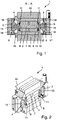
- FIG. 1 shows a diaphragm vacuum pump 1 with two non-positively connected to a piston 2 stationary membranes 3, 4.
- the membranes 3, 4 are each assigned a membrane head 5, 6, against which the membranes 3, 4 drive when the piston 2 is at its maximum deflection.
- coils 7, ie current-carrying conductors, are operated in a magnetic field by permanent magnets 8 with a constantly changing current direction. There is an air gap between the coils 7 and the permanent magnets 8 . This should be as low as possible in order to increase the efficiency of the actuator, consisting of piston 2 and membranes 3, 4.
- the piston 2 is non-magnetic and is mounted on slide bearings 9 . Storage without plain bearings is also possible with optimized positive (stabilizing) radial rigidity of the membrane arrangements (perpendicular to the stroke direction) and negative (destabilizing) radial rigidity of the coil arrangement (perpendicular to the stroke direction).
- an incremental Hall sensor 10 in the 1 is shown only schematically, for detecting the path in the area of the piston 2.
- the Hall sensor 10 is also used for current reversal by depending on the position of the piston 2, the current direction is reversed early.
- Springs 11 are provided for energy recovery.
- the springs 11 are arranged on both sides of the piston 2 .
- Capacitors (not shown) can also be provided for energy recovery.
- the membranes 3, 4 are clamped between a housing 12 and the membrane heads 5, 6, so that a conveying chamber 13, 14 is separated from a drive chamber 15 in a gas-tight manner.
- the permanent magnets 8 are designed as runners. This enables very good heat dissipation from the coil 7 through direct contact with the housing 12 .
- the housing 12 has cooling ribs 16 in particular in the area of the coil 7 . Room air, for example, which has a lower temperature than the housing temperature, can flow around these cooling fins, as a result of which the coil 7 can be kept at a constant temperature.
- the coil 7 shown advantageously consists of several pairs of coils which can be energized differently in order to be able to move the permanent magnet rotor.
- FIG 3 shows a side view of the vacuum pump 1 with the cooling fins 16.
- FIG. 4 shows a perspective view of the diaphragm pump 1.
- the cooling fins 16 can also be seen clearly.
- the vacuum pump 1, which is in 1 is shown, has the Hall sensor 10, which is used to detect the position of the piston 2.
- the control device 17 detects the dead center of the piston as a function of the position of the piston 2.
- a calibration run is carried out before the pump is put into operation, ie before a pumping process.
- the piston 2 moves the membrane 3 into the membrane head 5 or against a mechanical end point of the membrane 3 with a reduced force compared to pump operation.
- the control device 17 continuously detects the actual position of the piston 2 and compares it with a target position.
- the control device 17 determines the end point of the movement of the membrane by comparing the actual position with the target position. This end point is used continuously as the maximum stroke during the pumping operation of the diaphragm vacuum pump 1 .
- the dead center of the piston 2 can be adjusted in such a way that the membrane 3 is arranged in contact with the membrane head 5 .
- the dead center can also be set in such a way that the distance between the membrane and the membrane head is less than 0.3 mm.
- the dead center can also be set in such a way that the membrane 3 is pressed against the membrane head 5 with a certain force.
- the dead center is advantageously set in such a way that the membrane 3 bears completely against the membrane head 5 so that the pumping space 13 has no dead volume, so that the pump performance of the pump is optimized.
- the calibration described is also carried out accordingly for the membrane 4 and the membrane head 6.
- the drive space 15 is sealed against atmospheric pressure.
- the drive chamber 15 is advantageously additionally pumped out.
- the membrane vacuum pump 1 according to 1 has an inlet valve and an outlet valve for each delivery chamber 13, 14.
- FIG 5 shows a modified embodiment of a diaphragm vacuum pump 20.
- the diaphragm vacuum pump 20 has a housing 21 in which the piston 22 is mounted linearly.
- the linear drive consisting of coils and magnets, is in figure 5 not shown, but takes place according to the principle of 1 .
- the vacuum pump has three diaphragm heads 22, 23, 24.
- the membrane heads 22, 23, 24 are associated with membranes 25, 26, 27.
- the membrane 27 is moved by the piston 22 directly via a rod 28.
- the movement of the membranes 25, 26 by the piston 22 takes place via a T-piece 29.
- the membrane heads 22, 23 can be connected in parallel or in series.
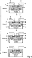
- FIG. 6 shows the functional principle of a membrane vacuum pump according to the prior art for the sake of completeness.
- FIG. 6 shows a membrane vacuum pump 1 with a housing 12 with a membrane 30 which is clamped in the housing 12 at the edge and can be set in a wobbling downward movement by a drive connecting rod 31 of a motor drive.
- a suction chamber 13 which is delimited by the membrane 3 by a housing head 32 and which is delimited in relation to the membrane 3 by the housing head 5 of the housing 12 .
- the housing head 5 there is at least one intake line 18 leading into the pumping chamber 13 with an inlet valve arrangement 33 and at least one discharge line 19 leading out of the suction chamber 13 with an outlet valve arrangement 34.
- the inlet valve arrangement 33 has an inlet valve opening 35 and an inlet valve body 36 closing the inlet valve opening 35 in the event of overpressure in the suction chamber 13 .
- the outlet valve arrangement 34 has a closing outlet valve body 37 when the pressure in the suction chamber 13 is negative.
Landscapes
- Engineering & Computer Science (AREA)
- Mechanical Engineering (AREA)
- General Engineering & Computer Science (AREA)
- Reciprocating Pumps (AREA)
- Control Of Positive-Displacement Pumps (AREA)
Claims (15)
- Procédé d'auto-étalonnage d'une pompe à vide à membrane (1) pour le transport d'un gaz, avec une chambre de refoulement (13, 14) pouvant être remplie avec le gaz, avec un piston (2) pouvant être entraîné linéairement avec un entraînement à bobine oscillante dans une chambre d'entraînement (15), avec une membrane (3, 4), qui sépare la chambre de refoulement (13, 14) et la chambre d'entraînement (15) et qui est disposée de façon oscillante entre la chambre de refoulement (13, 14) et la chambre d'entraînement (15), avec une tête de membrane (5) qui forme avec la membrane (3, 4) la chambre de refoulement (13, 14), dans lequel le piston (2) est constitué par un piston (2) mettant la membrane (3, 4) en mouvement et déplaçable d'une course prédéterminée,
caractérisé en ce qu'il est prévu un dispositif (10) pour détecter un point mort et/ou une position du piston (2), et en ce qu'un dispositif de commande (17) déplace le point mort en fonction du signal détecté du dispositif (10), et en ce qu'avant la mise en service de la pompe (1), c'est-à-dire avant un processus de pompage, un parcours automatique d'étalonnage est effectué, dans lequel le piston (2) déplace la membrane (3) avec une force réduite par rapport au mode pompage dans la tête de membrane (5) ou contre un point final mécanique de la membrane (3). - Procédé selon la revendication 1, caractérisé en ce que le dispositif de commande (17) déplace le point mort sur la base d'un signal d'au moins un détecteur de cognement, et/ou en ce que le dispositif de commande (17) déplace le point mort du piston (2) uniquement pendant un parcours d' étalonnage.
- Procédé selon l'une quelconque des revendications précédentes, caractérisé en ce que le dispositif de commande (17) détecte en continu une position réelle du piston (2) et la compare avec une position de consigne, et en ce que le dispositif de commande (17) détermine à partir de la position réelle et de la position de consigne le point final du déplacement de la membrane (3, 4), en particulier en ce que le point final déterminé de la membrane (3, 4) est enregistré et en ce que l'on utilise le point final comme course maximale pendant en mode pompage.
- Procédé selon l'une quelconque des revendications précédentes, caractérisé en ce que l'on règle le point mort de telle manière qu'il reste entre la membrane (3, 4) et la tête de membrane (5, 6) une distance de moins de 0,5 millimètre, en particulier en ce que l'on règle le point mort de telle manière que la membrane (3, 4) est en contact avec la tête de membrane (5, 6), en particulier en ce que l'on règle le point mort de telle manière que la membrane (3, 4) soit pressée dans la tête de membrane (5, 6).
- Procédé selon l'une quelconque des revendications précédentes, caractérisé en ce que l'on effectue l'étalonnage de manière entièrement automatique, et en ce qu'un parcours d'étalonnage comprend au moins une course du piston (2), en particulier en ce que lors de l'utilisation d'un détecteur de cognement on réduit la course du piston (2) lorsque le dispositif de commande (17) reçoit un signal du détecteur de cognement.
- Procédé selon l'une quelconque des revendications précédentes, caractérisé en ce qu'avant le démarrage du mode pompage de la pompe à vide à membrane (1), on amène la membrane (3, 4) contre la tête de membrane (5, 6), et en ce que le dispositif de commande (17) détecte ce déplacement comme défectueux, et en ce qu'après au moins deux déplacements défectueux le dispositif de commande (17) détecte et diminue la position réelle du point mort du piston (2), et en ce que la diminution de la position réelle du point mort du piston (2) est effectuée avec une valeur prédéfinie, en particulier en ce que la grandeur de la valeur prédéfinie détermine si la membrane (3, 4) au point mort du piston (2) est disposée à une distance de la tête de membrane (5, 6), est en contact avec la tête de membrane (5, 6) ou est pressée contre la tête de membrane (5, 6).
- Pompe à vide à membrane (1) qui est réalisée sous la forme d'une pompe à vide à membrane à auto-étalonnage, pour le transport et le dosage d'un gaz, avec une chambre de refoulement (13, 14) pouvant être remplie avec le gaz, avec un piston (2) pouvant être entraîné linéairement avec un entraînement à bobine oscillante dans une chambre d'entraînement (15), avec une membrane (3, 4) qui sépare la chambre de refoulement (13, 14) et la chambre d'entraînement (15) et qui est disposée de façon oscillante entre la chambre de refoulement (13, 14) et la chambre d'entraînement (15), avec une tête de membrane (5) qui forme avec la membrane (3, 4) la chambre de refoulement (13, 14), dans laquelle le piston (2) est constitué par un piston (2) mettant la membrane (3, 4) en mouvement et déplaçable d'une course prédéterminée,
caractérisée en ce qu'il est prévu un dispositif (10) pour détecter un point mort et/ou une position du piston (2), et en ce qu'il est prévu un dispositif de commande (17) qui est réalisé sous la forme d'un dispositif de commande (17) pouvant déplacer le point mort en fonction du signal détecté du dispositif (10), et en ce que la pompe à vide à membrane, avant la mise en service de la pompe, c'est-à-dire avant un processus de pompage, est réalisée sous la forme d'une pompe à vide à membrane effectuant un parcours automatique d'étalonnage, dans lequel le piston (2) est réalisé sous la forme d'un piston déplaçant la membrane (3) avec une force réduite par rapport au mode pompage dans la tête de membrane (5) ou contre un point final mécanique de la membrane (3). - Pompe à vide à membrane selon la revendication 7, dans laquelle un entraînement à bobine oscillante présente au moins une bobine et au moins un aimant associé à la bobine, caractérisée en ce que la bobine (7) est réalisée comme stator et l'aimant (8) est réalisé comme induit.
- Pompe à vide à membrane selon la revendication 7 pour le transport d'un gaz, avec une chambre de refoulement pouvant être remplie avec le gaz, avec un piston pouvant être entraîné linéairement avec un entraînement à bobine oscillante dans une chambre d'entraînement, avec une membrane, qui sépare la chambre de refoulement et la chambre d'entraînement et qui est disposée de façon oscillante entre la chambre de refoulement et la chambre d'entraînement, avec une tête de membrane, qui forme avec la membrane la chambre de refoulement, le piston étant conçu comme un piston mettant la membrane en mouvement et déplaçable d'une course prédéterminée, dans laquelle l'entraînement à bobine oscillante présente au moins une bobine et au moins un aimant associé à la bobine,
caractérisée en ce que la bobine (7) est réalisée comme stator et l'aimant (8) est réalisé comme induit. - Pompe à vide à membrane selon la revendication 7, 8 ou 9, caractérisée en ce que le stator est relié en conduction de température à un boîtier (12) et en ce que des nervures de refroidissement (16) sont disposées sur le boîtier (12).
- Pompe à vide à membrane selon l'une quelconque des revendications 7 à 10, caractérisée en ce qu'il est prévu au moins un détecteur de cognement, et en ce que le dispositif de commande (17) est réalisé comme un dispositif de commande (17) déplaçant le point mort sur la base d'un signal du détecteur de cognement, et/ou en ce que le dispositif de commande (17) est réalisé comme un dispositif de commande (2) déplaçant le point mort du piston (2) uniquement pendant un parcours d'étalonnage, et/ou en ce que le dispositif (10) de détection d'un point mort et/ou d'une position du piston (2) est réalisé comme un détecteur de Hall, et/ou en ce que le dispositif (10) de détection d'un point mort et/ou d'une position du piston (2) est réalisé comme un détecteur de Hall incrémentiel.
- Pompe à vide à membrane selon l'une quelconque des revendications 7 à 11, caractérisée en ce que la pompe à vide à membrane (1, 21) est réalisée sous la forme d'une pompe à vide à membrane (1, 21) à une tête, à deux têtes ou à plusieurs têtes, en particulier en ce que la chambre d'entraînement (15) est réalisée de manière étanche par rapport à la pression atmosphérique.
- Pompe à vide à membrane selon l'une quelconque des revendications 7 à 12, caractérisée en ce que la chambre d'entraînement (15) est réalisée sous la forme d'une chambre d'entraînement (15) vidée.
- Pompe à vide à membrane selon l'une quelconque des revendications 7 à 13, caractérisée en ce qu'il est prévu au moins un ressort (11) dans la tête de membrane (5, 6) ou dans l'entraînement linéaire pour le rappel du piston (2) et de la membrane (3, 4).
- Pompe à vide à membrane selon l'une quelconque des revendications 7 à 14, caractérisée en ce que la pompe à vide à membrane (1, 21) présente au moins une soupape d'admission (18) et au moins une soupape d'échappement (19), et en ce que les soupapes (18, 19) sont réalisées sous la forme de soupapes à languette et/ou de soupapes sphériques et/ou de soupapes à disque.
Applications Claiming Priority (1)
| Application Number | Priority Date | Filing Date | Title |
|---|---|---|---|
| DE102013113351.7A DE102013113351A1 (de) | 2013-12-03 | 2013-12-03 | Verfahren zur Kalibrierung einer Membranvakuumpumpe sowie Membranvakuumpumpe |
Publications (4)
| Publication Number | Publication Date |
|---|---|
| EP2889481A2 EP2889481A2 (fr) | 2015-07-01 |
| EP2889481A3 EP2889481A3 (fr) | 2015-10-14 |
| EP2889481B1 EP2889481B1 (fr) | 2018-04-04 |
| EP2889481B2 true EP2889481B2 (fr) | 2022-10-26 |
Family
ID=51903814
Family Applications (1)
| Application Number | Title | Priority Date | Filing Date |
|---|---|---|---|
| EP14192137.9A Active EP2889481B2 (fr) | 2013-12-03 | 2014-11-06 | Procédé d'étalonnage d'une pompe sous vide à membrane et pompe sous vide à membrane |
Country Status (3)
| Country | Link |
|---|---|
| EP (1) | EP2889481B2 (fr) |
| JP (1) | JP6154797B2 (fr) |
| DE (1) | DE102013113351A1 (fr) |
Families Citing this family (7)
| Publication number | Priority date | Publication date | Assignee | Title |
|---|---|---|---|---|
| US11002270B2 (en) * | 2016-04-18 | 2021-05-11 | Ingersoll-Rand Industrial U.S., Inc. | Cooling methods for electrically operated diaphragm pumps |
| DE102017112975B3 (de) * | 2017-06-13 | 2018-10-25 | KNF Micro AG | Membranpumpe |
| CN110230585A (zh) * | 2019-06-18 | 2019-09-13 | 苏州思维医疗科技有限公司 | 压力真空控制泵 |
| DE102019117731A1 (de) * | 2019-07-01 | 2021-01-07 | Ebm-Papst St. Georgen Gmbh & Co. Kg | Verfahren zur Positionserfassung der Membran einer elektromotorisch angetriebenen Membranpumpe |
| DE102019117729A1 (de) * | 2019-07-01 | 2021-01-07 | Ebm-Papst St. Georgen Gmbh & Co. Kg | Verfahren zur Positionserfassung der Membran einer elektromotorisch angetriebenen Membranpumpe |
| CN113606121B (zh) * | 2021-08-31 | 2023-09-15 | 广东佛燃天高流体机械设备有限公司 | 一种隔膜式压缩机 |
| CN119804129B (zh) * | 2025-03-11 | 2025-07-08 | 陕西奥德华机械制造有限公司 | 一种计量泵检测校验装置 |
Citations (2)
| Publication number | Priority date | Publication date | Assignee | Title |
|---|---|---|---|---|
| EP1757809A1 (fr) † | 2005-08-22 | 2007-02-28 | ProMinent Dosiertechnik GmbH | Pompe doseuse électromagnétique avec réglage du mouvement et de la vitesse |
| WO2007058579A1 (fr) † | 2005-11-15 | 2007-05-24 | Johan Stenberg | Système de commande pour pompes électromagnétiques |
Family Cites Families (16)
| Publication number | Priority date | Publication date | Assignee | Title |
|---|---|---|---|---|
| DE859477C (de) | 1951-01-30 | 1952-12-15 | Christian Dr Groeber | Kolbenverdichter fuer Kaeltemaschinen |
| DE1960371A1 (de) | 1969-12-02 | 1971-06-09 | Klein Heinrich Georg | Anhebungsfreies Krankenaufnahmefaltsystem,Steckquerholm,auswechselbare,fuer Decken,Gurte und Verbindung Kopfstuetze,loser Querholmgleiter und Magnethalter |
| JPS534491Y2 (fr) * | 1973-01-30 | 1978-02-04 | ||
| JPS5512222A (en) * | 1978-07-11 | 1980-01-28 | Hitachi Metals Ltd | Diaphragm pump |
| DE3246731A1 (de) | 1982-12-17 | 1984-06-20 | Wabco Westinghouse Steuerungstechnik GmbH & Co, 3000 Hannover | Einrichtung zum erfassen der position des kolbens eines arbeitszylinders |
| JP2590209B2 (ja) * | 1988-06-29 | 1997-03-12 | 株式会社長野計器製作所 | 往復動作動装置 |
| JPH09137781A (ja) | 1995-11-15 | 1997-05-27 | Matsushita Refrig Co Ltd | 振動型圧縮機 |
| DE19910920B4 (de) | 1999-03-12 | 2006-05-11 | Rietschle Thomas Memmingen Gmbh | Schwingankermembranpumpe |
| JP2001090662A (ja) * | 1999-09-24 | 2001-04-03 | Sanyo Electric Co Ltd | リニアコンプレッサ |
| BR9907432B1 (pt) | 1999-12-23 | 2014-04-22 | Brasil Compressores Sa | Método de controle de compressor, sistema de monitoração de posição de um pistão e compressor |
| US7322801B2 (en) * | 2003-08-26 | 2008-01-29 | Thomas Industries Inc. | Compact linear air pump and valve package |
| JP4120512B2 (ja) * | 2003-08-27 | 2008-07-16 | 日産自動車株式会社 | 内燃機関の可変圧縮比機構及びそのピストン位置較正方法 |
| DE102004010403A1 (de) | 2004-03-03 | 2005-09-22 | BSH Bosch und Siemens Hausgeräte GmbH | Reversierender Linearantrieb mit Mitteln zur Erfassung einer Ankerposition |
| EP2061971A2 (fr) * | 2006-09-16 | 2009-05-27 | THOMAS MAGNETE GmbH | Pompe à membrane |
| DE102006044248B3 (de) | 2006-09-16 | 2008-04-03 | Thomas Magnete Gmbh | Membranpumpe |
| DE102008029370A1 (de) | 2008-06-20 | 2009-12-24 | BSH Bosch und Siemens Hausgeräte GmbH | Linearverdichter |
-
2013
- 2013-12-03 DE DE102013113351.7A patent/DE102013113351A1/de active Pending
-
2014
- 2014-11-06 EP EP14192137.9A patent/EP2889481B2/fr active Active
- 2014-12-01 JP JP2014243343A patent/JP6154797B2/ja active Active
Patent Citations (2)
| Publication number | Priority date | Publication date | Assignee | Title |
|---|---|---|---|---|
| EP1757809A1 (fr) † | 2005-08-22 | 2007-02-28 | ProMinent Dosiertechnik GmbH | Pompe doseuse électromagnétique avec réglage du mouvement et de la vitesse |
| WO2007058579A1 (fr) † | 2005-11-15 | 2007-05-24 | Johan Stenberg | Système de commande pour pompes électromagnétiques |
Also Published As
| Publication number | Publication date |
|---|---|
| DE102013113351A1 (de) | 2015-06-03 |
| EP2889481B1 (fr) | 2018-04-04 |
| EP2889481A2 (fr) | 2015-07-01 |
| JP6154797B2 (ja) | 2017-06-28 |
| EP2889481A3 (fr) | 2015-10-14 |
| DE102013113351A8 (de) | 2024-05-08 |
| JP2015117696A (ja) | 2015-06-25 |
Similar Documents
| Publication | Publication Date | Title |
|---|---|---|
| EP2889481B2 (fr) | Procédé d'étalonnage d'une pompe sous vide à membrane et pompe sous vide à membrane | |
| DE69830935T2 (de) | Linearverdichter | |
| EP2193058B1 (fr) | Groupe moteur-pompe | |
| US10890166B2 (en) | Non-pulsation pump having stroke adjustment mechanism | |
| EP3508727B1 (fr) | Pompe à spirales et procédé de fonctionnement d'une pompe à spirales | |
| DE10392934B4 (de) | Membranpumpe | |
| WO2015000456A1 (fr) | Pompe à réfrigérant réglable | |
| EP2912310A1 (fr) | Pompe à membrane à piston | |
| DE102014218525B4 (de) | Elektrisches Regelventil für einen Klimakompressor mit einem Sensor zur Bestimmung der Stellung des Regelkolbens | |
| EP2725226A1 (fr) | Pompe à pistons | |
| EP3851674A1 (fr) | Pompe à double diaphragme | |
| DE1453610B2 (de) | Gegentakt-dosierpumpe zum dosieren von fluessigen oder gasfoermigen medien | |
| EP3488107B1 (fr) | Pompe volumétrique oscillante comprenant un entraînement électro-dynamique et son procédé de fonctionnement | |
| EP2354546B1 (fr) | Pompe sous vide à membrane | |
| EP3438455B1 (fr) | Pompe à membrane et procédé d'actionnement sans contact des membranes d'une pluralité de chambres de travail d'une pompe à membrane | |
| DE10309541A1 (de) | Kolbenverdichter | |
| EP3119596B1 (fr) | Dispositif permettant d'étanchéifier et de gonfler des gonflables | |
| EP2918835B1 (fr) | Pompe à membrane | |
| DE102016119930A1 (de) | Verdrängerpumpe mit einstellbarer Anschlagsfläche | |
| CN210977788U (zh) | 一种往复联动双凸轮柱塞泵 | |
| WO2021078781A1 (fr) | Compresseur à piston et son procédé de fonctionnement | |
| DE102014223208B3 (de) | Membranpumpe zur Erzeugung einer nahezu laminaren Strömung sowie Verfahren zum Betrieb einer solchen Membranpumpe | |
| CN113767221B (zh) | 用于往复式机器的完全致动的阀和包括该阀的往复式机器 | |
| DE102009009025A1 (de) | Rotierende Verdrängermaschine | |
| WO2025124852A1 (fr) | Compresseur linéaire |
Legal Events
| Date | Code | Title | Description |
|---|---|---|---|
| PUAI | Public reference made under article 153(3) epc to a published international application that has entered the european phase |
Free format text: ORIGINAL CODE: 0009012 |
|
| 17P | Request for examination filed |
Effective date: 20141106 |
|
| AK | Designated contracting states |
Kind code of ref document: A2 Designated state(s): AL AT BE BG CH CY CZ DE DK EE ES FI FR GB GR HR HU IE IS IT LI LT LU LV MC MK MT NL NO PL PT RO RS SE SI SK SM TR |
|
| AX | Request for extension of the european patent |
Extension state: BA ME |
|
| PUAL | Search report despatched |
Free format text: ORIGINAL CODE: 0009013 |
|
| AK | Designated contracting states |
Kind code of ref document: A3 Designated state(s): AL AT BE BG CH CY CZ DE DK EE ES FI FR GB GR HR HU IE IS IT LI LT LU LV MC MK MT NL NO PL PT RO RS SE SI SK SM TR |
|
| AX | Request for extension of the european patent |
Extension state: BA ME |
|
| RIC1 | Information provided on ipc code assigned before grant |
Ipc: F04B 37/16 20060101ALI20150908BHEP Ipc: F04B 37/14 20060101ALI20150908BHEP Ipc: F04B 43/04 20060101ALI20150908BHEP Ipc: F04B 45/047 20060101ALI20150908BHEP Ipc: F04B 35/04 20060101AFI20150908BHEP Ipc: F04B 51/00 20060101ALI20150908BHEP |
|
| R17P | Request for examination filed (corrected) |
Effective date: 20160321 |
|
| RBV | Designated contracting states (corrected) |
Designated state(s): AL AT BE BG CH CY CZ DE DK EE ES FI FR GB GR HR HU IE IS IT LI LT LU LV MC MK MT NL NO PL PT RO RS SE SI SK SM TR |
|
| GRAP | Despatch of communication of intention to grant a patent |
Free format text: ORIGINAL CODE: EPIDOSNIGR1 |
|
| STAA | Information on the status of an ep patent application or granted ep patent |
Free format text: STATUS: GRANT OF PATENT IS INTENDED |
|
| RIC1 | Information provided on ipc code assigned before grant |
Ipc: F04B 51/00 20060101ALI20171010BHEP Ipc: F04B 43/04 20060101ALI20171010BHEP Ipc: F04B 45/047 20060101ALI20171010BHEP Ipc: F04B 37/14 20060101ALI20171010BHEP Ipc: F04B 37/16 20060101ALI20171010BHEP Ipc: F04B 35/04 20060101AFI20171010BHEP |
|
| INTG | Intention to grant announced |
Effective date: 20171030 |
|
| GRAS | Grant fee paid |
Free format text: ORIGINAL CODE: EPIDOSNIGR3 |
|
| GRAA | (expected) grant |
Free format text: ORIGINAL CODE: 0009210 |
|
| STAA | Information on the status of an ep patent application or granted ep patent |
Free format text: STATUS: THE PATENT HAS BEEN GRANTED |
|
| AK | Designated contracting states |
Kind code of ref document: B1 Designated state(s): AL AT BE BG CH CY CZ DE DK EE ES FI FR GB GR HR HU IE IS IT LI LT LU LV MC MK MT NL NO PL PT RO RS SE SI SK SM TR |
|
| REG | Reference to a national code |
Ref country code: GB Ref legal event code: FG4D Free format text: NOT ENGLISH |
|
| REG | Reference to a national code |
Ref country code: CH Ref legal event code: EP |
|
| REG | Reference to a national code |
Ref country code: AT Ref legal event code: REF Ref document number: 985891 Country of ref document: AT Kind code of ref document: T Effective date: 20180415 |
|
| REG | Reference to a national code |
Ref country code: DE Ref legal event code: R096 Ref document number: 502014007826 Country of ref document: DE |
|
| REG | Reference to a national code |
Ref country code: IE Ref legal event code: FG4D Free format text: LANGUAGE OF EP DOCUMENT: GERMAN |
|
| REG | Reference to a national code |
Ref country code: NL Ref legal event code: MP Effective date: 20180404 |
|
| REG | Reference to a national code |
Ref country code: LT Ref legal event code: MG4D |
|
| PG25 | Lapsed in a contracting state [announced via postgrant information from national office to epo] |
Ref country code: NL Free format text: LAPSE BECAUSE OF FAILURE TO SUBMIT A TRANSLATION OF THE DESCRIPTION OR TO PAY THE FEE WITHIN THE PRESCRIBED TIME-LIMIT Effective date: 20180404 |
|
| PG25 | Lapsed in a contracting state [announced via postgrant information from national office to epo] |
Ref country code: NO Free format text: LAPSE BECAUSE OF FAILURE TO SUBMIT A TRANSLATION OF THE DESCRIPTION OR TO PAY THE FEE WITHIN THE PRESCRIBED TIME-LIMIT Effective date: 20180704 Ref country code: PL Free format text: LAPSE BECAUSE OF FAILURE TO SUBMIT A TRANSLATION OF THE DESCRIPTION OR TO PAY THE FEE WITHIN THE PRESCRIBED TIME-LIMIT Effective date: 20180404 Ref country code: LT Free format text: LAPSE BECAUSE OF FAILURE TO SUBMIT A TRANSLATION OF THE DESCRIPTION OR TO PAY THE FEE WITHIN THE PRESCRIBED TIME-LIMIT Effective date: 20180404 Ref country code: ES Free format text: LAPSE BECAUSE OF FAILURE TO SUBMIT A TRANSLATION OF THE DESCRIPTION OR TO PAY THE FEE WITHIN THE PRESCRIBED TIME-LIMIT Effective date: 20180404 Ref country code: AL Free format text: LAPSE BECAUSE OF FAILURE TO SUBMIT A TRANSLATION OF THE DESCRIPTION OR TO PAY THE FEE WITHIN THE PRESCRIBED TIME-LIMIT Effective date: 20180404 Ref country code: SE Free format text: LAPSE BECAUSE OF FAILURE TO SUBMIT A TRANSLATION OF THE DESCRIPTION OR TO PAY THE FEE WITHIN THE PRESCRIBED TIME-LIMIT Effective date: 20180404 Ref country code: BG Free format text: LAPSE BECAUSE OF FAILURE TO SUBMIT A TRANSLATION OF THE DESCRIPTION OR TO PAY THE FEE WITHIN THE PRESCRIBED TIME-LIMIT Effective date: 20180704 Ref country code: FI Free format text: LAPSE BECAUSE OF FAILURE TO SUBMIT A TRANSLATION OF THE DESCRIPTION OR TO PAY THE FEE WITHIN THE PRESCRIBED TIME-LIMIT Effective date: 20180404 |
|
| PG25 | Lapsed in a contracting state [announced via postgrant information from national office to epo] |
Ref country code: LV Free format text: LAPSE BECAUSE OF FAILURE TO SUBMIT A TRANSLATION OF THE DESCRIPTION OR TO PAY THE FEE WITHIN THE PRESCRIBED TIME-LIMIT Effective date: 20180404 Ref country code: RS Free format text: LAPSE BECAUSE OF FAILURE TO SUBMIT A TRANSLATION OF THE DESCRIPTION OR TO PAY THE FEE WITHIN THE PRESCRIBED TIME-LIMIT Effective date: 20180404 Ref country code: GR Free format text: LAPSE BECAUSE OF FAILURE TO SUBMIT A TRANSLATION OF THE DESCRIPTION OR TO PAY THE FEE WITHIN THE PRESCRIBED TIME-LIMIT Effective date: 20180705 Ref country code: HR Free format text: LAPSE BECAUSE OF FAILURE TO SUBMIT A TRANSLATION OF THE DESCRIPTION OR TO PAY THE FEE WITHIN THE PRESCRIBED TIME-LIMIT Effective date: 20180404 |
|
| PG25 | Lapsed in a contracting state [announced via postgrant information from national office to epo] |
Ref country code: PT Free format text: LAPSE BECAUSE OF FAILURE TO SUBMIT A TRANSLATION OF THE DESCRIPTION OR TO PAY THE FEE WITHIN THE PRESCRIBED TIME-LIMIT Effective date: 20180806 |
|
| REG | Reference to a national code |
Ref country code: DE Ref legal event code: R026 Ref document number: 502014007826 Country of ref document: DE |
|
| PLBI | Opposition filed |
Free format text: ORIGINAL CODE: 0009260 |
|
| PLAX | Notice of opposition and request to file observation + time limit sent |
Free format text: ORIGINAL CODE: EPIDOSNOBS2 |
|
| PG25 | Lapsed in a contracting state [announced via postgrant information from national office to epo] |
Ref country code: DK Free format text: LAPSE BECAUSE OF FAILURE TO SUBMIT A TRANSLATION OF THE DESCRIPTION OR TO PAY THE FEE WITHIN THE PRESCRIBED TIME-LIMIT Effective date: 20180404 Ref country code: EE Free format text: LAPSE BECAUSE OF FAILURE TO SUBMIT A TRANSLATION OF THE DESCRIPTION OR TO PAY THE FEE WITHIN THE PRESCRIBED TIME-LIMIT Effective date: 20180404 Ref country code: SK Free format text: LAPSE BECAUSE OF FAILURE TO SUBMIT A TRANSLATION OF THE DESCRIPTION OR TO PAY THE FEE WITHIN THE PRESCRIBED TIME-LIMIT Effective date: 20180404 Ref country code: RO Free format text: LAPSE BECAUSE OF FAILURE TO SUBMIT A TRANSLATION OF THE DESCRIPTION OR TO PAY THE FEE WITHIN THE PRESCRIBED TIME-LIMIT Effective date: 20180404 |
|
| 26 | Opposition filed |
Opponent name: KNF NEUBERGER GMBH Effective date: 20190102 |
|
| PG25 | Lapsed in a contracting state [announced via postgrant information from national office to epo] |
Ref country code: SM Free format text: LAPSE BECAUSE OF FAILURE TO SUBMIT A TRANSLATION OF THE DESCRIPTION OR TO PAY THE FEE WITHIN THE PRESCRIBED TIME-LIMIT Effective date: 20180404 |
|
| PLBB | Reply of patent proprietor to notice(s) of opposition received |
Free format text: ORIGINAL CODE: EPIDOSNOBS3 |
|
| PG25 | Lapsed in a contracting state [announced via postgrant information from national office to epo] |
Ref country code: SI Free format text: LAPSE BECAUSE OF FAILURE TO SUBMIT A TRANSLATION OF THE DESCRIPTION OR TO PAY THE FEE WITHIN THE PRESCRIBED TIME-LIMIT Effective date: 20180404 |
|
| REG | Reference to a national code |
Ref country code: CH Ref legal event code: PL |
|
| PG25 | Lapsed in a contracting state [announced via postgrant information from national office to epo] |
Ref country code: MC Free format text: LAPSE BECAUSE OF FAILURE TO SUBMIT A TRANSLATION OF THE DESCRIPTION OR TO PAY THE FEE WITHIN THE PRESCRIBED TIME-LIMIT Effective date: 20180404 Ref country code: LU Free format text: LAPSE BECAUSE OF NON-PAYMENT OF DUE FEES Effective date: 20181106 |
|
| REG | Reference to a national code |
Ref country code: BE Ref legal event code: MM Effective date: 20181130 |
|
| REG | Reference to a national code |
Ref country code: IE Ref legal event code: MM4A |
|
| PG25 | Lapsed in a contracting state [announced via postgrant information from national office to epo] |
Ref country code: CH Free format text: LAPSE BECAUSE OF NON-PAYMENT OF DUE FEES Effective date: 20181130 Ref country code: LI Free format text: LAPSE BECAUSE OF NON-PAYMENT OF DUE FEES Effective date: 20181130 |
|
| PG25 | Lapsed in a contracting state [announced via postgrant information from national office to epo] |
Ref country code: IE Free format text: LAPSE BECAUSE OF NON-PAYMENT OF DUE FEES Effective date: 20181106 |
|
| PG25 | Lapsed in a contracting state [announced via postgrant information from national office to epo] |
Ref country code: BE Free format text: LAPSE BECAUSE OF NON-PAYMENT OF DUE FEES Effective date: 20181130 |
|
| PG25 | Lapsed in a contracting state [announced via postgrant information from national office to epo] |
Ref country code: MT Free format text: LAPSE BECAUSE OF FAILURE TO SUBMIT A TRANSLATION OF THE DESCRIPTION OR TO PAY THE FEE WITHIN THE PRESCRIBED TIME-LIMIT Effective date: 20180404 |
|
| PG25 | Lapsed in a contracting state [announced via postgrant information from national office to epo] |
Ref country code: TR Free format text: LAPSE BECAUSE OF FAILURE TO SUBMIT A TRANSLATION OF THE DESCRIPTION OR TO PAY THE FEE WITHIN THE PRESCRIBED TIME-LIMIT Effective date: 20180404 |
|
| PG25 | Lapsed in a contracting state [announced via postgrant information from national office to epo] |
Ref country code: MK Free format text: LAPSE BECAUSE OF NON-PAYMENT OF DUE FEES Effective date: 20180404 Ref country code: HU Free format text: LAPSE BECAUSE OF FAILURE TO SUBMIT A TRANSLATION OF THE DESCRIPTION OR TO PAY THE FEE WITHIN THE PRESCRIBED TIME-LIMIT; INVALID AB INITIO Effective date: 20141106 Ref country code: CY Free format text: LAPSE BECAUSE OF FAILURE TO SUBMIT A TRANSLATION OF THE DESCRIPTION OR TO PAY THE FEE WITHIN THE PRESCRIBED TIME-LIMIT Effective date: 20180404 |
|
| PG25 | Lapsed in a contracting state [announced via postgrant information from national office to epo] |
Ref country code: IS Free format text: LAPSE BECAUSE OF FAILURE TO SUBMIT A TRANSLATION OF THE DESCRIPTION OR TO PAY THE FEE WITHIN THE PRESCRIBED TIME-LIMIT Effective date: 20180804 |
|
| REG | Reference to a national code |
Ref country code: AT Ref legal event code: MM01 Ref document number: 985891 Country of ref document: AT Kind code of ref document: T Effective date: 20191106 |
|
| PG25 | Lapsed in a contracting state [announced via postgrant information from national office to epo] |
Ref country code: AT Free format text: LAPSE BECAUSE OF NON-PAYMENT OF DUE FEES Effective date: 20191106 |
|
| PUAH | Patent maintained in amended form |
Free format text: ORIGINAL CODE: 0009272 |
|
| STAA | Information on the status of an ep patent application or granted ep patent |
Free format text: STATUS: PATENT MAINTAINED AS AMENDED |
|
| 27A | Patent maintained in amended form |
Effective date: 20221026 |
|
| AK | Designated contracting states |
Kind code of ref document: B2 Designated state(s): AL AT BE BG CH CY CZ DE DK EE ES FI FR GB GR HR HU IE IS IT LI LT LU LV MC MK MT NL NO PL PT RO RS SE SI SK SM TR |
|
| REG | Reference to a national code |
Ref country code: DE Ref legal event code: R102 Ref document number: 502014007826 Country of ref document: DE |
|
| PGFP | Annual fee paid to national office [announced via postgrant information from national office to epo] |
Ref country code: IT Payment date: 20250929 Year of fee payment: 12 |
|
| PGFP | Annual fee paid to national office [announced via postgrant information from national office to epo] |
Ref country code: CZ Payment date: 20250903 Year of fee payment: 12 |
|
| PGFP | Annual fee paid to national office [announced via postgrant information from national office to epo] |
Ref country code: DE Payment date: 20250910 Year of fee payment: 12 |
|
| PGFP | Annual fee paid to national office [announced via postgrant information from national office to epo] |
Ref country code: GB Payment date: 20251106 Year of fee payment: 12 |
|
| PGFP | Annual fee paid to national office [announced via postgrant information from national office to epo] |
Ref country code: FR Payment date: 20251128 Year of fee payment: 12 |