EP2888519B2 - Verfahren zum positionieren eines licht formenden körpers - Google Patents
Verfahren zum positionieren eines licht formenden körpers Download PDFInfo
- Publication number
- EP2888519B2 EP2888519B2 EP13753514.2A EP13753514A EP2888519B2 EP 2888519 B2 EP2888519 B2 EP 2888519B2 EP 13753514 A EP13753514 A EP 13753514A EP 2888519 B2 EP2888519 B2 EP 2888519B2
- Authority
- EP
- European Patent Office
- Prior art keywords
- light source
- light
- mounting plate
- reflector
- reference positions
- Prior art date
- Legal status (The legal status is an assumption and is not a legal conclusion. Google has not performed a legal analysis and makes no representation as to the accuracy of the status listed.)
- Active
Links
Images


Classifications
-
- F—MECHANICAL ENGINEERING; LIGHTING; HEATING; WEAPONS; BLASTING
- F21—LIGHTING
- F21S—NON-PORTABLE LIGHTING DEVICES; SYSTEMS THEREOF; VEHICLE LIGHTING DEVICES SPECIALLY ADAPTED FOR VEHICLE EXTERIORS
- F21S41/00—Illuminating devices specially adapted for vehicle exteriors, e.g. headlamps
- F21S41/10—Illuminating devices specially adapted for vehicle exteriors, e.g. headlamps characterised by the light source
- F21S41/19—Attachment of light sources or lamp holders
-
- F—MECHANICAL ENGINEERING; LIGHTING; HEATING; WEAPONS; BLASTING
- F21—LIGHTING
- F21S—NON-PORTABLE LIGHTING DEVICES; SYSTEMS THEREOF; VEHICLE LIGHTING DEVICES SPECIALLY ADAPTED FOR VEHICLE EXTERIORS
- F21S41/00—Illuminating devices specially adapted for vehicle exteriors, e.g. headlamps
- F21S41/10—Illuminating devices specially adapted for vehicle exteriors, e.g. headlamps characterised by the light source
- F21S41/14—Illuminating devices specially adapted for vehicle exteriors, e.g. headlamps characterised by the light source characterised by the type of light source
- F21S41/141—Light emitting diodes [LED]
- F21S41/147—Light emitting diodes [LED] the main emission direction of the LED being angled to the optical axis of the illuminating device
-
- F—MECHANICAL ENGINEERING; LIGHTING; HEATING; WEAPONS; BLASTING
- F21—LIGHTING
- F21S—NON-PORTABLE LIGHTING DEVICES; SYSTEMS THEREOF; VEHICLE LIGHTING DEVICES SPECIALLY ADAPTED FOR VEHICLE EXTERIORS
- F21S41/00—Illuminating devices specially adapted for vehicle exteriors, e.g. headlamps
- F21S41/10—Illuminating devices specially adapted for vehicle exteriors, e.g. headlamps characterised by the light source
- F21S41/19—Attachment of light sources or lamp holders
- F21S41/192—Details of lamp holders, terminals or connectors
-
- F—MECHANICAL ENGINEERING; LIGHTING; HEATING; WEAPONS; BLASTING
- F21—LIGHTING
- F21S—NON-PORTABLE LIGHTING DEVICES; SYSTEMS THEREOF; VEHICLE LIGHTING DEVICES SPECIALLY ADAPTED FOR VEHICLE EXTERIORS
- F21S41/00—Illuminating devices specially adapted for vehicle exteriors, e.g. headlamps
- F21S41/30—Illuminating devices specially adapted for vehicle exteriors, e.g. headlamps characterised by reflectors
- F21S41/39—Attachment thereof
-
- F—MECHANICAL ENGINEERING; LIGHTING; HEATING; WEAPONS; BLASTING
- F21—LIGHTING
- F21S—NON-PORTABLE LIGHTING DEVICES; SYSTEMS THEREOF; VEHICLE LIGHTING DEVICES SPECIALLY ADAPTED FOR VEHICLE EXTERIORS
- F21S43/00—Signalling devices specially adapted for vehicle exteriors, e.g. brake lamps, direction indicator lights or reversing lights
-
- F—MECHANICAL ENGINEERING; LIGHTING; HEATING; WEAPONS; BLASTING
- F21—LIGHTING
- F21V—FUNCTIONAL FEATURES OR DETAILS OF LIGHTING DEVICES OR SYSTEMS THEREOF; STRUCTURAL COMBINATIONS OF LIGHTING DEVICES WITH OTHER ARTICLES, NOT OTHERWISE PROVIDED FOR
- F21V17/00—Fastening of component parts of lighting devices, e.g. shades, globes, refractors, reflectors, filters, screens, grids or protective cages
- F21V17/005—Fastening of component parts of lighting devices, e.g. shades, globes, refractors, reflectors, filters, screens, grids or protective cages with keying means, i.e. for enabling the assembling of component parts in distinctive positions, e.g. for preventing wrong mounting
-
- G—PHYSICS
- G01—MEASURING; TESTING
- G01B—MEASURING LENGTH, THICKNESS OR SIMILAR LINEAR DIMENSIONS; MEASURING ANGLES; MEASURING AREAS; MEASURING IRREGULARITIES OF SURFACES OR CONTOURS
- G01B11/00—Measuring arrangements characterised by the use of optical techniques
- G01B11/26—Measuring arrangements characterised by the use of optical techniques for measuring angles or tapers; for testing the alignment of axes
- G01B11/27—Measuring arrangements characterised by the use of optical techniques for measuring angles or tapers; for testing the alignment of axes for testing the alignment of axes
-
- H—ELECTRICITY
- H05—ELECTRIC TECHNIQUES NOT OTHERWISE PROVIDED FOR
- H05K—PRINTED CIRCUITS; CASINGS OR CONSTRUCTIONAL DETAILS OF ELECTRIC APPARATUS; MANUFACTURE OF ASSEMBLAGES OF ELECTRICAL COMPONENTS
- H05K3/00—Apparatus or processes for manufacturing printed circuits
- H05K3/30—Assembling printed circuits with electric components, e.g. with resistor
- H05K3/32—Assembling printed circuits with electric components, e.g. with resistor electrically connecting electric components or wires to printed circuits
- H05K3/34—Assembling printed circuits with electric components, e.g. with resistor electrically connecting electric components or wires to printed circuits by soldering
-
- F—MECHANICAL ENGINEERING; LIGHTING; HEATING; WEAPONS; BLASTING
- F21—LIGHTING
- F21S—NON-PORTABLE LIGHTING DEVICES; SYSTEMS THEREOF; VEHICLE LIGHTING DEVICES SPECIALLY ADAPTED FOR VEHICLE EXTERIORS
- F21S45/00—Arrangements within vehicle lighting devices specially adapted for vehicle exteriors, for purposes other than emission or distribution of light
- F21S45/40—Cooling of lighting devices
- F21S45/47—Passive cooling, e.g. using fins, thermal conductive elements or openings
-
- F—MECHANICAL ENGINEERING; LIGHTING; HEATING; WEAPONS; BLASTING
- F21—LIGHTING
- F21W—INDEXING SCHEME ASSOCIATED WITH SUBCLASSES F21K, F21L, F21S and F21V, RELATING TO USES OR APPLICATIONS OF LIGHTING DEVICES OR SYSTEMS
- F21W2102/00—Exterior vehicle lighting devices for illuminating purposes
-
- F—MECHANICAL ENGINEERING; LIGHTING; HEATING; WEAPONS; BLASTING
- F21—LIGHTING
- F21W—INDEXING SCHEME ASSOCIATED WITH SUBCLASSES F21K, F21L, F21S and F21V, RELATING TO USES OR APPLICATIONS OF LIGHTING DEVICES OR SYSTEMS
- F21W2102/00—Exterior vehicle lighting devices for illuminating purposes
- F21W2102/20—Illuminance distribution within the emitted light
-
- F—MECHANICAL ENGINEERING; LIGHTING; HEATING; WEAPONS; BLASTING
- F21—LIGHTING
- F21Y—INDEXING SCHEME ASSOCIATED WITH SUBCLASSES F21K, F21L, F21S and F21V, RELATING TO THE FORM OR THE KIND OF THE LIGHT SOURCES OR OF THE COLOUR OF THE LIGHT EMITTED
- F21Y2115/00—Light-generating elements of semiconductor light sources
- F21Y2115/10—Light-emitting diodes [LED]
-
- Y—GENERAL TAGGING OF NEW TECHNOLOGICAL DEVELOPMENTS; GENERAL TAGGING OF CROSS-SECTIONAL TECHNOLOGIES SPANNING OVER SEVERAL SECTIONS OF THE IPC; TECHNICAL SUBJECTS COVERED BY FORMER USPC CROSS-REFERENCE ART COLLECTIONS [XRACs] AND DIGESTS
- Y10—TECHNICAL SUBJECTS COVERED BY FORMER USPC
- Y10T—TECHNICAL SUBJECTS COVERED BY FORMER US CLASSIFICATION
- Y10T29/00—Metal working
- Y10T29/49—Method of mechanical manufacture
- Y10T29/49002—Electrical device making
- Y10T29/49117—Conductor or circuit manufacturing
- Y10T29/49124—On flat or curved insulated base, e.g., printed circuit, etc.
- Y10T29/4913—Assembling to base an electrical component, e.g., capacitor, etc.
- Y10T29/49133—Assembling to base an electrical component, e.g., capacitor, etc. with component orienting
-
- Y—GENERAL TAGGING OF NEW TECHNOLOGICAL DEVELOPMENTS; GENERAL TAGGING OF CROSS-SECTIONAL TECHNOLOGIES SPANNING OVER SEVERAL SECTIONS OF THE IPC; TECHNICAL SUBJECTS COVERED BY FORMER USPC CROSS-REFERENCE ART COLLECTIONS [XRACs] AND DIGESTS
- Y10—TECHNICAL SUBJECTS COVERED BY FORMER USPC
- Y10T—TECHNICAL SUBJECTS COVERED BY FORMER US CLASSIFICATION
- Y10T29/00—Metal working
- Y10T29/49—Method of mechanical manufacture
- Y10T29/49764—Method of mechanical manufacture with testing or indicating
- Y10T29/49778—Method of mechanical manufacture with testing or indicating with aligning, guiding, or instruction
- Y10T29/4978—Assisting assembly or disassembly
Definitions
- the invention relates to a method for positioning a light-shaping body, e.g. a reflector, relative to at least one light source.
- a light-shaping body e.g. a reflector
- a light module for a vehicle headlight or a vehicle headlight has one or more light sources and one or more light-shaping bodies, for example one or more reflectors. Light emerging from the light source is radiated by such a reflector as a desired light pattern in an area in front of the vehicle in which the vehicle headlight is installed.
- the exact positioning of the light source in relation to the reflector is of particular importance.
- LED light sources which for example have one or more light-emitting diodes as light-emitting elements
- the deviations from the target position may only be in the 1/10 mm range, ie the reflector and LED light source(s) must be extremely precise to one another be positioned.
- the pamphlet WO 2005/013315 A2 discloses a vehicle headlamp bulb having a lamp base having locators whose length is adjusted to accurately position the filament.
- the LED light source is first soldered to an LED print (printed circuit board), this print is then attached to a heat sink, e.g. glued to it or screwed to it.
- the reflector is then mounted on the heat sink.
- the tolerance chain can be significantly shortened by the method according to the invention, since tolerances only occur when measuring the position of the light source, tolerances when attaching the reference positions and tolerances of the light-shaping body itself. An exact positioning of the light source(s) and the light-shaping body relative to one another is thereby drastically simplified.
- the at least one light source is an LED light source, which has one or more light-emitting diodes, and that the carrier plate is a printed circuit board for the at least one LED -Light source is.
- step a) the at least one LED light source is soldered to the printed circuit board.
- step b) the geometric center of the at least one Light source is determined and the reference positions are arranged in relation to this geometric center on the support plate.
- the light-shaping body can be positioned even more optimally if the brightest area (or the brightest point) of the at least one light source is determined in step b) and the reference positions are arranged on the carrier plate in relation to this brightest area.
- the position of the at least one light source is determined using an optical measuring method, preferably using a camera. Furthermore, determination by means of laser technology would also be conceivable, which is even more precise but also more expensive.
- the one or more reference positions is/are in the form of one or more holes, for example oblong holes, and/or in the form of one or more reference edges, preferably running in a straight line.
- the appropriate reference surface/edge/hole is created that brings the light-shaping body into a clearly defined position.
- a slot is used, for example, to ensure that the light-shaping body can no longer be twisted, while edges, for example, limit the movement of the light-shaping body in a specific direction, for example in the direction of the light source.
- reference positions are drilled and/or milled.
- the reference positions can be designed in the form of webs, bores, contact surfaces, oblong holes, stops, etc.
- the light-shaping body is fastened by means of at least one, preferably two, fastening elements in relation to the carrier plate.
- the light-shaping body is attached with the at least one attachment element to a heat sink, to which the carrier plate is attached.
- the light-shaping body has a fastening base, which is fastened to the heat sink, so that a particularly stable connection is created.
- the carrier plate itself is attached to the heat sink, for example glued to it, so that good heat transfer from the carrier plate to the heat sink is ensured.
- figure 1 shows an arrangement for carrying out a method according to the invention for positioning a light-shaping body, such as a reflector 1, relative to at least one light source 2.
- a light-shaping body such as a reflector
- figure 1 shows a carrier plate 3, here a printed circuit board (LED print), on which a light source 2 is attached in step a).
- a carrier plate 3 here a printed circuit board (LED print)
- LED print printed circuit board
- the light source 2 is an LED light source, which has two light-emitting diodes here.
- the carrier plate 3 is a printed circuit board for the LED light source 2.
- the LED light source 2 is preferably soldered to the printed circuit board 3 in step a).
- figure 1 also shows a camera 200, by means of which the position of the LED light source 2 on the carrier plate 3 is determined in step b).
- the geometric center of the LED light source 2 is determined in step b), or the relevant brightest area (or the brightest point) of the LED light source 2 is determined in step b).
- the LED light source includes exactly one LED, then the brightest point of this LED is decisive for referencing or positioning the reference positions.
- the LED light source includes two or more LEDs, it depends on the respective application whether the relevant brightest point is that which is generated by all LEDs of the LED light source together, or whether the brightest point is only a specific, defined LED ( eg with 3 LEDs the middle LED) of the LED light source is considered. In the latter case, it is only necessary to measure or determine the brightest point of this one, distinguished LED. It can also be provided that a subset of all LEDs LED light source is considered and their brightest point, which is generated together, is determined.
- the brightest point or area that is decisive for the specific application is determined by measuring one defined LED, several defined LEDs or all LEDs.
- a plurality of reference positions 4 for a reflector 1 are attached to the support plate 3 , the location of the reference positions 4 depending on the position of the LED light source 2 .
- the reference positions are preferably arranged taking into account the geometric center of the LED light source 2 or the brightest area of the LED light source 2.
- the reference positions 4 are in the example shown, as in particular in figure 2 can be seen to a slot open on one side 4a and two rectilinear reference edges or reference planes 4b.
- the reference positions 4 are, for example, drilled, milled or manufactured in some other way, for example laser cutting can also be used.
- FIG. 2 a connector housing 5 for the electrical contacting of the LED light source 2 is also shown.
- the reflector 1 is referenced at these reference positions 4, ie it is aligned and positioned on the carrier plate 3, as is shown in FIGS Figures 3 - 6 shown from different perspectives.
- the reflector 1 has a fastening base 1', which is provided with the corresponding formations corresponding to the reference positions 4a, 4b, for example an extension 1a, which is arranged in the elongated hole 4a, as well as base surfaces or base planes 1b, which come to rest on the reference surfaces 4b of the support plate 3, is equipped.
- a fastening base 1' which is provided with the corresponding formations corresponding to the reference positions 4a, 4b, for example an extension 1a, which is arranged in the elongated hole 4a, as well as base surfaces or base planes 1b, which come to rest on the reference surfaces 4b of the support plate 3, is equipped.
- the at least one reflecting surface of the reflector 1 is not shown in the figures.
- the reflector 1 is positioned on the support plate 3 in the desired position in relation to the LED light source 1 arranged on the support plate 3 and is in a further step e). fixed in relation to the support plate 3.
- the reflector 1 assumes the desired position through the reference positions 4a, 4b, in which it can be held for fastening, for example with its own holding device, not shown, until it is finally fixed in this position (but under certain circumstances releasably), as is illustrated below a concrete embodiment is described as an example.
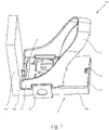
- figure 7 shows a light module 10 according to the invention in this context.
- the restoring element 7 is arranged between the fastening base 1' and a section 6b of the heat sink 6 and can be prestressed, for example by positioning the reflector 1 in its reference position, so that the reflector 1 is at least temporarily in this position holds.
- the at least one restoring element 7 is preferably, as shown, connected in one piece to the reflector 1, in particular to its mounting base 1'.
- the heat sink 6 has two sections 6a, 6a' which are, for example, at right angles to one another.
- the carrier plate 3 is arranged on one of the two sections 6a, for example glued to it.
- the heat sink 6 has a stop area 6b for the restoring element 7, which stop area 6b is formed, for example, in one piece with the two sections 6a, 6a'.
- the restoring element 7 rests against the stop area 6b and is compressed, i.e. the restoring element 7 is prestressed between the section 6b and the mounting base 1', so that the mounting base 1' is pressed into the reference positions 4a, 4b. In this way, the reflector 1 is held in this position at least temporarily.
- the reflector 1 To fasten the reflector, provision is made, for example, for the reflector 1 to be fastened to a heat sink 6 (in the example shown to section 6a of the heat sink 6 to which the carrier plate 3 is fastened) with at least one, preferably with two fastening elements 8 as shown .
- a heat sink 6 in the example shown to section 6a of the heat sink 6 to which the carrier plate 3 is fastened
- at least one, preferably with two fastening elements 8 This is schematic in figure 7 shown.
- the reflector 1 is attached to the heat sink 6 with its attachment base 1', so that a stable attachment is created.
- the support plate 3 itself is attached to the heat sink 6, for example glued to it.
- the reflector 1 or its fastening base 1' preferably has a bearing surface, by means of which the base 1' rests on the circuit board. To this way, the distance between the reflector surface and the at least one light source can be reliably adjusted.
- the fastening elements 8 are designed, for example, as springs, for example as sheet metal springs, which springs are preferably designed in the form of bow springs.
- the springs are preferably clipped onto the heat sink and the mounting base; the base 1' also has, for example, as in FIG figure 7 shown slot-shaped openings for hanging the fasteners 8 on.
- the light module 10 is shown here with a dedicated heat sink 6 assigned only to the light module 10 shown.
- a heat sink is provided for several light modules, so that several carrier plates with a light source and a light-shaping body are arranged on a single heat sink.
- the light-shaping body can also be an optic, such as a lens, a light guide, etc.
Landscapes
- Engineering & Computer Science (AREA)
- General Engineering & Computer Science (AREA)
- Physics & Mathematics (AREA)
- Microelectronics & Electronic Packaging (AREA)
- General Physics & Mathematics (AREA)
- Manufacturing & Machinery (AREA)
- Optics & Photonics (AREA)
- Fastening Of Light Sources Or Lamp Holders (AREA)
- Securing Globes, Refractors, Reflectors Or The Like (AREA)
- Non-Portable Lighting Devices Or Systems Thereof (AREA)
- Led Device Packages (AREA)
- Apparatus Associated With Microorganisms And Enzymes (AREA)
- Length Measuring Devices By Optical Means (AREA)
Description
- Die Erfindung betrifft ein Verfahren zum Positionieren eines Licht formenden Körpers, z.B. eines Reflektors, relativ zu zumindest einer Lichtquelle.
- Zur Erzeugung einer gewünschten Lichtverteilung in dem Bereich vor bzw. hinter einem Fahrzeug weist ein Lichtmodul für einen Fahrzeugscheinwerfer bzw. ein Fahrzeugscheinwerfer ein oder mehrere Lichtquellen sowie einen oder mehrere Licht formende Körper, beispielsweise einen oder mehrere Reflektoren auf. Aus der Lichtquelle austretendes Licht wird von einem solchen Reflektor als gewünschtes Lichtbild in einen Bereich vor dem Fahrzeug, in welches der Fahrzeugscheinwerfer eingebaut ist, abgestrahlt.
- Um ein optimales und insbesondere gesetzeskonformes Lichtbild erzeugen zu können, kommt der exakten Positionierung der Lichtquelle in Bezug auf den Reflektor besondere Bedeutung zu. Beispielsweise dürfen bei der Verwendung von LED-Lichtquellen, welche beispielsweise eine oder mehrere Leuchtdioden als Licht emittierende Elemente aufweisen, die Abweichungen von der Sollposition nur im 1/10 mm-Bereich liegen, d.h. Reflektor und LED-Lichtquelle(n) müssen äußerst exakt zueinander positioniert werden. Die Druckschrift
WO 2005/013315 A2 offenbart eine Glühbirne für Fahrzeugscheinwerfer mit einem Lampensockel, die Positionierelemente aufweist, deren Länge zur genauen Positionierung des Glühfadens angepasst wird. - Bei aktuellen Montagekonzepten wird vorerst die LED-Lichtquelle auf einen LED-Print (Leiterplatte) gelötet, dieser Print wird anschließend an einem Kühlkörper befestigt, z.B. mit diesem verklebt oder an diesem angeschraubt. Der Reflektor wird anschließend auf den Kühlkörper montiert.
- Bei diesem Montagekonzept treten folgende Toleranzen auf: Toleranz in der Position der Leuchtdioden in Bezug auf das LED-Gehäuse, LED-Gehäuse in Bezug auf den LED-Print, LED-Print in Bezug auf Referenzpositionen am Kühlkörper, Kühlkörpertoleranzen an sich, Toleranz Kühlkörper - Reflektor, Reflektortoleranzen.
- Mit einem solchen Montagekonzept ist entsprechend eine optimale Positionierung des Reflektors in Bezug auf die LED-Lichtquellen nicht oder nur sehr aufwändig, in entsprechend aufwändigen Anlagen möglich.
- Es ist eine Aufgabe der Erfindung, ein Verfahren anzugeben, mittels welchem eine exakte und einfache Positionierung eines Reflektors bzw. eines lichtformenden Körper, wie eben eines Reflektors, einer Linse, eines Lichtleiters, einer Blende etc. in Bezug auf eine oder mehrere Lichtquellen möglich wird.
- Diese Aufgabe wird mit einem Verfahren nach Anspruch 1 gelöst, welches folgende Schritte beinhaltet:
- a) Anbringen der zumindest einen Lichtquelle auf einer Trägerplatte;
- b) Vermessen der Position der zumindest einen Lichtquelle auf der Trägerplatte;
- c) Anbringen von einer oder vorzugsweise mehreren Referenzpositionen an der Trägerplatte, wobei die Position der zumindest einen Referenzposition von der Position der zumindest einen Lichtquelle abhängt;
- d) Referenzieren, d.h. Ausrichten des lichtformenden Körpers an der oder den Referenzpositionen an der Trägerplatte; und
- e) Befestigen des lichtformenden Körpers in Bezug auf die Trägerplatte.
- Durch das erfindungsgemäße Verfahren kann die Toleranzkette deutlich verkürzt werden, da nur noch Toleranzen bei der Vermessung des Position der Lichtquelle, Toleranzen beim Anbringen der Referenzpositionen und Toleranzen des Licht formenden Körpers an sich auftreten. Eine exakte Positionierung der Lichtquelle(n) und des Licht formenden Körpers zueinander wird dadurch drastisch vereinfacht.
- Bei einer nicht erfindungsgemässen Ausführungsform sind folgende Schritte vorgesehen:
- a) Anbringen von einer oder vorzugsweise mehreren Referenzpositionen an einer Trägerplatte für zumindest eine Lichtquelle;
- b) Vermessen der Position der zumindest einen Referenzposition auf der Trägerplatte;
- c) Anbringen der zumindest einen Lichtquelle auf der Trägerplatte unter Berücksichtigung der Position der zumindest einen Referenzposition;
- d) Referenzieren, d.h. Ausrichten des lichtformenden Körpers an der oder den Referenzpositionen an der Trägerplatte; und
- e) Befestigen des lichtformenden Körpers an der Trägerplatte bzw. in Bezug auf die Trägerplatte.
- Bei einer konkreten Ausführungsform, bei welcher ein exaktes Positionieren des licht formenden Körpers besonders wichtig ist, ist vorgesehen, dass die zumindest eine Lichtquelle eine LED-Lichtquelle ist, welche eine oder mehrere Leuchtdioden aufweist, und dass die Trägerplatte eine Leiterplatte für die zumindest eine LED-Lichtquelle ist.
- Vorzugsweise ist dabei vorgesehen, dass in Schritt a) die zumindest eine LED-Lichtquelle mit der Leiterplatte verlötet wird.
- Um ein einfaches und exaktes Positionieren zu ermöglichen, ist beispielsweise vorgesehen, dass in Schritt b) die geometrische Mitte der zumindest einen Lichtquelle ermittelt wird und die Referenzpositionen in Bezug auf diese geometrische Mitte auf der Trägerplatte angeordnet werden.
- Noch optimaler kann die Positionierung des licht formenden Körpers erfolgen, wenn in Schritt b) der hellste Bereich (bzw. der hellste Punkt) der zumindest einen Lichtquelle ermittelt wird und die Referenzpositionen in Bezug auf diesen hellsten Bereich auf der Trägerplatte angeordnet werden.
- Bei einer konkreten Ausführungsform deserfindungsgemäßen Verfahrens ist vorgesehen, dass die Position der zumindest einen Lichtquelle mittels einer optischen Meßmethode, vorzugsweise mit einer Kamera ermittelt wird. Weiters wäre auch die Ermittlung mittels Lasertechnikdenkbar, welche noch genauer aber auch teurer ist.
- Grundsätzlich sind auch mechanische Meßmethoden einsetzbar, optische Meßmethoden werden allerdings bevorzugt.
- Weiters ist bei konkreten Ausführungsformen vorgesehen, dass die eine oder die mehreren Referenzpositionen in Form von einer oder mehreren Löchern, beispielsweise Langlöchern, und/oder in Form von einer oder mehreren, vorzugsweise geradlinig verlaufenden Referenzkanten ausgebildet ist/sind.
- Je nach Anwendung und Ausgestaltung des licht formenden Körpers wird die geeignete Referenzfläche/Kante/Loch erstellt, die den licht formenden Körper in eine klar definierte Lage bringt. Ein Langloch dient etwa dazu, dass der licht formende Körper sich nicht mehr verdrehen lässt, während beispielsweise Kanten die Bewegung des licht formenden Körper in eine bestimmte Richtung, etwa in Richtung zu der Lichtquelle hin begrenzen.
- Beispielsweise kann vorgesehen sein, dass Referenzpositionen gebohrt und/oder gefräst werden.
- Die Referenzpositionen können grundsätzlich in Form von Stegen, Bohrungen, Auf- bzw. Anlageflächen, Langlöchern, Anschlägen etc. ausgebildet sein. Erfindungsgemäß ist außerdem vorgesehen, dass der lichtformende Körper mittels zumindest eines, vorzugsweise zweier Befestigungselemente in Bezug auf die Trägerplatte befestigt wird.
- Für eine stabile Befestigung ist erfindungsgemäß vorgesehen, dass der lichtformende Körper mit dem zumindest einen Befestigungselement an einem Kühlkörper, an welchem die Trägerplatte befestigt ist, befestigt wird.
- Dazu weist der lichtformende Körper bei einer konkreten Ausführungsform einen Befestigungssockels auf, dieser wird an dem Kühlkörper befestigt, sodass eine besondere stabile Verbindung entsteht.
- Die Trägerplatte selbst ist an dem Kühlkörper befestigt, beispielsweise mit diesem verklebt, sodass ein guter Wärmeübergang von der Trägerplatte auf den Kühlkörper gewährleistet ist.
- Im Folgenden ist die Erfindung an Hand der Zeichnung näher erörtert. In dieser zeigt
-
Fig. 1 einen prinzipiellen Aufbau zur erfindungsgemäßen Positionierung von Referenzpositionen an einer Trägerplatte, -
Fig. 2 die Trägerplatte ausFigur 1 in einer Detailansicht, -
Fig. 3 eine Reflektor, positioniert an einer Trägerplatte, in einer Seitenansicht, -
Fig. 4 den Reflektor ausFigur 3 , in einer Ansicht von der gegenüberliegenden Seite, -
Fig. 5 eine Ansicht der Trägerplatte von unten mit positioniertem Reflektor, -
Fig. 6 eine Ansicht auf die Trägerplatte mit angesetztem Reflektor von schräg oben, und -
Fig. 7 eine Ansicht eines an einem Kühlkörper in Bezug auf die Trägerplatte befestigten Reflektors. -
Figur 1 zeigt eine Anordnung zum Durchführen eines erfindungsgemäßen Verfahrens zum Positionieren eines Licht formenden Körpers, wie beispielsweise eines Reflektors 1, relativ zu zumindest einer Lichtquelle 2. -
Figur 1 zeigt eine Trägerplatte 3, hier eine Leiterplatte (LED-Print), auf welcher in einem Schritt a) eine Lichtquelle 2 angebracht wird. - Bei der gezeigten Variante ist die Lichtquelle 2 eine LED-Lichtquelle, welche hier zwei Leuchtdioden aufweist. Entsprechend ist, wie oben schon erwähnt, die Trägerplatte 3 eine Leiterplatte für die LED-Lichtquelle 2. Vorzugsweise wird dabei in Schritt a) die LED-Lichtquelle 2 mit der Leiterplatte 3 verlötet.
-
Figur 1 zeigt weiters eine Kamera 200, mittels welcher in Schritt b) die Position der LED-Lichtquelle 2 auf der Trägerplatte 3 ermittelt wird. - Dabei wird in Schritt b) beispielsweise die geometrische Mitte der LED-Lichtquelle 2 ermittelt, oder es wird in Schritt b) der maßgebliche hellste Bereich (bzw. der hellste Punkt) der LED-Lichtquelle 2 ermittelt.
- Umfasst dabei die LED-Lichtquelle genau eine LED, so ist für das Referenzieren bzw. Positionieren der Referenzpositionen der hellste Punkt dieser LED maßgeblich.
- Umfasst die LED-Lichtquelle zwei oder mehrere LEDs, so hängt es vom jeweiligen Anwendungsfall ab, ob der relevante hellste Punkt jener ist, der von allen LEDs der LED-Lichtquelle gemeinsam erzeugtwird, oder ob etwa der hellste Punkt lediglich einer bestimmten, definierten LED (z.B. bei 3 LEDs die mittlere LED) der LED-Lichtquelle betrachtet wird. In letzterem Fall ist nur die Vermessung bzw. Ermittlung des hellsten Punktesdieser einen, ausgezeichneten LED notwendig. Es kann auch vorgesehen sein, dass ein Teilmenge aller LEDs einer LED-Lichtquelle betrachtet und deren gemeinsam erzeugter hellster Punkt ermittelt wird.
- Generell wird also nach der Bestückung der LED-Platine mit der LED-Lichtquelle der für den konkreten Anwendungsfall maßgebliche hellste Punkt bzw. Bereich durch Vermessung der einen definierten, der mehreren definierten LEDs oder alles LEDs ermittelt.
- Es ist auch denkbar, dass fix, etwa von Herstellerseite der Leuchtdioden bzw. der LED-Lichtquellen vorgegeben ist, welcher Punkt der hellste Punkt ist bzw. welcher Punkt als Ausgangspunkt zur Referenzierung verwendet werden soll.
- In einem nächsten Schritt c) werden mehrere Referenzpositionen 4 für einen Reflektor 1 an der Trägerplatte 3 angebracht, wobei die Lage der Referenzpositionen 4 von der Position der LED-Lichtquelle 2 abhängt.
- Das Anordnen der Referenzpositionen erfolgt dabei vorzugsweise unter Berücksichtigung der geometrischen Mitte der LED-Lichtquelle 2 oder des hellsten Bereiches der LED-Lichtquelle 2.
- Bei den Referenzpositionen 4 handelt es sich in dem gezeigten Beispiel, wie insbesondere in
Figur 2 zu erkennen ist, um ein an einer Seite offenes Langloch 4a sowie um zwei geradlinig verlaufende Referenzkanten bzw. Referenzebenen 4b. Die Referenzpositionen 4 werden beispielsweise gebohrt, gefräst oder auf andere Art und Weise gefertigt, z.B. kann auch Laserschneiden zum Einsatz kommen. - Weiters ist in
Figur 2 noch ein Steckergehäuse 5 für die elektrische Kontaktierung der LED-Lichtquelle 2 gezeigt. - An diesen Referenzpositionen 4 wird in einem nächsten Schritt d) der Reflektor 1 referenziert, d.h. an der Trägerplatte 3 ausgerichtet und positioniert, wie dies in den
Figuren 3 - 6 aus verschiedenen Ansichten dargestellt ist. - Der Reflektor 1 verfügt dabei in der gezeigten Ausführungsform über einen Befestigungssockel 1', der mit den entsprechenden, zu den Referenzpositionen 4a, 4b korrespondierenden Ausformungen, beispielsweise einem Fortsatz 1a, welcher in dem Langloch 4a angeordnet wird, sowie von Sockelflächen bzw. Sockelebenen 1b, welche zur Anlage an den Referenzflächen 4b der Trägerplatte 3 gelangen, ausgestattet ist. (Die zumindest eine reflektierende Fläche des Reflektors 1 ist in den Figuren nicht dargestellt.)
- In den
Figuren 3 und 4 ist die Referenzierung des Reflektors bzw. des Reflektorsockels 1' an den Referenzflächen 4b mit seinen Abschnitten 1b gut zu erkennen, während dieFiguren 5 und 6 zeigen, wie der Reflektor 1 bzw. der Sockel 1' mit dem Fortsatz 1a in dem Langloch 4a positioniert ist. - Auf diese Weise ist der Reflektor 1 in der gewünschten Position in Bezug auf die auf der Trägerplatte 3 angeordnete LED-Lichtquelle 1 an der Trägerplatte 3 positioniert und wird in einem weiteren Schritt e). in Bezug auf die Trägerplatte 3 befestigt.
- Durch die Referenzpositionen 4a, 4b nimmt der Reflektor 1 die gewünschte Position ein, in dieser kann erzum Befestigen beispielsweise miteinereigenen, nicht dargestellten Haltevorrichtung gehalten werden, bis er schlussendlich in dieser Position endgültig (unter Umständen aber lösbar) fixiert wird, wie dies unten an Hand einer konkreten Ausführungsform beispielhaft beschrieben ist.
- Es kann aber auch vorgesehen sein, dass z.B. ein oder mehrere Rückstellelemente 7, beispielsweise in Form von einer oder mehreren Feder (etwa Druckfedern) vorgesehen sind, welche den Reflektor bzw. allgemein den licht formenden Körper solange in seiner Referenzposition halten, bis dieser fixiert wird.
-
Figur 7 zeigt in diesem Zusammenhang ein erfindungsgemäßes Lichtmodul 10. Das Rückstellelement 7 ist zwischen dem Befestigungssockel 1' und einem Abschnitt 6b des Kühlkörpers 6 angeordnet und kann beispielsweise durch Positionieren des Reflektors 1 in seiner Referenzposition vorgespannt werden, sodass es den Reflektor 1 in dieser Position zumindest vorübergehend hält. - Das zumindest eine Rückstellelement 7 ist vorzugsweise, wie dargestellt, einstückig mit dem Reflektor 1, insbesondere mit dessen Befestigungssockel 1' verbunden.
- Konkret weist der Kühlkörper 6 zwei Abschnitte 6a, 6a' auf, welche beispielsweise rechtwinkelig zueinander stehen. Die Trägerplatte 3 ist auf einem der beiden Abschnitte 6a angeordnet, beispielsweise mit diesem verklebt. Weiters weist der Kühlkörper 6 einen Anschlagbereich 6b für das Rückstellelement 7 auf, welcher Anschlagbereich 6b beispielsweise einstückig mit den beiden Abschnitten 6a, 6a' ausgebildet ist.
- Bei einem Positionieren des Reflektors 1 liegt das Rückstellelement 7 an dem Anschlagbereich 6b an und wird zusammengedrückt, d.h. das Rückstellelement 7 ist zwischen dem Abschnitt 6b und dem Befestigungssockel 1' vorgespannt, sodass der Befestigungssockel 1' in die Referenzpositionen 4a, 4b gedrückt wird. Auf diese Weise wird der der Reflektor 1 in dieser Position zumindest vorübergehend gehalten.
- Zur Befestigung des Reflektors ist beispielsweise vorgesehen, dass der Reflektor 1 mit zumindest einem, vorzugsweise wie dargestellt mit zwei Befestigungselementen 8 an einem Kühlkörper 6 (in dem gezeigten Beispiel an Abschnitt 6a des Kühlkörpers 6, an welchem die Trägerplatte 3 befestigt ist), befestigt wird. Dies ist schematisch in
Figur 7 gezeigt. - Konkret wird dabei der Reflektor 1 mit seinem Befestigungssockel 1' an dem Kühlkörper 6 befestigt, sodass eine stabile Befestigung entsteht.
- Die Trägerplatte 3 selbst ist an dem Kühlkörper 6 befestigt, beispielsweise mit diesem verklebt.
- Vorzugsweise verfügt der Reflektor 1 bzw. sein Befestigungssockel 1' über eine Auflagefläche, mittels welcher der Sockel 1' auf der Platine aufliegt. Auf diese Weise kann der Abstand der Reflektorfläche zu der zumindest einen Lichtquelle zuverlässig eingestellt werden.
- Die Befestigungselemente 8 sind beispielsweise als Feder, z.B. als Blechfeder ausgebildet, welche Federn vorzugsweise in Form von Bügelfedern ausgebildet sind. Die Federn werden auf den Kühlkörper und den Befestigungssockel bei dieser Ausführungsform vorzugsweise aufgeklipst, der Sockel 1' weistzusätzlich beispielsweise wie in
Figur 7 gezeigt noch schlitzförmige Öffnungen zum Einhängen der Befestigungselemente 8 auf. - Das Lichtmodul 10 ist hier der besseren Übersichtlichkeit halber mit einem dezidierten, nur dem gezeigten Lichtmodul 10 zugeordneten Kühlkörper 6 dargestellt. In der Praxis kann aber auch vorgesehen sein, dass ein Kühlkörper für mehrere Lichtmodule vorgesehen ist, sodass also auf einem einzigen Kühlkörper mehrere Trägerplatten mit Lichtquelle und licht formendem Körper angeordnet sind.
- Die Erfindung wurde obenstehend an Hand eines Reflektors erörtert, bei dem lichtformenden Körper kann es sich aber auch um eine Optik, etwa eine Linse, einen Lichtleiter etc. handeln.
Claims (5)
- Verfahren zum Positionieren eines Licht formenden Körpers, z.B. eines Reflektors (1), relativ zu zumindest einer LED-Lichtquelle (2),mit den folgenden Schritten:a) Anbringen der zumindest einen Lichtquelle (2) auf einer Trägerplatte (3);b) Vermessen der Position der zumindest einen Lichtquelle (2) auf der Trägerplatte (3);c) Anbringen von einer oder vorzugsweise mehreren Referenzpositionen (4) an der Trägerplatte (3), wobei die Position der zumindest einen Referenzposition (4) von der Position der zumindest einen Lichtquelle (2) abhängt;d) Referenzieren, d.h. Ausrichten des lichtformenden Körpers an der oder den Referenzpositionen (4) an der Trägerplatte (3); unde) Befestigen des lichtformenden Körpers in Bezug auf die Trägerplatte (3),wobei die eine oder die mehreren Referenzpositionen (4) in Form von einer oder mehreren Löchern, beispielsweise Langlöchern (4a), und/oder in Form von einer oder mehreren, vorzugsweise geradlinig verlaufenden Referenzkanten (4b) ausgebildet ist/sind,dadurch gekennzeichnet, dassin Schritt b)die geometrische Mitte der zumindest einen Lichtquelle (2) ermittelt wird und die Referenzpositionen (4) in Bezug auf diese geometrische Mitte auf der Trägerplatte (3) angeordnet werden, oderder maßgebliche hellste Bereich bzw. der hellste Punkt der zumindest einen Lichtquelle (2) ermittelt wird und die Referenzpositionen (4) in Bezug auf diesen maßgeblichen hellsten Bereich bzw. diesen hellsten Punkt auf der Trägerplatte (3) angeordnet werden, und wobei der lichtformende Körper in Bezug auf die Trägerplatte (3) befestigt wird, indemer mittels zumindest eines, vorzugsweise zweier Befestigungselemente (8) an einem Kühlkörper (6), an welchem die Trägerplatte (3) befestigt ist, befestigt wird.
- Verfahren nach Anspruch 1, dadurch gekennzeichnet, dass die zumindest eine Lichtquelle (2) eine LED-Lichtquelle ist, welche eine oder mehrere Leuchtdioden aufweist, und dass die Trägerplatte (3) eine Leiterplatte für die zumindest eine LED-Lichtquelle ist.
- Verfahren nach Anspruch 2, dadurch gekennzeichnet, dass in Schritt a) die zumindest eine LED-Lichtquelle (2) mit der Leiterplatte (3) verlötet wird.
- Verfahren nach einem der Ansprüche 1 bis 3, dadurch gekennzeichnet, dass die Position der zumindest einen Lichtquelle (2) bzw. der zumindest einen Referenzposition mittels einer optischen Meßmethode, vorzugsweise mit einer Kamera (200) ermittelt wird.
- Verfahren nach einem der Ansprüche 1 bis 4, dadurch gekennzeichnet, dass Referenzpositionen (4) gebohrt und/oder gefräst werden.
Applications Claiming Priority (2)
| Application Number | Priority Date | Filing Date | Title |
|---|---|---|---|
| ATA50336/2012A AT513362B1 (de) | 2012-08-23 | 2012-08-23 | Verfahren zum Positionieren eines Licht formenden Körpers |
| PCT/AT2013/050138 WO2014028954A1 (de) | 2012-08-23 | 2013-07-22 | Verfahren zum positionieren eines licht formenden körpers |
Publications (3)
| Publication Number | Publication Date |
|---|---|
| EP2888519A1 EP2888519A1 (de) | 2015-07-01 |
| EP2888519B1 EP2888519B1 (de) | 2017-05-31 |
| EP2888519B2 true EP2888519B2 (de) | 2022-04-13 |
Family
ID=49080590
Family Applications (1)
| Application Number | Title | Priority Date | Filing Date |
|---|---|---|---|
| EP13753514.2A Active EP2888519B2 (de) | 2012-08-23 | 2013-07-22 | Verfahren zum positionieren eines licht formenden körpers |
Country Status (8)
| Country | Link |
|---|---|
| US (1) | US9933253B2 (de) |
| EP (1) | EP2888519B2 (de) |
| JP (1) | JP6150147B2 (de) |
| CN (1) | CN104541099B (de) |
| AT (1) | AT513362B1 (de) |
| BR (1) | BR112015003169A2 (de) |
| MX (1) | MX350372B (de) |
| WO (1) | WO2014028954A1 (de) |
Families Citing this family (17)
| Publication number | Priority date | Publication date | Assignee | Title |
|---|---|---|---|---|
| DE102013219087A1 (de) | 2013-09-23 | 2015-03-26 | Osram Opto Semiconductors Gmbh | Verfahren und Vorrichtung zum Bearbeiten eines optoelektronischen Bauteils |
| DE102014101784B4 (de) | 2014-02-13 | 2024-03-14 | HELLA GmbH & Co. KGaA | Verfahren zum Aufbau eines LED- Lichtmoduls |
| DE102014224494A1 (de) * | 2014-12-01 | 2016-06-02 | Automotive Lighting Reutlingen Gmbh | Verfahren zur Herstellung einer Komponente einer Beleuchtungseinrichtung für ein Kraftfahrzeug |
| DE102015207709A1 (de) * | 2015-04-27 | 2016-10-27 | Automotive Lighting Reutlingen Gmbh | Verfahren und Vorrichtung zur Anordnung eines Schaltungsträgers mit einer Halbleiterlichtquelle in einer bestimmten Lage relativ zu einem optischen System einer Beleuchtungseinrichtung |
| DE102016000078B4 (de) | 2016-01-07 | 2023-08-17 | Ic-Haus Gmbh | Verfahren zur Herstellung einer elektronischen Baugruppe, elektronische Baugruppe und Verfahren zur Montage einer elektronischen Baugruppe |
| DE102016201206A1 (de) * | 2016-01-27 | 2017-07-27 | Automotive Lighting Reutlingen Gmbh | Verfahren zur Verarbeitung einer Halteeinrichtung für ein Lichtmodul einer Beleuchtungseinrichtung eines Kraftfahrzeugs |
| DE102016108260A1 (de) * | 2016-05-04 | 2017-11-09 | Automotive Lighting Reutlingen Gmbh | Verfahren zur Anordnung eines Schaltungsträgers und Vorrichtung zur Anordnung eines Schaltungsträgers |
| DE102016119792A1 (de) * | 2016-10-18 | 2018-04-19 | Automotive Lighting Reutlingen Gmbh | Verfahren zur Anordnung eines Schaltungsträgers und Beleuchtungseinrichtung für ein Kraftfahrzeug mit einem nach diesem Verfahren angeordneten Schaltungsträger |
| DE102017122560A1 (de) * | 2017-09-28 | 2019-03-28 | Automotive Lighting Reutlingen Gmbh | LED-Scheinwerfermodul |
| EP3492804A1 (de) * | 2017-12-04 | 2019-06-05 | ZKW Group GmbH | Kraftfahrzeugscheinwerfer und verfahren |
| JP6968015B2 (ja) * | 2018-03-22 | 2021-11-17 | 三菱電機株式会社 | 車載用灯具及び車載用灯具の製造方法 |
| JP7298995B2 (ja) * | 2018-06-05 | 2023-06-27 | 株式会社小糸製作所 | ランプユニットの製造方法 |
| DE102018113561B4 (de) * | 2018-06-07 | 2023-08-10 | Automotive Lighting Reutlingen Gmbh | Verfahren zum Montieren und Justieren eines DMD-Chips in einem Lichtmodul für einen Kraftfahrzeugscheinwerfer |
| DE102019116865A1 (de) * | 2019-06-24 | 2020-12-24 | HELLA GmbH & Co. KGaA | Leuchteinheit für ein Kraftfahrzeug, mit einem Reflektor, einer Leiterplatte und einem Kühlkörper |
| DE102022108281A1 (de) | 2022-04-06 | 2023-10-12 | Marelli Automotive Lighting Reutlingen (Germany) GmbH | Lichtmodul und Kraftfahrzeugbeleuchtungseinrichtung mit einem solchen Lichtmodul |
| DE102022108283A1 (de) | 2022-04-06 | 2023-10-12 | Marelli Automotive Lighting Reutlingen (Germany) GmbH | Lichtmodul, Kraftfahrzeugbeleuchtungseinrichtung mit einem solchen Lichtmodul und Verfahren zur Montage eines optischen Systems eines Lichtmoduls an einem Lichtquellenmodul des Lichtmoduls |
| DE102024203630B3 (de) * | 2024-04-18 | 2025-08-21 | Aumovio Autonomous Mobility Germany Gmbh | Verfahren zur Herstellung einer Sensorbaugruppe |
Citations (1)
| Publication number | Priority date | Publication date | Assignee | Title |
|---|---|---|---|---|
| US20070058904A1 (en) † | 2005-09-14 | 2007-03-15 | Takuma Ban | Method of alignment of an optical module and an optical module using thereof |
Family Cites Families (15)
| Publication number | Priority date | Publication date | Assignee | Title |
|---|---|---|---|---|
| JP2004207655A (ja) * | 2002-12-26 | 2004-07-22 | Matsushita Electric Ind Co Ltd | 金属ベース基板および発光ユニット |
| JP2005044699A (ja) * | 2003-07-24 | 2005-02-17 | Koito Mfg Co Ltd | 車両用灯具及び光源モジュール |
| WO2005013315A2 (en) * | 2003-08-01 | 2005-02-10 | Philips Intellectual Property & Standards Gmbh | Lamp and method of manufacturing same |
| DE10341884B4 (de) * | 2003-09-09 | 2007-10-18 | Intedis Gmbh & Co. Kg | Flexible Schaltungsträgeranordnung |
| JP4343720B2 (ja) * | 2004-01-23 | 2009-10-14 | 株式会社小糸製作所 | 灯具 |
| CN100539214C (zh) * | 2004-10-29 | 2009-09-09 | 奥斯兰姆奥普托半导体有限责任公司 | 照明装置,汽车车头灯以及照明装置的制造方法 |
| DE102007011430A1 (de) * | 2007-03-08 | 2008-09-11 | Osram Gesellschaft mit beschränkter Haftung | Scheinwerfer |
| JP4999551B2 (ja) | 2007-05-24 | 2012-08-15 | 株式会社小糸製作所 | 発光素子モジュール |
| JP4984058B2 (ja) * | 2007-05-25 | 2012-07-25 | スタンレー電気株式会社 | 光源装置及び車両前照灯 |
| DE102009023268A1 (de) * | 2009-05-29 | 2010-06-10 | Osram Gesellschaft mit beschränkter Haftung | LED-Beleuchtungseinheit mit Reflektor |
| DE102010002728A1 (de) * | 2009-10-16 | 2011-04-21 | Osram Gesellschaft mit beschränkter Haftung | Leuchtmodul, Leuchtvorrichtung mit einem Leuchtmodul, Verfahren zum Zusammenbau eines Leuchtmoduls und Verfahren zum Zusammenbau einer Leuchtvorrichtung |
| JP2013535765A (ja) * | 2010-07-14 | 2013-09-12 | コーニンクレッカ フィリップス エヌ ヴェ | 光学要素のための取付要素を有するled照明アセンブリ |
| JP5706701B2 (ja) * | 2011-02-03 | 2015-04-22 | 株式会社小糸製作所 | 車輌用前照灯 |
| JP5628700B2 (ja) * | 2011-02-10 | 2014-11-19 | 株式会社小糸製作所 | 車輌用前照灯 |
| CN202371614U (zh) * | 2011-11-25 | 2012-08-08 | 比亚迪股份有限公司 | 一种车用前照灯 |
-
2012
- 2012-08-23 AT ATA50336/2012A patent/AT513362B1/de active
-
2013
- 2013-07-22 EP EP13753514.2A patent/EP2888519B2/de active Active
- 2013-07-22 WO PCT/AT2013/050138 patent/WO2014028954A1/de not_active Ceased
- 2013-07-22 US US14/419,852 patent/US9933253B2/en active Active
- 2013-07-22 CN CN201380044358.8A patent/CN104541099B/zh active Active
- 2013-07-22 MX MX2015002315A patent/MX350372B/es active IP Right Grant
- 2013-07-22 BR BR112015003169A patent/BR112015003169A2/pt not_active IP Right Cessation
- 2013-07-22 JP JP2015527737A patent/JP6150147B2/ja active Active
Patent Citations (1)
| Publication number | Priority date | Publication date | Assignee | Title |
|---|---|---|---|---|
| US20070058904A1 (en) † | 2005-09-14 | 2007-03-15 | Takuma Ban | Method of alignment of an optical module and an optical module using thereof |
Also Published As
| Publication number | Publication date |
|---|---|
| CN104541099B (zh) | 2017-12-22 |
| JP6150147B2 (ja) | 2017-06-21 |
| MX350372B (es) | 2017-09-04 |
| US9933253B2 (en) | 2018-04-03 |
| JP2015529951A (ja) | 2015-10-08 |
| WO2014028954A1 (de) | 2014-02-27 |
| MX2015002315A (es) | 2015-06-23 |
| EP2888519B1 (de) | 2017-05-31 |
| CN104541099A (zh) | 2015-04-22 |
| US20150211843A1 (en) | 2015-07-30 |
| EP2888519A1 (de) | 2015-07-01 |
| AT513362A1 (de) | 2014-03-15 |
| BR112015003169A2 (pt) | 2017-10-10 |
| AT513362B1 (de) | 2014-06-15 |
Similar Documents
| Publication | Publication Date | Title |
|---|---|---|
| EP2888519B2 (de) | Verfahren zum positionieren eines licht formenden körpers | |
| EP2888520B1 (de) | Lichtmodul für ein kraftfahrzeug | |
| EP3004724B1 (de) | Beleuchtungsvorrichtung für einen fahrzeugscheinwerfer | |
| DE102007041817B4 (de) | Leuchtmodul | |
| EP2915698A1 (de) | LED-Leuchte | |
| DE102014101784B4 (de) | Verfahren zum Aufbau eines LED- Lichtmoduls | |
| DE102010054922B4 (de) | Scheinwerfer für ein Fahrzeug mit einer Halbleiterlichtquelle | |
| EP3321570B1 (de) | Verfahren zur anordnung eines schaltungsträgers und beleuchtungseinrichtung für ein kraftfahrzeug mit einem nach diesem verfahren angeordneten schaltungsträger | |
| WO2019063298A1 (de) | Led-scheinwerfermodul | |
| WO2013127632A1 (de) | Beleuchtungseinrichtung | |
| AT516638A1 (de) | Verfahren zur Herstellung eines Schaltungsträgers und Schaltungsträger | |
| AT517120A1 (de) | Verfahren zur positionierung zumindest einer elektronischen komponente auf einer leiterplatte | |
| EP3671014B1 (de) | Led-scheinwerfermodul und led-lichtmodul zur verwendung in einem solchen led-scheinwerfermodul | |
| DE102012219007B4 (de) | Beleuchtungseinrichtung für ein Kraftfahrzeug | |
| EP2873913B1 (de) | LED-Leuchte | |
| EP2989380B1 (de) | Led-leuchte mit lichtleiterplatte | |
| EP3129704B1 (de) | Beleuchtungsvorrichtung für fahrzeuge | |
| DE102016108260A1 (de) | Verfahren zur Anordnung eines Schaltungsträgers und Vorrichtung zur Anordnung eines Schaltungsträgers | |
| DE102006059902B4 (de) | Scheinwerfer für Fahrzeuge | |
| DE102020102659B4 (de) | Lichtmodul mit einem im Rahmen der Montage drehbaren optisch wirksamen Bauteil, Beleuchtungseinrichtung mit diesem Lichtmodul und Kraftfahrzeug mit dieser Beleuchtungseinrichtung | |
| DE102012009135A1 (de) | Optisches System | |
| DE102020100200A1 (de) | Beleuchtungsvorrichtung und Montageverfahren | |
| DE102016102292B4 (de) | Beleuchtungseinrichtung | |
| DE102014005298A1 (de) | Verfahren zur Herstellung eines Leuchtmittels, Leuchtmittel und Beleuchtungssystem | |
| EP2657592A2 (de) | Lampenträger und Kraftfahrzeugscheinwerfer mit einem solchen Lampenträger |
Legal Events
| Date | Code | Title | Description |
|---|---|---|---|
| PUAI | Public reference made under article 153(3) epc to a published international application that has entered the european phase |
Free format text: ORIGINAL CODE: 0009012 |
|
| 17P | Request for examination filed |
Effective date: 20150108 |
|
| AK | Designated contracting states |
Kind code of ref document: A1 Designated state(s): AL AT BE BG CH CY CZ DE DK EE ES FI FR GB GR HR HU IE IS IT LI LT LU LV MC MK MT NL NO PL PT RO RS SE SI SK SM TR |
|
| AX | Request for extension of the european patent |
Extension state: BA ME |
|
| DAX | Request for extension of the european patent (deleted) | ||
| 17Q | First examination report despatched |
Effective date: 20160226 |
|
| RAP1 | Party data changed (applicant data changed or rights of an application transferred) |
Owner name: ZKW GROUP GMBH |
|
| GRAP | Despatch of communication of intention to grant a patent |
Free format text: ORIGINAL CODE: EPIDOSNIGR1 |
|
| STAA | Information on the status of an ep patent application or granted ep patent |
Free format text: STATUS: GRANT OF PATENT IS INTENDED |
|
| RIC1 | Information provided on ipc code assigned before grant |
Ipc: H05K 3/34 20060101ALI20161201BHEP Ipc: F21Y 101/00 20160101ALI20161201BHEP Ipc: F21W 101/10 20060101ALI20161201BHEP Ipc: F21S 8/10 20060101AFI20161201BHEP Ipc: G01B 11/27 20060101ALI20161201BHEP |
|
| INTG | Intention to grant announced |
Effective date: 20161223 |
|
| GRAS | Grant fee paid |
Free format text: ORIGINAL CODE: EPIDOSNIGR3 |
|
| GRAA | (expected) grant |
Free format text: ORIGINAL CODE: 0009210 |
|
| STAA | Information on the status of an ep patent application or granted ep patent |
Free format text: STATUS: THE PATENT HAS BEEN GRANTED |
|
| AK | Designated contracting states |
Kind code of ref document: B1 Designated state(s): AL AT BE BG CH CY CZ DE DK EE ES FI FR GB GR HR HU IE IS IT LI LT LU LV MC MK MT NL NO PL PT RO RS SE SI SK SM TR |
|
| REG | Reference to a national code |
Ref country code: CH Ref legal event code: EP Ref country code: GB Ref legal event code: FG4D Free format text: NOT ENGLISH |
|
| REG | Reference to a national code |
Ref country code: AT Ref legal event code: REF Ref document number: 897826 Country of ref document: AT Kind code of ref document: T Effective date: 20170615 |
|
| REG | Reference to a national code |
Ref country code: IE Ref legal event code: FG4D Free format text: LANGUAGE OF EP DOCUMENT: GERMAN |
|
| REG | Reference to a national code |
Ref country code: DE Ref legal event code: R096 Ref document number: 502013007388 Country of ref document: DE |
|
| REG | Reference to a national code |
Ref country code: FR Ref legal event code: PLFP Year of fee payment: 5 |
|
| REG | Reference to a national code |
Ref country code: NL Ref legal event code: MP Effective date: 20170531 |
|
| REG | Reference to a national code |
Ref country code: LT Ref legal event code: MG4D |
|
| PG25 | Lapsed in a contracting state [announced via postgrant information from national office to epo] |
Ref country code: NO Free format text: LAPSE BECAUSE OF FAILURE TO SUBMIT A TRANSLATION OF THE DESCRIPTION OR TO PAY THE FEE WITHIN THE PRESCRIBED TIME-LIMIT Effective date: 20170831 Ref country code: FI Free format text: LAPSE BECAUSE OF FAILURE TO SUBMIT A TRANSLATION OF THE DESCRIPTION OR TO PAY THE FEE WITHIN THE PRESCRIBED TIME-LIMIT Effective date: 20170531 Ref country code: ES Free format text: LAPSE BECAUSE OF FAILURE TO SUBMIT A TRANSLATION OF THE DESCRIPTION OR TO PAY THE FEE WITHIN THE PRESCRIBED TIME-LIMIT Effective date: 20170531 Ref country code: HR Free format text: LAPSE BECAUSE OF FAILURE TO SUBMIT A TRANSLATION OF THE DESCRIPTION OR TO PAY THE FEE WITHIN THE PRESCRIBED TIME-LIMIT Effective date: 20170531 Ref country code: LT Free format text: LAPSE BECAUSE OF FAILURE TO SUBMIT A TRANSLATION OF THE DESCRIPTION OR TO PAY THE FEE WITHIN THE PRESCRIBED TIME-LIMIT Effective date: 20170531 Ref country code: GR Free format text: LAPSE BECAUSE OF FAILURE TO SUBMIT A TRANSLATION OF THE DESCRIPTION OR TO PAY THE FEE WITHIN THE PRESCRIBED TIME-LIMIT Effective date: 20170901 |
|
| PGFP | Annual fee paid to national office [announced via postgrant information from national office to epo] |
Ref country code: GB Payment date: 20170830 Year of fee payment: 5 |
|
| REG | Reference to a national code |
Ref country code: DE Ref legal event code: R079 Ref document number: 502013007388 Country of ref document: DE Free format text: PREVIOUS MAIN CLASS: F21S0008100000 Ipc: F21S0043000000 |
|
| PG25 | Lapsed in a contracting state [announced via postgrant information from national office to epo] |
Ref country code: BG Free format text: LAPSE BECAUSE OF FAILURE TO SUBMIT A TRANSLATION OF THE DESCRIPTION OR TO PAY THE FEE WITHIN THE PRESCRIBED TIME-LIMIT Effective date: 20170831 Ref country code: LV Free format text: LAPSE BECAUSE OF FAILURE TO SUBMIT A TRANSLATION OF THE DESCRIPTION OR TO PAY THE FEE WITHIN THE PRESCRIBED TIME-LIMIT Effective date: 20170531 Ref country code: RS Free format text: LAPSE BECAUSE OF FAILURE TO SUBMIT A TRANSLATION OF THE DESCRIPTION OR TO PAY THE FEE WITHIN THE PRESCRIBED TIME-LIMIT Effective date: 20170531 Ref country code: IS Free format text: LAPSE BECAUSE OF FAILURE TO SUBMIT A TRANSLATION OF THE DESCRIPTION OR TO PAY THE FEE WITHIN THE PRESCRIBED TIME-LIMIT Effective date: 20170930 Ref country code: NL Free format text: LAPSE BECAUSE OF FAILURE TO SUBMIT A TRANSLATION OF THE DESCRIPTION OR TO PAY THE FEE WITHIN THE PRESCRIBED TIME-LIMIT Effective date: 20170531 Ref country code: SE Free format text: LAPSE BECAUSE OF FAILURE TO SUBMIT A TRANSLATION OF THE DESCRIPTION OR TO PAY THE FEE WITHIN THE PRESCRIBED TIME-LIMIT Effective date: 20170531 |
|
| PG25 | Lapsed in a contracting state [announced via postgrant information from national office to epo] |
Ref country code: RO Free format text: LAPSE BECAUSE OF FAILURE TO SUBMIT A TRANSLATION OF THE DESCRIPTION OR TO PAY THE FEE WITHIN THE PRESCRIBED TIME-LIMIT Effective date: 20170531 Ref country code: EE Free format text: LAPSE BECAUSE OF FAILURE TO SUBMIT A TRANSLATION OF THE DESCRIPTION OR TO PAY THE FEE WITHIN THE PRESCRIBED TIME-LIMIT Effective date: 20170531 Ref country code: SK Free format text: LAPSE BECAUSE OF FAILURE TO SUBMIT A TRANSLATION OF THE DESCRIPTION OR TO PAY THE FEE WITHIN THE PRESCRIBED TIME-LIMIT Effective date: 20170531 Ref country code: DK Free format text: LAPSE BECAUSE OF FAILURE TO SUBMIT A TRANSLATION OF THE DESCRIPTION OR TO PAY THE FEE WITHIN THE PRESCRIBED TIME-LIMIT Effective date: 20170531 Ref country code: CZ Free format text: LAPSE BECAUSE OF FAILURE TO SUBMIT A TRANSLATION OF THE DESCRIPTION OR TO PAY THE FEE WITHIN THE PRESCRIBED TIME-LIMIT Effective date: 20170531 |
|
| REG | Reference to a national code |
Ref country code: DE Ref legal event code: R026 Ref document number: 502013007388 Country of ref document: DE |
|
| PLBI | Opposition filed |
Free format text: ORIGINAL CODE: 0009260 |
|
| PG25 | Lapsed in a contracting state [announced via postgrant information from national office to epo] |
Ref country code: SM Free format text: LAPSE BECAUSE OF FAILURE TO SUBMIT A TRANSLATION OF THE DESCRIPTION OR TO PAY THE FEE WITHIN THE PRESCRIBED TIME-LIMIT Effective date: 20170531 Ref country code: PL Free format text: LAPSE BECAUSE OF FAILURE TO SUBMIT A TRANSLATION OF THE DESCRIPTION OR TO PAY THE FEE WITHIN THE PRESCRIBED TIME-LIMIT Effective date: 20170531 Ref country code: IT Free format text: LAPSE BECAUSE OF FAILURE TO SUBMIT A TRANSLATION OF THE DESCRIPTION OR TO PAY THE FEE WITHIN THE PRESCRIBED TIME-LIMIT Effective date: 20170531 |
|
| REG | Reference to a national code |
Ref country code: CH Ref legal event code: PL |
|
| PLAX | Notice of opposition and request to file observation + time limit sent |
Free format text: ORIGINAL CODE: EPIDOSNOBS2 |
|
| 26 | Opposition filed |
Opponent name: HELLA GMBH & CO. KGAA Effective date: 20180214 |
|
| REG | Reference to a national code |
Ref country code: IE Ref legal event code: MM4A |
|
| PG25 | Lapsed in a contracting state [announced via postgrant information from national office to epo] |
Ref country code: LI Free format text: LAPSE BECAUSE OF NON-PAYMENT OF DUE FEES Effective date: 20170731 Ref country code: CH Free format text: LAPSE BECAUSE OF NON-PAYMENT OF DUE FEES Effective date: 20170731 Ref country code: IE Free format text: LAPSE BECAUSE OF NON-PAYMENT OF DUE FEES Effective date: 20170722 |
|
| PG25 | Lapsed in a contracting state [announced via postgrant information from national office to epo] |
Ref country code: SI Free format text: LAPSE BECAUSE OF FAILURE TO SUBMIT A TRANSLATION OF THE DESCRIPTION OR TO PAY THE FEE WITHIN THE PRESCRIBED TIME-LIMIT Effective date: 20170531 |
|
| REG | Reference to a national code |
Ref country code: BE Ref legal event code: MM Effective date: 20170731 |
|
| PG25 | Lapsed in a contracting state [announced via postgrant information from national office to epo] |
Ref country code: LU Free format text: LAPSE BECAUSE OF NON-PAYMENT OF DUE FEES Effective date: 20170722 |
|
| PLAK | Information related to reply of patent proprietor to notice(s) of opposition modified |
Free format text: ORIGINAL CODE: EPIDOSCOBS3 |
|
| PLBB | Reply of patent proprietor to notice(s) of opposition received |
Free format text: ORIGINAL CODE: EPIDOSNOBS3 |
|
| REG | Reference to a national code |
Ref country code: FR Ref legal event code: PLFP Year of fee payment: 6 |
|
| PG25 | Lapsed in a contracting state [announced via postgrant information from national office to epo] |
Ref country code: BE Free format text: LAPSE BECAUSE OF NON-PAYMENT OF DUE FEES Effective date: 20170731 |
|
| PG25 | Lapsed in a contracting state [announced via postgrant information from national office to epo] |
Ref country code: MT Free format text: LAPSE BECAUSE OF FAILURE TO SUBMIT A TRANSLATION OF THE DESCRIPTION OR TO PAY THE FEE WITHIN THE PRESCRIBED TIME-LIMIT Effective date: 20170531 |
|
| GBPC | Gb: european patent ceased through non-payment of renewal fee |
Effective date: 20180722 |
|
| PG25 | Lapsed in a contracting state [announced via postgrant information from national office to epo] |
Ref country code: GB Free format text: LAPSE BECAUSE OF NON-PAYMENT OF DUE FEES Effective date: 20180722 |
|
| PG25 | Lapsed in a contracting state [announced via postgrant information from national office to epo] |
Ref country code: HU Free format text: LAPSE BECAUSE OF FAILURE TO SUBMIT A TRANSLATION OF THE DESCRIPTION OR TO PAY THE FEE WITHIN THE PRESCRIBED TIME-LIMIT; INVALID AB INITIO Effective date: 20130722 Ref country code: MC Free format text: LAPSE BECAUSE OF FAILURE TO SUBMIT A TRANSLATION OF THE DESCRIPTION OR TO PAY THE FEE WITHIN THE PRESCRIBED TIME-LIMIT Effective date: 20170531 |
|
| REG | Reference to a national code |
Ref country code: AT Ref legal event code: MM01 Ref document number: 897826 Country of ref document: AT Kind code of ref document: T Effective date: 20180722 |
|
| PG25 | Lapsed in a contracting state [announced via postgrant information from national office to epo] |
Ref country code: CY Free format text: LAPSE BECAUSE OF FAILURE TO SUBMIT A TRANSLATION OF THE DESCRIPTION OR TO PAY THE FEE WITHIN THE PRESCRIBED TIME-LIMIT Effective date: 20170531 |
|
| RIC2 | Information provided on ipc code assigned after grant |
Ipc: F21S 41/147 20180101ALI20191023BHEP Ipc: F21W 102/00 20180101ALI20191023BHEP Ipc: F21S 45/47 20180101ALI20191023BHEP Ipc: F21S 41/39 20180101AFI20191023BHEP Ipc: F21S 41/19 20180101ALI20191023BHEP |
|
| PG25 | Lapsed in a contracting state [announced via postgrant information from national office to epo] |
Ref country code: MK Free format text: LAPSE BECAUSE OF FAILURE TO SUBMIT A TRANSLATION OF THE DESCRIPTION OR TO PAY THE FEE WITHIN THE PRESCRIBED TIME-LIMIT Effective date: 20170531 |
|
| PG25 | Lapsed in a contracting state [announced via postgrant information from national office to epo] |
Ref country code: AT Free format text: LAPSE BECAUSE OF NON-PAYMENT OF DUE FEES Effective date: 20180722 |
|
| APBM | Appeal reference recorded |
Free format text: ORIGINAL CODE: EPIDOSNREFNO |
|
| APBP | Date of receipt of notice of appeal recorded |
Free format text: ORIGINAL CODE: EPIDOSNNOA2O |
|
| APAH | Appeal reference modified |
Free format text: ORIGINAL CODE: EPIDOSCREFNO |
|
| APBQ | Date of receipt of statement of grounds of appeal recorded |
Free format text: ORIGINAL CODE: EPIDOSNNOA3O |
|
| PG25 | Lapsed in a contracting state [announced via postgrant information from national office to epo] |
Ref country code: TR Free format text: LAPSE BECAUSE OF FAILURE TO SUBMIT A TRANSLATION OF THE DESCRIPTION OR TO PAY THE FEE WITHIN THE PRESCRIBED TIME-LIMIT Effective date: 20170531 |
|
| PG25 | Lapsed in a contracting state [announced via postgrant information from national office to epo] |
Ref country code: PT Free format text: LAPSE BECAUSE OF FAILURE TO SUBMIT A TRANSLATION OF THE DESCRIPTION OR TO PAY THE FEE WITHIN THE PRESCRIBED TIME-LIMIT Effective date: 20170531 |
|
| PG25 | Lapsed in a contracting state [announced via postgrant information from national office to epo] |
Ref country code: AL Free format text: LAPSE BECAUSE OF FAILURE TO SUBMIT A TRANSLATION OF THE DESCRIPTION OR TO PAY THE FEE WITHIN THE PRESCRIBED TIME-LIMIT Effective date: 20170531 |
|
| APBU | Appeal procedure closed |
Free format text: ORIGINAL CODE: EPIDOSNNOA9O |
|
| PUAH | Patent maintained in amended form |
Free format text: ORIGINAL CODE: 0009272 |
|
| STAA | Information on the status of an ep patent application or granted ep patent |
Free format text: STATUS: PATENT MAINTAINED AS AMENDED |
|
| 27A | Patent maintained in amended form |
Effective date: 20220413 |
|
| AK | Designated contracting states |
Kind code of ref document: B2 Designated state(s): AL AT BE BG CH CY CZ DE DK EE ES FI FR GB GR HR HU IE IS IT LI LT LU LV MC MK MT NL NO PL PT RO RS SE SI SK SM TR |
|
| REG | Reference to a national code |
Ref country code: DE Ref legal event code: R102 Ref document number: 502013007388 Country of ref document: DE |
|
| P01 | Opt-out of the competence of the unified patent court (upc) registered |
Effective date: 20230528 |
|
| PGFP | Annual fee paid to national office [announced via postgrant information from national office to epo] |
Ref country code: DE Payment date: 20250722 Year of fee payment: 13 |
|
| PGFP | Annual fee paid to national office [announced via postgrant information from national office to epo] |
Ref country code: FR Payment date: 20250723 Year of fee payment: 13 |
|
| REG | Reference to a national code |
Ref country code: DE Ref legal event code: R084 Ref document number: 502013007388 Country of ref document: DE |