EP2886869A1 - Statorscheibe - Google Patents
Statorscheibe Download PDFInfo
- Publication number
- EP2886869A1 EP2886869A1 EP14192849.9A EP14192849A EP2886869A1 EP 2886869 A1 EP2886869 A1 EP 2886869A1 EP 14192849 A EP14192849 A EP 14192849A EP 2886869 A1 EP2886869 A1 EP 2886869A1
- Authority
- EP
- European Patent Office
- Prior art keywords
- stator
- inner ring
- stator disc
- stiffening element
- outer ring
- Prior art date
- Legal status (The legal status is an assumption and is not a legal conclusion. Google has not performed a legal analysis and makes no representation as to the accuracy of the status listed.)
- Granted
Links
Images



Classifications
-
- F—MECHANICAL ENGINEERING; LIGHTING; HEATING; WEAPONS; BLASTING
- F04—POSITIVE - DISPLACEMENT MACHINES FOR LIQUIDS; PUMPS FOR LIQUIDS OR ELASTIC FLUIDS
- F04D—NON-POSITIVE-DISPLACEMENT PUMPS
- F04D19/00—Axial-flow pumps
- F04D19/02—Multi-stage pumps
- F04D19/04—Multi-stage pumps specially adapted to the production of a high vacuum, e.g. molecular pumps
- F04D19/042—Turbomolecular vacuum pumps
-
- F—MECHANICAL ENGINEERING; LIGHTING; HEATING; WEAPONS; BLASTING
- F04—POSITIVE - DISPLACEMENT MACHINES FOR LIQUIDS; PUMPS FOR LIQUIDS OR ELASTIC FLUIDS
- F04D—NON-POSITIVE-DISPLACEMENT PUMPS
- F04D29/00—Details, component parts, or accessories
- F04D29/40—Casings; Connections of working fluid
- F04D29/52—Casings; Connections of working fluid for axial pumps
- F04D29/54—Fluid-guiding means, e.g. diffusers
- F04D29/541—Specially adapted for elastic fluid pumps
- F04D29/542—Bladed diffusers
-
- F—MECHANICAL ENGINEERING; LIGHTING; HEATING; WEAPONS; BLASTING
- F04—POSITIVE - DISPLACEMENT MACHINES FOR LIQUIDS; PUMPS FOR LIQUIDS OR ELASTIC FLUIDS
- F04D—NON-POSITIVE-DISPLACEMENT PUMPS
- F04D29/00—Details, component parts, or accessories
- F04D29/66—Combating cavitation, whirls, noise, vibration or the like; Balancing
- F04D29/661—Combating cavitation, whirls, noise, vibration or the like; Balancing especially adapted for elastic fluid pumps
- F04D29/668—Combating cavitation, whirls, noise, vibration or the like; Balancing especially adapted for elastic fluid pumps damping or preventing mechanical vibrations
Definitions
- the invention relates to a stator disk for a turbomolecular pump, wherein the stator disc extends in a part-annular manner in a plane and has an inner ring and an outer ring, which are interconnected by stator blades.
- Turbomolecular pumps serve to generate a vacuum, for example for electron microscopes or mass spectrometers.
- gas particles are accelerated by rotor disks of the turbomolecular pump and guided by stator disks in a preferred direction, whereby a vacuum generating flow is formed.
- both the rotor disks and the stator disks comprise inclined planes to the plane, which accelerate the gas particles or deflecting.
- a stator disc is usually fixed by spacers in the region of its outer ring when the stator is installed in a turbomolecular pump.
- the area of the inner ring of the stator is not fixed.
- twisting or bending of the stator disk and thereby collision with an adjacent rotor disk can occur, which is why a certain axial distance between the stator - And rotor discs must be respected.
- the invention has for its object to provide a stator for a turbomolecular pump, which has an improved rigidity.
- the invention is based on the finding that bending of the stator disk, for example during flooding of the evacuated space, is maximal in the region of the inner ring. In the area of the outer ring, however, the stator disk is clamped by spacer rings and can not bend there. As a result of the arrangement of the stiffening element between the inner and outer rings, the rigidity caused by the interplay of spacer rings and outer ring of the stator disk is transferred to the inner ring in the region of the outer ring. In other words, by means of the stiffening element provided between inner and outer ring, the connection between the inner and the outer ring is stiffened and the inner ring is supported. In this way, the axial bending stiffness of the stator increases.
- a stiffening element is arranged on a stator blade.
- the stator blade for example, at least one separately trained stiffening element be applied, for example glued or welded.
- the stator blade itself may form the stiffening element, for example by being provided with a concave or convex curvature which extends over the length of the stator disk.
- a stiffening element is formed by a bead and / or a fold.
- the stator disk is e.g. As a stamped and bent part, in particular made in one piece from a metal sheet, the formation of beads and / or bends can be easily integrated into the manufacturing process and ideally produced in a stamped bending step.
- a bead can also be provided as a stiffening element a flanged edge.
- the stiffening element may also be formed by additionally applied material, which is attached to the stator disk, for example, by gluing or welding.
- a stiffening element is arranged on a connecting web connecting the inner and outer ring.
- the end bar extends between inner and outer ring, but does not serve as a stator blade and thus lies in the plane defined by the stator.
- the end web is arranged at one end of the partially annular stator disk.
- the stator is schbring- or semicircular formed with two end webs.
- two semicircular stator discs are joined together to form a solid disc, with two end webs adjacent to each other.
- the arrangement of the stiffened end webs at the ends of the stator disc has the advantage that in particular the ends of the inner ring are effectively protected against bending, which are exposed to the strongest loads.
- a stiffening element extends at least partially along the inner ring.
- the inner ring itself is protected against bending.
- the inner ring can be thickened by the stiffening element, whereby an axial gap between the stator and the adjacent rotor discs is reduced. The reduced gap reduces the conductance and reduces backflow of molecules to be pumped.
- the stiffening element extending along the inner ring can be formed by two corrugations arranged next to one another, resulting in a meander-shaped cross-section of the stator disk in this area.
- a stiffening element extends at least partially along the outer ring.
- the stator disk can also be stiffened in the area of the outer ring.
- stator can be semicircular, i. So with an angular range of 180 °.
- the stator disc covers an angular range of greater than 180 °, for example of 190 °. If two stator disks surrounding the rotor shaft of a turbomolecular pump in the assembled state are each formed with an angular range of 190 °, then these stator disks can each have an angular range at their mutually pointing ends of 10 ° to each other, ie overlap, whereby an additional stiffening of the stator is achieved.
- the axial flexural rigidity of a stator disk is further increased if the stator disk has a stiffening element in an overlapping region provided for abutment against a further stator disk.
- the overlapping region can be formed by a terminating web.
- the overlapping areas of two stator disks can be seen one above the other in the axial direction, in order to bring about an additional stiffening of the stator disks.
- the stiffening elements in the overlapping region can also be designed such that they engage in one another and fix the position of the stator disks relative to one another in the plane.
- a stiffening element is arranged both on the end web and on the inner ring and formed continuously. In this way, a force acting on the inner ring force can be transferred particularly well to the end web, which is held by the fixed outer ring. In this way, the inner ring is better protected against bending.
- the stator disc has two end webs, wherein a stiffening element extends from a region of the first end web over the inner ring to a region of the second end web. A force acting on the inner ring force can thus be transmitted at two points by the stiffening element to the outer ring.
- stiffening elements can be combined with one another and connected and, in particular, continuously formed.
- the invention further comprises a method for producing a stator disk provided for a turbomolecular pump which extends part-ring-shaped in a plane and has an inner ring and an outer ring, which are interconnected by stator blades, in which method at least one stiffening element stiffening the stator disk between the inner ring and the outer ring is formed.
- the stiffening element or the stiffening elements, the inner ring and the outer ring and the blades of the stator can be produced in one and the same process steps and thus particularly economical.
- the invention also relates to a turbomolecular pump having at least one stator disk of the type described above, for which the aforementioned advantages and developments of the stator disc apply accordingly.
- turbomolecular pump 10 comprises a pump inlet 14 surrounded by an inlet flange 12 and a plurality of pumping stages for conveying the gas present at the pump inlet 14 to a in Fig. 1 not shown pump outlet.
- a rotor 18 is arranged with a about a rotational axis 20 rotatably mounted rotor shaft 22.
- the turbomolecular pump 10 comprises a plurality of pump-effectively connected in series turbomolecular pumping stages with a plurality of attached to the rotor shaft 22 rotor disks 24 and in the axial direction between the rotor disks 24 stator 26th
- the stator 26 are by spacer rings 28 at a desired axial distance from one another held.
- Holweckpumpgen arranged one inside the other in the radial direction and pump-connected in series with one another.
- the rotor-side part of the Holweckpumptreatmentn comprises one connected to the rotor shaft 22 rotor hub 30 and two attached to the rotor hub 30 and from this supported cylinder jacket-shaped Holweckrotorhülsen 32, 34, which are coaxial with the axis of rotation 22 oriented and nested in the radial direction.
- two cylinder jacket-shaped Holweckstatorhülsen 36, 38 are provided, which are also coaxial with the axis of rotation 22 oriented and nested in the radial direction.
- the pump-active surfaces of the Holweckpumpgen are each formed by each other with the formation of a narrow radial Holweckspalts radial lateral surfaces of a Holweckrotorhülse 32, 34 and a Holweckstatorhülse 36, 38.
- one of the pump-active surfaces is smooth - mainly that of Holweckrotorhülse 32, 34 - and the opposite pumping surface of the Holweckstatorhülse 36, 38 has a structuring with helically around the rotation axis 22 around in the axial direction extending grooves in which during rotation of the rotor 18, the gas is propelled and thereby pumped.
- the rotatable mounting of the rotor shaft 22 is effected by a roller bearing 40 in the region of the pump outlet and a permanent magnet bearing 42 in the region of the pump inlet 14.
- the permanent magnet bearing 42 comprises a rotor-side bearing half 44 and a stator bearing half 46, each comprising a ring stack of a plurality of stacked in the axial direction of permanent magnetic rings 48, 50, wherein the magnetic rings 48, 50 opposite to form a radial bearing gap 52.
- an emergency or fishing camp 54 is provided, which is designed as an unlubricated rolling bearing and idles in normal operation of the turbomolecular pump 10 without contact and only with an excessive radial deflection of the rotor 18 with respect to the stator engages, to form a radial stop for the rotor 18, which prevents a collision of the rotor-side structures with the stator-side structures.
- the emergency bearing 54 thus defines the maximum radial deflection of the rotor 18th
- a conical injection nut 56 with an outer diameter increasing towards the rolling bearing 40 is provided on the rotor shaft 22.
- the spray nut 56 is in sliding contact with at least one wiper of a plurality of stacked absorbent disks 58 having an operating means such as e.g. a lubricant for the rolling bearing 40 are soaked.
- the resource is transmitted by capillary action of the resource storage on the wiper on the rotating spray nut 56 and due to the centrifugal force along the spray nut in the direction of increasing outer diameter of the spray nut 56 to the rolling bearing 40 promoted towards where it for example fulfills a lubricating function.
- Turbomolecular pump 10 includes an engine compartment 60 into which rotor shaft 22 extends.
- the engine compartment 60 is sealed in the region of the entry of the rotor shaft 22 by a victory track 62 with respect to a working or suction chamber of the turbomolecular pump 10.
- a barrier gas inlet 64 allows delivery of a barrier gas into the engine compartment 60.
- a drive motor 66 is arranged, which serves for the rotational driving of the rotor 18.
- the drive motor 66 comprises a motor stator 68 with a core 70 and with several in Fig. 1 only schematically illustrated coils 72 which are defined in provided on the radially inner side of the core 70 grooves of the core 70.
- the core 70 consists of a laminated core with several in the axial direction stacked sheet metal discs made of a soft magnetic material.
- the rotor of the drive motor 77 which is also referred to as an armature, is formed by the rotor shaft 22, which extends through the motor stator 68 therethrough.
- a permanent magnet assembly 74 is fixed radially on the outside.
- a radial motor gap 76 is formed, via which the motor stator 68 and the permanent magnet arrangement 74 influence magnetically for transmission of the drive torque.
- the permanent magnet assembly 74 is fixed to the rotor shaft 22 by means of gluing and / or shrinking and / or pressing.
- the permanent magnet arrangement 74 comprises a soft-magnetic yoke 75a made of iron sheets or solid iron and a permanent magnet 75b.
- An encapsulation 80 which is designed as a CFK or stainless steel sleeve, surrounds the permanent magnet arrangement 74 on its radial outer side and seals it against the motor gap 76.
- a balancing ring 78 is further attached by gluing and / or shrinking and / or pressing, which has threaded holes for receiving balancing weights.
- the balancing ring 78 has no direct mechanical connection to the permanent magnet assembly 74 in order to transmit any axial constraining forces on the permanent magnet assembly 74.
- a control and power supply unit 82 is configured to supply the drive motor 66 with electrical energy during operation of the turbomolecular pump 10.
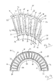
- a first embodiment of a stator 26 is shown.
- the stator disc 26 defines a plane and includes an inner ring 84 and a Outer ring 86. Between the inner ring 84 and the outer ring 86 extend in the radial direction Statorschaufeln 88, which are respectively connected via webs 90 with the inner ring 84 and the outer ring 86.
- the stator blades 88 are respectively rotated about the webs 90 and inclined to the plane defined by the stator disk 26 ( Fig. 2a ).
- the stator blades 88 are approximately trapezoidal in shape, wherein the base connected to the inner ring 84 is formed shorter than the side connected to the outer ring 86 base side.
- imprints 92 are introduced, which serve as stiffening elements and in particular stiffen the inner ring 84 relative to the outer ring 86.
- the embossments 92 are also shaped approximately trapezoidal and go in the area of the base sides of the trapezoidal shape in triangular transition regions 94 on.
- the legs of the trapezoidal embossing 92 extend in the radial direction and accordingly have a constant distance from the circumferentially oriented edges of the stator blades 88.
- the stator disc 26 is formed in one piece and made by means of a stamping bending process of a metal sheet.
- the impressions 92 of the stator blades 88 are also produced by means of the stamping bending process.
- the stator disc 26 covers an angular range of 180 ° and is thus semicircular ( Fig. 2b ).
- two stator disks 26 are respectively arranged in a plane to form a solid disk.
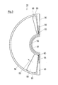
- Fig. 3 shows a second embodiment of a stator 26, which is semicircular or half-ring-shaped and thus covers an angular range of 180 °.
- Fig. 3 For example, only two stator blades 88 are shown, however, as in the first embodiment, further stator blades 88 are present, as indicated by the arrow 89.
- FIG. 3 In addition, two of the inner ring 84 and the outer ring 86 of the stator 26 connecting end webs 96 are shown, each defining the completion of the stator 26 in the circumferential direction.
- the end webs 96 are trapezoidal, wherein the legs of the trapezoidal shape each extend in the radial direction.
- the stator 26 according to Fig. 3 comprises a stiffening element, which is formed as a bead 98.
- the bead 98 begins in the radial direction approximately centrally in the one end web 96, extends from there to the semicircular inner ring 84, follows the inner ring 84 completely and also extends into the other end web 96 about half of it.
- the bead 98 is formed continuously and thus forms in plan view approximately the Greek letter Omega ( ⁇ ).
- the bead 98 protrudes upward from the plane defined by the stator disk 26 and may, for example, have a V-shaped, U-shaped, rectangular or round cross-section.
- the bead 98 counteracts a distortion of both the end webs 96 and the inner ring 84 and stiffened in this way the entire stator 26th
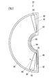
- FIG. 4 A third embodiment of a stator disk 26 is shown, which differs from the second embodiment in that the end webs 96 are rectangular.
- the bead 98 serving to stiffen the stator disk 26 extends only over a majority of the inner ring 84 from a central region of the one end web 96, but not along the other end web 96.
- the bead 98 forms approximately the shape of a sickle.
- Fig. 5 shows a fourth embodiment of a stator 26, which differs from the in Fig. 3 differs in that two beads 98 are provided, each extending approximately along the radially inner half of a terminal web 96 and continue along the inner ring 84 and cover each over an angular range of about 30 °. The two beads 98 are separated.
- Fig. 6 schematically shows the arrangement of a stator 26 according to the prior art between two rotor discs 24 which are coupled to the rotor shaft 22.
- the rotor shaft 22 facing inner ring 84 of the stator 26 is formed flat here. Radially outward, the stator blades 88, which are inclined to the plane, adjoin the inner ring 84.
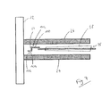
- Fig. 7 shows in contrast to Fig. 6 a stator according to the invention 26 which on the inner ring 84 has two double-right-angled bends 100, which serve to stiffen the stator 26. Seen in cross section, this results in a meandering course of the inner ring 84.
- the folds 100 reduces the axial gap 102 between the stator 26 and the adjacent rotor disks 24, whereby a backflow of molecules to be pumped is difficult, which reduces the conductance and thus the Efficiency of the turbomolecular pump 10 increases.
- stiffening elements shown can each also be combined with one another; in particular, the embossings 92 of the stator blades 88 can be combined according to FIG Fig. 2 and the beads 98 according to Fig. 3 to 5 be combined with each other. Instead of the beads 98 can also be bent 100, as in Fig. 7 shown to be used. Also additionally or alternatively, a further stiffening element may be provided on the outer ring 86, for example in the form of a closed circumferential Bead, which extends over the entire outer ring 86, the two end webs 96 and the entire inner ring 84.
Landscapes
- Engineering & Computer Science (AREA)
- Mechanical Engineering (AREA)
- General Engineering & Computer Science (AREA)
- Non-Positive Displacement Air Blowers (AREA)
Abstract
Description
- Die Erfindung betrifft eine Statorscheibe für eine Turbomolekularpumpe, wobei die Statorscheibe sich teilringförmig in einer Ebene erstreckt und einen Innenring und einen Außenring aufweist, welche durch Statorschaufeln miteinander verbunden sind.
- Turbomolekularpumpen dienen zur Erzeugung eines Vakuums, beispielsweise für Elektronenmikroskope oder Massenspektrometer. Dabei werden Gasteilchen von Rotorscheiben der Turbomolekularpumpe beschleunigt und von Statorscheiben in eine Vorzugsrichtung gelenkt, wodurch eine das Vakuum erzeugende Strömung entsteht. Zu diesem Zweck umfassen sowohl die Rotorscheiben als auch die Statorscheiben zu der Ebene schräg gestellte Schaufeln, die die Gasteilchen beschleunigen bzw. Ablenken.
- Eine Statorscheibe ist üblicherweise durch Distanzringe im Bereich ihres Außenrings fixiert, wenn die Statorscheibe in einer Turbomolekularpumpe verbaut ist. Der Bereich des Innenrings der Statorscheibe ist jedoch nicht fixiert. Insbesondere bei starker mechanischer Belastung der Statorscheibe, die beispielsweise beim Fluten eines evakuierten Raumes durch die Turbomolekularpumpe hindurch auftreten kann, kann es zu einer Verwindung bzw. Verbiegung der Statorscheibe und dadurch zu einer Kollision mit einer benachbarten Rotorscheibe kommen, weshalb ein gewisser axialer Abstand zwischen Stator- und Rotorscheiben eingehalten werden muss.
- Der Erfindung liegt die Aufgabe zugrunde, eine Statorscheibe für eine Turbomolekularpumpe anzugeben, welche eine verbesserte Steifigkeit aufweist.
- Diese Aufgabe wird durch eine Statorscheibe mit den Merkmalen des Anspruchs 1 und insbesondere dadurch gelöst, dass zumindest ein die Statorscheibe versteifendes Versteifungselement zwischen dem Innenring und dem Außenring vorgesehen ist.
- Der Erfindung liegt dabei die Erkenntnis zugrunde, dass eine Verbiegung der Statorscheibe, beispielsweise beim Fluten des evakuierten Raumes, im Bereich des Innenrings maximal ist. Im Bereich des Außenrings hingegen ist die Statorscheibe von Distanzringen eingespannt und kann sich dort nicht verbiegen. Durch die Anordnung des Versteifungselements zwischen Innen- und Außenring wird sozusagen die durch das Zusammenspiel von Distanzringen und Außenring der Statorscheibe hervorgerufene Steifigkeit im Bereich des Außenrings an den Innenring übertragen. Anders ausgedrückt wird mittels des zwischen Innen- und Außenring vorgesehenen Versteifungselements die Verbindung zwischen dem Innen-und dem Außenring versteift und der Innenring abgestützt. Auf diese Weise erhöht sich die axiale Biegesteifigkeit der Statorscheibe.
- Durch das Versteifungselement wird somit eine Verbiegung des Innenrings unter Belastung minimiert, sodass der axiale Abstand zwischen den Stator- und Rotorscheiben verringert werden kann. Dadurch können im Ergebnis kompaktere Turbomolekularpumpen geschaffen werden.
- Vorteilhafte Ausführungsformen der Erfindung sind den Unteransprüchen, der Beschreibung und den Zeichnungen zu entnehmen.
- Gemäß einer bevorzugten Ausführungsform ist ein Versteifungselement an einer Statorschaufel angeordnet. Auf die Statorschaufel kann z.B. zumindest ein separat ausgebildetes Versteifungselement aufgebracht sein, z.B. aufgeklebt oder aufgeschweißt sein. Alternativ kann die Statorschaufel selbst das Versteifungselement bilden, indem sie beispielsweise mit einer konkaven oder konvexen Krümmung versehen ist, die über die Länge der Statorscheibe verläuft.
- Bevorzugt ist ein Versteifungselement durch eine Sicke und/oder eine Abkantung gebildet. Wird die Statorscheibe z.B. als Stanzbiegeteil insbesondere einstückig aus einem Blech hergestellt, lässt sich die Formung von Sicken und/oder Abkantungen auf einfache Weise in den Herstellungsprozess integrieren und idealerweise in einem Stanzbiegeschritt herstellen. Anstelle einer Sicke kann auch eine Bördelkante als Versteifungselement vorgesehen sein.
- Alternativ kann das Versteifungselement auch durch zusätzlich aufgebrachtes Material gebildet sein, welches beispielsweise durch Aufkleben oder Aufschweißen an der Statorscheibe angebracht wird.
- Besonders bevorzugt ist ein Versteifungselement an einem den Innen- und Außenring verbindenden Abschlusssteg angeordnet. Der Abschlusssteg erstreckt sich dabei zwischen Innen- und Außenring, dient aber nicht als Statorschaufel und liegt somit in der von der Statorscheibe definierten Ebene.
- Insbesondere ist der Abschlusssteg an einem Ende der teilringförmigen Statorscheibe angeordnet. Bevorzugt ist die Statorscheibe halbring- bzw. halbkreisförmig mit zwei Abschlussstegen ausgebildet. Bei der Montage der Turbomolekularpumpe werden dann zwei halbkreisförmige Statorscheiben zusammengefügt, um eine Vollscheibe zu bilden, wobei jeweils zwei Abschlussstege aneinander angrenzen.
- Die Anordnung der versteiften Abschlussstege an den Enden der Statorscheibe hat den Vorteil, dass insbesondere die Enden des Innenrings wirksam gegen Verbiegung geschützt werden, welche den stärksten Belastungen ausgesetzt sind.
- Gemäß einer weiteren vorteilhaften Ausführungsform erstreckt sich ein Versteifungselement zumindest bereichsweise auch entlang des Innenrings. Auf diese Weise wird auch der Innenring selbst gegen Verbiegung geschützt. Zugleich ergibt sich der Vorteil, dass der Innenring durch das Versteifungselement verdickt werden kann, wodurch sich ein axialer Spalt zwischen der Statorscheibe und den angrenzenden Rotorscheiben verringert. Durch das reduzierte Spaltmaß wird der Leitwert verringert und eine Rückströmung von zu pumpenden Molekülen vermindert.
- Insbesondere kann das sich entlang des Innenrings erstreckende Versteifungselement durch zwei nebeneinander angeordnete Sicken gebildet sein, wodurch sich ein mäanderförmiger Querschnitt der Statorscheibe in diesem Bereich ergibt.
- Gemäß einer weiteren vorteilhaften Ausführungsform erstreckt sich ein Versteifungselement zumindest bereichsweise auch entlang des Außenrings. Dadurch kann die Statorscheibe auch im Bereich des Außenrings zusätzlich versteift werden.
- Generell kann die Statorscheibe halbkreisförmig ausgebildet sein, d.h. also mit einem Winkelbereich von 180°.
- Gemäß einer alternativen Ausführungsform deckt die Statorscheibe einen Winkelbereich von größer 180° ab, beispielsweise von 190°. Sind zwei die Rotorwelle einer Turbomolekularpumpe im montierten Zustand umgebende Statorscheiben jeweils mit einem Winkelbereich von 190° ausgebildet, so können diese Statorscheiben an ihren zueinander weisenden Enden jeweils über einen Winkelbereich von 10° aufeinander liegen, d.h. also sich überlappen, wodurch eine zusätzliche Versteifung der Statorscheiben erreicht wird.
- Die axiale Biegesteifigkeit einer Statorscheibe wird noch weiter erhöht, wenn die Statorscheibe ein Versteifungselement in einem zur Anlage an einer weiteren Statorscheibe vorgesehenen Überlappungsbereich aufweist. Beispielsweise kann der Überlappungsbereich durch einen Abschlusssteg gebildet sein. Im montierten Zustand der Statorscheiben können die Überlappungsbereiche zweier Statorscheiben in der axialen Richtung gesehen übereinander liegen, um eine zusätzliche Versteifung der Statorscheiben zu bewirken.
- Die Versteifungselemente in dem Überlappungsbereich können zudem derart ausgebildet sein, dass sie ineinander eingreifen und die Position der Statorscheiben relativ zueinander in der Ebene festlegen.
- Besonders bevorzugt ist ein Versteifungselement sowohl an dem Abschlusssteg als auch an dem Innenring angeordnet und durchgängig ausgebildet. Hierdurch kann eine auf den Innenring wirkende Kraft besonders gut auf den Abschlusssteg übertragen werden, welcher von dem fixierten Außenring gehalten wird. Auf diese Weise wird der Innenring noch besser gegen Verbiegung geschützt.
- Ebenfalls bevorzugt weist die Statorscheibe zwei Abschlussstege auf, wobei sich ein Versteifungselement von einem Bereich des ersten Abschlussstegs über den Innenring bis hin zu einem Bereich des zweiten Abschlussstegs erstreckt. Eine auf den Innenring wirkende Kraft kann somit an zwei Stellen durch das Versteifungselement an den Außenring übertragen werden.
- Allgemein sind sämtliche der voranstehend genannten Versteifungselemente miteinander kombinierbar und verbindbar und insbesondere durchgängig ausbildbar.
- Die Erfindung umfasst weiterhin ein Verfahren zur Herstellung einer für eine Turbomolekularpumpe vorgesehenen Statorscheibe, welche sich teilringförmig in einer Ebene erstreckt und einen Innenring und einen Außenring aufweist, welche durch Statorschaufeln miteinander verbunden sind, bei welchem Verfahren zumindest ein die Statorscheibe versteifendes Versteifungselement zwischen dem Innenring und dem Außenring ausgebildet wird. Beispielsweise können das Versteifungselement bzw. die Versteifungselemente, der Innenring und der Außenring sowie die Schaufeln der Statorscheibe in ein und denselben Prozessschritten und damit besonders wirtschaftlich hergestellt werden.
- Des Weiteren betrifft die Erfindung auch eine Turbomolekularpumpe mit zumindest einer Statorscheibe der voranstehend beschriebenen Art, für welche die vorgenannten Vorteile und Weiterbildungen der Statorscheibe entsprechend gelten.
- Nachfolgend wird die Erfindung anhand möglicher Ausführungsformen unter Bezugnahme auf die beigefügten Zeichnungen beschrieben. Es zeigen:
- Fig. 1
- eine erfindungsgemäße Turbomolekularpumpe in Querschnittsansicht;
- Fig. 2
- eine erste Ausführungsform einer erfindungsgemäßen Statorscheibe in (a) bereichsweiser perspektivischer Ansicht und (b) Draufsicht;
- Fig. 3
- eine Draufsicht auf eine zweite Ausführungsform einer erfindungsgemäßen Statorscheibe;
- Fig. 4
- eine Draufsicht auf eine dritte Ausführungsform einer erfindungsgemäßen Statorscheibe;
- Fig. 5
- eine Draufsicht auf eine vierte Ausführungsform einer erfindungsgemäßen Statorscheibe;
- Fig. 6
- eine Querschnittsansicht einer Anordnung einer Statorscheibe gemäß dem Stand der Technik zwischen zwei benachbarten Rotorscheiben; und
- Fig. 7
- eine Querschnittsansicht einer Anordnung einer erfindungsgemäßen Statorscheibe zwischen zwei benachbarten Rotorscheiben.
- Die in
Fig. 1 gezeigte Turbomolekularpumpe 10 umfasst einen von einem Einlassflansch 12 umgebenen Pumpeneinlass 14 sowie mehrere Pumpstufen zur Förderung des an dem Pumpeneinlass 14 anstehenden Gases zu einem inFig. 1 nicht dargestellten Pumpenauslass. In einem Gehäuse 16 der Turbomolekularpumpe 10 ist ein Rotor 18 mit einer um eine Rotationsachse 20 drehbar gelagerten Rotorwelle 22 angeordnet. - Zur Erzeugung einer Pumpwirkung umfasst die Turbomolekularpumpe 10 mehrere pumpwirksam miteinander in Serie geschaltete turbomolekulare Pumpstufen mit mehreren an der Rotorwelle 22 befestigten Rotorscheiben 24 und in axialer Richtung zwischen den Rotorscheiben 24 angeordneten Statorscheiben 26. Die Statorscheiben 26 sind durch Distanzringe 28 in einem gewünschten axialen Abstand zueinander gehalten.
- Des Weiteren sind drei in radialer Richtung ineinander angeordnete und pumpwirksam miteinander in Serie geschaltete Holweckpumpstufen vorgesehen. Der rotorseitige Teil der Holweckpumpstufen umfasst eine mit der Rotorwelle 22 verbundene Rotornabe 30 und zwei an der Rotornabe 30 befestigte und von dieser getragene zylindermantelförmige Holweckrotorhülsen 32, 34, die koaxial zu der Rotationsachse 22 orientiert und in radialer Richtung ineinander geschachtelt sind. Ferner sind zwei zylindermantelförmige Holweckstatorhülsen 36, 38 vorgesehen, die ebenfalls koaxial zu der Rotationsachse 22 orientiert und in radialer Richtung ineinander geschachtelt sind.
- Die pumpaktiven Oberflächen der Holweckpumpstufen sind jeweils durch die einander unter Ausbildung eines engen radialen Holweckspalts gegenüber liegenden radialen Mantelflächen jeweils einer Holweckrotorhülse 32, 34 und einer Holweckstatorhülse 36, 38 gebildet. Dabei ist jeweils eine der pumpaktiven Oberflächen glatt ausgebildet - vorwiegend diejenige der Holweckrotorhülse 32, 34 - und die gegenüberliegende pumpaktive Oberfläche der Holweckstatorhülse 36, 38 weist eine Strukturierung mit schraubenlinienförmig um die Rotationsachse 22 herum in axialer Richtung verlaufenden Nuten auf, in denen bei der Rotation des Rotors 18 das Gas vorangetrieben und dadurch gepumpt wird.
- Die drehbare Lagerung der Rotorwelle 22 wird durch ein Wälzlager 40 im Bereich des Pumpenauslasses und ein Permanentmagnetlager 42 im Bereich des Pumpeneinlasses 14 bewirkt.
- Das Permanentmagnetlager 42 umfasst eine rotorseitige Lagerhälfte 44 und eine statorseitige Lagerhälfte 46, welche jeweils einen Ringstapel aus mehreren in axialer Richtung aufeinander gestapelten permanentmagnetischen Ringen 48, 50 umfassen, wobei sich die Magnetringe 48, 50 unter Ausbildung eines radialen Lagerspalts 52 gegenüberliegen.
- Innerhalb des Magnetlagers 42 ist ein Not- bzw. Fanglager 54 vorgesehen, welches als ungeschmiertes Wälzlager ausgebildet ist und im normalen Betrieb der Turbomolekularpumpe 10 ohne Berührung leerläuft und erst bei einer übermäßigen radialen Auslenkung des Rotors 18 gegenüber dem Stator in Eingriff gelangt, um einen radialen Anschlag für den Rotor 18 zu bilden, der eine Kollision der rotorseitigen Strukturen mit den statorseitigen Strukturen verhindert. Das Notlager 54 definiert somit die maximale radiale Auslenkung des Rotors 18.
- Im Bereich des Wälzlagers 40 ist an der Rotorwelle 22 eine konische Spritzmutter 56 mit einem zu dem Wälzlager 40 hin zunehmenden Außendurchmesser vorgesehen. Die Spritzmutter 56 steht mit zumindest einem Abstreifer eines mehrere aufeinander gestapelte saugfähige Scheiben 58 umfassenden Betriebsmittelspeichers in gleitendem Kontakt, welche mit einem Betriebsmittel wie z.B. einem Schmiermittel für das Wälzlager 40 getränkt sind.
- Im Betrieb der Turbomolekularpumpe 10 wird das Betriebsmittel durch kapillare Wirkung von dem Betriebsmittelspeicher über den Abstreifer auf die rotierende Spritzmutter 56 übertragen und infolge der Zentrifugalkraft entlang der Spritzmutter in Richtung des größer werdenden Außendurchmessers der Spritzmutter 56 zu dem Wälzlager 40 hin gefördert, wo es zum Beispiel eine schmierende Funktion erfüllt.
- Die Turbomolekularpumpe 10 umfasst einen Motorraum 60, in den sich die Rotorwelle 22 hinein erstreckt. Der Motorraum 60 ist im Bereich des Eintritts der Rotorwelle 22 durch eine Siegbahnstufe 62 gegenüber einem Arbeits- bzw. Schöpfraum der Turbomolekularpumpe 10 abgedichtet. Ein Sperrgaseinlass 64 ermöglicht die Zuführung eines Sperrgases in den Motorraum 60.
- In dem Motorraum 60 ist ein Antriebsmotor 66 angeordnet, welcher zum drehenden Antreiben des Rotors 18 dient. Der Antriebsmotor 66 umfasst einen Motorstator 68 mit einem Kern 70 und mit mehreren in
Fig. 1 nur schematisch dargestellten Spulen 72, die in an der radialen Innenseite des Kerns 70 vorgesehenen Nuten des Kerns 70 festgelegt sind. Der Kern 70 besteht aus einem Blechpaket mit mehreren in axialer Richtung aufeinander gestapelten Blechscheiben aus einem weichmagnetischen Material. - Der Läufer des Antriebsmotors 77, welcher auch als Anker bezeichnet wird, ist durch die Rotorwelle 22 gebildet, die sich durch den Motorstator 68 hindurch erstreckt. Auf dem sich durch den Motorstator 68 hindurch erstreckenden Abschnitt der Rotorwelle 22 ist radial außenseitig eine Permanentmagnetanordnung 74 festgelegt. Zwischen dem Motorstator 68 und dem sich durch den Motorstator 68 hindurch erstreckenden Abschnitt der Rotorwelle 22 ist ein radialer Motorspalt 76 ausgebildet, über den sich der Motorstator 68 und die Permanentmagnetanordnung 74 zur Übertragung des Antriebsmoments magnetisch beeinflussen.
- Die Permanentmagnetanordnung 74 ist an der Rotorwelle 22 mittels Kleben und/oder Schrumpfen und/oder Aufpressen fixiert. Die Permanentmagnetanordnung 74 umfasst einen weichmagnetischen Rückschluss 75a aus Eisenblechen oder aus massivem Eisen sowie einen Permanentmagneten 75b. Eine Kapselung 80, die als CFK- oder Edelstahlhülse ausgebildet ist, umgibt die Permanentmagnetanordnung 74 an deren radialer Außenseite und dichtet diese gegenüber dem Motorspalt 76 ab. Auf der Rotorwelle 22 ist ferner ein Wuchtring 78 mittels Kleben und/oder Schrumpfen und/oder Aufpressen angebracht, welcher Gewindebohrungen zur Aufnahme von Wuchtgewichten aufweist. Der Wuchtring 78 besitzt keine direkte mechanische Verbindung zur Permanentmagnetanordnung 74, um keine axialen Zwangskräfte auf die Permanentmagnetanordnung 74 zu übertragen.
- Eine Steuer- und Stromversorgungseinheit 82 ist dazu eingerichtet, den Antriebsmotor 66 während des Betriebs der Turbomolekularpumpe 10 mit elektrischer Energie zu versorgen.
- In
Fig. 2 ist eine erste Ausführungsform einer Statorscheibe 26 gezeigt. Die Statorscheibe 26 definiert eine Ebene und umfasst einen Innenring 84 und einen Außenring 86. Zwischen dem Innenring 84 und dem Außenring 86 erstrecken sich in radialer Richtung Statorschaufeln 88, welche jeweils über Stege 90 mit dem Innenring 84 und dem Außenring 86 verbunden sind. Die Statorschaufeln 88 sind jeweils um die Stege 90 gedreht und zu der von der Statorscheibe 26 definierten Ebene schräg gestellt (Fig. 2a ). Zudem sind die Statorschaufeln 88 in etwa trapezförmig geformt, wobei die mit dem Innenring 84 verbundene Grundseite kürzer ausgebildet ist als die mit dem Außenring 86 verbundene Grundseite. - In die Statorschaufeln 88 sind Prägungen 92 eingebracht, die als Versteifungselemente dienen und insbesondere den Innenring 84 gegenüber dem Außenring 86 versteifen. Die Prägungen 92 sind ebenfalls etwa trapezförmig ausgeformt und gehen im Bereich der Grundseiten der Trapezform in dreieckförmige Übergangsbereiche 94 über. Die Schenkel der trapezförmigen Prägung 92 verlaufen in radialer Richtung und weisen dementsprechend einen gleichbleibenden Abstand zu den in Umfangsrichtung orientierten Rändern der Statorschaufeln 88 auf.
- Die Statorscheibe 26 ist einstückig ausgebildet und mittels eines Stanzbiegeverfahrens aus einem Blech hergestellt. Mittels des Stanzbiegeverfahrens werden auch die Prägungen 92 der Statorschaufeln 88 erzeugt.
- Die Statorscheibe 26 überdeckt einen Winkelbereich von 180° und ist somit halbkreisförmig ausgebildet (
Fig. 2b ). In der Turbomolekularpumpe 10 werden jeweils zwei Statorscheiben 26 in einer Ebene angeordnet, um eine Vollscheibe zu bilden. -
Fig. 3 zeigt eine zweite Ausführungsform einer Statorscheibe 26, die halbkreisförmig bzw. halbringförmig ausgebildet ist und somit einen Winkelbereich von 180° überdeckt. InFig. 3 sind beispielhaft lediglich zwei Statorschaufeln 88 dargestellt, jedoch sind wie bei der ersten Ausführungsform weitere Statorschaufeln 88 vorhanden, wie durch den Pfeil 89 angedeutet ist. - In
Fig. 3 sind außerdem zwei den Innenring 84 und den Außenring 86 der Statorscheibe 26 verbindende Abschlussstege 96 gezeigt, die jeweils den Abschluss der Statorscheibe 26 in Umfangsrichtung definieren. Die Abschlussstege 96 sind trapezförmig ausgebildet, wobei die Schenkel der Trapezform jeweils in radialer Richtung verlaufen. - Die Statorscheibe 26 gemäß
Fig. 3 umfasst ein Versteifungselement, welches als Sicke 98 ausgebildet ist. Die Sicke 98 beginnt in radialer Richtung gesehen etwa mittig in dem einen Abschlusssteg 96, erstreckt sich von dort zu dem halbkreisförmigen Innenring 84, folgt dem Innenring 84 vollständig und erstreckt sich in den anderen Abschlusssteg 96 ebenfalls ungefähr bis zu dessen Hälfte hinein. Die Sicke 98 ist dabei durchgängig ausgebildet und formt so in der Draufsicht annähernd den griechischen Buchstaben Omega (Ω). - Die Sicke 98 ragt aus der durch die Statorscheibe 26 definierten Ebene nach oben hervor und kann beispielsweise einen V-förmigen, U-förmigen, rechteckigen oder runden Querschnitt aufweisen.
- Die Sicke 98 wirkt einer Verwindung sowohl der Abschlussstege 96 als auch des Innenrings 84 entgegen und versteift auf diese Weise die gesamte Statorscheibe 26.
- In
Fig. 4 ist eine dritte Ausführungsform einer Statorscheibe 26 gezeigt, die sich von der zweiten Ausführungsform darin unterscheidet, dass die Abschlussstege 96 rechteckig ausgebildet sind. Zudem verläuft die zur Versteifung der Statorscheibe 26 dienende Sicke 98 lediglich von einem mittleren Bereich des einen Abschlussstegs 96 ausgehend über einen Großteil des Innenrings 84, nicht jedoch entlang des anderen Abschlussstegs 96. Somit bildet die Sicke 98 in der Draufsicht etwa die Form einer Sichel. -
Fig. 5 zeigt eine vierte Ausführungsform einer Statorscheibe 26, die sich von der inFig. 3 gezeigten Statorscheibe dadurch unterscheidet, dass zwei Sicken 98 vorgesehen sind, die sich jeweils etwa entlang der radial inneren Hälfte eines Abschlussstegs 96 erstrecken und sich entlang des Innenrings 84 fortsetzen und diesen jeweils über einen Winkelbereich von etwa 30° überdecken. Die beiden Sicken 98 sind voneinander getrennt. -
Fig. 6 zeigt schematisch die Anordnung einer Statorscheibe 26 gemäß dem Stand der Technik zwischen zwei Rotorscheiben 24, die mit der Rotorwelle 22 gekoppelt sind. Der zur Rotorwelle 22 weisende Innenring 84 der Statorscheibe 26 ist hier flach ausgebildet. Radial nach außen schließen sich die zur Ebene schräg gestellten Statorschaufeln 88 an den Innenring 84 an. -
Fig. 7 zeigt im Unterschied zuFig. 6 eine erfindungsgemäße Statorscheibe 26, welche an dem Innenring 84 zwei doppelt rechtwinklige Abkantungen 100 aufweist, die zur Versteifung der Statorscheibe 26 dienen. Im Querschnitt gesehen ergibt sich somit ein mäanderförmiger Verlauf des Innenrings 84. Durch die Abkantungen 100 verkleinert sich das axiale Spaltmaß 102 zwischen der Statorscheibe 26 und den benachbarten Rotorscheiben 24, wodurch ein Rückströmen von zu pumpenden Molekülen erschwert wird, was den Leitwert reduziert und so die Effizienz der Turbomolekularpumpe 10 steigert. - Generell ist anzumerken, dass die verschiedenen gezeigten Ausführungsformen der Versteifungselemente jeweils auch miteinander kombinierbar sind, insbesondere können die Prägungen 92 der Statorschaufeln 88 gemäß
Fig. 2 und die Sicken 98 gemäßFig. 3 bis 5 miteinander kombiniert werden. Anstelle der Sicken 98 können jeweils auch Abkantungen 100, wie inFig. 7 gezeigt, verwendet werden. Ebenfalls kann zusätzlich oder alternativ ein weiteres Versteifungselement an dem Außenring 86 vorgesehen sein, beispielsweise in Form einer geschlossen umlaufenden Sicke, die sich über den kompletten Außenring 86, die zwei Abschlussstege 96 und den kompletten Innenring 84 erstreckt. -
- 10
- Turbomolekularpumpe
- 12
- Einlassflansch
- 14
- Pumpeneinlass
- 16
- Gehäuse
- 18
- Rotor
- 20
- Rotationsachse
- 22
- Rotorwelle
- 24
- Rotorscheibe
- 26
- Statorscheibe
- 28
- Distanzring
- 30
- Rotornabe
- 32
- Holweckrotorhülse
- 34
- Holweckrotorhülse
- 36, 38
- Holweckstatorhülse
- 40
- Wälzlager
- 42
- Permanentmagnetlager
- 44
- Rotorseitige Lagerhälfte
- 46
- Statorseitige Lagerhälfte
- 48
- Magnetring
- 50
- Magnetring
- 52
- Lagerspalt
- 54
- Fanglager
- 56
- Spritzmutter
- 58
- saugfähige Scheibe
- 60
- Motorraum
- 62
- Siegbahnstufe
- 64
- Sperrgaseinlass
- 66
- Antriebsmotor
- 68
- Motorstator
- 70
- Kern
- 72
- Spule
- 74
- Permanentmagnetanordnung
- 75a
- weichmagnetischer Rückschluss
- 75b
- Permanentmagnet
- 76
- Motorspalt
- 78
- Wuchtring
- 80
- Kapselung
- 82
- Steuer- und Stromversorgungseinheit
- 84
- Innenring
- 86
- Außenring
- 88
- Statorschaufel
- 89
- Pfeil
- 90
- Steg
- 92
- Prägung
- 94
- Übergangsbereich
- 96
- Abschlusssteg
- 98
- Sicke
- 100
- Abkantung
- 102
- Spaltmaß
Claims (12)
- Statorscheibe (26) für eine Turbomolekularpumpe (10), wobei die Statorscheibe (26) sich teilringförmig in einer Ebene erstreckt und einen Innenring (84) und einen Außenring (86) aufweist, welche durch Statorschaufeln (88) miteinander verbunden sind,
dadurch gekennzeichnet, dass
zumindest ein die Statorscheibe (26) versteifendes Versteifungselement (92, 98, 100) zwischen dem Innenring (84) und dem Außenring (86) vorgesehen ist. - Statorscheibe (26) nach Anspruch 1,
dadurch gekennzeichnet, dass
ein Versteifungselement (92, 98, 100) an einer Statorschaufel (88) angeordnet ist. - Statorscheibe (26) nach Anspruch 2,
dadurch gekennzeichnet, dass
ein Versteifungselement durch eine Sicke (98) und/oder eine Abkantung (100) gebildet ist. - Statorscheibe (26) nach einem der vorstehenden Ansprüche,
dadurch gekennzeichnet, dass
ein Versteifungselement (92, 98, 100) an einem den Innen- und Außenring (84, 86) verbindenden Abschlusssteg (96) angeordnet ist. - Statorscheibe (26) nach einem der vorstehenden Ansprüche,
dadurch gekennzeichnet, dass
sich ein Versteifungselement (92, 98, 100) zumindest bereichsweise auch entlang des Innenrings (84) erstreckt. - Statorscheibe (26) nach einem der vorstehenden Ansprüche,
dadurch gekennzeichnet, dass
sich ein Versteifungselement (92, 98, 100) zumindest bereichsweise auch entlang des Außenrings (86) erstreckt. - Statorscheibe (26) nach einem der vorstehenden Ansprüche,
gekennzeichnet durch
ein Versteifungselement (92, 98, 100) in einem zur Anlage an einer weiteren Statorscheibe (26) vorgesehenen Überlappungsbereich. - Statorscheibe (26) nach einem der vorstehenden Ansprüche,
dadurch gekennzeichnet, dass
die Statorscheibe (26) einen Winkelbereich von größer 180°, beispielsweise von 190°, überdeckt. - Statorscheibe (26) nach einem der Ansprüche 4 bis 8,
dadurch gekennzeichnet, dass
ein Versteifungselement (92, 98, 100) an dem Abschlusssteg (96) und an dem Innenring (84) angeordnet ist und durchgängig ausgebildet ist. - Statorscheibe (26) nach einem der Ansprüche 4 bis 9,
dadurch gekennzeichnet, dass
die Statorscheibe (26) zwei Abschlussstege (96) aufweist und sich ein Versteifungselement (92, 98, 100) von einem Bereich des ersten Abschlussstegs (96) über den Innenring (84) bis hin zu einem Bereich des zweiten Abschlussstegs (96) erstreckt. - Verfahren zur Herstellung einer für eine Turbomolekularpumpe (10) vorgesehenen Statorscheibe (26), welche sich teilringförmig in einer Ebene erstreckt und einen Innenring (84) und einen Außenring (86) aufweist, welche durch Statorschaufeln 888) miteinander verbunden sind,
dadurch gekennzeichnet, dass
zumindest ein die Statorscheibe (26) versteifendes Versteifungselement (92, 98, 100) zwischen dem Innenring (84) und dem Außenring (86) ausgebildet wird. - Turbomolekularpumpe (10) mit zumindest einer Statorscheibe (26) nach einem der Ansprüche 1 bis 10.
Applications Claiming Priority (1)
| Application Number | Priority Date | Filing Date | Title |
|---|---|---|---|
| DE102013114576.0A DE102013114576A1 (de) | 2013-12-19 | 2013-12-19 | Statorscheibe |
Publications (2)
| Publication Number | Publication Date |
|---|---|
| EP2886869A1 true EP2886869A1 (de) | 2015-06-24 |
| EP2886869B1 EP2886869B1 (de) | 2018-09-05 |
Family
ID=51904735
Family Applications (1)
| Application Number | Title | Priority Date | Filing Date |
|---|---|---|---|
| EP14192849.9A Active EP2886869B1 (de) | 2013-12-19 | 2014-11-12 | Statorscheibe |
Country Status (3)
| Country | Link |
|---|---|
| EP (1) | EP2886869B1 (de) |
| JP (1) | JP6027601B2 (de) |
| DE (1) | DE102013114576A1 (de) |
Cited By (1)
| Publication number | Priority date | Publication date | Assignee | Title |
|---|---|---|---|---|
| EP3611381A1 (de) * | 2018-08-13 | 2020-02-19 | Pfeiffer Vacuum Gmbh | Verfahren zur herstellung einer vakuumpumpe |
Citations (4)
| Publication number | Priority date | Publication date | Assignee | Title |
|---|---|---|---|---|
| EP0967395A2 (de) * | 1998-06-23 | 1999-12-29 | Seiko Seiki Kabushiki Kaisha | Turbomolekularpumpe |
| JP2006046074A (ja) * | 2004-07-30 | 2006-02-16 | Boc Edwards Kk | 真空ポンプ |
| DE102010052659A1 (de) * | 2010-11-26 | 2012-05-31 | Pfeiffer Vacuum Gmbh | Turbomolekularpumpe |
| DE102011108115A1 (de) * | 2011-07-20 | 2013-01-24 | Pfeiffer Vacuum Gmbh | Turbomolekularpumpe |
Family Cites Families (3)
| Publication number | Priority date | Publication date | Assignee | Title |
|---|---|---|---|---|
| JP4527966B2 (ja) * | 2003-05-01 | 2010-08-18 | 株式会社大阪真空機器製作所 | 分子ポンプ |
| DE102010052660A1 (de) * | 2010-11-26 | 2012-05-31 | Pfeiffer Vacuum Gmbh | Turbomolekularpumpe |
| JP3183571U (ja) * | 2013-03-07 | 2013-05-23 | 株式会社島津製作所 | ターボ分子ポンプ |
-
2013
- 2013-12-19 DE DE102013114576.0A patent/DE102013114576A1/de not_active Withdrawn
-
2014
- 2014-11-12 EP EP14192849.9A patent/EP2886869B1/de active Active
- 2014-12-11 JP JP2014250730A patent/JP6027601B2/ja active Active
Patent Citations (4)
| Publication number | Priority date | Publication date | Assignee | Title |
|---|---|---|---|---|
| EP0967395A2 (de) * | 1998-06-23 | 1999-12-29 | Seiko Seiki Kabushiki Kaisha | Turbomolekularpumpe |
| JP2006046074A (ja) * | 2004-07-30 | 2006-02-16 | Boc Edwards Kk | 真空ポンプ |
| DE102010052659A1 (de) * | 2010-11-26 | 2012-05-31 | Pfeiffer Vacuum Gmbh | Turbomolekularpumpe |
| DE102011108115A1 (de) * | 2011-07-20 | 2013-01-24 | Pfeiffer Vacuum Gmbh | Turbomolekularpumpe |
Cited By (1)
| Publication number | Priority date | Publication date | Assignee | Title |
|---|---|---|---|---|
| EP3611381A1 (de) * | 2018-08-13 | 2020-02-19 | Pfeiffer Vacuum Gmbh | Verfahren zur herstellung einer vakuumpumpe |
Also Published As
| Publication number | Publication date |
|---|---|
| EP2886869B1 (de) | 2018-09-05 |
| JP2015117699A (ja) | 2015-06-25 |
| DE102013114576A1 (de) | 2015-06-25 |
| JP6027601B2 (ja) | 2016-11-16 |
Similar Documents
| Publication | Publication Date | Title |
|---|---|---|
| EP2829734B1 (de) | Vakuumpumpe | |
| EP2503104B1 (de) | Turbomaschine | |
| EP0856108B1 (de) | Reibungsvakuumpumpe mit zwischeneinlass | |
| DE102018128521A1 (de) | Stützeinrichtung für einen Rotor einer fremderregten Innenläufer-Synchronmaschine, Rotor, fremderregte Innenläufer-Synchronmaschine sowie Kraftfahrzeug | |
| DE102012003680A1 (de) | Vakuumpumpe | |
| WO2010115539A1 (de) | Elektromotor | |
| EP2863063B1 (de) | Vakuumpumpe | |
| EP1498612B1 (de) | Turbomolekularpumpe | |
| WO2019219270A1 (de) | Seitenkanalverdichter für ein brennstoffzellensystem zur förderung und/oder verdichtung von einem gasförmigen medium | |
| EP1731766B1 (de) | Statorscheibe für Turbomolekularpumpe | |
| DE102018220007A1 (de) | Seitenkanalverdichter für ein Brennstoffzellensystem zur Förderung und/oder Verdichtung von einem gasförmigen Medium | |
| EP2886869B1 (de) | Statorscheibe | |
| EP2913533B1 (de) | Statorscheibe | |
| EP3107192B1 (de) | Vakuumpumpe | |
| EP1918588B1 (de) | Statorscheibe für eine Turbomolekularpumpe | |
| EP2565464B1 (de) | Vakuumpumpe | |
| EP3734078B1 (de) | Turbomolekularpumpe und verfahren zur herstellung einer statorscheibe für eine solche | |
| EP3683447B1 (de) | Vakuumpumpe | |
| EP3133290B1 (de) | Vakuumpumpe | |
| EP4325061B1 (de) | Turbomolekularvakuumpumpe | |
| DE102019214279A1 (de) | Seitenkanalverdichter für ein Brennstoffzellensystem zur Förderung und/oder Verdichtung eines gasförmigen Mediums | |
| EP2894348B1 (de) | Statorscheibe | |
| WO2019057712A1 (de) | Elektrische medienspaltmaschine für einen verdichter und/oder turbine, verdichter und/oder turbine | |
| EP3561307B1 (de) | Vakuumpumpe mit einem einlassflansch und einem lagerträger im einlass | |
| EP3096020B1 (de) | Vakuumpumpe |
Legal Events
| Date | Code | Title | Description |
|---|---|---|---|
| PUAI | Public reference made under article 153(3) epc to a published international application that has entered the european phase |
Free format text: ORIGINAL CODE: 0009012 |
|
| 17P | Request for examination filed |
Effective date: 20141112 |
|
| AK | Designated contracting states |
Kind code of ref document: A1 Designated state(s): AL AT BE BG CH CY CZ DE DK EE ES FI FR GB GR HR HU IE IS IT LI LT LU LV MC MK MT NL NO PL PT RO RS SE SI SK SM TR |
|
| AX | Request for extension of the european patent |
Extension state: BA ME |
|
| R17P | Request for examination filed (corrected) |
Effective date: 20151211 |
|
| RBV | Designated contracting states (corrected) |
Designated state(s): AL AT BE BG CH CY CZ DE DK EE ES FI FR GB GR HR HU IE IS IT LI LT LU LV MC MK MT NL NO PL PT RO RS SE SI SK SM TR |
|
| STAA | Information on the status of an ep patent application or granted ep patent |
Free format text: STATUS: EXAMINATION IS IN PROGRESS |
|
| 17Q | First examination report despatched |
Effective date: 20170724 |
|
| GRAP | Despatch of communication of intention to grant a patent |
Free format text: ORIGINAL CODE: EPIDOSNIGR1 |
|
| STAA | Information on the status of an ep patent application or granted ep patent |
Free format text: STATUS: GRANT OF PATENT IS INTENDED |
|
| INTG | Intention to grant announced |
Effective date: 20180321 |
|
| GRAS | Grant fee paid |
Free format text: ORIGINAL CODE: EPIDOSNIGR3 |
|
| GRAA | (expected) grant |
Free format text: ORIGINAL CODE: 0009210 |
|
| STAA | Information on the status of an ep patent application or granted ep patent |
Free format text: STATUS: THE PATENT HAS BEEN GRANTED |
|
| AK | Designated contracting states |
Kind code of ref document: B1 Designated state(s): AL AT BE BG CH CY CZ DE DK EE ES FI FR GB GR HR HU IE IS IT LI LT LU LV MC MK MT NL NO PL PT RO RS SE SI SK SM TR |
|
| REG | Reference to a national code |
Ref country code: GB Ref legal event code: FG4D Free format text: NOT ENGLISH |
|
| REG | Reference to a national code |
Ref country code: CH Ref legal event code: EP |
|
| REG | Reference to a national code |
Ref country code: AT Ref legal event code: REF Ref document number: 1038140 Country of ref document: AT Kind code of ref document: T Effective date: 20180915 |
|
| REG | Reference to a national code |
Ref country code: IE Ref legal event code: FG4D Free format text: LANGUAGE OF EP DOCUMENT: GERMAN |
|
| REG | Reference to a national code |
Ref country code: DE Ref legal event code: R096 Ref document number: 502014009368 Country of ref document: DE |
|
| REG | Reference to a national code |
Ref country code: NL Ref legal event code: MP Effective date: 20180905 |
|
| REG | Reference to a national code |
Ref country code: LT Ref legal event code: MG4D |
|
| PG25 | Lapsed in a contracting state [announced via postgrant information from national office to epo] |
Ref country code: LT Free format text: LAPSE BECAUSE OF FAILURE TO SUBMIT A TRANSLATION OF THE DESCRIPTION OR TO PAY THE FEE WITHIN THE PRESCRIBED TIME-LIMIT Effective date: 20180905 Ref country code: SE Free format text: LAPSE BECAUSE OF FAILURE TO SUBMIT A TRANSLATION OF THE DESCRIPTION OR TO PAY THE FEE WITHIN THE PRESCRIBED TIME-LIMIT Effective date: 20180905 Ref country code: BG Free format text: LAPSE BECAUSE OF FAILURE TO SUBMIT A TRANSLATION OF THE DESCRIPTION OR TO PAY THE FEE WITHIN THE PRESCRIBED TIME-LIMIT Effective date: 20181205 Ref country code: FI Free format text: LAPSE BECAUSE OF FAILURE TO SUBMIT A TRANSLATION OF THE DESCRIPTION OR TO PAY THE FEE WITHIN THE PRESCRIBED TIME-LIMIT Effective date: 20180905 Ref country code: NO Free format text: LAPSE BECAUSE OF FAILURE TO SUBMIT A TRANSLATION OF THE DESCRIPTION OR TO PAY THE FEE WITHIN THE PRESCRIBED TIME-LIMIT Effective date: 20181205 Ref country code: RS Free format text: LAPSE BECAUSE OF FAILURE TO SUBMIT A TRANSLATION OF THE DESCRIPTION OR TO PAY THE FEE WITHIN THE PRESCRIBED TIME-LIMIT Effective date: 20180905 Ref country code: GR Free format text: LAPSE BECAUSE OF FAILURE TO SUBMIT A TRANSLATION OF THE DESCRIPTION OR TO PAY THE FEE WITHIN THE PRESCRIBED TIME-LIMIT Effective date: 20181206 |
|
| PG25 | Lapsed in a contracting state [announced via postgrant information from national office to epo] |
Ref country code: HR Free format text: LAPSE BECAUSE OF FAILURE TO SUBMIT A TRANSLATION OF THE DESCRIPTION OR TO PAY THE FEE WITHIN THE PRESCRIBED TIME-LIMIT Effective date: 20180905 Ref country code: LV Free format text: LAPSE BECAUSE OF FAILURE TO SUBMIT A TRANSLATION OF THE DESCRIPTION OR TO PAY THE FEE WITHIN THE PRESCRIBED TIME-LIMIT Effective date: 20180905 Ref country code: AL Free format text: LAPSE BECAUSE OF FAILURE TO SUBMIT A TRANSLATION OF THE DESCRIPTION OR TO PAY THE FEE WITHIN THE PRESCRIBED TIME-LIMIT Effective date: 20180905 |
|
| PG25 | Lapsed in a contracting state [announced via postgrant information from national office to epo] |
Ref country code: IS Free format text: LAPSE BECAUSE OF FAILURE TO SUBMIT A TRANSLATION OF THE DESCRIPTION OR TO PAY THE FEE WITHIN THE PRESCRIBED TIME-LIMIT Effective date: 20190105 Ref country code: NL Free format text: LAPSE BECAUSE OF FAILURE TO SUBMIT A TRANSLATION OF THE DESCRIPTION OR TO PAY THE FEE WITHIN THE PRESCRIBED TIME-LIMIT Effective date: 20180905 Ref country code: EE Free format text: LAPSE BECAUSE OF FAILURE TO SUBMIT A TRANSLATION OF THE DESCRIPTION OR TO PAY THE FEE WITHIN THE PRESCRIBED TIME-LIMIT Effective date: 20180905 Ref country code: RO Free format text: LAPSE BECAUSE OF FAILURE TO SUBMIT A TRANSLATION OF THE DESCRIPTION OR TO PAY THE FEE WITHIN THE PRESCRIBED TIME-LIMIT Effective date: 20180905 Ref country code: ES Free format text: LAPSE BECAUSE OF FAILURE TO SUBMIT A TRANSLATION OF THE DESCRIPTION OR TO PAY THE FEE WITHIN THE PRESCRIBED TIME-LIMIT Effective date: 20180905 Ref country code: PL Free format text: LAPSE BECAUSE OF FAILURE TO SUBMIT A TRANSLATION OF THE DESCRIPTION OR TO PAY THE FEE WITHIN THE PRESCRIBED TIME-LIMIT Effective date: 20180905 |
|
| PG25 | Lapsed in a contracting state [announced via postgrant information from national office to epo] |
Ref country code: SM Free format text: LAPSE BECAUSE OF FAILURE TO SUBMIT A TRANSLATION OF THE DESCRIPTION OR TO PAY THE FEE WITHIN THE PRESCRIBED TIME-LIMIT Effective date: 20180905 Ref country code: PT Free format text: LAPSE BECAUSE OF FAILURE TO SUBMIT A TRANSLATION OF THE DESCRIPTION OR TO PAY THE FEE WITHIN THE PRESCRIBED TIME-LIMIT Effective date: 20190105 Ref country code: SK Free format text: LAPSE BECAUSE OF FAILURE TO SUBMIT A TRANSLATION OF THE DESCRIPTION OR TO PAY THE FEE WITHIN THE PRESCRIBED TIME-LIMIT Effective date: 20180905 |
|
| REG | Reference to a national code |
Ref country code: DE Ref legal event code: R097 Ref document number: 502014009368 Country of ref document: DE |
|
| REG | Reference to a national code |
Ref country code: CH Ref legal event code: PL |
|
| PLBE | No opposition filed within time limit |
Free format text: ORIGINAL CODE: 0009261 |
|
| STAA | Information on the status of an ep patent application or granted ep patent |
Free format text: STATUS: NO OPPOSITION FILED WITHIN TIME LIMIT |
|
| PG25 | Lapsed in a contracting state [announced via postgrant information from national office to epo] |
Ref country code: DK Free format text: LAPSE BECAUSE OF FAILURE TO SUBMIT A TRANSLATION OF THE DESCRIPTION OR TO PAY THE FEE WITHIN THE PRESCRIBED TIME-LIMIT Effective date: 20180905 Ref country code: MC Free format text: LAPSE BECAUSE OF FAILURE TO SUBMIT A TRANSLATION OF THE DESCRIPTION OR TO PAY THE FEE WITHIN THE PRESCRIBED TIME-LIMIT Effective date: 20180905 Ref country code: LU Free format text: LAPSE BECAUSE OF NON-PAYMENT OF DUE FEES Effective date: 20181112 |
|
| 26N | No opposition filed |
Effective date: 20190606 |
|
| REG | Reference to a national code |
Ref country code: BE Ref legal event code: MM Effective date: 20181130 |
|
| REG | Reference to a national code |
Ref country code: IE Ref legal event code: MM4A |
|
| PG25 | Lapsed in a contracting state [announced via postgrant information from national office to epo] |
Ref country code: SI Free format text: LAPSE BECAUSE OF FAILURE TO SUBMIT A TRANSLATION OF THE DESCRIPTION OR TO PAY THE FEE WITHIN THE PRESCRIBED TIME-LIMIT Effective date: 20180905 Ref country code: LI Free format text: LAPSE BECAUSE OF NON-PAYMENT OF DUE FEES Effective date: 20181130 Ref country code: CH Free format text: LAPSE BECAUSE OF NON-PAYMENT OF DUE FEES Effective date: 20181130 |
|
| PG25 | Lapsed in a contracting state [announced via postgrant information from national office to epo] |
Ref country code: IE Free format text: LAPSE BECAUSE OF NON-PAYMENT OF DUE FEES Effective date: 20181112 Ref country code: FR Free format text: LAPSE BECAUSE OF NON-PAYMENT OF DUE FEES Effective date: 20181130 |
|
| PG25 | Lapsed in a contracting state [announced via postgrant information from national office to epo] |
Ref country code: BE Free format text: LAPSE BECAUSE OF NON-PAYMENT OF DUE FEES Effective date: 20181130 |
|
| PG25 | Lapsed in a contracting state [announced via postgrant information from national office to epo] |
Ref country code: MT Free format text: LAPSE BECAUSE OF FAILURE TO SUBMIT A TRANSLATION OF THE DESCRIPTION OR TO PAY THE FEE WITHIN THE PRESCRIBED TIME-LIMIT Effective date: 20180905 |
|
| PG25 | Lapsed in a contracting state [announced via postgrant information from national office to epo] |
Ref country code: TR Free format text: LAPSE BECAUSE OF FAILURE TO SUBMIT A TRANSLATION OF THE DESCRIPTION OR TO PAY THE FEE WITHIN THE PRESCRIBED TIME-LIMIT Effective date: 20180905 |
|
| PG25 | Lapsed in a contracting state [announced via postgrant information from national office to epo] |
Ref country code: MK Free format text: LAPSE BECAUSE OF NON-PAYMENT OF DUE FEES Effective date: 20180905 Ref country code: HU Free format text: LAPSE BECAUSE OF FAILURE TO SUBMIT A TRANSLATION OF THE DESCRIPTION OR TO PAY THE FEE WITHIN THE PRESCRIBED TIME-LIMIT; INVALID AB INITIO Effective date: 20141112 Ref country code: CY Free format text: LAPSE BECAUSE OF FAILURE TO SUBMIT A TRANSLATION OF THE DESCRIPTION OR TO PAY THE FEE WITHIN THE PRESCRIBED TIME-LIMIT Effective date: 20180905 |
|
| REG | Reference to a national code |
Ref country code: AT Ref legal event code: MM01 Ref document number: 1038140 Country of ref document: AT Kind code of ref document: T Effective date: 20191112 |
|
| PG25 | Lapsed in a contracting state [announced via postgrant information from national office to epo] |
Ref country code: AT Free format text: LAPSE BECAUSE OF NON-PAYMENT OF DUE FEES Effective date: 20191112 |
|
| PGFP | Annual fee paid to national office [announced via postgrant information from national office to epo] |
Ref country code: GB Payment date: 20251121 Year of fee payment: 12 |
|
| PGFP | Annual fee paid to national office [announced via postgrant information from national office to epo] |
Ref country code: IT Payment date: 20251125 Year of fee payment: 12 |
|
| PGFP | Annual fee paid to national office [announced via postgrant information from national office to epo] |
Ref country code: CZ Payment date: 20251105 Year of fee payment: 12 |
|
| PGFP | Annual fee paid to national office [announced via postgrant information from national office to epo] |
Ref country code: DE Payment date: 20260128 Year of fee payment: 12 |