EP3133290B1 - Vakuumpumpe - Google Patents
Vakuumpumpe Download PDFInfo
- Publication number
- EP3133290B1 EP3133290B1 EP15181767.3A EP15181767A EP3133290B1 EP 3133290 B1 EP3133290 B1 EP 3133290B1 EP 15181767 A EP15181767 A EP 15181767A EP 3133290 B1 EP3133290 B1 EP 3133290B1
- Authority
- EP
- European Patent Office
- Prior art keywords
- rotor
- stator
- section
- blades
- vacuum pump
- Prior art date
- Legal status (The legal status is an assumption and is not a legal conclusion. Google has not performed a legal analysis and makes no representation as to the accuracy of the status listed.)
- Active
Links
Images

Classifications
-
- F—MECHANICAL ENGINEERING; LIGHTING; HEATING; WEAPONS; BLASTING
- F04—POSITIVE - DISPLACEMENT MACHINES FOR LIQUIDS; PUMPS FOR LIQUIDS OR ELASTIC FLUIDS
- F04D—NON-POSITIVE-DISPLACEMENT PUMPS
- F04D19/00—Axial-flow pumps
- F04D19/02—Multi-stage pumps
- F04D19/04—Multi-stage pumps specially adapted to the production of a high vacuum, e.g. molecular pumps
- F04D19/042—Turbomolecular vacuum pumps
-
- F—MECHANICAL ENGINEERING; LIGHTING; HEATING; WEAPONS; BLASTING
- F04—POSITIVE - DISPLACEMENT MACHINES FOR LIQUIDS; PUMPS FOR LIQUIDS OR ELASTIC FLUIDS
- F04D—NON-POSITIVE-DISPLACEMENT PUMPS
- F04D19/00—Axial-flow pumps
- F04D19/02—Multi-stage pumps
- F04D19/04—Multi-stage pumps specially adapted to the production of a high vacuum, e.g. molecular pumps
- F04D19/048—Multi-stage pumps specially adapted to the production of a high vacuum, e.g. molecular pumps comprising magnetic bearings
-
- F—MECHANICAL ENGINEERING; LIGHTING; HEATING; WEAPONS; BLASTING
- F04—POSITIVE - DISPLACEMENT MACHINES FOR LIQUIDS; PUMPS FOR LIQUIDS OR ELASTIC FLUIDS
- F04D—NON-POSITIVE-DISPLACEMENT PUMPS
- F04D29/00—Details, component parts, or accessories
- F04D29/05—Shafts or bearings, or assemblies thereof, specially adapted for elastic fluid pumps
- F04D29/056—Bearings
- F04D29/059—Roller bearings
-
- F—MECHANICAL ENGINEERING; LIGHTING; HEATING; WEAPONS; BLASTING
- F04—POSITIVE - DISPLACEMENT MACHINES FOR LIQUIDS; PUMPS FOR LIQUIDS OR ELASTIC FLUIDS
- F04D—NON-POSITIVE-DISPLACEMENT PUMPS
- F04D29/00—Details, component parts, or accessories
- F04D29/26—Rotors specially for elastic fluids
- F04D29/32—Rotors specially for elastic fluids for axial flow pumps
-
- F—MECHANICAL ENGINEERING; LIGHTING; HEATING; WEAPONS; BLASTING
- F05—INDEXING SCHEMES RELATING TO ENGINES OR PUMPS IN VARIOUS SUBCLASSES OF CLASSES F01-F04
- F05D—INDEXING SCHEME FOR ASPECTS RELATING TO NON-POSITIVE-DISPLACEMENT MACHINES OR ENGINES, GAS-TURBINES OR JET-PROPULSION PLANTS
- F05D2230/00—Manufacture
- F05D2230/50—Building or constructing in particular ways
- F05D2230/53—Building or constructing in particular ways by integrally manufacturing a component, e.g. by milling from a billet or one piece construction
Definitions
- the present invention relates to a vacuum pump, in particular a turbo molecular pump, with at least one rotor which has a rotor shaft and a plurality of rotor sections arranged on the rotor shaft, axially spaced along the rotor shaft, each comprising a plurality of rotor blades distributed in the circumferential direction, and at least one of the rotor associated stator, which has a plurality of stator sections each with a plurality of stator blades distributed in the circumferential direction, wherein a respective stator section is arranged in the axial direction between a first and a second rotor section and adjacent to these two rotor sections, and wherein between the first rotor section and a a first axial distance is provided for each stator section and a second axial distance is provided between the respective stator section and the second rotor section.
- a plurality of rotor sections and a plurality of stator sections are provided, which are arranged alternately in the axial direction, a respective stator section being located centrally between two respectively adjacent rotor sections.
- the rotor sections can each either be designed in one piece with the rotor shaft or be provided in the form of a separately manufactured rotor disk that is connected to the rotor shaft in a rotationally fixed manner.
- a vacuum pump of the type mentioned in which the rotor can be adjusted in the axial direction via electromagnetic control means so that the axial distance of a respective rotor section to the stator section on one side is smaller than the axial distance of the respective Rotor section to the stator section on the other hand to adjust the distance on the one hand to a desired value. It remains open in which direction the rotor should be adjusted.
- stator sections are each arranged between two adjacent rotor sections. The stator sections are each fixed directly to the pump housing or integrated in it.
- stator sections are separated from one another by spacer rings and are each arranged between two rotor sections, from which they are at least substantially the same distance apart.
- the object is achieved by a vacuum pump according to claim 1, and in particular in that the second axial distance is different from the first axial distance, the first rotor section being arranged in front of a respective stator section in the pumping direction and the second rotor section being arranged after the respective rotor section in the pumping direction is arranged, the first axial distance is smaller than the second distance and less than 0.7 times the second axial distance, and the two different distances of a respective stator section to the two adjacent rotor sections are defined by corresponding spacer rings between the individual stator sections .
- the invention allows the arrangement of the rotor and stator sections to be adapted to the movement of the molecules to be conveyed, so that the pumping effect is improved.
- the mode of operation of the invention is described below in particular with reference to FIG Fig. 2 explained in more detail.
- the invention allows an existing construction of a vacuum pump to be improved by merely changing the position of the stator sections relative to the rotor sections. This can be achieved in a particularly simple way, e.g. by changing spacer rings between individual stator sections.
- the invention thus improves the performance of a vacuum pump using particularly simple means, without the need to change the overall construction of the vacuum pump.
- a respective stator section is arranged between two rotor sections adjacent to it.
- a respective stator section and each of the two rotor sections adjacent to it are arranged directly one after the other in the respective axial direction.
- No further stator or rotor sections are arranged between a respective stator section and a respective adjacent rotor section.
- the respective stator section has an adjacent rotor section in both axial directions.
- the first rotor section is arranged in front of a respective stator section in the pumping direction, while the second rotor section is arranged after the stator section in the pumping direction.
- the first axial distance is smaller than that second axial distance.
- the first axial distance in the pumping direction is smaller than the second axial distance in the pumping direction.
- the first axial distance can be made as small as possible. A certain minimum distance greater than zero is maintained between a respective stator section and an adjacent rotor section.
- the second axial distance can become relatively large by reducing the first axial distance, it has been shown that the second axial distance does not have such a strong influence on the pump output, so that the pump output is improved overall when the first axial distance is reduced.
- the first axial distance is less than 0.7 times the second axial distance.
- a particularly good pump performance has resulted.
- Even better pump capacities can result if, according to one embodiment, the first axial distance is less than or equal to half the second axial distance.
- the rotor shaft is mounted on the inlet side, in particular in a high vacuum area, by a lubrication-free bearing, in particular a magnetic bearing.
- a lubrication-free bearing in particular a magnetic bearing.
- the rotor shaft can alternatively or additionally on the outlet side, in particular in a medium or low vacuum range, by a lubricated bearing, in particular a roller bearing such as a ball bearing. This allows inexpensive storage with relatively little play, while the contamination problem on the outlet side is eliminated.
- At least one rotor section is formed in one piece with the rotor shaft.
- all rotor sections are designed in one piece with the rotor shaft.
- a rotor configured in this way is also referred to as a full rotor.
- at least one rotor section can be formed by a rotor disk produced separately from the rotor shaft and fastened to the rotor shaft.
- all rotor sections can be formed by separately produced rotor disks. This is also referred to as a disk rotor.
- At least one stator section is designed as a stator disk made from sheet metal.
- the production of the stator disk and thus also that of the vacuum pump is technically simplified and more cost-effective.
- the stator disk is stamped from sheet metal, which further simplifies the manufacturing process.
- the rotor blades and the stator blades can each be inclined to a plane running at least essentially perpendicular to an axis of rotation, the rotor blades having an angle of attack and the stator blades having an angle of attack and the sum of the angle of attack of the stator blades and the angle of attack of the rotor blades at least substantially 90 ° is.
- a respective stator blade in particular with a radially outer area, can be aligned at least substantially perpendicular to a respective rotor blade, in particular to its radially outer area.
- the molecules to be conveyed move away primarily perpendicularly from a respective blade surface of the rotor in the direction of the stator section, as shown below with reference to FIG Fig. 2 explained in more detail. So if the stator blades are parallel to If the molecules are aligned in this direction of movement, they offer minimal resistance to the molecules and the pump performance is optimized.
- the angle of incidence of the rotor blades is at least substantially 45 °, as a result of which the performance of the pump can be further improved.
- An exemplary vacuum pump designed as a turbo molecular pump (not shown), which can be further developed by the invention and also by at least one of the embodiments disclosed here, comprises an inlet surrounded by an inlet flange and several pump stages for conveying the gas present at the inlet to an outlet .
- the turbo molecular pump can have a side tap.
- the turbomolecular pump comprises a stator with a static housing and a rotor, which is arranged in the housing and has a rotor shaft which is rotatably mounted about an axis of rotation.
- the turbomolecular pump comprises several turbomolecular pump stages connected in series with one another for effective pumping, with several rotor sections connected to the rotor shaft, designed as turbomolecular rotor disks and with several stator sections arranged in the axial direction between the rotor disks and fixed in the housing, designed as turbomolecular stator disks, which are formed by spacer rings in one desired axial distance from each other are kept.
- the rotor disks and stator disks provide an axial pumping action directed in the pumping direction in a pumping area.
- the turbomolecular pump also comprises three Holweck pump stages which are arranged one inside the other in the radial direction and are connected in series with one another for effective pumping.
- the rotor-side part of the Holweck pump stages comprises two cylinder-jacket-shaped Holweck rotor sleeves fastened to the rotor shaft and carried by the latter, which are oriented coaxially to the axis of rotation and are nested in one another.
- two cylinder jacket-shaped Holweck stator sleeves are provided, which are also oriented coaxially to the axis of rotation and nested one inside the other.
- the active pumping surfaces of the Holweck pump stages are each formed by the radial jacket surfaces lying opposite one another with the formation of a narrow radial Holweck gap, namely a Holweck rotor sleeve and a Holweck stator sleeve.
- One of the active pumping surfaces is smooth, in the present case, for example, that of the Holweck rotor sleeve, the opposite, active pumping surface of the respective Holweck stator sleeve having a structure with grooves running helically around the axis of rotation in the axial direction, in which the rotation of the rotor, the gas is propelled and thereby pumped.
- the rotatable mounting of the rotor shaft is brought about by a roller bearing in the area of the outlet and a permanent magnetic bearing in the area of the inlet.
- the permanent magnetic bearing comprises a rotor-side bearing half and a stator-side bearing half, each of which comprises a ring stack of several permanent magnetic rings stacked on top of one another in the axial direction, the magnetic rings being opposite one another to form a radial bearing gap.
- an emergency or safety bearing is provided, which is designed as an unlubricated roller bearing and runs empty during normal operation of the vacuum pump without contact and only comes into engagement with an excessive radial deflection of the rotor relative to the stator to create a radial stop for the rotor to form, which prevents a collision of the rotor-side structures with the stator-side structures.
- a conical injection nut with an outer diameter that increases towards the roller bearing is provided on the rotor shaft, which is in sliding contact with a scraper of a plurality of absorbent disks soaked with an operating medium such as a lubricant.
- an operating medium such as a lubricant.
- the operating medium is transferred from the operating medium storage via the scraper to the rotating injection nut by capillary action and, as a result of the centrifugal force, is conveyed along the injection nut in the direction of the increasing outer diameter of the injection nut to the roller bearing, where it has a lubricating function, for example.
- the turbo molecular pump comprises a drive motor for rotatingly driving the rotor, the rotor of which is formed by the rotor shaft.
- a control unit controls the drive motor.
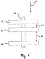
- Fig. 1 shows a rotor shaft 14 of a rotor of a turbomolecular pump according to the invention, shown here only partially, with two rotor sections designed as rotor disks 16 being connected to the rotor shaft 14 in a rotationally fixed manner.
- the respective rotor disk 16 has a plurality of rotor blades (not shown) which are arranged spaced apart in the circumferential direction.
- stator section designed as a stator disk 22, which is not connected to the rotor shaft 14, but statically to a housing of the turbo molecular pump, not shown.
- the stator disk 22 has a plurality of stator blades, likewise not shown, which are arranged spaced apart in the circumferential direction.
- first axial distance A1 between the upper rotor disk 16 and the stator disk 22, and there is a second axial distance A2 between the stator disk 22 and the lower rotor disk 16.
- the first axial distance A1 is smaller than the second axial distance A2.
- the axial distance A1 is approximately 0.4 times the second axial distance A2. According to the invention, this distance ratio must be less than 0.7.
- stator section is here arranged outside an axial center between the first rotor section, here the upper rotor disk 16, and the second rotor section, here the lower rotor disk 16.
- stator section is arranged closer to one of the adjacent rotor sections, namely closer to the upper rotor disk 16, than to the respective other rotor section, viewed in the axial direction, that is, along the rotor shaft 14.
- a pumping direction P describes a desired direction of movement of the gas molecules to be conveyed during a pumping process.
- the intermediate space immediately following the upper rotor disk 16 in the pumping direction P, which is assigned to the first axial distance A1 is smaller than the second intermediate space in the pumping direction, which immediately follows the stator disk 22 and the second axial distance A2 is assigned. It may be desirable to make the first axial distance A1 as small as possible in order to further improve the pumping capacity of the turbo molecular pump.
- rotor blades 18 and stator blades 24 are shown in simplified form, namely as a simplified developed view in the radial direction, ie in the direction of the rotor shaft 14 shown here only as a dashed line is arranged in front of a stator disk including the stator blades 24, also not shown in detail.
- the rotor blades 18 move in at high speed during pumping Fig. 2 to the right (direction of rotation) while the stator blades 24 are fixed, ie not moving.
- the rotor blades 18 and the stator blades 24 are arranged obliquely at a respective angle of attack of 45 °, the stator blades 24 being oriented obliquely opposite to the rotor blades 18.
- the angle of attack is measured here in each case starting from a plane running perpendicular to the rotor shaft 14.
- a molecule to be conveyed which gets into the axial area of the rotor blades 18, is to a certain extent captured by the obliquely downwardly directed surface of a rotor blade 18 moving rapidly to the right, the molecule being adsorbed on the surface. The molecule then desorbs from the surface, moving away from the rotor blade. The molecule adopts a preferred direction which is perpendicular to the surface from which the molecule was previously desorbed. In Fig.
- stator blades 24 are also aligned perpendicular to the obliquely downwardly directed surfaces of the rotor blades 18, so that a molecule which moves in the preferred direction can pass parallel to the stator blades 24 and thus almost unhindered through the axially following stator disk 22, with only the - relatively small - thickness of the stator blades 24 opposing this movement.
- the axial distance between the stator disk and the rotor disk following in the pumping direction has less of an influence on the pumping power. This is because here the molecule to be conveyed can be actively captured by the rotor disk, essentially regardless of its direction of movement, and thus transported further.
- the pumping performance of the turbo molecular pump is therefore improved by the invention, in particular in the molecular working range.
Landscapes
- Engineering & Computer Science (AREA)
- Mechanical Engineering (AREA)
- General Engineering & Computer Science (AREA)
- Non-Positive Displacement Air Blowers (AREA)
Description
- Die vorliegende Erfindung betrifft eine Vakuumpumpe, insbesondere Turbomolekularpumpe, mit wenigstens einem Rotor, der eine Rotorwelle und mehrere an der Rotorwelle angeordnete, axial längs der Rotorwelle beabstandete Rotorabschnitte aufweist, welche jeweils eine Mehrzahl von in Umfangsrichtung verteilt angeordneten Rotorschaufeln umfassen, und wenigstens einem dem Rotor zugeordneten Stator, der mehrere Statorabschnitte mit jeweils einer Mehrzahl von in Umfangsrichtung verteilt angeordneten Statorschaufeln aufweist, wobei ein jeweiliger Statorabschnitt in axialer Richtung zwischen einem ersten und einem zweiten Rotorabschnitt und zu diesen beiden Rotorabschnitten jeweils benachbart angeordnet ist, und wobei zwischen dem ersten Rotorabschnitt und einem jeweiligen Statorabschnitt ein erster axialer Abstand vorgesehen ist und zwischen dem jeweiligen Statorabschnitt und dem zweiten Rotorabschnitt ein zweiter axialer Abstand vorgesehen ist.
- Typischerweise sind eine Vielzahl von Rotorabschnitten und eine Vielzahl von Statorabschnitten vorgesehen, die in axialer Richtung abwechselnd angeordnet sind, wobei ein jeweiliger Statorabschnitt sich mittig zwischen zwei jeweils benachbarten Rotorabschnitten befindet. Die Rotorabschnitte können jeweils entweder einstückig mit der Rotorwelle ausgebildet oder in Form einer separat hergestellten und drehfest mit der Rotorwelle verbundenen Rotorscheibe vorgesehen sein.
- In der
JP 2000 257586 A - Bei einer aus der
EP 2 757 266 A1 bekannten Vakuumpumpe der eingangs genannten Art sind die Statorabschnitte über Distanzringe voneinander getrennt und jeweils zwischen zwei Rotorabschnitten angeordnet, von denen sie einen zumindest im Wesentlichen gleichen Abstand aufweisen. - Es ist eine Aufgabe der Erfindung, die Leistung einer derartigen Vakuumpumpe zu verbessern.
- Die Aufgabe wird durch eine Vakuumpumpe gemäß Anspruch 1 gelöst, und insbesondere dadurch, dass der zweite axiale Abstand von dem ersten axialen Abstand verschieden ist, wobei der erste Rotorabschnitt in Pumprichtung vor einem jeweiligen Statorabschnitt angeordnet ist und der zweite Rotorabschnitt in Pumprichtung nach dem jeweiligen Rotorabschnitt angeordnet ist, der erste axiale Abstand kleiner ist als der zweite Abstand und weniger als das 0,7-fache des zweiten axialen Abstands beträgt, und die beiden verschiedenen Abstände eines jeweiligen Statorabschnitts zu den beiden benachbarten Rotorabschnitten durch entsprechende Distanzringe zwischen den einzelnen Statorabschnitten definiert sind.
- Durch die Erfindung lässt sich die Anordnung der Rotor- und Statorabschnitte an die Bewegung der zu fördernden Moleküle anpassen, sodass die Pumpwirkung verbessert wird. Die Wirkungsweise der Erfindung wird nachstehend insbesondere anhand von
Fig. 2 näher erläutert. - Außerdem erlaubt die Erfindung, dass eine bestehende Konstruktion einer Vakuumpumpe dadurch verbessert werden kann, dass lediglich die Lage der Statorabschnitte relativ zu den Rotorabschnitten verändert wird. Dies kann z.B. durch veränderte Distanzringe zwischen einzelnen Statorabschnitten in besonders einfacher Weise realisiert werden. Die Erfindung verbessert also die Leistung einer Vakuumpumpe unter Einsatz besonders einfacher Mittel, ohne dass die Gesamtkonstruktion der Vakuumpumpe verändert werden muss.
- Ein jeweiliger Statorabschnitt ist zwischen zwei ihm benachbarten Rotorabschnitten angeordnet. Mit anderen Worten sind ein jeweiliger Statorabschnitt und jeder der beiden ihm benachbarten Rotorabschnitte in der jeweiligen axialen Richtung unmittelbar aufeinanderfolgend angeordnet. Zwischen einem jeweiligen Statorabschnitt und einem jeweiligen benachbarten Rotorabschnitt sind keine weiteren Stator- oder Rotorabschnitte angeordnet. Der jeweilige Statorabschnitt weist in beiden axialen Richtungen jeweils einen benachbarten Rotorabschnitt auf.
- Im Stand der Technik wird davon ausgegangen, dass eine optimale Leistung der Vakuumpumpe erzielt wird, wenn der Statorabschnitt genau in der Mitte zwischen zwei benachbarten Rotorabschnitten angeordnet ist. Erfindungsgemäß wurde jedoch erkannt, dass der erste axiale Abstand und der zweite axiale Abstand einen unterschiedlichen Einfluss auf die Pumpwirkung haben können, sodass sich die Pumpwirkung durch unterschiedliche Wahl der beiden Abstände vorteilhaft beeinflussen lässt.
- Der erste Rotorabschnitt ist dabei in Pumprichtung vor einem jeweiligen Statorabschnitt angeordnet, während der zweite Rotorabschnitt in Pumprichtung nach dem Statorabschnitt angeordnet ist. Dabei ist der erste axiale Abstand kleiner als der zweite axiale Abstand. Mit anderen Worten ist also der in Pumprichtung erste axiale Abstand kleiner als der in Pumprichtung zweite axiale Abstand. Dabei kann der erste axiale Abstand möglichst klein ausgeführt sein. Dabei wird zwischen einem jeweiligen Statorabschnitt und einem benachbarten Rotorabschnitt ein gewisser Mindestabstand größer Null eingehalten. Obwohl durch Verkleinern des ersten axialen Abstands der zweite axiale Abstand relativ groß werden kann, hat sich gezeigt, dass der zweite axiale Abstand keinen so starken Einfluss auf die Pumpleistung ausübt, sodass insgesamt die Pumpleistung verbessert wird, wenn der erste axiale Abstand verkleinert wird.
- Erfindungsgemäß beträgt der erste axiale Abstand weniger als das 0,7-fache des zweiten axialen Abstands. Bei dieser Ausgestaltung hat sich eine besonders gute Pumpleistung ergeben. Noch bessere Pumpleistungen können sich ergeben, wenn gemäß einer Ausführungsform der erste axiale Abstand kleiner als die oder gleich der Hälfte des zweiten axialen Abstands ist.
- Bei einer weiteren Ausführungsform ist die Rotorwelle einlassseitig, insbesondere in einem Hochvakuumbereich, durch ein schmierungsfreies Lager, insbesondere ein Magnetlager, gelagert. Dadurch lässt sich die einlassseitige Lagerung nicht nur wartungsfrei ausführen, sondern eine Kontamination des Vakuums durch die Lagerung wird außerdem aufgrund fehlender Schmierstoffe verhindert.
- Die Rotorwelle kann alternativ oder zusätzlich auslassseitig, insbesondere in einem Mittel- oder Niedrigvakuumbereich, durch ein geschmiertes Lager, insbesondere ein Wälzlager wie z.B. ein Kugellager, gelagert sein. Dies erlaubt eine kostengünstige und mit relativ wenig Spiel behaftete Lagerung, während die Kontaminationsproblematik an der Auslassseite entfällt.
- Bei einer Ausführungsform ist zumindest ein Rotorabschnitt mit der Rotorwelle einstückig ausgebildet ist. Insbesondere sind dabei alle Rotorabschnitte mit der Rotorwelle einstückig ausgebildet. Ein derart ausgestalteter Rotor wird auch als Vollrotor bezeichnet. Im Gegensatz dazu kann zumindest ein Rotorabschnitt durch eine separat von der Rotorwelle hergestellte und an der Rotorwelle befestigte Rotorscheibe gebildet sein. Insbesondere können alle Rotorabschnitte durch separat hergestellte Rotorscheiben gebildet sein. Man spricht hierbei auch von einem Scheibenrotor.
- Bei einer weiteren Ausführungsform ist zumindest ein Statorabschnitt als aus Blech hergestellte Statorscheibe ausgeführt. Dadurch wird die Herstellung der Statorscheibe und damit auch jene der Vakuumpumpe technisch vereinfacht und kostengünstiger. Insbesondere ist die Statorscheibe aus Blech gestanzt, was den Herstellungsvorgang weiter vereinfacht.
- Die Rotorschaufeln und die Statorschaufeln können jeweils zu einer zumindest im Wesentlichen senkrecht zu einer Rotationsachse verlaufenden Ebene schräg gestellt sein, wobei die Rotorschaufeln einen Anstellwinkel und die Statorschaufeln einen Anstellwinkel aufweisen und die Summe aus dem Anstellwinkel der Statorschaufeln und dem Anstellwinkel der Rotorschaufeln zumindest im Wesentlichen 90° beträgt. Mit anderen Worten kann eine jeweilige Statorschaufel, insbesondere mit einem radial äußeren Bereich, zumindest im Wesentlichen senkrecht zu einer jeweiligen Rotorschaufel, insbesondere zu deren radial äußerem Bereich, ausgerichtet sein. Die zu fördernden Moleküle entfernen sich vornehmlich senkrecht von einer jeweiligen Schaufelfläche des Rotors in Richtung des Statorabschnitts, wie unten anhand von
Fig. 2 näher erläutert. Wenn also die Statorschaufeln parallel zu dieser Bewegungsrichtung der Moleküle ausgerichtet sind, setzen sie den Molekülen einen minimalen Widerstand entgegen und die Pumpleistung wird optimiert. - Bei einer Ausführungsform der Erfindung beträgt der Anstellwinkel der Rotorschaufeln zumindest im Wesentlichen 45°, wodurch die Leistung der Pumpe weiter verbessert werden kann.
- Weitere Ausführungsformen der Erfindung sind in den abhängigen Ansprüchen, der Beschreibung und den Figuren angegeben.
- Die Erfindung wird nachfolgend lediglich beispielhaft unter Bezugnahme auf die schematische Zeichnung erläutert.
- Fig. 1
- zeigt eine erfindungsgemäße Anordnung zweier Rotorscheiben mit einer dazwischenliegenden Statorscheibe, und
- Fig. 2
- zeigt Rotor- und Statorschaufeln zur Veranschaulichung der Wirkungsweise der Erfindung.
- Eine beispielhafte, als Turbomolekularpumpe ausgebildete Vakuumpumpe (nicht gezeigt), welche durch die Erfindung und auch durch zumindest eine der hier offenbarten Ausführungsformen weitergebildet werden kann, umfasst einen von einem Einlassflansch umgebenen Einlass sowie mehrere Pumpstufen zur Förderung des an dem Einlass anstehenden Gases zu einem Auslass. Die Turbomolekularpumpe kann eine seitliche Anzapfung aufweisen. Die Turbomolekularpumpe umfasst einen Stator mit einem statischen Gehäuse und einen in dem Gehäuse angeordneten Rotor mit einer um eine Rotationsachse drehbar gelagerten Rotorwelle.
- Die Turbomolekularpumpe umfasst mehrere pumpwirksam miteinander in Serie geschaltete turbomolekulare Pumpstufen mit mehreren mit der Rotorwelle verbundenen, als turbomolekulare Rotorscheiben ausgebildeten Rotorabschnitten und mit mehreren in axialer Richtung zwischen den Rotorscheiben angeordneten und in dem Gehäuse festgelegten, als turbomolekulare Statorscheiben ausgebildeten Statorabschnitten, die durch Distanzringe in einem gewünschten axialen Abstand zueinander gehalten sind. Die Rotorscheiben und Statorscheiben stellen in einem Schöpfbereich eine in Pumprichtung gerichtete axiale Pumpwirkung bereit.
- Die Turbomolekularpumpe umfasst zudem drei in radialer Richtung ineinander angeordnete und pumpwirksam miteinander in Serie geschaltete Holweck-Pumpstufen. Der rotorseitige Teil der Holweck-Pumpstufen umfasst zwei an der Rotorwelle befestigte und von dieser getragene zylindermantelförmige Holweck-Rotorhülsen, die koaxial zu der Rotationsachse orientiert und ineinander geschachtelt sind. Ferner sind zwei zylindermantelförmige Holweck-Statorhülsen vorgesehen, die ebenfalls koaxial zu der Rotationsachse orientiert und ineinander geschachtelt sind. Die pumpaktiven Oberflächen der Holweck-Pumpstufen sind jeweils durch die einander unter Ausbildung eines engen radialen Holweck-Spalts gegenüberliegenden radialen Mantelflächen, nämlich jeweils einer Holweck-Rotorhülse und einer Holweck-Statorhülse, gebildet. Dabei ist jeweils eine der pumpaktiven Oberflächen glatt ausgebildet, im vorliegenden Fall beispielsweise die der Holweck-Rotorhülse, wobei die gegenüberliegende pumpaktive Oberfläche der jeweiligen Holweck-Statorhülse eine Strukturierung mit schraubenlinienförmig um die Rotationsachse herum in axialer Richtung verlaufenden Nuten aufweist, in denen durch die Rotation des Rotors das Gas vorangetrieben und dadurch gepumpt wird.
- Die drehbare Lagerung der Rotorwelle wird durch ein Wälzlager im Bereich des Auslasses und ein Permanentmagnetlager im Bereich des Einlasses bewirkt.
- Das Permanentmagnetlager umfasst eine rotorseitige Lagerhälfte und eine statorseitige Lagerhälfte, die jeweils einen Ringstapel aus mehreren in axialer Richtung aufeinander gestapelten permanentmagnetischen Ringen umfassen, wobei die Magnetringe unter Ausbildung eines radialen Lagerspalts einander gegenüberliegen.
- Innerhalb des Permanentmagnetlagers ist ein Not- oder Fanglager vorgesehen, das als ungeschmiertes Wälzlager ausgebildet ist und im normalen Betrieb der Vakuumpumpe ohne Berührung leer läuft und erst bei einer übermäßigen radialen Auslenkung des Rotors gegenüber dem Stator in Eingriff gelangt, um einen radialen Anschlag für den Rotor zu bilden, der eine Kollision der rotorseitigen Strukturen mit den statorseitigen Strukturen verhindert.
- Im Bereich des Wälzlagers ist an der Rotorwelle eine konische Spritzmutter mit einem zu dem Wälzlager hin zunehmenden Außendurchmesser vorgesehen, die mit einem Abstreifer eines mehrere mit einem Betriebsmittel, wie z.B. einem Schmiermittel, getränkte saugfähige Scheiben umfassenden Betriebsmittelspeichers in gleitendem Kontakt steht. Im Betrieb wird das Betriebsmittel durch kapillare Wirkung von dem Betriebsmittelspeicher über den Abstreifer auf die rotierende Spritzmutter übertragen und infolge der Zentrifugalkraft entlang der Spritzmutter in Richtung des größer werdenden Außendurchmessers der Spritzmutter zu dem Wälzlager hin gefördert, wo es z.B. eine schmierende Funktion erfüllt.
- Die Turbomolekularpumpe umfasst einen Antriebsmotor zum drehenden Antreiben des Rotors, dessen Läufer durch die Rotorwelle gebildet ist. Eine Steuereinheit steuert den Antriebsmotor an.
-
Fig. 1 zeigt eine Rotorwelle 14 eines hier nur teilweise dargestellten Rotors einer erfindungsgemäßen Turbomolekularpumpe, wobei mit der Rotorwelle 14 zwei als Rotorscheiben 16 ausgebildete Rotorabschnitte drehfest verbunden sind. Eine jeweilige Rotorscheibe 16 weist eine Mehrzahl von in Umfangsrichtung beabstandet angeordneten, nicht dargestellten Rotorschaufeln auf. - Zwischen den Rotorscheiben 16 ist ein als Statorscheibe 22 ausgebildeter Statorabschnitt angeordnet, welcher nicht mit der Rotorwelle 14, sondern statisch mit einem nicht dargestellten Gehäuse der Turbomolekularpumpe verbunden ist. Die Statorscheibe 22 weist eine Mehrzahl von in Umfangsrichtung beabstandet angeordneten, ebenfalls nicht dargestellten Statorschaufeln auf.
- Zwischen der oberen Rotorscheibe 16 und der Statorscheibe 22 besteht ein erster axialer Abstand A1 und zwischen der Statorscheibe 22 und der unteren Rotorscheibe 16 besteht ein zweiter axialer Abstand A2. Der erste axiale Abstand A1 ist kleiner als der zweite axiale Abstand A2. Hierbei beträgt der axiale Abstand A1 etwa das 0,4-fache des zweiten axialen Abstands A2. Dieses Abstandsverhältnis muss erfindungsgemäß kleiner als 0,7 sein.
- Der Statorabschnitt ist hier also, mit anderen Worten, außerhalb einer axialen Mitte zwischen dem ersten Rotorabschnitt, hier der oberen Rotorscheibe 16, und dem zweiten Rotorabschnitt, hier der unteren Rotorscheibe 16, angeordnet. Wiederum mit anderen Worten ist der Statorabschnitt in axialer Richtung, also längs der Rotorwelle 14, betrachtet näher an einem der benachbarten Rotorabschnitte, nämlich näher an der oberen Rotorscheibe 16, als an dem jeweils anderen Rotorabschnitt angeordnet.
- Eine Pumprichtung P beschreibt eine erwünschte Bewegungsrichtung von zu fördernden Gasmolekülen während eines Pumpvorgangs. Der in Pumprichtung P unmittelbar auf die obere Rotorscheibe 16 folgende Zwischenraum, welcher dem ersten axialen Abstand A1 zugeordnet ist, ist kleiner als der in Pumprichtung zweite Zwischenraum, welcher unmittelbar auf die Statorscheibe 22 folgt und dem zweiten axialen Abstand A2 zugeordnet ist. Dabei kann es wünschenswert sein, den ersten axialen Abstand A1 möglichst gering auszuführen, um die Pumpleistung der Turbomolekularpumpe weiter zu verbessern.
- Die Wirkungsweise der Erfindung soll nun anhand von
Fig. 2 und eines vereinfachten physikalischen Modells genauer veranschaulicht werden. - In
Fig. 2 sind dazu Rotorschaufeln 18 und Statorschaufeln 24 vereinfacht dargestellt, und zwar als vereinfachte abgewickelte Ansicht in radialer Richtung, d.h. in Richtung auf die hier nur als gestrichelte Linie dargestellte Rotorwelle 14. Die Rotorschaufeln 18 sind Teil einer nicht näher dargestellten Rotorscheibe, welche in Pumprichtung P unmittelbar vor einer die Statorschaufeln 24 umfassenden, ebenfalls nicht näher dargestellten Statorscheibe angeordnet ist. - Die Rotorschaufeln 18 bewegen sich während des Pumpvorgangs mit hoher Geschwindigkeit in
Fig. 2 nach rechts (Rotationsrichtung), während die Statorschaufeln 24 fest sind, d.h. sich nicht bewegen. Die Rotorschaufeln 18 sowie die Statorschaufeln 24 sind schräg unter einem jeweiligen Anstellwinkel von 45°angeordnet, wobei die Statorschaufeln 24 zu den Rotorschaufeln 18 entgegengesetzt schräg ausgerichtet sind. Der Anstellwinkel wird hierbei jeweils ausgehend von einer senkrecht zur Rotorwelle 14 verlaufenden Ebene gemessen. - Ein zu förderndes Molekül, welches in den axialen Bereich der Rotorschaufeln 18 gerät, wird durch die schräg nach unten gerichtete Fläche einer sich schnell nach rechts bewegenden Rotorschaufel 18 gewissermaßen eingefangen, wobei das Molekül an der Fläche adsorbiert. Anschließend desorbiert das Molekül von der Fläche, wobei es sich von der Rotorschaufel entfernt. Dabei nimmt das Molekül eine Vorzugsrichtung an, welche senkrecht zu der Fläche steht, von welcher das Molekül zuvor desorbiert ist. In
Fig. 2 sind auch die Statorschaufeln 24 senkrecht zu den schräg nach unten gerichteten Flächen der Rotorschaufeln 18 ausgerichtet, so dass ein Molekül, welches sich in der Vorzugsrichtung bewegt, parallel zu den Statorschaufeln 24 und somit nahezu ungehindert durch die axial nachfolgende Statorscheibe 22 hindurchtreten kann, wobei lediglich die - relativ geringe - Dicke der Statorschaufeln 24 dieser Bewegung entgegensteht. - Je weiter allerdings die Strecke ist, welche das Molekül nach der Desorption von der Rotorschaufel 18 beim Eintreten in den axialen Bereich der nachfolgenden Statorscheibe 22 bereits zurückgelegt hat, desto wahrscheinlicher weicht seine Bewegungsrichtung von der oben erwähnten Vorzugsrichtung ab. Dies wird zum Beispiel durch Stöße mit der Gehäusewand, der Rotorwelle oder anderen Molekülen begründet und kann auch als "Verwischen" bezeichnet werden. Erfindungsgemäß wurde erkannt, dass die Durchtrittswahrscheinlichkeit für ein jeweiliges zu förderndes Molekül steigt, wenn die Statorscheibe möglichst nahe an der Rotorscheibe angeordnet ist und dadurch mit hoher Wahrscheinlichkeit das Molekül nicht bereits eine von der Vorzugsrichtung abweichende Bewegungsrichtung aufweist, wenn es die Statorscheibe erreicht. Dagegen nimmt der axiale Abstand der Statorscheibe zur in Pumprichtung nachfolgenden Rotorscheibe weniger Einfluss auf die Pumpleistung. Denn hier kann das zu fördernde Molekül im Wesentlichen unabhängig von seiner Bewegungsrichtung durch die Rotorscheibe aktiv eingefangen und dadurch weitertransportiert werden. Die Pumpleistung der Turbomolekularpumpe wird also insbesondere im molekularen Arbeitsbereich durch die Erfindung verbessert.
-
- 14
- Rotorwelle
- 16
- Rotorscheibe
- 18
- Rotorschaufel
- 22
- Statorscheibe
- 24
- Statorschaufel
- P
- Pumprichtung
Claims (9)
- Vakuumpumpe, insbesondere Turbomolekularpumpe, mitwenigstens einem Rotor, der eine Rotorwelle (14) und mehrere an der Rotorwelle (14) angeordnete, axial längs der Rotorwelle (14) beabstandete Rotorabschnitte (16) aufweist, welche jeweils eine Mehrzahl von in Umfangsrichtung verteilt angeordneten Rotorschaufeln (18) umfassen, undwenigstens einem dem Rotor zugeordneten Stator, der mehrere Statorabschnitte (22) mit jeweils einer Mehrzahl von in Umfangsrichtung verteilt angeordneten Statorschaufeln (24) aufweist,wobei ein jeweiliger Statorabschnitt (22) in axialer Richtung zwischen einem ersten und einem zweiten Rotorabschnitt (16) und zu diesen beiden Rotorabschnitten (16) jeweils benachbart angeordnet ist,wobei zwischen dem ersten Rotorabschnitt (16) und einem jeweiligen Statorabschnitt (22) ein erster axialer Abstand (A1) vorgesehen ist und zwischen dem jeweiligen Statorabschnitt (22) und dem zweiten Rotorabschnitt (16) ein zweiter axialer Abstand (A2) vorgesehen ist,wobei der zweite axiale Abstand (A2) von dem ersten axialen Abstand (A1) verschieden ist,wobei der erste Rotorabschnitt (16) in Pumprichtung (P) vor einem jeweiligen Statorabschnitt (22) angeordnet ist und der zweite Rotorabschnitt (16) in Pumprichtung (P) nach dem jeweiligen Statorabschnitt (22) angeordnet ist, wobei der erste axiale Abstand (A1) kleiner ist als der zweite axiale Abstand (A2), dadurch gekennzeichnet, dass der erste axiale Abstand (A1) weniger als das 0,7-fache des zweiten axialen Abstands (A2) beträgt,und dass die beiden verschiedenen Abstände (A1, A2) eines jeweiligen Statorabschnitts (22) zu den beiden benachbarten Rotorabschnitten (16) durch entsprechende Distanzringe zwischen den einzelnen Statorabschnitten (22) definiert sind.
- Vakuumpumpe nach Anspruch 1,
dadurch gekennzeichnet, dass der erste axiale Abstand (A1) kleiner ist als die Hälfte des zweiten axialen Abstands (A2). - Vakuumpumpe nach Anspruch 1 oder 2,
dadurch gekennzeichnet, dass die Rotorwelle (14) einlassseitig durch ein schmierungsfreies Lager, insbesondere ein Magnetlager, gelagert ist. - Vakuumpumpe nach einem der vorhergehenden Ansprüche,
dadurch gekennzeichnet, dass die Rotorwelle (14) auslassseitig durch ein geschmiertes Lager, insbesondere ein Wälzlager, gelagert ist. - Vakuumpumpe nach einem der vorhergehenden Ansprüche,
dadurch gekennzeichnet, dass zumindest ein Rotorabschnitt (16) mit der Rotorwelle (14) einstückig ausgebildet ist. - Vakuumpumpe nach einem der vorhergehenden Ansprüche,
dadurch gekennzeichnet, dass zumindest ein Statorabschnitt (22) als aus Blech hergestellte Statorscheibe ausgeführt ist. - Vakuumpumpe nach Anspruch 6,
dadurch gekennzeichnet, dass die Statorscheibe aus Blech gestanzt ist. - Vakuumpumpe nach einem der vorhergehenden Ansprüche,
dadurch gekennzeichnet, dass die Rotorschaufeln (18) und die Statorschaufeln (24) jeweils zu einer zumindest im Wesentlichen senkrecht zu einer Rotationsachse (R) verlaufenden Ebene schräg gestellt sind, wobei die Rotorschaufeln (18) einen Anstellwinkel und die Statorschaufeln (24) einen Anstellwinkel aufweisen und die Summe aus dem Anstellwinkel der Statorschaufeln (24) und dem Anstellwinkel der Rotorschaufeln (18) zumindest im Wesentlichen 90° beträgt. - Vakuumpumpe nach Anspruch 8,
dadurch gekennzeichnet, dass der Anstellwinkel der Rotorschaufeln (18) zumindest im Wesentlichen 45° beträgt.
Priority Applications (1)
| Application Number | Priority Date | Filing Date | Title |
|---|---|---|---|
| EP15181767.3A EP3133290B1 (de) | 2015-08-20 | 2015-08-20 | Vakuumpumpe |
Applications Claiming Priority (1)
| Application Number | Priority Date | Filing Date | Title |
|---|---|---|---|
| EP15181767.3A EP3133290B1 (de) | 2015-08-20 | 2015-08-20 | Vakuumpumpe |
Publications (2)
| Publication Number | Publication Date |
|---|---|
| EP3133290A1 EP3133290A1 (de) | 2017-02-22 |
| EP3133290B1 true EP3133290B1 (de) | 2021-06-09 |
Family
ID=53887009
Family Applications (1)
| Application Number | Title | Priority Date | Filing Date |
|---|---|---|---|
| EP15181767.3A Active EP3133290B1 (de) | 2015-08-20 | 2015-08-20 | Vakuumpumpe |
Country Status (1)
| Country | Link |
|---|---|
| EP (1) | EP3133290B1 (de) |
Families Citing this family (2)
| Publication number | Priority date | Publication date | Assignee | Title |
|---|---|---|---|---|
| CN113187743A (zh) * | 2021-04-08 | 2021-07-30 | 日扬科技股份有限公司 | 长效运转的转子结构 |
| CN116624392B (zh) * | 2023-04-24 | 2024-05-17 | 北京通嘉宏瑞科技有限公司 | 定子、真空泵及真空泵的装配方法 |
Family Cites Families (5)
| Publication number | Priority date | Publication date | Assignee | Title |
|---|---|---|---|---|
| DE29516599U1 (de) * | 1995-10-20 | 1995-12-07 | Leybold AG, 50968 Köln | Reibungsvakuumpumpe mit Zwischeneinlaß |
| DE19804768B4 (de) * | 1998-02-06 | 2006-08-24 | Pfeiffer Vacuum Gmbh | Rotorlagerung für eine Gasreibungspumpe |
| JP2000257586A (ja) * | 1999-03-08 | 2000-09-19 | Koyo Seiko Co Ltd | ターボ分子ポンプ |
| JP2003003987A (ja) * | 2001-06-22 | 2003-01-08 | Osaka Vacuum Ltd | 分子ポンプ |
| EP2757266B1 (de) * | 2013-01-22 | 2016-03-16 | Agilent Technologies, Inc. | Rotationsvakuumpumpe |
-
2015
- 2015-08-20 EP EP15181767.3A patent/EP3133290B1/de active Active
Non-Patent Citations (1)
| Title |
|---|
| None * |
Also Published As
| Publication number | Publication date |
|---|---|
| EP3133290A1 (de) | 2017-02-22 |
Similar Documents
| Publication | Publication Date | Title |
|---|---|---|
| EP2933497B1 (de) | Vakuumpumpe | |
| EP3657021B1 (de) | Vakuumpumpe | |
| EP2458222B1 (de) | Turbomolekularpumpe | |
| DE102013214662A1 (de) | Vakuumpumpe | |
| DE4209126C2 (de) | Peripheralpumpe | |
| EP3133290B1 (de) | Vakuumpumpe | |
| EP3608545B1 (de) | Vakuumpumpe | |
| EP3693610B1 (de) | Molekularvakuumpumpe | |
| EP3091235B1 (de) | Rotorscheibe | |
| EP3845764B1 (de) | Vakuumpumpe und vakuumpumpensystem | |
| EP3093496B1 (de) | Rotor einer vakuumpumpe | |
| EP4194700B1 (de) | Vakuumpumpe mit einer holweck-pumpstufe mit veränderlicher holweck-geometrie | |
| DE102015104438A1 (de) | Vakuumsystem | |
| EP3135932B1 (de) | Vakuumpumpe und permanentmagnetlager | |
| EP3734078B1 (de) | Turbomolekularpumpe und verfahren zur herstellung einer statorscheibe für eine solche | |
| DE102014118083A1 (de) | Turbomolekularpumpe | |
| EP3032106B1 (de) | Vakuumpumpe | |
| EP3088746A1 (de) | Vakuumpumpe | |
| EP4227539B1 (de) | Vakuumpumpe | |
| EP3001039A2 (de) | Vakuumpumpe | |
| EP3767109B1 (de) | Vakuumsystem | |
| EP4273405B1 (de) | Vakuumpumpe mit einer holweck-pumpstufe mit veränderlicher holweck-geometrie | |
| EP3096020B1 (de) | Vakuumpumpe | |
| EP3051140B1 (de) | Statorscheibe für eine vakuumpumpe | |
| EP3135919B1 (de) | Vakuumpumpe |
Legal Events
| Date | Code | Title | Description |
|---|---|---|---|
| PUAI | Public reference made under article 153(3) epc to a published international application that has entered the european phase |
Free format text: ORIGINAL CODE: 0009012 |
|
| STAA | Information on the status of an ep patent application or granted ep patent |
Free format text: STATUS: THE APPLICATION HAS BEEN PUBLISHED |
|
| STAA | Information on the status of an ep patent application or granted ep patent |
Free format text: STATUS: REQUEST FOR EXAMINATION WAS MADE |
|
| AK | Designated contracting states |
Kind code of ref document: A1 Designated state(s): AL AT BE BG CH CY CZ DE DK EE ES FI FR GB GR HR HU IE IS IT LI LT LU LV MC MK MT NL NO PL PT RO RS SE SI SK SM TR |
|
| AX | Request for extension of the european patent |
Extension state: BA ME |
|
| 17P | Request for examination filed |
Effective date: 20170207 |
|
| RBV | Designated contracting states (corrected) |
Designated state(s): AL AT BE BG CH CY CZ DE DK EE ES FI FR GB GR HR HU IE IS IT LI LT LU LV MC MK MT NL NO PL PT RO RS SE SI SK SM TR |
|
| STAA | Information on the status of an ep patent application or granted ep patent |
Free format text: STATUS: EXAMINATION IS IN PROGRESS |
|
| 17Q | First examination report despatched |
Effective date: 20190116 |
|
| GRAP | Despatch of communication of intention to grant a patent |
Free format text: ORIGINAL CODE: EPIDOSNIGR1 |
|
| STAA | Information on the status of an ep patent application or granted ep patent |
Free format text: STATUS: GRANT OF PATENT IS INTENDED |
|
| INTG | Intention to grant announced |
Effective date: 20210303 |
|
| GRAS | Grant fee paid |
Free format text: ORIGINAL CODE: EPIDOSNIGR3 |
|
| GRAA | (expected) grant |
Free format text: ORIGINAL CODE: 0009210 |
|
| STAA | Information on the status of an ep patent application or granted ep patent |
Free format text: STATUS: THE PATENT HAS BEEN GRANTED |
|
| AK | Designated contracting states |
Kind code of ref document: B1 Designated state(s): AL AT BE BG CH CY CZ DE DK EE ES FI FR GB GR HR HU IE IS IT LI LT LU LV MC MK MT NL NO PL PT RO RS SE SI SK SM TR |
|
| REG | Reference to a national code |
Ref country code: GB Ref legal event code: FG4D Free format text: NOT ENGLISH |
|
| REG | Reference to a national code |
Ref country code: CH Ref legal event code: EP Ref country code: AT Ref legal event code: REF Ref document number: 1400733 Country of ref document: AT Kind code of ref document: T Effective date: 20210615 |
|
| REG | Reference to a national code |
Ref country code: DE Ref legal event code: R096 Ref document number: 502015014794 Country of ref document: DE |
|
| REG | Reference to a national code |
Ref country code: IE Ref legal event code: FG4D Free format text: LANGUAGE OF EP DOCUMENT: GERMAN |
|
| REG | Reference to a national code |
Ref country code: LT Ref legal event code: MG9D |
|
| PG25 | Lapsed in a contracting state [announced via postgrant information from national office to epo] |
Ref country code: FI Free format text: LAPSE BECAUSE OF FAILURE TO SUBMIT A TRANSLATION OF THE DESCRIPTION OR TO PAY THE FEE WITHIN THE PRESCRIBED TIME-LIMIT Effective date: 20210609 Ref country code: LT Free format text: LAPSE BECAUSE OF FAILURE TO SUBMIT A TRANSLATION OF THE DESCRIPTION OR TO PAY THE FEE WITHIN THE PRESCRIBED TIME-LIMIT Effective date: 20210609 Ref country code: BG Free format text: LAPSE BECAUSE OF FAILURE TO SUBMIT A TRANSLATION OF THE DESCRIPTION OR TO PAY THE FEE WITHIN THE PRESCRIBED TIME-LIMIT Effective date: 20210909 Ref country code: HR Free format text: LAPSE BECAUSE OF FAILURE TO SUBMIT A TRANSLATION OF THE DESCRIPTION OR TO PAY THE FEE WITHIN THE PRESCRIBED TIME-LIMIT Effective date: 20210609 |
|
| REG | Reference to a national code |
Ref country code: NL Ref legal event code: MP Effective date: 20210609 |
|
| PG25 | Lapsed in a contracting state [announced via postgrant information from national office to epo] |
Ref country code: LV Free format text: LAPSE BECAUSE OF FAILURE TO SUBMIT A TRANSLATION OF THE DESCRIPTION OR TO PAY THE FEE WITHIN THE PRESCRIBED TIME-LIMIT Effective date: 20210609 Ref country code: GR Free format text: LAPSE BECAUSE OF FAILURE TO SUBMIT A TRANSLATION OF THE DESCRIPTION OR TO PAY THE FEE WITHIN THE PRESCRIBED TIME-LIMIT Effective date: 20210910 Ref country code: NO Free format text: LAPSE BECAUSE OF FAILURE TO SUBMIT A TRANSLATION OF THE DESCRIPTION OR TO PAY THE FEE WITHIN THE PRESCRIBED TIME-LIMIT Effective date: 20210909 Ref country code: RS Free format text: LAPSE BECAUSE OF FAILURE TO SUBMIT A TRANSLATION OF THE DESCRIPTION OR TO PAY THE FEE WITHIN THE PRESCRIBED TIME-LIMIT Effective date: 20210609 Ref country code: SE Free format text: LAPSE BECAUSE OF FAILURE TO SUBMIT A TRANSLATION OF THE DESCRIPTION OR TO PAY THE FEE WITHIN THE PRESCRIBED TIME-LIMIT Effective date: 20210609 |
|
| PG25 | Lapsed in a contracting state [announced via postgrant information from national office to epo] |
Ref country code: ES Free format text: LAPSE BECAUSE OF FAILURE TO SUBMIT A TRANSLATION OF THE DESCRIPTION OR TO PAY THE FEE WITHIN THE PRESCRIBED TIME-LIMIT Effective date: 20210609 Ref country code: RO Free format text: LAPSE BECAUSE OF FAILURE TO SUBMIT A TRANSLATION OF THE DESCRIPTION OR TO PAY THE FEE WITHIN THE PRESCRIBED TIME-LIMIT Effective date: 20210609 Ref country code: NL Free format text: LAPSE BECAUSE OF FAILURE TO SUBMIT A TRANSLATION OF THE DESCRIPTION OR TO PAY THE FEE WITHIN THE PRESCRIBED TIME-LIMIT Effective date: 20210609 Ref country code: PT Free format text: LAPSE BECAUSE OF FAILURE TO SUBMIT A TRANSLATION OF THE DESCRIPTION OR TO PAY THE FEE WITHIN THE PRESCRIBED TIME-LIMIT Effective date: 20211011 Ref country code: EE Free format text: LAPSE BECAUSE OF FAILURE TO SUBMIT A TRANSLATION OF THE DESCRIPTION OR TO PAY THE FEE WITHIN THE PRESCRIBED TIME-LIMIT Effective date: 20210609 Ref country code: SM Free format text: LAPSE BECAUSE OF FAILURE TO SUBMIT A TRANSLATION OF THE DESCRIPTION OR TO PAY THE FEE WITHIN THE PRESCRIBED TIME-LIMIT Effective date: 20210609 Ref country code: SK Free format text: LAPSE BECAUSE OF FAILURE TO SUBMIT A TRANSLATION OF THE DESCRIPTION OR TO PAY THE FEE WITHIN THE PRESCRIBED TIME-LIMIT Effective date: 20210609 |
|
| PG25 | Lapsed in a contracting state [announced via postgrant information from national office to epo] |
Ref country code: PL Free format text: LAPSE BECAUSE OF FAILURE TO SUBMIT A TRANSLATION OF THE DESCRIPTION OR TO PAY THE FEE WITHIN THE PRESCRIBED TIME-LIMIT Effective date: 20210609 |
|
| REG | Reference to a national code |
Ref country code: DE Ref legal event code: R097 Ref document number: 502015014794 Country of ref document: DE |
|
| REG | Reference to a national code |
Ref country code: CH Ref legal event code: PL |
|
| PG25 | Lapsed in a contracting state [announced via postgrant information from national office to epo] |
Ref country code: MC Free format text: LAPSE BECAUSE OF FAILURE TO SUBMIT A TRANSLATION OF THE DESCRIPTION OR TO PAY THE FEE WITHIN THE PRESCRIBED TIME-LIMIT Effective date: 20210609 |
|
| PLBE | No opposition filed within time limit |
Free format text: ORIGINAL CODE: 0009261 |
|
| STAA | Information on the status of an ep patent application or granted ep patent |
Free format text: STATUS: NO OPPOSITION FILED WITHIN TIME LIMIT |
|
| REG | Reference to a national code |
Ref country code: BE Ref legal event code: MM Effective date: 20210831 |
|
| PG25 | Lapsed in a contracting state [announced via postgrant information from national office to epo] |
Ref country code: LI Free format text: LAPSE BECAUSE OF NON-PAYMENT OF DUE FEES Effective date: 20210831 Ref country code: DK Free format text: LAPSE BECAUSE OF FAILURE TO SUBMIT A TRANSLATION OF THE DESCRIPTION OR TO PAY THE FEE WITHIN THE PRESCRIBED TIME-LIMIT Effective date: 20210609 Ref country code: CH Free format text: LAPSE BECAUSE OF NON-PAYMENT OF DUE FEES Effective date: 20210831 |
|
| 26N | No opposition filed |
Effective date: 20220310 |
|
| PG25 | Lapsed in a contracting state [announced via postgrant information from national office to epo] |
Ref country code: LU Free format text: LAPSE BECAUSE OF NON-PAYMENT OF DUE FEES Effective date: 20210820 Ref country code: AL Free format text: LAPSE BECAUSE OF FAILURE TO SUBMIT A TRANSLATION OF THE DESCRIPTION OR TO PAY THE FEE WITHIN THE PRESCRIBED TIME-LIMIT Effective date: 20210609 |
|
| PG25 | Lapsed in a contracting state [announced via postgrant information from national office to epo] |
Ref country code: IE Free format text: LAPSE BECAUSE OF NON-PAYMENT OF DUE FEES Effective date: 20210820 Ref country code: FR Free format text: LAPSE BECAUSE OF NON-PAYMENT OF DUE FEES Effective date: 20210831 Ref country code: BE Free format text: LAPSE BECAUSE OF NON-PAYMENT OF DUE FEES Effective date: 20210831 |
|
| REG | Reference to a national code |
Ref country code: AT Ref legal event code: MM01 Ref document number: 1400733 Country of ref document: AT Kind code of ref document: T Effective date: 20210820 |
|
| PG25 | Lapsed in a contracting state [announced via postgrant information from national office to epo] |
Ref country code: AT Free format text: LAPSE BECAUSE OF NON-PAYMENT OF DUE FEES Effective date: 20210820 |
|
| PG25 | Lapsed in a contracting state [announced via postgrant information from national office to epo] |
Ref country code: HU Free format text: LAPSE BECAUSE OF FAILURE TO SUBMIT A TRANSLATION OF THE DESCRIPTION OR TO PAY THE FEE WITHIN THE PRESCRIBED TIME-LIMIT; INVALID AB INITIO Effective date: 20150820 |
|
| PG25 | Lapsed in a contracting state [announced via postgrant information from national office to epo] |
Ref country code: CY Free format text: LAPSE BECAUSE OF FAILURE TO SUBMIT A TRANSLATION OF THE DESCRIPTION OR TO PAY THE FEE WITHIN THE PRESCRIBED TIME-LIMIT Effective date: 20210609 |
|
| PG25 | Lapsed in a contracting state [announced via postgrant information from national office to epo] |
Ref country code: MK Free format text: LAPSE BECAUSE OF FAILURE TO SUBMIT A TRANSLATION OF THE DESCRIPTION OR TO PAY THE FEE WITHIN THE PRESCRIBED TIME-LIMIT Effective date: 20210609 |
|
| PG25 | Lapsed in a contracting state [announced via postgrant information from national office to epo] |
Ref country code: MT Free format text: LAPSE BECAUSE OF FAILURE TO SUBMIT A TRANSLATION OF THE DESCRIPTION OR TO PAY THE FEE WITHIN THE PRESCRIBED TIME-LIMIT Effective date: 20210609 |
|
| PGFP | Annual fee paid to national office [announced via postgrant information from national office to epo] |
Ref country code: DE Payment date: 20241029 Year of fee payment: 10 |
|
| PGFP | Annual fee paid to national office [announced via postgrant information from national office to epo] |
Ref country code: IT Payment date: 20250825 Year of fee payment: 11 |
|
| PGFP | Annual fee paid to national office [announced via postgrant information from national office to epo] |
Ref country code: GB Payment date: 20250820 Year of fee payment: 11 |
|
| PGFP | Annual fee paid to national office [announced via postgrant information from national office to epo] |
Ref country code: CZ Payment date: 20250808 Year of fee payment: 11 |
|
| PG25 | Lapsed in a contracting state [announced via postgrant information from national office to epo] |
Ref country code: TR Free format text: LAPSE BECAUSE OF FAILURE TO SUBMIT A TRANSLATION OF THE DESCRIPTION OR TO PAY THE FEE WITHIN THE PRESCRIBED TIME-LIMIT Effective date: 20210609 |