EP2886709A1 - Haushaltsgerät umfassend ein auf einer ebenen Basis angebrachtes Funktionsteil - Google Patents
Haushaltsgerät umfassend ein auf einer ebenen Basis angebrachtes Funktionsteil Download PDFInfo
- Publication number
- EP2886709A1 EP2886709A1 EP14197515.1A EP14197515A EP2886709A1 EP 2886709 A1 EP2886709 A1 EP 2886709A1 EP 14197515 A EP14197515 A EP 14197515A EP 2886709 A1 EP2886709 A1 EP 2886709A1
- Authority
- EP
- European Patent Office
- Prior art keywords
- domestic appliance
- axis
- respect
- base
- system axis
- Prior art date
- Legal status (The legal status is an assumption and is not a legal conclusion. Google has not performed a legal analysis and makes no representation as to the accuracy of the status listed.)
- Granted
Links
Images




Classifications
-
- D—TEXTILES; PAPER
- D06—TREATMENT OF TEXTILES OR THE LIKE; LAUNDERING; FLEXIBLE MATERIALS NOT OTHERWISE PROVIDED FOR
- D06F—LAUNDERING, DRYING, IRONING, PRESSING OR FOLDING TEXTILE ARTICLES
- D06F58/00—Domestic laundry dryers
- D06F58/20—General details of domestic laundry dryers
- D06F58/206—Heat pump arrangements
-
- F—MECHANICAL ENGINEERING; LIGHTING; HEATING; WEAPONS; BLASTING
- F04—POSITIVE - DISPLACEMENT MACHINES FOR LIQUIDS; PUMPS FOR LIQUIDS OR ELASTIC FLUIDS
- F04B—POSITIVE-DISPLACEMENT MACHINES FOR LIQUIDS; PUMPS
- F04B39/00—Component parts, details, or accessories, of pumps or pumping systems specially adapted for elastic fluids, not otherwise provided for in, or of interest apart from, groups F04B25/00 - F04B37/00
- F04B39/12—Casings; Cylinders; Cylinder heads; Fluid connections
- F04B39/121—Casings
-
- F—MECHANICAL ENGINEERING; LIGHTING; HEATING; WEAPONS; BLASTING
- F25—REFRIGERATION OR COOLING; COMBINED HEATING AND REFRIGERATION SYSTEMS; HEAT PUMP SYSTEMS; MANUFACTURE OR STORAGE OF ICE; LIQUEFACTION SOLIDIFICATION OF GASES
- F25D—REFRIGERATORS; COLD ROOMS; ICE-BOXES; COOLING OR FREEZING APPARATUS NOT OTHERWISE PROVIDED FOR
- F25D23/00—General constructional features
- F25D23/006—General constructional features for mounting refrigerating machinery components
Definitions
- the invention relates to a household appliance comprising a function part mounted over a plurality of respectively elastic support body on a flat base, through which isotropic vibration can be generated with respect to a system axis oriented vertically to the base, wherein the base is anisotropic with respect to the system axis and perpendicular thereto.
- Such a household appliance is apparent from the WO 2013/024127 A1 , There is described a household appliance, which is designed as a clothes dryer, which includes a heat pump of the compressor type.
- the corresponding compressor is contained in a functional part in which the compressor and a rotary electric machine that drives the compressor are integrated.
- the functional part has a substantially cylindrical shape with some attachments, which serve the attachment of the functional part on the base, the connection of a conduit system for supply and discharge of a circulating in the heat pump refrigerant and the connection of any necessary electrical lines.
- the system axis is the rotation axis of the compressor driving electric rotary machine; It is also the axis of rotation of the compressor itself, as this compressor is designed as a rotary piston compressor.
- connection of the compressor to the base according to WO 2013/024127 A1 is relatively stiff, with significant relative movements of the compressor to the base are largely excluded.
- vibrations of the compressor are prevented against the base, but it caused the vibrations caused by the compressor in the base and related other components of the household appliance as a housing. This can be caused in the housing Dröhngehoffsche.
- a household appliance which has a functional part which is mounted on a flat base by way of a respective elastic support body, by means of which an isotropic oscillation can be generated with respect to a system axis oriented vertically to the base, the base being anisotropic with respect to the system axis and perpendicular thereto;
- each support body is anisotropically elastic with respect to a respective body axis aligned parallel to the system axis, and the arrangement of the support bodies is anisotropic with respect to the system axis.
- isotropic with respect to the system axis and “anisotropic with respect to the system axis” are to be understood to mean that isotropy or anisotropy has to prevail in directions which are directed perpendicular to the system axis. This implies that, in the case of such isotropy, there is invariance under rotations about the system axis, and in the case of such anisotropy, such invariance is not present
- an anisotropic connection of the compressor to the base is created.
- the softness, or its opposite, the strength, the connection of the functional part to the base is therefore dependent on the direction considered in the plane of the base in each case. This is particularly advantageous because it can take into account the spatial distribution of the vibration capability of the base on the one hand and on spatial conditions that may allow a swinging of the compressor in different directions in different dimensions, on the other hand.
- the functional part is an electric rotary machine with an associated axis of rotation, which is identical to the system axis, and has a gas engine which can be driven by the electric rotary machine.
- this gas engine is a thermodynamic rotary machine and has an associated axis of rotation identical to the system axis.
- this gas engine is a compressor.
- the gas-powered engine in the functional part belongs to a heat pump.
- the heat pump comprises a soft connected to the gas engine line system.
- Soft means that the line system absorbs vibrations of the functional part, without significantly affecting the vibration characteristics of the functional part.
- the household appliance according to the invention is a device for the care of laundry items.
- a device which is a tumble dryer; This dryer may be more preferable to include a heat pump.
- each support body preferably has a rectangular cross-section perpendicular to its body axis.
- This cross-section results according to further preference that each support body has a perpendicular to its body axis oriented circular ring cylinder.
- the circular ring cylinder has an outer diameter, an inner diameter and a length, wherein the outer diameter is approximately equal to the length and the inner diameter is approximately equal to half the outer diameter.
- each support body consists of an entropy-elastic material and has contact plates made of metal, each of which has a fastening element.
- each fastener is a ffergewinde Inc.
- the material of each support body is a vulcanized rubber. With even more preference, this rubber has a hardness between 40 Shore-A and 60 Shore-A.
- the support body with respect to the base and the system axis are aligned with each other the same.
- the functional part has a mass between 3 kg and 8 kg.
- FIG. 1 shows a household appliance 1, which is designed as a clothes dryer 1 for drying damp laundry items 2.
- a rotatable drum 3 is arranged in the household appliance 1, which receives the laundry items 2. Due to the rotation of the drum 3 by means of an engine, not shown for the sake of clarity, the laundry items are moved in a stream of heated process air so that this process air absorbs and removes the moisture from them.
- a substantially self-contained process air circuit 4 in which the process air is driven by a process air blower 5 and is alternately heated and cooled.
- lint filter 6 with which splinters of textile fibers and other particles which entrain the process air from the laundry items 2 and which are usually referred to as lint, are collected so as not to contaminate subsequent parts in the process air circuit 4.
- the process air blower 5, the Fluff filter 6 and other parts of the process air circuit 4, to which further below is carried out, are arranged in a base 7, which forms a bottom group 7 of the domestic appliance 1 and which acts as a carrier of all other parts of the domestic appliance 1.
- the drum 3 is arranged above this floor group 7.
- a functional part 8 On a flat region of the bottom group 7 or base 7, especially on a holding plate 7, which in turn is firmly connected to the actual floor group, attached is a functional part 8 to be described in more detail below, through which a system axis 9 aligned with respect to a vertical to the base 7 isotropic vibration can be generated.
- the base 7 is anisotropic with respect to the system axis 9 and perpendicular to it, which, however, is largely self-evident due to the generally rectangular shape of the base 7.
- the functional part 8 is by means of supporting bodies 10, the in FIG. 1 the sake of clarity are not shown and with respect to which reference is made to the other figures of the drawing, mounted on the retaining plate 7.
- Each support body 10 is anisotropically elastic with respect to a respective associated and parallel to the system axis 9 aligned body axis 11, and that the arrangement of the support body 10 with respect to the system axis 9 anisotropic.
- the retaining plate 7 is presently provided because the actual bottom group is made of plastic, a direct connection of the functional part 8 with the plastic but not desired. Due to a fixed connection of the retaining plate 7 with the rest of the floor assembly, however, this is not a significant complication with regard to the treatment of vibration loads to which it is mainly concerned.
- the functional part 8 has a rotary electric machine 12 with an associated axis of rotation which is identical to the system axis 9, and a gas motor 13 drivable by the rotary electric machine 12, namely a compressor 13 for a refrigerant circulating in the tumble dryer 1.
- This gas engine 13 is according to common practice a thermodynamic rotary machine 13, in particular a rolling piston machine 13, and in turn has an associated axis of rotation, which is identical to the system axis 9.
- the gas engine 13 in this case belongs to a heat pump 13, 14, 15, 16, 17, by means of which the process air circulating for drying the items 2 can be alternately heated and cooled.
- the heat pump 13, 14, 15, 16, 17 in addition, a soft connected to the gas engine 13 line system 14, which is closed against its environment and in which circulates the refrigerant, and a condenser 15, in which the refrigerant compressed by the compressor 13 in the gaseous state refrigerant is liquefied with release of heat to the process air , an expansion member 16, in particular a diaphragm, a valve or a capillary, in which the internal pressure of the liquid refrigerant is isenthalp reduced, partially evaporating again, and an evaporator 17, in which the refrigerant completely evaporates while absorbing heat from the process air becomes.
- the condenser serves to heat the circulating process air before it enters the drum 3 with the laundry items to be dried and absorbs moisture from them.
- the evaporator 17 the leaked from the drum 3, now laden with moisture process air is cooled so that moisture contained condenses and can be collected in the condensate collector 18.
- the process air After the process air has flowed through the evaporator 17 and is freed from the accumulated condensate, it in turn passes to the condenser to be reheated and the laundry items to be dried 2 to be supplied.
- a vibration load which corresponds to a rotating about the system axis 9 unbalance and accordingly is isotropic with respect to the system axis 9.
- This vibration load must be absorbed by a suitable connection of the functional part 8 to the base 7 or introduced into the base 7.
- a suitable, ie effectively isotropic, damping According to common practice, the functional part 8 has a mass between 3 kg and 8 kg.
- a control device 19 serves to control the tumble dryer 1 and its components, in particular a drive (not shown) for the drum 3, the blower 5 for conveying the circulating process air and the drive 12 of the compressor 13.
- Other components may be connected to the control device 19 be, for example, various sensors and a program memory in which various programs for drying the laundry items 2 on the type of textiles of which they consist, etc., or a communication device via which the clothes dryer 1 would be connected to a communication network.
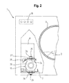
- FIGS. 2 to 6 in particular show details of the support body 10 of their special geometric design.
- each support body 10 is anisotropic in itself, by reacting differently to vibration loads in different directions perpendicular to its body axis.
- the support bodies can serve to initiate the outgoing from the functional part 8, initially perpendicular to the system axis 9 isotropic vibration load in the anisotropic base 7 so that a uniform, in particular isotropic, distribution of vibration loads in the base 7 is achieved.
- each support body 10 has a rectangular cross section perpendicular to its body axis 11.
- each support body 10 has a perpendicular to its body axis 11 oriented circular ring cylinder 20.
- Such a circular ring cylinder 20 has, see in particular FIGS. 5 and 6 , an outer diameter 21, an inner diameter 22 and a length 23, wherein the outer diameter 21 is approximately equal to the length 23 and the inner diameter 22 is approximately equal to half the outer diameter 21.
- each support body 10 consists of an entropy-elastic material, in particular vulcanized rubber having a hardness between 40 Shore A and 60 Shore A, and has contact plates 24 made of metal, each of which in turn has a fastening part 25, namely a threaded screw 25th
- the support body 10 can be attached to its screw threaded 25 by means of nuts 26 and washers 27 on the base 7 and on fastening tabs 28 of the functional part 8. In this way, vibration loads of the functional part 8 are transmitted to the base 7, in particular via the annular cylinders 20 of the support body 20.
- the support body 10 are aligned on the support plate 8 with respect to the base 7 and the system axis 9 with each other the same. They thus represent an anisotropic arrangement with respect to the system axis 9, which causes an anisotropic coupling of the functional part 8 to its anisotropic base. In this way, a compensation of the anisotropies can be achieved and an optimal vibration damping connection of the functional part 8 to the base 7 can be achieved.
Landscapes
- Engineering & Computer Science (AREA)
- Textile Engineering (AREA)
- Mechanical Engineering (AREA)
- General Engineering & Computer Science (AREA)
- Detail Structures Of Washing Machines And Dryers (AREA)
Abstract
Description
- Die Erfindung betrifft ein Haushaltsgerät umfassend ein über mehrere jeweils elastische Stützkörper auf einer ebenen Basis angebrachtes Funktionsteil, durch welches eine bezüglich einer vertikal zur Basis ausgerichteten Systemachse isotrope Schwingung erzeugbar ist, wobei die Basis bezüglich der Systemachse und senkrecht zu dieser anisotrop ist.
- Ein solches Haushaltsgerät geht hervor aus der
WO 2013/024127 A1 . Dort ist ein Haushaltsgerät beschreiben, welches als Wäschetrockner ausgestaltet ist, welcher eine Wärmepumpe des Kompressor-Typs beinhaltet. Der entsprechende Kompressor ist in einem Funktionsteil enthalten, in welches der Kompressor und eine elektrische Rotationsmaschine, die den Kompressor antreibt integriert sind. Das Funktionsteil hat eine im Wesentlichen zylindrische Form mit einigen Anbauten, die der Befestigung des Funktionsteils auf der Basis, dem Anschluss eines Leitungssystems zur Zu- und Abführung eines in der Wärmepumpe zirkulierenden Kältemittels sowie dem Anschluss allfällig notwendiger elektrischer Leitungen dienen. Die Systemachse ist die Drehachse der den Kompressor treibenden elektrischen Rotationsmaschine; sie ist auch die Drehachse des Kompressors selbst, da dieser Kompressor als Rollkolbenkompressor ausgestaltet ist. - Die Anbindung des Kompressors an die Basis gemäß
WO 2013/024127 A1 ist relativ steif, wobei wesentliche Relativbewegungen des Kompressors zur Basis weitgehend ausgeschlossen sind. Damit werden zwar Schwingungen des Kompressors gegen die Basis unterbunden, es werden aber die vom Kompressor verursachten Schwingungen in die Basis und damit verbundene weitere Komponenten des Haushaltsgeräts wie ein Gehäuse eingeleitet. Dadurch können im Gehäuse Dröhngeräusche hervorgerufen werden. - Demgemäß ist es die Aufgabe der Erfindung, ein Haushaltsgerät der eingangs definierten Gattung anzugeben, bei dem die Anbindung des Funktionsteils, insbesondere Kompressors, an die Basis weiterentwickelt ist.
- Zur Lösung dieser Aufgabe angegeben wird ein Haushaltsgerät mit den Merkmalen des unabhängigen Patentanspruchs. Bevorzugte Weiterbildungen sind Gegenstände der abhängigen Patentansprüche, nachfolgender Beschreibung und beigefügter Zeichnung.
- Erfindungsgemäß angegeben wird demnach ein Haushaltsgerät umfassend ein über mehrere jeweils elastische Stützkörper auf einer ebenen Basis angebrachtes Funktionsteil, durch welches eine bezüglich einer vertikal zur Basis ausgerichteten Systemachse isotrope Schwingung erzeugbar ist, wobei die Basis bezüglich der Systemachse und senkrecht zu dieser anisotrop ist; bei diesem Haushaltsgerät ist darüber hinaus jeder Stützkörper bezüglich einer jeweils zugehörigen und parallel zur Systemachse ausgerichteten Körperachse anisotrop elastisch, und die Anordnung der Stützkörper ist bezüglich der Systemachse anisotrop.
- Die Begriffe "bezüglich der Systemachse isotrop" und "bezüglich der Systemachse anisotrop" sind dabei so zu verstehen, dass Isotropie oder Anisotropie in Richtungen, die senkrecht zur Systemachse gerichtet sind, zu herrschen hat. Dies impliziert, dass im Falle solcher Isotropie Invarianz unter Rotationen um die Systemachse vorliegt, und im Falle solcher Anisotropie solche Invarianz nicht vorliegt
- Erfindungsgemäß wird demnach eine anisotrope Anbindung des Kompressors an die Basis geschaffen. Die Weichheit, oder ihr Gegenteil, die Festigkeit, der Anbindung des Funktionsteils an die Basis ist deshalb abhängig von der in der Ebene der Basis jeweils betrachteten Richtung. Dies ist besonders vorteilhaft deshalb, weil es Rücksicht nehmen kann auf die räumliche Verteilung der Schwingungsfähigkeit der Basis einerseits und auf räumliche Gegebenheiten, die ein Schwingen des Kompressors in unterschiedlichen Richtungen in unterschiedlichen Maßen erlauben mögen, andererseits.
- Bei einer bevorzugten Weiterbildung des erfindungsgemäßen Haushaltsgeräts ist das Funktionsteil eine elektrische Rotationsmaschine mit einer zugehörigen Rotationsachse, welche mit der Systemachse identisch ist, und weist eine von der elektrischen Rotationsmaschine antreibbare Gaskraftmaschine auf. Gemäß weiterer Bevorzugung ist diese Gaskraftmaschine eine thermodynamische Rotationsmaschine und weist eine zugehörige Rotationsachse auf, die mit der Systemachse identisch ist. Gemäß noch weiterer Bevorzugung ist diese Gaskraftmaschine ein Kompressor.
- Bei einer ebenfalls bevorzugten Weiterbildung des erfindungsgemäßen Haushaltsgeräts gehört die Gaskraftmaschine im Funktionsteil zu einer Wärmepumpe. Gemäß weiterer Bevorzugung umfasst die Wärmepumpe ein weich an die Gaskraftmaschine angeschlossenes Leitungssystem. "Weich" bedeutet dabei, dass das Leitungssystem Schwingungen des Funktionsteils aufnimmt, ohne die Schwingungseigenschaften des Funktionsteils dabei wesentlich zu beeinflussen.
- Bevorzugt ist das erfindungsgemäße Haushaltsgerät ein Gerät zur Pflege von Wäschestücken. Besonders in Betracht kommt dabei ein solches Gerät, welches ein Wäschetrockner ist; dieser Wäschetrockner mag mit weiterem Vorzug eine Wärmepumpe beinhalten.
- Bevorzugt hat im erfindungsgemäßen Haushaltsgerät jeder Stützkörper senkrecht zu seiner Körperachse einen rechteckigen Querschnitt. Dieser Querschnitt ergibt sich gemäß weiterer Bevorzugung daraus dass jeder Stützkörper einen senkrecht zu seiner Körperachse orientierten Kreisringzylinder aufweist. Gemäß noch weiter Bevorzugung weist der Kreisringzylinder einen Außendurchmesser, einen Innendurchmesser und eine Länge auf, wobei der Außendurchmesser etwa gleich der Länge und der Innendurchmesser etwa gleich dem halben Außendurchmesser ist. Dies bedeutet, dass die Anisotropie des Stützkörpers definiert ist durch die Anisotropie des Kreisringzylinders, welcher quer zu seiner Zylinderachse wesentlich leichter zu deformieren ist als in Richtung seiner Zylinderachse.
- Ebenfalls bevorzugt besteht im erfindungsgemäßen Haushaltsgerät jeder Stützkörper aus einem entropieelastischen Material und weist Kontaktplatten aus Metall auf, deren jede ein Befestigungselement aufweist. Mit weiterer Bevorzugung ist dabei jedes Befestigungselement ein Schraubgewindestück. Ebenfalls mit weiterer Bevorzugung ist das Material jedes Stützkörpers ein vulkanisierter Kautschuk. Mit noch weiterer Bevorzugung weist dieser Kautschuk eine Härte zwischen 40 Shore-A und 60 Shore-A auf.
- Außerdem bevorzugt sind im erfindungsgemäßen Haushaltsgerät die Stützkörper bezüglich der Basis und der Systemachse untereinander gleich ausgerichtet.
- Darüber hinaus bevorzugt weist im erfindungsgemäßen Haushaltsgerät das Funktionsteil eine Masse zwischen 3 kg und 8 kg auf.
- Bevorzugte Ausführungsbeispiele der Erfindung sind auch in den Figuren der beigefügten Zeichnung dargestellt, und sind nachfolgend auch detailliert erläutert. Es zeigen:
- Fig. 1
- Ein Haushaltsgerät, welches als Wäschetrockner ausgestaltet ist;
- Fig. 2
- eine Teilansicht des Haushaltsgeräts gemäß
Fig. 1 ; - Fig. 3
- eine Ansicht eines Befestigungsbleches mit Stützkörpern;
- Fig. 4
- eine Ansicht eines auf Stützkörper montierten Funktionsteils:
- Fig. 5
- eine Ansicht eines Stützkörpers; und
- Fig. 6
- Schnittbilder dieses Stützkörpers.
- Einander entsprechende Komponenten in den Figuren der Zeichnung sind jeweils mit dem gleichen Bezugszeichen versehen, um Übersicht zu schaffen und Referenzen zu mehreren Figuren gemeinsam zu ermöglichen.
-
Figur 1 zeigt ein Haushaltsgerät 1, welches als Wäschetrockner 1 zum Trocknen feuchter Wäschestücke 2 ausgestaltet ist. Dazu ist in dem Haushaltsgerät 1 eine rotierbare Trommel 3 angeordnet, welche die Wäschestücke 2 aufnimmt. Durch die Rotation der Trommel 3 mittels eines der Übersicht halber nicht dargestellten Motors werden die Wäschestücke in einem Strom erwärmter Prozessluft bewegt, damit diese Prozessluft die Feuchte aus ihnen aufnimmt und abführt. Dazu vorgesehen ist ein im wesentlichen in sich geschlossener Prozessluftkreislauf 4, in welchem die Prozessluft angetrieben von einem Prozessluftgebläse 5 zirkuliert und abwechselnd erwärmt und abgekühlt wird. Im Prozessluftkreislauf 4 vorgesehen ist auch ein Flusenfilter 6, mit welchem Splitter von Textilfasern und andere Partikel, die die Prozessluft den Wäschestücken 2 entreißt und die gewöhnlich als Flusen bezeichnet werden, aufgefangen werden, um nicht nachfolgende Teile im Prozessluftkreislauf 4 zu verschmutzen. Das Prozessluftgebläse 5, der Flusenfilter 6 und andere Teile des Prozessluftkreislaufs 4, zu denen nachfolgend Weiteres ausgeführt wird, sind in einer Basis 7 angeordnet, welche eine Bodengruppe 7 des Hausgeräts 1 bildet und welche als Träger aller weiteren Teile des Hausgeräts 1 fungiert. Die Trommel 3 ist oberhalb dieser Bodengruppe 7 angeordnet. - Auf einem ebenen Bereich der Bodengruppe 7 bzw. Basis 7, speziell auf einem Halteblech 7, das seinerseits fest mit der eigentlichen Bodengruppe verbunden ist, angebracht ist ein nachfolgend näher zu beschreibendes Funktionsteil 8, durch welches eine bezüglich einer vertikal zur Basis 7 ausgerichteten Systemachse 9 isotrope Schwingung erzeugbar ist. Die Basis 7 ist jedoch bezüglich der Systemachse 9 und senkrecht zu dieser anisotrop, was allerdings aufgrund der generell rechteckigen Gestalt der Basis 7 weitgehend selbstverständlich ist. Das Funktionsteil 8 ist dabei mittels Stützkörpern 10, die in
Figur 1 der Übersicht halber nicht dargestellt sind und bezüglich derer auf die weiteren Figuren der Zeichnung zu verweisen ist, auf dem Halteblech 7 angebracht. Jeder Stützkörper 10 ist dabei bezüglich einer jeweils zugehörigen und parallel zur Systemachse 9 ausgerichteten Körperachse 11 anisotrop elastisch, und dass die Anordnung der Stützkörper 10 bezüglich der Systemachse 9 anisotrop. - Das Halteblech 7 ist vorliegend vorgesehen, weil die eigentliche Bodengruppe aus Kunststoff gefertigt ist, eine direkte Verbindung des Funktionsteils 8 mit dem Kunststoff aber nicht erwünscht ist. Aufgrund einer festen Verbindung des Halteblechs 7 mit der übrigen Bodengruppe stellt dies aber im Hinblick auf die Behandlung von Schwingungsbelastungen, um die es vorliegend hauptsächlich geht, keine wesentliche Komplikation dar.
- Im vorliegenden Fall weist das Funktionsteil 8 eine elektrische Rotationsmaschine 12 mit einer zugehörigen Rotationsachse, welche mit der Systemachse 9 identisch ist, und eine von der elektrischen Rotationsmaschine 12 antreibbare Gaskraftmaschine 13, nämlich einen Kompressor 13 für ein in dem Wäschetrockner 1 zirkulierendes Kältemittel, auf. Diese Gaskraftmaschine 13 ist gemäß üblicher Praxis eine thermodynamische Rotationsmaschine 13, insbesondere eine Rollkolben-Maschine 13, und weist ihrerseits eine zugehörige Rotationsachse auf, die mit der Systemachse 9 identisch ist. Die Gaskraftmaschine 13 gehört dabei zu einer Wärmepumpe 13, 14, 15, 16, 17, mittels welcher die zum Trocknen der Wäschestücke 2 zirkulierende Prozessluft abwechseln erwärmt und gekühlt werden kann. Dazu umfasst die Wärmepumpe 13, 14, 15, 16, 17 zusätzlich ein weich an die Gaskraftmaschine 13 angeschlossenes Leitungssystem 14, welches gegen seien Umgebung geschlossen ist und in dem das Kältemittel zirkuliert, sowie einen Verflüssiger 15, in welchem das durch den Kompressor 13 in gasförmigem Zustand komprimierte Kältemittel unter Abgabe von Wärme an die Prozessluft verflüssigt wird, ein Entspannungsorgan 16, insbesondere eine Blende, ein Ventil oder eine Kapillare, in welchem der Binnendruck des flüssigen Kältemittels isenthalp reduziert wird, wobei es teilweise wieder verdampft, und ein Verdampfer 17, in dem das Kältemittel unter Aufnahme von Wärme aus der Prozessluft vollständig verdampft wird. Weitere Komponenten des Leitungssystems 14 mögen vorhanden sein, insbesondere ein Speicher oder ein Reiniger, sind aber der Übersicht halber nicht dargestellt. Der Verflüssiger dient dazu, die zirkulierende Prozessluft aufzuheizen, bevor sie in die Trommel 3 mit den zu trocknenden Wäschestücken eintritt und aus diesen Feuchtigkeit aufnimmt. Im Verdampfer 17 wird die aus der Trommel 3 ausgetretene, nun mit Feuchtigkeit beladene Prozessluft abgekühlt, so dass enthaltene Feuchtigkeit auskondensiert und im Kondensatsammler 18 gesammelt werden kann. Nachdem die Prozessluft den Verdampfer 17 durchströmt hat und von dem angefallenen Kondensat befreit ist, gelangt sie wiederum zum Verflüssiger, um erneut aufgeheizt und den zu trocknenden Wäschestücken 2 zugeführt zu werden.
- Bei seinem Betrieb geht aufgrund interner Unwuchten von dem Funktionsteil 8 eine Schwingungsbelastung aus, die einer um die Systemachse 9 rotierenden Unwucht entspricht und dementsprechend bezüglich der Systemachse 9 isotrop ist. Diese Schwingungsbelastung muss von einer geeigneten Anbindung des Funktionsteils 8 an die Basis 7 aufgefangen bzw. in die Basis 7 eingeleitet werden. Dabei ist insbesondere auf das Vorsehen einer geeigneten, also effektiv isotropen, Dämpfung zu achten. Gemäß üblicher Praxis hat das Funktionsteil 8 dabei eine Masse zwischen 3 kg und 8 kg.
- Eine Steuereinrichtung 19 dient der Steuerung des Wäschetrockners 1 und seine Komponenten, insbesondere einem (nicht dargestellten) Antrieb für die Trommel 3, Dem Gebläse 5 zum Fördern der zirkulierenden Prozessluft sowie dem Antrieb 12 des Kompressors 13. Weitere Komponenten mögen mit der Steuereinrichtung 19 verbunden sein, so zum Beispiel verschiedene Sensoren und ein Programmspeicher, in welchem verschiedene Programme zum Trocknen vom Wäschestücken 2 nach Art der Textilien, aus denen sie bestehen etc., oder eine Kommunikationseinrichtung, über die der Wäschetrockner 1 an ein Kommunikationsnetz angeschlossen wäre.
- Die
Figuren 2 bis 6 zeigen insbesondere Details der Stützkörper 10 ihrer speziellen geometrischen Auslegung. Vorliegend geht es vor allem darum, dass jeder Stützkörper 10 in sich anisotrop ist, indem er auf Schwingungsbelastungen in unterschiedlichen Richtungen senkrecht zu seiner Körperachse verschieden reagiert. Auf diese Weise können die Stützkörper dazu dienen, die von dem Funktionsteil 8 ausgehende, zunächst senkrecht zur Systemachse 9 isotrope Schwingungsbelastung derart in die an sich anisotrope Basis 7 einzuleiten, dass eine gleichmäßige, insbesondere isotrope, Verteilung der Schwingungsbelastungen in die Basis 7 erreicht wird. - Insbesondere zeigen die
Figuren 2 ,3 ,5 und 6 , dass jeder Stützkörper 10 senkrecht zu seiner Körperachse 11 einen rechteckigen Querschnitt hat. Außerdem weist jeder Stützkörper 10 einen senkrecht zu seiner Körperachse 11 orientierten Kreisringzylinder 20 auf. Ein solcher Kreisringzylinder 20 weist, siehe dazu besondersFiguren 5 und 6 , einen Außendurchmesser 21, einen Innendurchmesser 22 und eine Länge 23 auf, wobei der Außendurchmesser 21 etwa gleich der Länge 23 und der Innendurchmesser 22 etwa gleich dem halben Außendurchmesser 21 ist. Zudem besteht jeder Stützkörper 10 aus einem entropieelastischen Material, insbesondere vulkanisierten Kautschuk mit einer Härte zwischen 40 Shore-A und 60 Shore-A, und weist Kontaktplatten 24 aus Metall auf, deren jede ihrerseits ein Befestigungsteil 25 aufweist, und zwar ein Schraubgewindestück 25. - Wie insbesondere aus
Fig. 2 hervorgeht, können die Stützkörper 10 an ihren Schraubgewindestücken 25 mittels Muttern 26 und Unterlegscheiben 27 an der Basis 7 bzw. an Befestigungslaschen 28 des Funktionsteils 8 befestigt werden. Auf diese Weise werden Schwingungsbelastungen des Funktionsteils 8 insbesondere über die Kreisringzylinder 20 der Stützkörper 20 an die Basis 7 übertragen. - Wie dargestellt in den
Figuren 3 und4 sind die Stützkörper 10 Auf dem Halteblech 8 bezüglich der Basis 7 und der Systemachse 9 untereinander gleich ausgerichtet. Sie stellen damit eine bezüglich der Systemachse 9 anisotrope Anordnung dar, die eine anisotrope Ankopplung des Funktionsteils 8 an die ihrerseits anisotrope Basis bewirkt. Auf diese Weise kann ein Ausgleich der Anisotropien erreicht und eine optimal schwingungsdämpfende Anbindung des Funktionsteils 8 an die Basis 7 erreicht werden. -
- 1
- Haushaltsgerät, Wäschetrockner
- 2
- Wäschestück
- 3
- Trommel
- 4
- Prozessluftkreislauf
- 5
- Prozessluftgebläse
- 6
- Flusenfilter
- 7
- Basis, Bodengruppe, Halteblech
- 8
- Funktionsteil
- 9
- Systemachse
- 10
- Stützkörper
- 11
- Körperachse
- 12
- Elektrische Rotationsmaschine
- 13
- Gaskraftmaschine, Kompressor
- 14
- Leitungssystem
- 15
- Wärmequelle, Verflüssiger
- 16
- Entspannungsorgan
- 17
- Wärmesenke, Verdampfer
- 18
- Kondensatsammler
- 19
- Steuereinrichtung
- 20
- Kreisringzylinder
- 21
- Außendurchmesser
- 22
- Innendurchmesser
- 23
- Länge
- 24
- Kontaktplatte
- 25
- Befestigungsteil, Schraubgewindestück
- 26
- Mutter
- 27
- Unterlegscheibe
- 28
- Befestigungslasche
- 29
- Zwischenstück
Claims (16)
- Haushaltsgerät (1) umfassend ein über mehrere jeweils elastische Stützkörper (10) auf einer ebenen Basis (7) angebrachtes Funktionsteil (8), durch welches eine bezüglich einer vertikal zur Basis (7) ausgerichteten Systemachse (9) isotrope Schwingung erzeugbar ist, wobei die Basis (7) bezüglich der Systemachse (9) und senkrecht zu dieser anisotrop ist, dadurch gekennzeichnet, dass jeder Stützkörper (10) bezüglich einer jeweils zugehörigen und parallel zur Systemachse (9) ausgerichteten Körperachse (11) anisotrop elastisch ist, und dass die Anordnung der Stützkörper (10) bezüglich der Systemachse (9) anisotrop ist.
- Haushaltsgerät (1) nach Anspruch 1, bei dem das Funktionsteil (8) eine elektrische Rotationsmaschine (12) mit einer zugehörigen Rotationsachse, welche mit der Systemachse (9) identisch ist, und eine von der elektrischen Rotationsmaschine (12) antreibbare Gaskraftmaschine (13) aufweist.
- Haushaltsgerät (1) nach Anspruch 2, bei dem die Gaskraftmaschine (13) eine thermodynamische Rotationsmaschine (13) ist und eine zugehörige Rotationsachse aufweist, die mit der Systemachse (9) identisch ist.
- Haushaltsgerät nach einem der Ansprüche 2 und 3, bei dem die Gaskraftmaschine (13) ein Kompressor (13) ist.
- Haushaltsgerät (1) nach einem der Ansprüche 2 bis 4, bei dem die Gaskraftmaschine (13) zu einer Wärmepumpe (13, 14, 15, 16, 17) gehört.
- Haushaltsgerät (1) nach Anspruch 5, bei dem die Wärmepumpe (13, 14, 15, 16, 17) ein weich an die Gaskraftmaschine (13) angeschlossenes Leitungssystem (14) umfasst.
- Haushaltsgerät (1) nach einem der vorigen Ansprüche, welches ein Gerät (1) zur Pflege von Wäschestücken (2) ist.
- Haushaltsgerät (1) nach einem der vorigen Ansprüche, bei dem jeder Stützkörper (10) senkrecht zu seiner Körperachse (11) einen rechteckigen Querschnitt hat.
- Haushaltsgerät (1) nach Anspruch 7, bei dem jeder Stützkörper (10) einen senkrecht zu seiner Körperachse (11) orientierten Kreisringzylinder (20) aufweist.
- Haushaltsgerät (1) nach Anspruch 8, bei dem der Kreisringzylinder (20) einen Außendurchmesser (21), einen Innendurchmesser (22) und eine Länge (23) aufweist, wobei der Außendurchmesser (21) etwa gleich der Länge (23) und der Innendurchmesser (22) etwa gleich dem halben Außendurchmesser (21) ist.
- Haushaltsgerät (1) nach einem der vorigen Ansprüche, bei dem jeder Stützkörper (10) aus einem entropieelastischen Material besteht und Kontaktplatten (24) aus Metall aufweist, deren jede ein Befestigungsteil (25) aufweist.
- Haushaltsgerät (1) nach Anspruch 10, bei dem jedes Befestigungsteil (25) ein Schraubgewindestück (25) ist.
- Haushaltsgerät (1) nach einem der Ansprüche 10 und 11, bei dem das Material jedes Stützkörpers (10) ein vulkanisierter Kautschuk ist.
- Haushaltsgerät (1) nach Anspruch 12, bei dem der Kautschuk eine Härte zwischen 40 Shore-A und 60 Shore-A aufweist.
- Haushaltsgerät (1) nach einem der vorigen Ansprüche, bei der die Stützkörper (10) bezüglich der Basis (7) und der Systemachse (9) untereinander gleich ausgerichtet sind.
- Haushaltsgerät (1) nach einem der vorigen Ansprüche, bei dem das Funktionsteil (8) eine Masse zwischen 3 kg und 8 kg aufweist.
Priority Applications (1)
| Application Number | Priority Date | Filing Date | Title |
|---|---|---|---|
| PL14197515T PL2886709T3 (pl) | 2013-12-18 | 2014-12-12 | Urządzenie gospodarstwa domowego obejmujące umieszczoną na równej podstawie część funkcyjną |
Applications Claiming Priority (2)
| Application Number | Priority Date | Filing Date | Title |
|---|---|---|---|
| DE102013226398.8A DE102013226398A1 (de) | 2013-12-18 | 2013-12-18 | Haushaltsgerät umfassend ein auf einer ebenen Basis angebrachtes Funktionsteil |
| DE202014000975.9U DE202014000975U1 (de) | 2014-02-04 | 2014-02-04 | Haushaltsgerät umfassend ein auf einer ebenen Basis angebrachtes Funktionsteil |
Publications (2)
| Publication Number | Publication Date |
|---|---|
| EP2886709A1 true EP2886709A1 (de) | 2015-06-24 |
| EP2886709B1 EP2886709B1 (de) | 2021-09-08 |
Family
ID=52021109
Family Applications (1)
| Application Number | Title | Priority Date | Filing Date |
|---|---|---|---|
| EP14197515.1A Active EP2886709B1 (de) | 2013-12-18 | 2014-12-12 | Haushaltsgerät umfassend ein auf einer ebenen Basis angebrachtes Funktionsteil |
Country Status (2)
| Country | Link |
|---|---|
| EP (1) | EP2886709B1 (de) |
| PL (1) | PL2886709T3 (de) |
Citations (7)
| Publication number | Priority date | Publication date | Assignee | Title |
|---|---|---|---|---|
| JPS58187635A (ja) * | 1982-04-26 | 1983-11-01 | Matsushita Electric Ind Co Ltd | 密閉型電動圧縮機の防振装置 |
| JPH08338366A (ja) * | 1995-06-13 | 1996-12-24 | Sanyo Electric Co Ltd | 縦型回転式圧縮機の支持装置 |
| JP2002070777A (ja) * | 2000-09-04 | 2002-03-08 | Sanyo Electric Co Ltd | 圧縮機の支持装置 |
| US6499714B1 (en) * | 2001-10-04 | 2002-12-31 | John R. Wike | System for and method of mounting compressors |
| US20040096341A1 (en) * | 2002-11-19 | 2004-05-20 | Shinn Fu Corporation | Vibration and displacement proof air compressor |
| WO2013024127A1 (en) | 2011-08-18 | 2013-02-21 | BSH Bosch und Siemens Hausgeräte GmbH | Household appliance comprising a driving unit for a heat pump |
| US20130056613A1 (en) * | 2009-06-05 | 2013-03-07 | Carrier Corporation | Grommet Mounting Assembly |
-
2014
- 2014-12-12 PL PL14197515T patent/PL2886709T3/pl unknown
- 2014-12-12 EP EP14197515.1A patent/EP2886709B1/de active Active
Patent Citations (7)
| Publication number | Priority date | Publication date | Assignee | Title |
|---|---|---|---|---|
| JPS58187635A (ja) * | 1982-04-26 | 1983-11-01 | Matsushita Electric Ind Co Ltd | 密閉型電動圧縮機の防振装置 |
| JPH08338366A (ja) * | 1995-06-13 | 1996-12-24 | Sanyo Electric Co Ltd | 縦型回転式圧縮機の支持装置 |
| JP2002070777A (ja) * | 2000-09-04 | 2002-03-08 | Sanyo Electric Co Ltd | 圧縮機の支持装置 |
| US6499714B1 (en) * | 2001-10-04 | 2002-12-31 | John R. Wike | System for and method of mounting compressors |
| US20040096341A1 (en) * | 2002-11-19 | 2004-05-20 | Shinn Fu Corporation | Vibration and displacement proof air compressor |
| US20130056613A1 (en) * | 2009-06-05 | 2013-03-07 | Carrier Corporation | Grommet Mounting Assembly |
| WO2013024127A1 (en) | 2011-08-18 | 2013-02-21 | BSH Bosch und Siemens Hausgeräte GmbH | Household appliance comprising a driving unit for a heat pump |
Also Published As
| Publication number | Publication date |
|---|---|
| EP2886709B1 (de) | 2021-09-08 |
| PL2886709T3 (pl) | 2022-02-28 |
Similar Documents
| Publication | Publication Date | Title |
|---|---|---|
| DE112011106123B3 (de) | Wäschevorrichtung | |
| DE202012009608U1 (de) | Stylersystem für mehrere Kleidungsstücke | |
| DE102014105453A1 (de) | Wäschebehandlungsvorrichtung | |
| DE102008054497A1 (de) | Flügelrad für einen Ventilator | |
| DE202014000975U1 (de) | Haushaltsgerät umfassend ein auf einer ebenen Basis angebrachtes Funktionsteil | |
| DE102005018044C5 (de) | Trommelwaschmaschine mit Wäschetrocknungsfunktion | |
| EP2628838B1 (de) | Haushaltgerät mit einer Trocknungseinrichtung | |
| DE202012007190U1 (de) | Pumpe mit einer Vibrations-Dämpfungs-Halte-Vorrichtung | |
| EP3462052B1 (de) | Federeinrichtung zur federnden lagerung einer funktionseinheit eines elektrogeräts und verfahren zur beeinflussung einer solchen federeinrichtung | |
| EP3126564B1 (de) | Haushaltsgerät umfassend ein auf einer ebenen basis angebrachtes funktionsteil | |
| DE102013226398A1 (de) | Haushaltsgerät umfassend ein auf einer ebenen Basis angebrachtes Funktionsteil | |
| DE102010028437A1 (de) | Waschmaschine mit feststehendem Laugenbehälter und Verfahren zu ihrem Betrieb | |
| DE69208143T2 (de) | Steckbarer Lagerungsring | |
| EP2886709B1 (de) | Haushaltsgerät umfassend ein auf einer ebenen Basis angebrachtes Funktionsteil | |
| EP3129540B1 (de) | Trockner mit einer vibrationsarmen wärmepumpe und verfahren zu seinem betrieb | |
| WO2016162160A1 (de) | Schwingungsdämpfung eines antriebs einer wärmepumpe eines haushaltsgeräts | |
| DE102014204520B4 (de) | Trommel zum Pflegen von Wäschestücken mit zumindest einem Mitnehmer, sowie Maschine mit einer solchen | |
| DE102007052079A1 (de) | Ablufttrockner mit Wärmerückgewinnung und Kondensatwanne sowie Verfahren zu seinem Betrieb | |
| DE102009028011A1 (de) | Hausgerät mit einem elektrischen Motor | |
| DE102014107695A1 (de) | Verfahren zum betreiben einer wäschebehandlungsvorrichtung | |
| DE10331949B3 (de) | Haushaltswäschetrockner | |
| WO2002086235A1 (de) | Trommelvorrichtung mit durchlässigem trommelmantel und gespannt aufgezogenem siebgewebe | |
| DE102014118835A1 (de) | Wärmepumpenvorrichtung für ein Wäschebehandlungsgerät, Wäschebehandlungsgerät und Verfahren zum Herstellen eines Wäschebehandlungsgeräts | |
| EP3154165A1 (de) | Schwungradeinheit mit dämpfungseinrichtung | |
| EP3919838B1 (de) | Haushaltsgerät, insbesondere wäschetrockner, mit einer wärmepumpe umfassend eine expansionseinrichtung |
Legal Events
| Date | Code | Title | Description |
|---|---|---|---|
| PUAI | Public reference made under article 153(3) epc to a published international application that has entered the european phase |
Free format text: ORIGINAL CODE: 0009012 |
|
| 17P | Request for examination filed |
Effective date: 20141212 |
|
| AK | Designated contracting states |
Kind code of ref document: A1 Designated state(s): AL AT BE BG CH CY CZ DE DK EE ES FI FR GB GR HR HU IE IS IT LI LT LU LV MC MK MT NL NO PL PT RO RS SE SI SK SM TR |
|
| AX | Request for extension of the european patent |
Extension state: BA ME |
|
| R17P | Request for examination filed (corrected) |
Effective date: 20160104 |
|
| RBV | Designated contracting states (corrected) |
Designated state(s): AL AT BE BG CH CY CZ DE DK EE ES FI FR GB GR HR HU IE IS IT LI LT LU LV MC MK MT NL NO PL PT RO RS SE SI SK SM TR |
|
| GRAP | Despatch of communication of intention to grant a patent |
Free format text: ORIGINAL CODE: EPIDOSNIGR1 |
|
| STAA | Information on the status of an ep patent application or granted ep patent |
Free format text: STATUS: GRANT OF PATENT IS INTENDED |
|
| INTG | Intention to grant announced |
Effective date: 20210430 |
|
| GRAS | Grant fee paid |
Free format text: ORIGINAL CODE: EPIDOSNIGR3 |
|
| GRAA | (expected) grant |
Free format text: ORIGINAL CODE: 0009210 |
|
| STAA | Information on the status of an ep patent application or granted ep patent |
Free format text: STATUS: THE PATENT HAS BEEN GRANTED |
|
| AK | Designated contracting states |
Kind code of ref document: B1 Designated state(s): AL AT BE BG CH CY CZ DE DK EE ES FI FR GB GR HR HU IE IS IT LI LT LU LV MC MK MT NL NO PL PT RO RS SE SI SK SM TR |
|
| REG | Reference to a national code |
Ref country code: GB Ref legal event code: FG4D Free format text: NOT ENGLISH |
|
| REG | Reference to a national code |
Ref country code: CH Ref legal event code: EP Ref country code: AT Ref legal event code: REF Ref document number: 1428699 Country of ref document: AT Kind code of ref document: T Effective date: 20210915 |
|
| REG | Reference to a national code |
Ref country code: DE Ref legal event code: R096 Ref document number: 502014015868 Country of ref document: DE |
|
| REG | Reference to a national code |
Ref country code: IE Ref legal event code: FG4D Free format text: LANGUAGE OF EP DOCUMENT: GERMAN |
|
| REG | Reference to a national code |
Ref country code: NL Ref legal event code: FP |
|
| REG | Reference to a national code |
Ref country code: LT Ref legal event code: MG9D |
|
| PG25 | Lapsed in a contracting state [announced via postgrant information from national office to epo] |
Ref country code: LT Free format text: LAPSE BECAUSE OF FAILURE TO SUBMIT A TRANSLATION OF THE DESCRIPTION OR TO PAY THE FEE WITHIN THE PRESCRIBED TIME-LIMIT Effective date: 20210908 Ref country code: BG Free format text: LAPSE BECAUSE OF FAILURE TO SUBMIT A TRANSLATION OF THE DESCRIPTION OR TO PAY THE FEE WITHIN THE PRESCRIBED TIME-LIMIT Effective date: 20211208 Ref country code: ES Free format text: LAPSE BECAUSE OF FAILURE TO SUBMIT A TRANSLATION OF THE DESCRIPTION OR TO PAY THE FEE WITHIN THE PRESCRIBED TIME-LIMIT Effective date: 20210908 Ref country code: FI Free format text: LAPSE BECAUSE OF FAILURE TO SUBMIT A TRANSLATION OF THE DESCRIPTION OR TO PAY THE FEE WITHIN THE PRESCRIBED TIME-LIMIT Effective date: 20210908 Ref country code: NO Free format text: LAPSE BECAUSE OF FAILURE TO SUBMIT A TRANSLATION OF THE DESCRIPTION OR TO PAY THE FEE WITHIN THE PRESCRIBED TIME-LIMIT Effective date: 20211208 Ref country code: HR Free format text: LAPSE BECAUSE OF FAILURE TO SUBMIT A TRANSLATION OF THE DESCRIPTION OR TO PAY THE FEE WITHIN THE PRESCRIBED TIME-LIMIT Effective date: 20210908 Ref country code: RS Free format text: LAPSE BECAUSE OF FAILURE TO SUBMIT A TRANSLATION OF THE DESCRIPTION OR TO PAY THE FEE WITHIN THE PRESCRIBED TIME-LIMIT Effective date: 20210908 Ref country code: SE Free format text: LAPSE BECAUSE OF FAILURE TO SUBMIT A TRANSLATION OF THE DESCRIPTION OR TO PAY THE FEE WITHIN THE PRESCRIBED TIME-LIMIT Effective date: 20210908 |
|
| PG25 | Lapsed in a contracting state [announced via postgrant information from national office to epo] |
Ref country code: LV Free format text: LAPSE BECAUSE OF FAILURE TO SUBMIT A TRANSLATION OF THE DESCRIPTION OR TO PAY THE FEE WITHIN THE PRESCRIBED TIME-LIMIT Effective date: 20210908 Ref country code: GR Free format text: LAPSE BECAUSE OF FAILURE TO SUBMIT A TRANSLATION OF THE DESCRIPTION OR TO PAY THE FEE WITHIN THE PRESCRIBED TIME-LIMIT Effective date: 20211209 |
|
| PG25 | Lapsed in a contracting state [announced via postgrant information from national office to epo] |
Ref country code: IS Free format text: LAPSE BECAUSE OF FAILURE TO SUBMIT A TRANSLATION OF THE DESCRIPTION OR TO PAY THE FEE WITHIN THE PRESCRIBED TIME-LIMIT Effective date: 20220108 Ref country code: SM Free format text: LAPSE BECAUSE OF FAILURE TO SUBMIT A TRANSLATION OF THE DESCRIPTION OR TO PAY THE FEE WITHIN THE PRESCRIBED TIME-LIMIT Effective date: 20210908 Ref country code: SK Free format text: LAPSE BECAUSE OF FAILURE TO SUBMIT A TRANSLATION OF THE DESCRIPTION OR TO PAY THE FEE WITHIN THE PRESCRIBED TIME-LIMIT Effective date: 20210908 Ref country code: RO Free format text: LAPSE BECAUSE OF FAILURE TO SUBMIT A TRANSLATION OF THE DESCRIPTION OR TO PAY THE FEE WITHIN THE PRESCRIBED TIME-LIMIT Effective date: 20210908 Ref country code: PT Free format text: LAPSE BECAUSE OF FAILURE TO SUBMIT A TRANSLATION OF THE DESCRIPTION OR TO PAY THE FEE WITHIN THE PRESCRIBED TIME-LIMIT Effective date: 20220110 Ref country code: EE Free format text: LAPSE BECAUSE OF FAILURE TO SUBMIT A TRANSLATION OF THE DESCRIPTION OR TO PAY THE FEE WITHIN THE PRESCRIBED TIME-LIMIT Effective date: 20210908 Ref country code: CZ Free format text: LAPSE BECAUSE OF FAILURE TO SUBMIT A TRANSLATION OF THE DESCRIPTION OR TO PAY THE FEE WITHIN THE PRESCRIBED TIME-LIMIT Effective date: 20210908 Ref country code: AL Free format text: LAPSE BECAUSE OF FAILURE TO SUBMIT A TRANSLATION OF THE DESCRIPTION OR TO PAY THE FEE WITHIN THE PRESCRIBED TIME-LIMIT Effective date: 20210908 |
|
| REG | Reference to a national code |
Ref country code: DE Ref legal event code: R097 Ref document number: 502014015868 Country of ref document: DE |
|
| REG | Reference to a national code |
Ref country code: DE Ref legal event code: R119 Ref document number: 502014015868 Country of ref document: DE |
|
| PLBE | No opposition filed within time limit |
Free format text: ORIGINAL CODE: 0009261 |
|
| STAA | Information on the status of an ep patent application or granted ep patent |
Free format text: STATUS: NO OPPOSITION FILED WITHIN TIME LIMIT |
|
| PG25 | Lapsed in a contracting state [announced via postgrant information from national office to epo] |
Ref country code: MC Free format text: LAPSE BECAUSE OF FAILURE TO SUBMIT A TRANSLATION OF THE DESCRIPTION OR TO PAY THE FEE WITHIN THE PRESCRIBED TIME-LIMIT Effective date: 20210908 Ref country code: DK Free format text: LAPSE BECAUSE OF FAILURE TO SUBMIT A TRANSLATION OF THE DESCRIPTION OR TO PAY THE FEE WITHIN THE PRESCRIBED TIME-LIMIT Effective date: 20210908 |
|
| REG | Reference to a national code |
Ref country code: CH Ref legal event code: PL |
|
| 26N | No opposition filed |
Effective date: 20220609 |
|
| GBPC | Gb: european patent ceased through non-payment of renewal fee |
Effective date: 20211212 |
|
| PG25 | Lapsed in a contracting state [announced via postgrant information from national office to epo] |
Ref country code: SI Free format text: LAPSE BECAUSE OF FAILURE TO SUBMIT A TRANSLATION OF THE DESCRIPTION OR TO PAY THE FEE WITHIN THE PRESCRIBED TIME-LIMIT Effective date: 20210908 |
|
| REG | Reference to a national code |
Ref country code: BE Ref legal event code: MM Effective date: 20211231 |
|
| PG25 | Lapsed in a contracting state [announced via postgrant information from national office to epo] |
Ref country code: LU Free format text: LAPSE BECAUSE OF NON-PAYMENT OF DUE FEES Effective date: 20211212 Ref country code: IE Free format text: LAPSE BECAUSE OF NON-PAYMENT OF DUE FEES Effective date: 20211212 Ref country code: GB Free format text: LAPSE BECAUSE OF NON-PAYMENT OF DUE FEES Effective date: 20211212 Ref country code: DE Free format text: LAPSE BECAUSE OF NON-PAYMENT OF DUE FEES Effective date: 20220701 |
|
| PG25 | Lapsed in a contracting state [announced via postgrant information from national office to epo] |
Ref country code: FR Free format text: LAPSE BECAUSE OF NON-PAYMENT OF DUE FEES Effective date: 20211231 Ref country code: BE Free format text: LAPSE BECAUSE OF NON-PAYMENT OF DUE FEES Effective date: 20211231 |
|
| PG25 | Lapsed in a contracting state [announced via postgrant information from national office to epo] |
Ref country code: LI Free format text: LAPSE BECAUSE OF NON-PAYMENT OF DUE FEES Effective date: 20211231 Ref country code: CH Free format text: LAPSE BECAUSE OF NON-PAYMENT OF DUE FEES Effective date: 20211231 |
|
| PG25 | Lapsed in a contracting state [announced via postgrant information from national office to epo] |
Ref country code: IT Free format text: LAPSE BECAUSE OF FAILURE TO SUBMIT A TRANSLATION OF THE DESCRIPTION OR TO PAY THE FEE WITHIN THE PRESCRIBED TIME-LIMIT Effective date: 20210908 |
|
| PGFP | Annual fee paid to national office [announced via postgrant information from national office to epo] |
Ref country code: NL Payment date: 20221220 Year of fee payment: 9 |
|
| REG | Reference to a national code |
Ref country code: AT Ref legal event code: MM01 Ref document number: 1428699 Country of ref document: AT Kind code of ref document: T Effective date: 20211212 |
|
| PG25 | Lapsed in a contracting state [announced via postgrant information from national office to epo] |
Ref country code: AT Free format text: LAPSE BECAUSE OF NON-PAYMENT OF DUE FEES Effective date: 20211212 |
|
| PG25 | Lapsed in a contracting state [announced via postgrant information from national office to epo] |
Ref country code: HU Free format text: LAPSE BECAUSE OF FAILURE TO SUBMIT A TRANSLATION OF THE DESCRIPTION OR TO PAY THE FEE WITHIN THE PRESCRIBED TIME-LIMIT; INVALID AB INITIO Effective date: 20141212 |
|
| PG25 | Lapsed in a contracting state [announced via postgrant information from national office to epo] |
Ref country code: CY Free format text: LAPSE BECAUSE OF FAILURE TO SUBMIT A TRANSLATION OF THE DESCRIPTION OR TO PAY THE FEE WITHIN THE PRESCRIBED TIME-LIMIT Effective date: 20210908 |
|
| PG25 | Lapsed in a contracting state [announced via postgrant information from national office to epo] |
Ref country code: MK Free format text: LAPSE BECAUSE OF FAILURE TO SUBMIT A TRANSLATION OF THE DESCRIPTION OR TO PAY THE FEE WITHIN THE PRESCRIBED TIME-LIMIT Effective date: 20210908 |
|
| REG | Reference to a national code |
Ref country code: NL Ref legal event code: MM Effective date: 20240101 |
|
| PG25 | Lapsed in a contracting state [announced via postgrant information from national office to epo] |
Ref country code: NL Free format text: LAPSE BECAUSE OF NON-PAYMENT OF DUE FEES Effective date: 20240101 |
|
| PG25 | Lapsed in a contracting state [announced via postgrant information from national office to epo] |
Ref country code: NL Free format text: LAPSE BECAUSE OF NON-PAYMENT OF DUE FEES Effective date: 20240101 Ref country code: MT Free format text: LAPSE BECAUSE OF FAILURE TO SUBMIT A TRANSLATION OF THE DESCRIPTION OR TO PAY THE FEE WITHIN THE PRESCRIBED TIME-LIMIT Effective date: 20210908 |
|
| PGFP | Annual fee paid to national office [announced via postgrant information from national office to epo] |
Ref country code: PL Payment date: 20241206 Year of fee payment: 11 |
|
| PGFP | Annual fee paid to national office [announced via postgrant information from national office to epo] |
Ref country code: TR Payment date: 20241204 Year of fee payment: 11 |