EP2886480B1 - Behälter mit verborgenem scharnier sowie scharnierbefestigungsstruktur dafür - Google Patents
Behälter mit verborgenem scharnier sowie scharnierbefestigungsstruktur dafür Download PDFInfo
- Publication number
- EP2886480B1 EP2886480B1 EP13828228.0A EP13828228A EP2886480B1 EP 2886480 B1 EP2886480 B1 EP 2886480B1 EP 13828228 A EP13828228 A EP 13828228A EP 2886480 B1 EP2886480 B1 EP 2886480B1
- Authority
- EP
- European Patent Office
- Prior art keywords
- hinge
- grooves
- container
- door
- hidden
- Prior art date
- Legal status (The legal status is an assumption and is not a legal conclusion. Google has not performed a legal analysis and makes no representation as to the accuracy of the status listed.)
- Active
Links
Images







Classifications
-
- E—FIXED CONSTRUCTIONS
- E05—LOCKS; KEYS; WINDOW OR DOOR FITTINGS; SAFES
- E05D—HINGES OR SUSPENSION DEVICES FOR DOORS, WINDOWS OR WINGS
- E05D7/00—Hinges or pivots of special construction
-
- B—PERFORMING OPERATIONS; TRANSPORTING
- B65—CONVEYING; PACKING; STORING; HANDLING THIN OR FILAMENTARY MATERIAL
- B65D—CONTAINERS FOR STORAGE OR TRANSPORT OF ARTICLES OR MATERIALS, e.g. BAGS, BARRELS, BOTTLES, BOXES, CANS, CARTONS, CRATES, DRUMS, JARS, TANKS, HOPPERS, FORWARDING CONTAINERS; ACCESSORIES, CLOSURES, OR FITTINGS THEREFOR; PACKAGING ELEMENTS; PACKAGES
- B65D25/00—Details of other kinds or types of rigid or semi-rigid containers
- B65D25/005—Side walls formed with an aperture or a movable portion arranged to allow removal or insertion of contents
-
- B—PERFORMING OPERATIONS; TRANSPORTING
- B65—CONVEYING; PACKING; STORING; HANDLING THIN OR FILAMENTARY MATERIAL
- B65D—CONTAINERS FOR STORAGE OR TRANSPORT OF ARTICLES OR MATERIALS, e.g. BAGS, BARRELS, BOTTLES, BOXES, CANS, CARTONS, CRATES, DRUMS, JARS, TANKS, HOPPERS, FORWARDING CONTAINERS; ACCESSORIES, CLOSURES, OR FITTINGS THEREFOR; PACKAGING ELEMENTS; PACKAGES
- B65D90/00—Component parts, details or accessories for large containers
- B65D90/008—Doors for containers, e.g. ISO-containers
-
- E—FIXED CONSTRUCTIONS
- E05—LOCKS; KEYS; WINDOW OR DOOR FITTINGS; SAFES
- E05D—HINGES OR SUSPENSION DEVICES FOR DOORS, WINDOWS OR WINGS
- E05D5/00—Construction of single parts, e.g. the parts for attachment
- E05D5/02—Parts for attachment, e.g. flaps
- E05D5/0215—Parts for attachment, e.g. flaps for attachment to profile members or the like
- E05D5/0223—Parts for attachment, e.g. flaps for attachment to profile members or the like with parts, e.g. screws, extending through the profile wall or engaging profile grooves
-
- E—FIXED CONSTRUCTIONS
- E05—LOCKS; KEYS; WINDOW OR DOOR FITTINGS; SAFES
- E05D—HINGES OR SUSPENSION DEVICES FOR DOORS, WINDOWS OR WINGS
- E05D7/00—Hinges or pivots of special construction
- E05D7/12—Hinges or pivots of special construction to allow easy detachment of the hinge from the wing or the frame
- E05D7/123—Hinges or pivots of special construction to allow easy detachment of the hinge from the wing or the frame specially adapted for cabinets or furniture
- E05D7/125—Hinges or pivots of special construction to allow easy detachment of the hinge from the wing or the frame specially adapted for cabinets or furniture the hinge having two or more pins
-
- E—FIXED CONSTRUCTIONS
- E05—LOCKS; KEYS; WINDOW OR DOOR FITTINGS; SAFES
- E05D—HINGES OR SUSPENSION DEVICES FOR DOORS, WINDOWS OR WINGS
- E05D3/00—Hinges with pins
- E05D3/06—Hinges with pins with two or more pins
- E05D3/12—Hinges with pins with two or more pins with two parallel pins and one arm
-
- E—FIXED CONSTRUCTIONS
- E05—LOCKS; KEYS; WINDOW OR DOOR FITTINGS; SAFES
- E05Y—INDEXING SCHEME ASSOCIATED WITH SUBCLASSES E05D AND E05F, RELATING TO CONSTRUCTION ELEMENTS, ELECTRIC CONTROL, POWER SUPPLY, POWER SIGNAL OR TRANSMISSION, USER INTERFACES, MOUNTING OR COUPLING, DETAILS, ACCESSORIES, AUXILIARY OPERATIONS NOT OTHERWISE PROVIDED FOR, APPLICATION THEREOF
- E05Y2600/00—Mounting or coupling arrangements for elements provided for in this subclass
- E05Y2600/50—Mounting methods; Positioning
- E05Y2600/52—Toolless
- E05Y2600/53—Snapping
Definitions
- the present invention relates to containers with hinge fixing structures and hidden hinges used to fix hidden hinges to containers.
- containers to carry or transport various types of materials, and these containers are of a series of specifications from the big to the small.
- plastic containers become widespread.
- Such containers mostly have a bottom and integrated or foldable four side plates.
- a door that can be opened is usually provided at one or more side plates for easy access to items at the bottom of the container or for installation or disassembly of some additional components at the bottom of the container.
- the door that can be opened flushes with the side plate, and has a locking mechanism ensuring that it would not be accidentally opened.
- the door When it is needed to open the door, after being unlocked, the door is flipped outwardly by approximately 180 degrees and then is lean against the side plate substantially, so as to reduce the space it occupies, and makes it more convenient for people to operate through an opening of the side plate.
- FIG. 1 it uses a generally U-shaped hinge body, which is provide with at least two groups of hinge pins, respectively connected with the upper and lower hinge bases, wherein the upper hinge base is connected with the door and the lower hinge base is connected with the side plate.
- the upper and lower hinge base may both be rotated by 90 degrees around the hinge pins of the hinge body, in this way, the door could be flipped outwardly relative to the side plate by 180 degrees.
- the hinge body, the upper and lower hinge bases could be arranged within the thickness between the internal and external surfaces of the side plate. When the door is closed, the hinge is substantially invisible from the appearance of the container.
- the hidden hinge described above can greatly improve the overall product appearance, however, since there are hinge mounting holes provided at he hinge mounting parts of the side plate and the door, and the hinge mounting holes and the hinge positioning structures will still be seen from the appearance of the container after the hinge is installed. Further, since the hinge mounting holes are provided on the side plate and the door, and therefore, the strength of the hinge mounting parts on the side plate and the door is also affected to some extent.
- WO 2009/023830 A1 discloses a panel for a modular bulk container, the panel having a frame and a door pivotally attached to the frame by a hinge extendable from a portion of the frame.
- CN 102 582 912 A discloses a side-door closing HF (hands free) container, which comprises a bottom wall and side walls, wherein one or a plurality of side walls are provided with side doors; and the side doors are connected with the side walls by hinge devices.
- US 2009/152265 A1 discloses an apparatus and methods for hinging or otherwise easily engaging and disengaging various members to each other include a spring-actuated pin element to selectively extend and retract a pin from one hinge leaf to engage an adjacent structure.
- US 4 928 350 A disclose a hinge construction of two mounting plates and a substantially U-shaped centre link which connects the axes of pivot of the two plates, wherein the link and plates contain stop mechanisms which determine their respective limits of pivot.
- the object of the present invention is to provide a container with a structure used to hold a hidden hinge on the container, so that after installation, the hinge is completely invisible from the appearance of the container, and the disassembly of the hinge becomes more convenient.
- a container comprising a bottom, four integrated foldable side plates and a door provided on at least one of the side plates and a hidden hinge
- said hidden hinge comprises an upper hinge base, a hinge body and a lower hinge base
- said door and the at least one of said side plates are connected to each other through said hidden hinge
- said container further comprises a hinge fixing structure used to hold the hidden hinge on the container, and at least one of the side plates and the door which are respectively provided with grooves formed by the internal and external sidewalls thereof and used to accommodate the hinge bases
- said hinge fixing structure comprises: position limiting structures located in said grooves and used to prevent the hinge bases from releasing from mouth portions of said grooves respectively, and positioning structures provided on said upper hinge base and said lower hinge base and engaged with said position limiting structures respectively; wherein:said position limiting structures comprise positioning ribs located at the bottom of the grooves respectively, said position limiting structures are engaged with said positioning structures respectively so
- a container comprising a bottom, four integrated foldable side plates, a door provided on at least one of the side plates and a hidden hinge comprising an upper hinge base, a hinge body and a lower hinge base, wherein said door and the at least one of said side plates are connected to each other through said hidden hinge and wherein: said container further comprises a hinge fixing structure used to hold the hidden hinge on the container, and at least one of the side plates and the door which are respectively provided with grooves formed by the internal and external sidewalls thereof and used to accommodate the hinge bases, wherein said hinge fixing structure comprises: position limiting structures located in said grooves and used to prevent the hinge bases from releasing from mouth portions of said grooves respectively, and positioning structures provided on said upper hinge base and said lower hinge base and engaged with said position limiting structures respectively; wherein:
- said hanging protrusions are two protrusions extending integrally from one of the front and rear sides of each hinge base, and said hanging slots are two L-shaped slots, wherein said protrusions are engaged with said L-shaped slots to prevent the hinge base from releasing from said groove.
- a container comprising a bottom, four integrated foldable side plates, a door provided on at least one of the side plates and a hidden hinge comprising an upper hinge base, a hinge body and a lower hinge base, wherein said door and the at least one of said side plates are connected to each other through said hidden hinge and wherein: said container further comprises a hinge fixing structure used to hold the hidden hinge on the container, and at least one of the side plates and the door which are respectively provided with grooves formed by the internal and external sidewalls thereof and used to accommodate the hinge bases, wherein said hinge fixing structure comprises: position limiting structures located in said grooves and used to prevent the hinge bases from releasing from mouth portions of said grooves respectively, and positioning structures provided on said upper hinge base and said lower hinge base and engaged with said position limiting structures respectively; wherein: said position limiting structures are engaged with said positioning structures respectively so that said hidden hinge is held on the said container and said hidden hinge is completely invisible from the appearance of said container when the door is closed, said position
- said limiting projections are columnar members extending integrally from the bottom of the grooves; said positioning slots are slots provided at the front and rear sides of the hinge base respectively and said columnar members are snapped into said slots respectively; and said hanging protrusions are ribs projecting integrally from the left and right side of the hinge base respectively and said elastic hooks are L-shaped members, wherein said ribs are engaged with said elastic hooks respectively so as to prevent the hinge bases from releasing from the grooves.
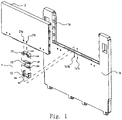
- FIG. 1 illustrates a schematic view of a prior art hidden hinge as well as a door and a side plate for mounting the hidden hinge. As shown in Fig.
- a hinge assembly 3 includes a hinge body 32, an upper hinge base 31 and a lower hinge base 33, wherein the hinge body 32 comprises upper hinge pins 321 and lower hinge pins 322. Grooves 312 in the upper hinge base 31 are used to accommodate the hinge pins 321 and grooves 332 in the lower hinge base 33 are used to accommodate the hinge pins 322. Hanging protrusions 311 are provided at a side portion of the upper hinge base 31 and hanging protrusions 331 are provided at a side portion of the lower hinge base 33.
- Holes 21 are provided at the sidewall of a door 2, and holes 1a1 are provided at the sidewall of a side plate 1a, thereby when the upper hinge base 31 and the door 2 are assembled, the sidewall of the door 2 which is squeezed by the hanging protrusions 311 will be deformed outwardly, which enables the hanging protrusions 311 to be inserted into the holes 21 respectively, thus prevents the upper hinge base 31 from easily releasing from the groove of door 2.
- FIG. 2-5 illustrates the hinge fixing structure according to the first aspect of the present invention. Compared with the fixing structure shown in Fig. 1 , the sidewalls are free of any holes, which not only improves the appearance of the container, but also increases the strength of the hinge mounting portion.
- the hinge assembly 3 has similar structure to that in Fig. 1 .
- the upper hinge base 31 are provided with two branches 311 and 312 with projections
- the lower hinge base 33 are provided with two branches 331 and 332 with projections.
- Branches 311, 312 and branches 331, 332 have similar structures, hereinafter only the branches 331, 332 provided at both sides of the lower hinge base will be described as examples.
- branches 331 and 332 are elastic pieces extending integrally from two sides 33a, 33b of the lower hinge base at lower surface 33c of the lower hinge base respectively, wherein projections 331a, 332a are provided at the ends of the elastic pieces.
- Projections 331a, 332a are used to engage with the hanging protrusions in the groove when the lower hinge base 31 is being installed into groove 1a1 of side plate 1a, such that the lower hinge base 33 are prevented from releasing from side plate 1a after the completion of installation, which will be described in detail below.
- Groove 1a1 is positioned between two sidewalls 1a20 and ia2i of the side plate 1a. Positioning ribs 1a11, 1a12 and hanging protrusions 1a13, 1a14 providing position limits are provided in the groove 1a1. As shown more clearly in Fig. 3 , positioning ribs 1a11, 1a12 are two columnar members extending outwardly from the bottom surface of the groove, wherein the cross section of the columnar members can be selected as desired. In this embodiment, the cross-sectional shape of the columnar members is rectangular.
- the distance between the positioning rib 1a11 and the positioning rib 1a12 can be determined according to the distance between the two branches 331 and 332 of the lower hinge base 33, so that the hinge base is prevented from moving left and right by the engagement between the positioning ribs and branches.
- the hanging protrusions 1a13, 1a14 are tabs extending from both sides of the mouth portion of the groove respectively.
- the groove 21 has the same structure as that of the groove 1a1, that is, positioning ribs 211, 212 and hanging protrusions 213, 214 are provided therein, and the hanging protrusions 213, 214 are respectively engaged with the branches 311 and 312, which prevents the upper hinge base from releasing from the groove 21.
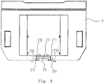
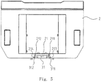
- Figs. 4 and 5 illustrate the process of installing the hinge assembly 3 provided with the hinge structure within the side plate 1a or the door 2.
- the positioning ribs 211, 212 will firstly contact with upper hinge base 31 so that they could not easily move left and right.
- the hanging protrusions 213, 214 of groove 21 prevent the branches 331, 332 from entering groove 21 so that the branches 331, 332 will be bent and deformed inwardly due to their own elasticity, as shown in Fig. 3 .
- the branches 331, 332 would be able to enter groove 21 when the distance between them is not greater than that between hanging protrusions 213, 214.
- the hanging protrusions 213, 214 limit the movement of the projections of the branches 331, 332 toward the mouth portion of the groove. Therefore, the installation of the upper hinge base 31 to the door 2 is realized.
- the lower hinge base 3 and the side plate 1a are assembled in the same manner, which will not be elaborated herein.
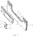
- Figs. 6-9 show the hinge fixing structure according to a second aspect of the present invention.
- the structure of the hinge assembly 3 is similar to that of the first aspect of the present invention, except the hinge fixing structure.
- the upper hinge base 31 is provided with hanging protrusions 314, 315 and elastic piece 313 providing a function of positioning.
- the lower hinge base 33 is also provided with hanging protrusions 334, 335 and elastic piece 333.
- the hanging protrusions 314 and 215 are respectively protrusions located at the left and right sides of the front (or rear) upper part of the upper hinge base, wherein the elastic piece 313 is a thin sheet extending integrally from the right (or left) upper part of the upper hinge base.
- Hanging protrusions 334, 335 of lower hinge base 33 are protrusions respectively located at left and right sides of the front (or rear) part of the lower hinge base, wherein the elastic piece 333 is a thin sheet extending integrally from the right upper part of the lower hinge base.
- the hanging protrusions described above are engaged with hanging slots in grooves of the door and side plate respectively, which prevents the hinge base from releasing from the mouth portion of the groove when the upper hinge base and the lower hinge base are installed respectively to the door and the side plate.
- the door 2 is provided with a groove 21 between two sidewalls, and L-shaped hanging slots 215, 216 providing the function of position limiting are provided within the groove 21.
- the side plate 1a is provided with a groove 1a1 between two sidewalls 1a20 and 1a21, and hanging slots 1a15, 1a16 are provided within the groove 1a1.
- the cross-sectional shape of the hanging slots 215, 216 matches the shape of hanging protrusions, and the distance between the hanging slots 215, 216 is determined by the distance between the hanging protrusions 314, 315, which enables the hanging protrusions 314, 315 to be engaged in the hanging slots 215, 216 and prevent them from releasing from the hanging slots.
- the hanging slots 1a15, 1a16 have the same structure as that of the hanging slots 215, 216, which will not be elaborated herein.
- FIGs 8-9 illustrate the process of installing the hinge assembly with the hinge fixing structure of the present aspect to the side plate 1a or the door 2. Only the process of installing the upper hinge base 31 to the door 2 is described as an example.
- the upper hinge base 31 When the upper hinge base 31 is installed in the groove 21 of the door 2, the upper hinge base 31 will slightly offset to the right at first, enabling the hanging protrusions 314, 315 to enter the hanging slots 215, 216 laterally. At this time, the elastic piece 313 of the upper hinge base 31 will be deformed downward due to the obstruction of lateral structure of groove 21, as shown in Fig. 8 . At this time, the upper hinge base 31 is further pushed toward the left side so that the hanging protrusions 314, 315 will enter the hanging slots 215, 216, then the elastic piece 313 is no longer blocked by the side structure of the groove 21 and restores its free-form.
- the elastic piece 313 can prevent the upper hinge base 31 from further moving to the right and from easily releasing from the hanging slots, (i.e., releasing from the groove 21), thereby achieving the installation of upper hinge base 31 to door 2.
- the lower hinge base 3 is installed to the side plate 1a in the same manner.
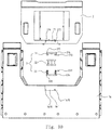
- Figs. 10-13 show the hinge fixing structure according to a third aspect of the present invention.
- the hinge assembly 3 has similar structure to that of the two aspects described above, except the hinge fixing structure.
- the upper hinge base 31 is provided with hanging protrusions 317a, 317b and positioning slots 318a, 318b.
- the lower hinge base 33 is also provided with hanging protrusions 337a, 337b and positioning slots 338a, 338b.
- the hanging protrusions 317a, 317b are respectively ribs projecting integrally from the left and right sides of the upper hinge base, and the positioning slots are slots substantially provided at the front and the rear sides at the middle of the upper hinge base.
- the hanging protrusions 337a, 337b of the lower hinge base 33 are protrusions respectively located at the left and right lower part of the lower hinge base, and the positioning slots 338 are slots provided at the front and the rear sides at the middle of the lower hinge base.
- the hanging protrusions and the positioning slots respectively are engaged with limiting projections and elastic hooks located in the door and the side plate respectively, which prevents the hinge bases from releasing from the mouth portion of the grooves when the upper hinge base and the lower hinge base are installed to the door and the side plate respectively.
- the door 2 is provided with a groove 21 located between two sidewalls, and the bottom of the groove 21 is provided with limiting projections 218a, 218b providing a function of position limiting.
- Elastic hooks 217a, 217b which are substantially L-shaped plate pieces, extend downward from the mouth portion of the groove.
- the side plate 1a is provided with a groove 1a1 between two sidewalls ia20, 1a21.
- the bottom of the groove 1a1 is provided with limiting projections iai8a, iai8b.
- elastic hooks 1a17a, 1a17b extend downward from the mouth portion of the groove.
- Limiting projections 218a, 218b are columnar members extending integrally from the bottom, whose shape and size are not with any special requirements, as long as they match those of the positioning slots 318a, 318b.
- the shape and size of elastic hooks 217a, 217b are neither with any special requirements, as long as they match those of hanging protrusions 317a, 317b, which enables the hanging protrusions 317a, 317b to snap into the elastic hooks 217a, 217b after installation and prevents them from releasing from the hanging slots.
- the elastic hooks 217a, 217b are substantially L-shaped.
- the limiting projections 1a18a, 1a18b and the elastic hooks 1a17a, 1a17b respectively have the same structure with that of the limiting projections 218a, 218b and the elastic hooks 217a, 217b, which will not be elaborated herein.
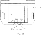
- Figs. 12-13 illustrate the process of installing the hinge assembly 3 with the hinge fixing structure of the present aspect to the side plate 1a or the door 2, here only the process of installing the upper hinge base 31 to the door 2 will be described as an example.
- the upper hinge base 31 When installing the upper hinge base 31 into the groove 21 of door 2, firstly the positioning slots 318a, 318b of the upper hinge base 31 are aligned with the limiting projections 218a, 218b in the groove 21 of the door 2 and the upper hinge base 31 is pressed into the groove 21. Then the hanging protrusions 317a, 317b of the upper hinge base 31 will press the elastic hooks 217a, 217b, which makes the elastic hooks to deform, thereby allowing the positioning slots 318a, 318b to enter the limiting projections 218a, 218b. When the positioning slots have entered the limiting projections completely, the elastic hooks 217a, 217b will restore their free-form. In this way, the elastic hooks 217a, 217b prevent the hinge base 31 from easily releasing from the groove 21, thereby finishing the installation of upper hinge base 31 to door 2.
- the lower hinge base 33 is installed to the side plate 1a in the same manner.
- the fixing structure used to hold hinges on the door or the side plate has advantages of simple structure, easy installation and improved appearance, since the hinge assembly would never been seen from the appearance when the door is closed after installation. Further, since the hinge is completely installed between two sidewalls of the door or the side plate, there are no hinge mounting holes on the sidewalls of the door and the side plate, which increases the strength of the hinge mounting portion of the door and the side plate to some extent.
Landscapes
- Engineering & Computer Science (AREA)
- Mechanical Engineering (AREA)
- Hinges (AREA)
- Rigid Containers With Two Or More Constituent Elements (AREA)
Claims (6)
- Behälter, umfassend einen Boden, vier integrierte faltbare Seitenplatten (1a), eine Tür (2), die an mindestens einer der Seitenplatten (1a) vorgesehen ist, und ein verborgenes Scharnier (3), das eine obere Scharnierbasis (31), einen Scharnierkörper (32) und eine untere Scharnierbasis (33) umfasst, wobei die Tür (2) und die mindestens eine der Seitenplatten (1a) durch das verborgene Scharnier (3) miteinander verbunden sind und wobei:der Behälter ferner eine Scharnierbefestigungsstruktur umfasst, die verwendet wird, um das verborgene Scharnier an dem Behälter zu halten, dadurch gekennzeichnet, dass mindestens eine der Seitenplatten (1a) und die Tür (2) jeweils mit Nuten (1a1, 21) versehen sind, die durch die inneren und äußeren Seitenwände davon gebildet werden und verwendet werden, um die Scharnierbasen (31, 33) aufzunehmen, wobei die Scharnierbefestigungsstruktur umfasst:
Positionsbegrenzungsstrukturen (1a13, 1a14, 213, 214), die in den Nuten (1a1, 21) angeordnet sind und verwendet werden, um zu verhindern, dass sich die Scharnierbasen (31, 33) jeweils von Öffnungsabschnitten der Nuten lösen, und Positionierungsstrukturen (311, 312, 331, 332), die auf der oberen Scharnierbasis (31) und der unteren Scharnierbasis (33) vorgesehen sind und jeweils mit den Positionsbegrenzungsstrukturen (1a13, 1a14, 213, 214) in Eingriff stehen; wobei:die Positionsbegrenzungsstrukturen (1a13, 1a14, 213, 214) Positionierungsrippen (1a11, 1a12, 211, 212) umfassen, die jeweils am Boden der Nuten (1a1, 21) angeordnet sind;die Positionsbegrenzungsstrukturen (1a13, 1a14, 213, 214) jeweils mit den Positionierungsstrukturen (311, 312, 331, 332) in Eingriff stehen, so dass das verborgene Scharnier (3) an dem Behälter gehalten wird und das verborgene Scharnier (3) für das Aussehen des Behälters völlig unsichtbar ist, wenn die Tür (2) geschlossen ist;die Positionierungsrippen (1a11, 1a12, 211, 212) verwendet werden, um zu verhindern, dass sich die Scharnierbasen (31, 33) herumbewegen;die Positionsbegrenzungsstrukturen (1a13, 1a14, 213, 214) hängende Vorsprünge (1a13, 1a14, 213, 214) umfassen, die sich jeweils an den Mündungsabschnitten der Nuten (1a1, 21) befinden;die Positionierungsstrukturen (331, 332) Zweige sind, die sich von der linken und rechten Seite der Scharnierbasen (31, 33) erstrecken; unddie Zweige elastische Stücke sind, die sich einstückig von der linken bzw. rechten Seite der Scharnierbasis erstrecken, und an den Enden der elastischen Stücke Vorsprünge vorgesehen sind; unddie hängenden Vorsprünge (1a13, 1a14, 213, 214) Laschen sind, die sich von beiden Seiten der Öffnungsabschnitte der Nuten erstrecken, wobei die Laschen jeweils mit den Vorsprüngen in Eingriff stehen, um zu verhindern, dass sich die Scharnierbasen aus den Nuten (1a1, 21) lösen. - Behälter nach Anspruch 1, wobei die Positionierungsrippen (1a11, 1a12) säulenförmige Elemente sind, die sich von den Bodenflächen der Nuten (1a1, 21) erstrecken, so dass die Scharnierbasen (31, 33) nach der Installation zwischen zwei säulenförmigen Elementen gehalten werden.
- Behälter, umfassend einen Boden, vier integrierte faltbare Seitenplatten (1a), eine Tür (2), die an mindestens einer der Seitenplatten (1a) vorgesehen ist, und ein verborgenes Scharnier (3), das eine obere Scharnierbasis (31), einen Scharnierkörper (32) und eine untere Scharnierbasis (33) umfasst, wobei die Tür (2) und die mindestens eine der Seitenplatten (1a) durch das verborgene Scharnier (3) miteinander verbunden sind und wobei:
der Behälter ferner eine Scharnierbefestigungsstruktur umfasst, die verwendet wird, um das verborgene Scharnier an dem Behälter zu halten, dadurch gekennzeichnet, dass mindestens eine der Seitenplatten (1a) und die Tür (2) jeweils mit Nuten (1a1, 21) versehen sind, die durch die inneren und äußeren Seitenwände davon gebildet werden und verwendet werden, um die Scharnierbasen (31, 33) aufzunehmen, wobei die Scharnierbefestigungsstruktur umfasst:
Positionsbegrenzungsstrukturen (1a13, 1a14, 213, 214), die in den Nuten (1a1, 21) angeordnet sind und verwendet werden, um zu verhindern, dass sich die Scharnierbasen (31, 33) jeweils von Öffnungsabschnitten der Nuten lösen, und Positionierungsstrukturen (311, 312, 331, 332), die auf der oberen Scharnierbasis (31) und der unteren Scharnierbasis (33) vorgesehen sind und jeweils mit den Positionsbegrenzungsstrukturen (1a13, 1a14, 213, 214) in Eingriff stehen; wobei:die Positionsbegrenzungsstrukturen (1a13, 1a14, 213, 214) jeweils mit den Positionierungsstrukturen (311, 312, 331, 332) in Eingriff stehen, so dass das verborgene Scharnier (3) an dem Behälter gehalten wird und das verborgene Scharnier (3) von dem Erscheinungsbild des Behälters vollständig unsichtbar ist, wenn die Tür (2) geschlossen ist,die genannten Positionsbegrenzungsstrukturen (1a13, 1a14, 213, 214) Hängeschlitze (1a15, 1a16, 215, 216) sind, die sich am Boden der Nuten (1a1, 21) befinden;die Positionierungsstrukturen (311, 312, 331,332) elastische Stücke (313, 333), die sich von der linken Seite oder der rechten Seite der Scharnierbasen (31, 33) erstrecken, und hängende Vorsprünge (314, 315, 334, 335) umfassen, die an der Vorderseite oder der Rückseite der Scharnierbasen (31, 33) vorgesehen sind; unddie Aufhängeschlitze (1a15, 1a16, 215, 216) jeweils mit den Aufhängevorsprüngen (314, 315, 334, 335) in Eingriff stehen, um zu verhindern, dass sich die Scharnierbasen (31, 32) aus den Nuten (1a1, 21) lösen. - Behälter nach Anspruch 3, wobei die hängenden Vorsprünge (314, 315, 334, 335) zwei Vorsprünge sind, die sich einstückig von einer der Vorder- und Rückseiten jeder Scharnierbasis (31, 33) erstrecken, und die hängenden Schlitze (1a15, 1a16, 215, 216) zwei L-förmige Schlitze sind, wobei die Vorsprünge (314, 315, 334, 335) mit den L-förmigen Schlitzen in Eingriff stehen, um zu verhindern, dass sich die Scharnierbasis (31, 33) aus der Nut (1a1, 21) löst.
- Behälter, umfassend einen Boden, vier integrierte faltbare Seitenplatten (1a), eine Tür (2), die an mindestens einer der Seitenplatten (1a) vorgesehen ist, und ein verborgenes Scharnier (3), das eine obere Scharnierbasis (31), einen Scharnierkörper (32) und eine untere Scharnierbasis (33) umfasst, wobei die Tür (2) und die mindestens eine der Seitenplatten (1a) durch das verborgene Scharnier (3) miteinander verbunden sind und wobei:der Behälter ferner eine Scharnierbefestigungsstruktur umfasst, die verwendet wird, um das versteckte Scharnier an dem Behälter zu halten, dadurch gekennzeichnet, dass mindestens eine der Seitenplatten (1a) und die Tür (2) jeweils mit Nuten (1a1, 21) versehen sind, die durch die inneren und äußeren Seitenwände davon gebildet werden und verwendet werden, um die Scharnierbasen (31, 33) aufzunehmen, wobei die Scharnierbefestigungsstruktur umfasst:
Positionsbegrenzungsstrukturen (1a13, 1a14, 213, 214), die in den Nuten (1a1, 21) angeordnet sind und verwendet werden, um zu verhindern, dass sich die Scharnierbasen (31, 33) jeweils von Öffnungsabschnitten der Nuten lösen, und Positionierungsstrukturen (311, 312, 331, 332), die auf der oberen Scharnierbasis (31) und der unteren Scharnierbasis (33) vorgesehen sind und jeweils mit den Positionsbegrenzungsstrukturen (1a13, 1a14, 213, 214) in Eingriff stehen; wobei:die Positionsbegrenzungsstrukturen (1a13, 1a14, 213, 214) jeweils mit den Positionierungsstrukturen (311, 312, 331, 332) in Eingriff stehen, so dass das verborgene Scharnier (3) an dem Behälter gehalten wird und das verborgene Scharnier (3) vom Erscheinungsbild des Behälters vollständig unsichtbar ist, wenn die Tür (2) geschlossen ist,die Positionsbegrenzungsstruktur (1a13, 1a14, 213, 214) begrenzende Vorsprünge (1a18a, 1a18b, 218a, 218b), die sich am Boden der Nuten (1a1, 21) befinden, und elastische Haken (1a17a, 1a17b, 217a, 217b) umfasst, die sich von den Öffnungsabschnitten der Nuten (1a1, 21) nach unten erstrecken;wobei die Positionierungsstruktur (213, 214) Positionierungsschlitze (318a, 318b) und hängende Vorsprünge (317a, 317b) umfasst, die an der linken und rechten Seite der Scharnierbasen (31, 33) angeordnet sind;die Positionierschlitze (318a, 318b) jeweils mit den begrenzenden Vorsprüngen (1a18a, 1a18b, 218a, 218b) in Eingriff stehen und die hängenden Vorsprünge (317a, 317b) jeweils mit den elastischen Haken (1a17a, 1a17b, 217a, 217b) in Eingriff stehen, um zu verhindern, dass sich die Scharnierbasen (31, 33) aus den Nuten (1a1, 21) lösen. - Behälter nach Anspruch 5, wobei:die begrenzenden Vorsprünge (1a18a, 1a18b, 218a, 218b) säulenförmige Elemente sind, die sich einstückig vom Boden der Nuten (1a1, 21) aus erstrecken;die Positionierungsschlitze (318a, 318b) Schlitze sind, die jeweils an der Vorder-und Rückseite der Scharnierbasis (31, 33) vorgesehen sind, und die säulenförmigen Elemente jeweils in die Schlitze (318a, 318b) einschnappen; unddie hängenden Vorsprünge (317a, 317b) Rippen sind, die einstückig von der linken bzw. rechten Seite der Scharnierbasis (31) vorstehen, und die elastischen Haken (217a, 217b) L-förmige Elemente sind, wobei die Rippen jeweils mit den elastischen Haken (217a, 217b) in Eingriff stehen, um zu verhindern, dass sich die Scharnierbasen (31, 33) aus den Nuten (1a1, 21) lösen.
Applications Claiming Priority (2)
| Application Number | Priority Date | Filing Date | Title |
|---|---|---|---|
| CN201210279538.1A CN102758572B (zh) | 2012-08-07 | 2012-08-07 | 铰链固定结构和隐藏式铰链及容器 |
| PCT/CN2013/081014 WO2014023235A1 (zh) | 2012-08-07 | 2013-08-07 | 铰链固定结构和隐藏式铰链及容器 |
Publications (3)
| Publication Number | Publication Date |
|---|---|
| EP2886480A1 EP2886480A1 (de) | 2015-06-24 |
| EP2886480A4 EP2886480A4 (de) | 2016-05-18 |
| EP2886480B1 true EP2886480B1 (de) | 2021-04-14 |
Family
ID=47053198
Family Applications (1)
| Application Number | Title | Priority Date | Filing Date |
|---|---|---|---|
| EP13828228.0A Active EP2886480B1 (de) | 2012-08-07 | 2013-08-07 | Behälter mit verborgenem scharnier sowie scharnierbefestigungsstruktur dafür |
Country Status (5)
| Country | Link |
|---|---|
| US (1) | US9476235B2 (de) |
| EP (1) | EP2886480B1 (de) |
| CN (1) | CN102758572B (de) |
| ES (1) | ES2887603T3 (de) |
| WO (1) | WO2014023235A1 (de) |
Families Citing this family (10)
| Publication number | Priority date | Publication date | Assignee | Title |
|---|---|---|---|---|
| US20150014206A1 (en) * | 2012-02-22 | 2015-01-15 | Syngenta Participations Ag | Stackable crates and method for the transportation of living plant material employing the same |
| CN102758572B (zh) * | 2012-08-07 | 2015-08-26 | 上海鸿研物流技术有限公司 | 铰链固定结构和隐藏式铰链及容器 |
| CN103132840B (zh) * | 2013-03-04 | 2015-12-23 | 上海鸿研物流技术有限公司 | 铰链及采用该铰链的大型容器 |
| CN105035569B (zh) | 2015-07-13 | 2017-12-19 | 上海鸿研物流技术有限公司 | 可折叠容器 |
| DE102016115215A1 (de) * | 2016-08-16 | 2018-02-22 | Infinex Holding Gmbh | Seitenwandanordnung für einen Behälter sowie Verfahren zu dessen Herstellung und Behälter mit einer solchen Seitenwandanordnung |
| CN106742532B (zh) * | 2017-01-10 | 2020-03-31 | 上海鸿研物流技术有限公司 | 容器及其铰接结构和铰链组件 |
| CN107777035A (zh) * | 2017-11-23 | 2018-03-09 | 广州市喜利汽车用品有限公司 | 箱垫一体的折叠箱体 |
| CN110451052A (zh) * | 2019-07-31 | 2019-11-15 | 上海新意达塑料托盘有限公司 | 一种侧板结构及光板折叠箱 |
| CN112092735B (zh) * | 2020-07-31 | 2022-02-11 | 东风延锋汽车饰件系统有限公司 | 用于汽车驾驶室内的带隐藏扣手的抽屉式储物盒 |
| US12565250B1 (en) * | 2025-09-15 | 2026-03-03 | Wanjuan Zhu | Locking device for folding cart |
Citations (1)
| Publication number | Priority date | Publication date | Assignee | Title |
|---|---|---|---|---|
| US4928350A (en) * | 1988-04-07 | 1990-05-29 | Morgan James C | Multiple axis hidden hinge |
Family Cites Families (25)
| Publication number | Priority date | Publication date | Assignee | Title |
|---|---|---|---|---|
| US4674647A (en) * | 1985-06-21 | 1987-06-23 | Xytec Plastics, Inc. | Collapsible storage bin |
| US4923079A (en) * | 1987-03-06 | 1990-05-08 | Ropak Corporation | Collapsible container |
| US4875252A (en) * | 1988-07-05 | 1989-10-24 | Universal Industrial Products., A Division Of Core Industries, Inc. | Self-closing invisible hinge with selectively variable closing force |
| US5161709A (en) * | 1989-01-30 | 1992-11-10 | World Container Corporation | Hinged collapsible container |
| EP0690003A1 (de) * | 1993-11-29 | 1996-01-03 | Otto Industries, Inc. | Zusammenlegbarer Behälter |
| EP0830291B1 (de) * | 1995-06-07 | 2009-05-06 | Orbis Corporation | Zusammenlegbarer behälter mit angelenkten seitenwänden |
| US6776300B2 (en) * | 2000-04-07 | 2004-08-17 | Xytec Systems, Inc. | Collapsible container with closed, multi-paneled sidewalls |
| US8109402B2 (en) * | 2001-10-04 | 2012-02-07 | Schoeller Arca Systems Ab | Collapsible container for transport and storage |
| JP3892363B2 (ja) * | 2002-08-08 | 2007-03-14 | Ykk株式会社 | バックル |
| US7331480B1 (en) | 2002-09-27 | 2008-02-19 | Roger Nolan | Articulated hinge apparatus and related methods |
| DE502004000264D1 (de) * | 2003-04-09 | 2006-04-13 | Georg Utz Holding Ag Bremgarte | Stapelbarer Transportkasten |
| JP2006083628A (ja) * | 2004-09-17 | 2006-03-30 | Nishimura:Kk | 隠し丁番と該丁番を内蔵した扉及び該丁番の取付方法 |
| US7484634B2 (en) * | 2005-05-17 | 2009-02-03 | Rehrig Pacific Company | Container with collapsible wall |
| EP1736418A3 (de) * | 2005-05-24 | 2007-02-14 | Fulvio Soncini | Scharnier, insbesondere für Behälter |
| JP4832972B2 (ja) * | 2006-07-24 | 2011-12-07 | パナソニック電工株式会社 | 隠し蝶番の構造と隠し蝶番の取付方法 |
| US8727165B2 (en) * | 2007-08-15 | 2014-05-20 | Orbis Corporation | Hinge system for a modular bulk container |
| CA2639156A1 (en) * | 2007-08-28 | 2009-02-28 | Rehrig Pacific Company | Crate with collapsible wall |
| JP5065848B2 (ja) * | 2007-10-18 | 2012-11-07 | 大建工業株式会社 | 開戸構造 |
| JP5413981B2 (ja) * | 2010-07-30 | 2014-02-12 | 三甲株式会社 | 折畳コンテナ |
| CN102502124B (zh) | 2011-09-29 | 2013-07-24 | 上海鸿润科技有限公司 | 铰链系统以及可折叠容器 |
| CN202302310U (zh) * | 2011-11-11 | 2012-07-04 | 王秀康 | 用以固定电连接线的连接件 |
| CN102530348B (zh) * | 2012-02-13 | 2014-07-30 | 上海鸿研物流技术有限公司 | 隐藏式铰链及使用该铰链的容器 |
| CN102582912B (zh) * | 2012-02-13 | 2014-07-30 | 上海鸿研物流技术有限公司 | 侧门关闭免提拉的容器 |
| CN102758572B (zh) * | 2012-08-07 | 2015-08-26 | 上海鸿研物流技术有限公司 | 铰链固定结构和隐藏式铰链及容器 |
| CN202718503U (zh) * | 2012-08-07 | 2013-02-06 | 上海鸿润科技有限公司 | 铰链固定结构和隐藏式铰链及容器 |
-
2012
- 2012-08-07 CN CN201210279538.1A patent/CN102758572B/zh active Active
-
2013
- 2013-08-07 EP EP13828228.0A patent/EP2886480B1/de active Active
- 2013-08-07 WO PCT/CN2013/081014 patent/WO2014023235A1/zh not_active Ceased
- 2013-08-07 ES ES13828228T patent/ES2887603T3/es active Active
- 2013-08-07 US US14/420,567 patent/US9476235B2/en active Active
Patent Citations (1)
| Publication number | Priority date | Publication date | Assignee | Title |
|---|---|---|---|---|
| US4928350A (en) * | 1988-04-07 | 1990-05-29 | Morgan James C | Multiple axis hidden hinge |
Also Published As
| Publication number | Publication date |
|---|---|
| EP2886480A1 (de) | 2015-06-24 |
| CN102758572A (zh) | 2012-10-31 |
| US9476235B2 (en) | 2016-10-25 |
| US20150197971A1 (en) | 2015-07-16 |
| WO2014023235A1 (zh) | 2014-02-13 |
| CN102758572B (zh) | 2015-08-26 |
| ES2887603T3 (es) | 2021-12-23 |
| EP2886480A4 (de) | 2016-05-18 |
Similar Documents
| Publication | Publication Date | Title |
|---|---|---|
| EP2886480A1 (de) | Verborgenes scharnier und behälter sowie scharnierbefestigungsstruktur dafür | |
| US12359484B2 (en) | Hinge | |
| EP3510222B1 (de) | Türscharnier | |
| CA2836375C (en) | Carrier device for window balance assembly | |
| CN108106312A (zh) | 冰箱 | |
| CN112282549B (zh) | 带有关门抓紧结构的冰箱 | |
| CN108278841A (zh) | 冰箱 | |
| US12560011B2 (en) | Integrated hinge structure for plastic boards | |
| CN107374553A (zh) | 洗碗机及其内胆与底座的安装结构 | |
| CN108286862A (zh) | 嵌入式铰链装置 | |
| US20060283869A1 (en) | Hinge particularly for box-like bodies | |
| CN108286861A (zh) | 冰箱 | |
| US5784758A (en) | Low profile self-latching knife hinge | |
| KR101594141B1 (ko) | 외측 도어가 안정적으로 지지되는 수납장 | |
| KR200484351Y1 (ko) | 미닫이 도어용 슬라이딩 경첩 및 이를 구비한 수납장 | |
| CN202718503U (zh) | 铰链固定结构和隐藏式铰链及容器 | |
| CN110945202B (zh) | 卡扣铰链器件 | |
| CN202107147U (zh) | 托盘箱的侧壁组件以及包含该侧壁组件的托盘箱 | |
| KR20230068856A (ko) | 수납장의 슬라이딩 도어용 코너 연결구 및 수납장용 슬라이딩 도어 | |
| KR101339670B1 (ko) | 결합구를 이용한 평판형 진열대 | |
| AU2017100333A4 (en) | Hinge | |
| CN205743496U (zh) | 一种内平开窗扇型材 | |
| KR101170600B1 (ko) | 미서기 도어용 자물쇠 잠금장치 | |
| KR200398589Y1 (ko) | 조립식 책꽂이의 구조 | |
| KR20210061882A (ko) | 셔터식 미닫이 도어를 구비한 수납장 |
Legal Events
| Date | Code | Title | Description |
|---|---|---|---|
| PUAI | Public reference made under article 153(3) epc to a published international application that has entered the european phase |
Free format text: ORIGINAL CODE: 0009012 |
|
| 17P | Request for examination filed |
Effective date: 20150304 |
|
| AK | Designated contracting states |
Kind code of ref document: A1 Designated state(s): AL AT BE BG CH CY CZ DE DK EE ES FI FR GB GR HR HU IE IS IT LI LT LU LV MC MK MT NL NO PL PT RO RS SE SI SK SM TR |
|
| AX | Request for extension of the european patent |
Extension state: BA ME |
|
| RIN1 | Information on inventor provided before grant (corrected) |
Inventor name: JIAN, YUANLI |
|
| DAX | Request for extension of the european patent (deleted) | ||
| RA4 | Supplementary search report drawn up and despatched (corrected) |
Effective date: 20160418 |
|
| RIC1 | Information provided on ipc code assigned before grant |
Ipc: E05D 7/12 20060101ALI20160408BHEP Ipc: E05D 5/02 20060101ALI20160408BHEP Ipc: E05D 3/12 20060101ALN20160408BHEP Ipc: B65D 6/18 20060101AFI20160408BHEP |
|
| STAA | Information on the status of an ep patent application or granted ep patent |
Free format text: STATUS: EXAMINATION IS IN PROGRESS |
|
| 17Q | First examination report despatched |
Effective date: 20190603 |
|
| GRAP | Despatch of communication of intention to grant a patent |
Free format text: ORIGINAL CODE: EPIDOSNIGR1 |
|
| STAA | Information on the status of an ep patent application or granted ep patent |
Free format text: STATUS: GRANT OF PATENT IS INTENDED |
|
| INTG | Intention to grant announced |
Effective date: 20201110 |
|
| GRAS | Grant fee paid |
Free format text: ORIGINAL CODE: EPIDOSNIGR3 |
|
| GRAA | (expected) grant |
Free format text: ORIGINAL CODE: 0009210 |
|
| STAA | Information on the status of an ep patent application or granted ep patent |
Free format text: STATUS: THE PATENT HAS BEEN GRANTED |
|
| AK | Designated contracting states |
Kind code of ref document: B1 Designated state(s): AL AT BE BG CH CY CZ DE DK EE ES FI FR GB GR HR HU IE IS IT LI LT LU LV MC MK MT NL NO PL PT RO RS SE SI SK SM TR |
|
| REG | Reference to a national code |
Ref country code: GB Ref legal event code: FG4D |
|
| REG | Reference to a national code |
Ref country code: CH Ref legal event code: EP |
|
| REG | Reference to a national code |
Ref country code: DE Ref legal event code: R096 Ref document number: 602013076923 Country of ref document: DE |
|
| REG | Reference to a national code |
Ref country code: IE Ref legal event code: FG4D |
|
| REG | Reference to a national code |
Ref country code: AT Ref legal event code: REF Ref document number: 1382175 Country of ref document: AT Kind code of ref document: T Effective date: 20210515 |
|
| REG | Reference to a national code |
Ref country code: NL Ref legal event code: FP |
|
| REG | Reference to a national code |
Ref country code: LT Ref legal event code: MG9D |
|
| REG | Reference to a national code |
Ref country code: AT Ref legal event code: MK05 Ref document number: 1382175 Country of ref document: AT Kind code of ref document: T Effective date: 20210414 |
|
| PG25 | Lapsed in a contracting state [announced via postgrant information from national office to epo] |
Ref country code: FI Free format text: LAPSE BECAUSE OF FAILURE TO SUBMIT A TRANSLATION OF THE DESCRIPTION OR TO PAY THE FEE WITHIN THE PRESCRIBED TIME-LIMIT Effective date: 20210414 Ref country code: LT Free format text: LAPSE BECAUSE OF FAILURE TO SUBMIT A TRANSLATION OF THE DESCRIPTION OR TO PAY THE FEE WITHIN THE PRESCRIBED TIME-LIMIT Effective date: 20210414 Ref country code: AT Free format text: LAPSE BECAUSE OF FAILURE TO SUBMIT A TRANSLATION OF THE DESCRIPTION OR TO PAY THE FEE WITHIN THE PRESCRIBED TIME-LIMIT Effective date: 20210414 Ref country code: BG Free format text: LAPSE BECAUSE OF FAILURE TO SUBMIT A TRANSLATION OF THE DESCRIPTION OR TO PAY THE FEE WITHIN THE PRESCRIBED TIME-LIMIT Effective date: 20210714 Ref country code: HR Free format text: LAPSE BECAUSE OF FAILURE TO SUBMIT A TRANSLATION OF THE DESCRIPTION OR TO PAY THE FEE WITHIN THE PRESCRIBED TIME-LIMIT Effective date: 20210414 |
|
| PG25 | Lapsed in a contracting state [announced via postgrant information from national office to epo] |
Ref country code: GR Free format text: LAPSE BECAUSE OF FAILURE TO SUBMIT A TRANSLATION OF THE DESCRIPTION OR TO PAY THE FEE WITHIN THE PRESCRIBED TIME-LIMIT Effective date: 20210715 Ref country code: IS Free format text: LAPSE BECAUSE OF FAILURE TO SUBMIT A TRANSLATION OF THE DESCRIPTION OR TO PAY THE FEE WITHIN THE PRESCRIBED TIME-LIMIT Effective date: 20210814 Ref country code: LV Free format text: LAPSE BECAUSE OF FAILURE TO SUBMIT A TRANSLATION OF THE DESCRIPTION OR TO PAY THE FEE WITHIN THE PRESCRIBED TIME-LIMIT Effective date: 20210414 Ref country code: PT Free format text: LAPSE BECAUSE OF FAILURE TO SUBMIT A TRANSLATION OF THE DESCRIPTION OR TO PAY THE FEE WITHIN THE PRESCRIBED TIME-LIMIT Effective date: 20210816 Ref country code: PL Free format text: LAPSE BECAUSE OF FAILURE TO SUBMIT A TRANSLATION OF THE DESCRIPTION OR TO PAY THE FEE WITHIN THE PRESCRIBED TIME-LIMIT Effective date: 20210414 Ref country code: NO Free format text: LAPSE BECAUSE OF FAILURE TO SUBMIT A TRANSLATION OF THE DESCRIPTION OR TO PAY THE FEE WITHIN THE PRESCRIBED TIME-LIMIT Effective date: 20210714 Ref country code: RS Free format text: LAPSE BECAUSE OF FAILURE TO SUBMIT A TRANSLATION OF THE DESCRIPTION OR TO PAY THE FEE WITHIN THE PRESCRIBED TIME-LIMIT Effective date: 20210414 Ref country code: SE Free format text: LAPSE BECAUSE OF FAILURE TO SUBMIT A TRANSLATION OF THE DESCRIPTION OR TO PAY THE FEE WITHIN THE PRESCRIBED TIME-LIMIT Effective date: 20210414 |
|
| REG | Reference to a national code |
Ref country code: ES Ref legal event code: FG2A Ref document number: 2887603 Country of ref document: ES Kind code of ref document: T3 Effective date: 20211223 |
|
| REG | Reference to a national code |
Ref country code: DE Ref legal event code: R097 Ref document number: 602013076923 Country of ref document: DE |
|
| PG25 | Lapsed in a contracting state [announced via postgrant information from national office to epo] |
Ref country code: EE Free format text: LAPSE BECAUSE OF FAILURE TO SUBMIT A TRANSLATION OF THE DESCRIPTION OR TO PAY THE FEE WITHIN THE PRESCRIBED TIME-LIMIT Effective date: 20210414 Ref country code: CZ Free format text: LAPSE BECAUSE OF FAILURE TO SUBMIT A TRANSLATION OF THE DESCRIPTION OR TO PAY THE FEE WITHIN THE PRESCRIBED TIME-LIMIT Effective date: 20210414 Ref country code: DK Free format text: LAPSE BECAUSE OF FAILURE TO SUBMIT A TRANSLATION OF THE DESCRIPTION OR TO PAY THE FEE WITHIN THE PRESCRIBED TIME-LIMIT Effective date: 20210414 Ref country code: SK Free format text: LAPSE BECAUSE OF FAILURE TO SUBMIT A TRANSLATION OF THE DESCRIPTION OR TO PAY THE FEE WITHIN THE PRESCRIBED TIME-LIMIT Effective date: 20210414 Ref country code: SM Free format text: LAPSE BECAUSE OF FAILURE TO SUBMIT A TRANSLATION OF THE DESCRIPTION OR TO PAY THE FEE WITHIN THE PRESCRIBED TIME-LIMIT Effective date: 20210414 Ref country code: RO Free format text: LAPSE BECAUSE OF FAILURE TO SUBMIT A TRANSLATION OF THE DESCRIPTION OR TO PAY THE FEE WITHIN THE PRESCRIBED TIME-LIMIT Effective date: 20210414 |
|
| PLBE | No opposition filed within time limit |
Free format text: ORIGINAL CODE: 0009261 |
|
| STAA | Information on the status of an ep patent application or granted ep patent |
Free format text: STATUS: NO OPPOSITION FILED WITHIN TIME LIMIT |
|
| 26N | No opposition filed |
Effective date: 20220117 |
|
| REG | Reference to a national code |
Ref country code: CH Ref legal event code: PL |
|
| PG25 | Lapsed in a contracting state [announced via postgrant information from national office to epo] |
Ref country code: MC Free format text: LAPSE BECAUSE OF FAILURE TO SUBMIT A TRANSLATION OF THE DESCRIPTION OR TO PAY THE FEE WITHIN THE PRESCRIBED TIME-LIMIT Effective date: 20210414 |
|
| REG | Reference to a national code |
Ref country code: BE Ref legal event code: MM Effective date: 20210831 |
|
| PG25 | Lapsed in a contracting state [announced via postgrant information from national office to epo] |
Ref country code: LI Free format text: LAPSE BECAUSE OF NON-PAYMENT OF DUE FEES Effective date: 20210831 Ref country code: CH Free format text: LAPSE BECAUSE OF NON-PAYMENT OF DUE FEES Effective date: 20210831 |
|
| PG25 | Lapsed in a contracting state [announced via postgrant information from national office to epo] |
Ref country code: IS Free format text: LAPSE BECAUSE OF FAILURE TO SUBMIT A TRANSLATION OF THE DESCRIPTION OR TO PAY THE FEE WITHIN THE PRESCRIBED TIME-LIMIT Effective date: 20210814 Ref country code: LU Free format text: LAPSE BECAUSE OF NON-PAYMENT OF DUE FEES Effective date: 20210807 Ref country code: AL Free format text: LAPSE BECAUSE OF FAILURE TO SUBMIT A TRANSLATION OF THE DESCRIPTION OR TO PAY THE FEE WITHIN THE PRESCRIBED TIME-LIMIT Effective date: 20210414 |
|
| PG25 | Lapsed in a contracting state [announced via postgrant information from national office to epo] |
Ref country code: IE Free format text: LAPSE BECAUSE OF NON-PAYMENT OF DUE FEES Effective date: 20210807 Ref country code: BE Free format text: LAPSE BECAUSE OF NON-PAYMENT OF DUE FEES Effective date: 20210831 |
|
| PG25 | Lapsed in a contracting state [announced via postgrant information from national office to epo] |
Ref country code: HU Free format text: LAPSE BECAUSE OF FAILURE TO SUBMIT A TRANSLATION OF THE DESCRIPTION OR TO PAY THE FEE WITHIN THE PRESCRIBED TIME-LIMIT; INVALID AB INITIO Effective date: 20130807 |
|
| PG25 | Lapsed in a contracting state [announced via postgrant information from national office to epo] |
Ref country code: CY Free format text: LAPSE BECAUSE OF FAILURE TO SUBMIT A TRANSLATION OF THE DESCRIPTION OR TO PAY THE FEE WITHIN THE PRESCRIBED TIME-LIMIT Effective date: 20210414 |
|
| PGFP | Annual fee paid to national office [announced via postgrant information from national office to epo] |
Ref country code: NL Payment date: 20230821 Year of fee payment: 11 |
|
| PGFP | Annual fee paid to national office [announced via postgrant information from national office to epo] |
Ref country code: IT Payment date: 20230825 Year of fee payment: 11 Ref country code: GB Payment date: 20230822 Year of fee payment: 11 |
|
| PGFP | Annual fee paid to national office [announced via postgrant information from national office to epo] |
Ref country code: FR Payment date: 20230824 Year of fee payment: 11 Ref country code: DE Payment date: 20230821 Year of fee payment: 11 |
|
| PGFP | Annual fee paid to national office [announced via postgrant information from national office to epo] |
Ref country code: ES Payment date: 20231027 Year of fee payment: 11 |
|
| PG25 | Lapsed in a contracting state [announced via postgrant information from national office to epo] |
Ref country code: MK Free format text: LAPSE BECAUSE OF FAILURE TO SUBMIT A TRANSLATION OF THE DESCRIPTION OR TO PAY THE FEE WITHIN THE PRESCRIBED TIME-LIMIT Effective date: 20210414 |
|
| PG25 | Lapsed in a contracting state [announced via postgrant information from national office to epo] |
Ref country code: TR Free format text: LAPSE BECAUSE OF FAILURE TO SUBMIT A TRANSLATION OF THE DESCRIPTION OR TO PAY THE FEE WITHIN THE PRESCRIBED TIME-LIMIT Effective date: 20210414 |
|
| PG25 | Lapsed in a contracting state [announced via postgrant information from national office to epo] |
Ref country code: MT Free format text: LAPSE BECAUSE OF FAILURE TO SUBMIT A TRANSLATION OF THE DESCRIPTION OR TO PAY THE FEE WITHIN THE PRESCRIBED TIME-LIMIT Effective date: 20210414 |
|
| REG | Reference to a national code |
Ref country code: DE Ref legal event code: R119 Ref document number: 602013076923 Country of ref document: DE |
|
| REG | Reference to a national code |
Ref country code: NL Ref legal event code: MM Effective date: 20240901 |
|
| GBPC | Gb: european patent ceased through non-payment of renewal fee |
Effective date: 20240807 |
|
| PG25 | Lapsed in a contracting state [announced via postgrant information from national office to epo] |
Ref country code: NL Free format text: LAPSE BECAUSE OF NON-PAYMENT OF DUE FEES Effective date: 20240901 |
|
| PG25 | Lapsed in a contracting state [announced via postgrant information from national office to epo] |
Ref country code: DE Free format text: LAPSE BECAUSE OF NON-PAYMENT OF DUE FEES Effective date: 20250301 |
|
| PG25 | Lapsed in a contracting state [announced via postgrant information from national office to epo] |
Ref country code: GB Free format text: LAPSE BECAUSE OF NON-PAYMENT OF DUE FEES Effective date: 20240807 |
|
| PG25 | Lapsed in a contracting state [announced via postgrant information from national office to epo] |
Ref country code: IT Free format text: LAPSE BECAUSE OF NON-PAYMENT OF DUE FEES Effective date: 20240807 |
|
| PG25 | Lapsed in a contracting state [announced via postgrant information from national office to epo] |
Ref country code: FR Free format text: LAPSE BECAUSE OF NON-PAYMENT OF DUE FEES Effective date: 20240831 |
|
| REG | Reference to a national code |
Ref country code: ES Ref legal event code: FD2A Effective date: 20250926 |
|
| PG25 | Lapsed in a contracting state [announced via postgrant information from national office to epo] |
Ref country code: ES Free format text: LAPSE BECAUSE OF NON-PAYMENT OF DUE FEES Effective date: 20240808 |