EP2885960B1 - Schneidanordnung für eine landwirtschaftliche Erntemaschine - Google Patents
Schneidanordnung für eine landwirtschaftliche Erntemaschine Download PDFInfo
- Publication number
- EP2885960B1 EP2885960B1 EP14197366.9A EP14197366A EP2885960B1 EP 2885960 B1 EP2885960 B1 EP 2885960B1 EP 14197366 A EP14197366 A EP 14197366A EP 2885960 B1 EP2885960 B1 EP 2885960B1
- Authority
- EP
- European Patent Office
- Prior art keywords
- eccentric
- cutter
- cutter assembly
- crank shaft
- cylindrical portion
- Prior art date
- Legal status (The legal status is an assumption and is not a legal conclusion. Google has not performed a legal analysis and makes no representation as to the accuracy of the status listed.)
- Active
Links
Images


Classifications
-
- A—HUMAN NECESSITIES
- A01—AGRICULTURE; FORESTRY; ANIMAL HUSBANDRY; HUNTING; TRAPPING; FISHING
- A01D—HARVESTING; MOWING
- A01D34/00—Mowers; Mowing apparatus of harvesters
- A01D34/01—Mowers; Mowing apparatus of harvesters characterised by features relating to the type of cutting apparatus
- A01D34/02—Mowers; Mowing apparatus of harvesters characterised by features relating to the type of cutting apparatus having reciprocating cutters
- A01D34/30—Driving mechanisms for the cutters
- A01D34/305—Balancing
-
- A—HUMAN NECESSITIES
- A01—AGRICULTURE; FORESTRY; ANIMAL HUSBANDRY; HUNTING; TRAPPING; FISHING
- A01D—HARVESTING; MOWING
- A01D34/00—Mowers; Mowing apparatus of harvesters
- A01D34/01—Mowers; Mowing apparatus of harvesters characterised by features relating to the type of cutting apparatus
- A01D34/02—Mowers; Mowing apparatus of harvesters characterised by features relating to the type of cutting apparatus having reciprocating cutters
- A01D34/03—Mowers; Mowing apparatus of harvesters characterised by features relating to the type of cutting apparatus having reciprocating cutters mounted on a vehicle, e.g. a tractor, or drawn by an animal or a vehicle
-
- A—HUMAN NECESSITIES
- A01—AGRICULTURE; FORESTRY; ANIMAL HUSBANDRY; HUNTING; TRAPPING; FISHING
- A01D—HARVESTING; MOWING
- A01D34/00—Mowers; Mowing apparatus of harvesters
- A01D34/01—Mowers; Mowing apparatus of harvesters characterised by features relating to the type of cutting apparatus
- A01D34/02—Mowers; Mowing apparatus of harvesters characterised by features relating to the type of cutting apparatus having reciprocating cutters
- A01D34/13—Cutting apparatus
- A01D34/135—Cutting apparatus having oppositely movable cooperating knife-bars
-
- A—HUMAN NECESSITIES
- A01—AGRICULTURE; FORESTRY; ANIMAL HUSBANDRY; HUNTING; TRAPPING; FISHING
- A01D—HARVESTING; MOWING
- A01D34/00—Mowers; Mowing apparatus of harvesters
- A01D34/01—Mowers; Mowing apparatus of harvesters characterised by features relating to the type of cutting apparatus
- A01D34/02—Mowers; Mowing apparatus of harvesters characterised by features relating to the type of cutting apparatus having reciprocating cutters
- A01D34/13—Cutting apparatus
- A01D34/14—Knife-bars
- A01D34/145—Devices for connecting the knife-bars to the driving mechanism
-
- A—HUMAN NECESSITIES
- A01—AGRICULTURE; FORESTRY; ANIMAL HUSBANDRY; HUNTING; TRAPPING; FISHING
- A01D—HARVESTING; MOWING
- A01D34/00—Mowers; Mowing apparatus of harvesters
- A01D34/01—Mowers; Mowing apparatus of harvesters characterised by features relating to the type of cutting apparatus
- A01D34/02—Mowers; Mowing apparatus of harvesters characterised by features relating to the type of cutting apparatus having reciprocating cutters
- A01D34/30—Driving mechanisms for the cutters
- A01D34/32—Connecting-rods for knife-driving mechanisms
Definitions
- the subject application relates generally to headers for agricultural harvesters.
- the subject application relates to a header including an improved harvester cutter assembly for driving oppositely directed knife blades in linear reciprocating or oscillating fashion.
- Agricultural harvesters such as combine harvesters are well known apparatuses for harvesting grain crops.
- An agricultural harvester is typically a self-propelled vehicle which includes a feederhouse and mechanisms downstream of the feederhouse for separating grain from other crop material.
- a header is attached to the front of the harvester and includes mechanisms for cutting crop, gathering crop and delivering crop to the harvester's feederhouse.
- a typical crop cutter includes a stationary knife and a moving knife which together act as shears that cut crop near the ground. After cutting, the crop is gathered, e.g., by a harvesting reel which feeds the cut crop to a conveyor system that transports the cut crop to the harvester's feederhouse.
- Typical agricultural harvester cutter assemblies include a pair of oppositely directed knife blades each of which are formed from a plurality of sickle sections that are secured to a knife back. Each knife back, in turn, is connected to a knife drive.
- the knife blades are pivotably connected to the knife drives whereby the knife drives propel the knife blades through a non-linear, arc-like path of motion. In traversing the arc, the knife blades move not only from side to side (i.e., transverse to the direction of movement of the harvester) but also fore and aft (i.e., in the direction of movement of the harvester).
- the fore and aft motion of the knife blades results in forward and rearward vibration being introduced into the cutter assemblies which adds additional stresses on the knife blades and detrimentally affects the service life of the knife drives.
- the sickle knife drives of current agricultural harvesters are complex in construction with many moving parts including multiple crank shafts and gears.
- at least one crank shaft and gear is required to drive each knife blade and the interaction of these components must be carefully coordinated in order to move the knife blades in synchronicity.
- the complexity of such knife drives renders them difficult and costly to manufacture and repair while increasing their susceptibility to failure, which can deleteriously impact harvesting productivity.
- the subject application provides a cutter assembly for an agricultural harvester header.
- the cutter assembly addresses the problems of vibration and undue design complexity by virtue of a robust yet simple construction.
- the subject application is directed to a cutter assembly having a sickle knife drive that uses a single crank shaft and flywheel to linearly oscillate or reciprocate a pair of sickle knife blades or cutter bars in simple harmonic motion.
- the knife blades or cutter bars are coaxially arranged and oppositely directed, and their linear reciprocation in a side to side direction eliminates fore and aft motion and corresponding fore and aft vibration which can be harmful to the knife drives. Since the motion of the knife blades or cutter bars is strictly linear and in opposite directions along a common reciprocation axis that is transverse to a direction of travel of the harvester, vibrational forces are minimized.
- the subject application provides a cutter assembly for an agricultural harvester header including a knife drive, and first and second cutter bars connected to the knife drive in side by side relation.
- the knife drive includes a crank shaft having a first cylindrical portion and a second cylindrical portion radially offset from the first cylindrical portion.
- a first eccentric sheave is mounted on the first cylindrical portion and a first eccentric rod extends from the first eccentric sheave.
- a second eccentric sheave is mounted on the second cylindrical portion and a second eccentric rod extends from the second eccentric sheave.
- the first cutter bar is attached to a distal end of the first eccentric rod and the second cutter bar is attached to a distal end of the second eccentric rod. Rotation of the crank shaft provides linear oscillation of the first and second cutter bars.
- the subject application provides a sickle knife drive for an agricultural harvester header.
- the sickle knife drive includes a housing, a crank shaft having first and second cams rotatably supported by the housing, first and second connecting members, and first and second plungers.
- the first and second connecting members each have first and second ends.
- the first end of the first connecting member has a first cam follower for engaging the first cam and the first end of the second connecting member has a second cam follower for engaging the second cam.
- the first and second plungers each have first and second ends.
- the first plunger is supported for linear motion at a first end of the housing and the second plunger is supported for linear motion at a second end of the housing opposite the first end.
- the first plunger is connected at the first end thereof to the second end of the first connecting member and the second end thereof to a first sickle knife assembly.
- the second plunger is connected at the first end thereof to the second end of the second connecting member and the second end thereof to a second sickle knife assembly.
- the subject application provides a drive mechanism for center knife drive of an agricultural harvester header.
- the drive mechanism includes a crank shaft having a first end and a second end opposite the first end, a flywheel gear, and first and second eccentric journals having outer cam surfaces.
- the first eccentric journal is eccentrically arranged with respect to a rotational axis of the crank shaft and proximate the first end of the crank shaft.
- the second eccentric journal is eccentrically arranged with respect to the rotational axis of the crank shaft and adjacent the first eccentric journal.
- the flywheel gear is coaxial with the rotational axis of the crank shaft and adjacent the second eccentric journal for operatively engaging a driven input gear.
- the outer cam surfaces of the first and second eccentric journals furthest from the rotational axis of the crank shaft are angularly offset from each other.
- the subject application provides a drive mechanism for center knife drive of an agricultural harvester header.
- the drive mechanism includes a first connecting member and a second connecting member.
- the first connecting member has a first end adapted for receiving a first eccentric journal carried by a rotatable crank shaft and a second end operably connected to a first plunger.
- the second connecting member has a first end adapted for receiving a second eccentric journal carried by the rotatable crank shaft and a second end operably connected to a second plunger.
- the first and second plungers are coaxial and configured to reciprocate in opposite directions when driven by rotation of the crank shaft.
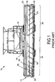
- FIG. 1 illustrates a conventional agricultural harvester 10 such as a combine.
- Harvester 10 includes a header 12 which is attached to a forward end 14 of the harvester and which is configured to cut crops and to induct the cut crops into a feederhouse 16 as harvester 10 moves forward over a crop field.
- Header 12 includes a floor 18 that is supported in desired proximity to the surface of a crop field and an elongate sickle assembly 20 that extends transversely along a forward edge of the floor 18 i.e., in a widthwise direction of the harvester.
- Sickle assembly 20 is configured to cut crops in preparation for induction into the feederhouse 16.
- header 12 includes an elongate, transversely extending harvesting reel 22 disposed above sickle 20.
- Harvesting reel 22 is rotatable in a direction suitable for facilitating the induction of cut crops into feederhouse 16.
- Header 12 further includes an elongate, rotatable auger 24 which extends in close proximity to a top surface 26 of floor 18.
- Auger 24 is configured to cooperate with harvesting reel 22 in conveying cut crops to feederhouse 16, which is configured to convey the cut crops into harvester 10 for threshing and cleaning. While the foregoing aspect of the subject application is being described with respect to a draper header, the cutter assembly of the subject application can be applied to any other header having use for a knife assembly or sickle section.
- Sickle assembly 20 extends along a forward edge 28 of floor 18, and generally is bounded by a first side edge 30 and an opposing second side edge 32 of floor 18.
- Sickle assembly 20 can be configured to include a first movable knife assembly 34 and a second movable knife assembly 36 (along with an unillustrated stationary knife).
- the mechanisms of such knife assemblies are known in the art and a typical mechanism is disclosed in U.S. Patent No. 8,151,547 .
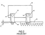
- FIG. 2 there is schematically depicted a conventional sickle knife drive 38 revealing the path of motion imposed by the knife drive on a pair of oppositely directed movable knives or cutter bars.
- the crank shafts and drive gears of sickle knife drive 38 are omitted.
- at least one crank shaft is associated with each movable knife blade or cutter bar. That is, each knife or cutter bar has its own crank shaft where at least two separate crank shafts are required to move the pair of knives.
- the knife drive 38 includes a housing 40 in which first and second members 42 are supported for pivoting motion at pivot points 44.
- each member 42 is operably driven by an unillustrated crank shaft and a second end of each member 42 is connected to a movable knife 46 (only one of which is shown in FIG. 2 ).
- a movable knife 46 (only one of which is shown in FIG. 2 ).
- each member 42 pivots, it swings its respective movable knife 46 through an arcuate path 48.
- the knives travel not only from side to side (i.e., transverse to the direction of movement of the harvester) but also fore and aft (i.e., in the direction of movement of the harvester).
- the distance the movable knives travel in the fore and aft direction is indicated by reference "X".
- the movable knives 46 By traveling in the fore and aft direction as well as side to side directions, the movable knives 46 introduce fore and aft vibration into the system. Such vibration not only stresses the knives themselves but also exerts detrimental forces on the moving parts of knife drive assembly, e.g., the crank shafts and gears. As will be appreciated, the fore and aft vibration created by the pivoting knives eventually leads to accelerated failure of the knife drive over time.
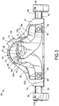
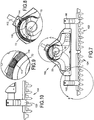
- Knife drive 50 for a cutter assembly of an agricultural header pursuant to an aspect of the subject application.
- the knife drive includes a housing 52 including first and second opposite ends 54, 56 and an opening 58 for receiving a geared input shaft which will be described in greater detail in connection with FIGS. 8 and 9 .
- Knife drive 50 also includes a knife blade or cutter bar drive mechanism 59 for moving the cutter bars or knife blades in simple harmonic motion.
- the drive mechanism 59 includes a crank shaft 60 having first and second opposite ends 62, 64.
- the crank shaft 60 further includes first and second journals 66, 68 that are eccentric with respect to a crank shaft rotation axis 70 (i.e., an eccentric journal) and angularly offset in the manner described in connection with FIG. 6 .
- the first and second journals function as cams as described in detail hereinafter.
- the first journal can be configured as a cylindrical portion 66 located proximate the first end 62 of the crank shaft 60 and the second journal can be configured as a cylindrical portion 68 located adjacent the first cylindrical portion 66.
- the first and second cylindrical portions are angularly offset from each other such as about 90 to 180 degrees.
- the crank shaft further includes a flywheel 72 located adjacent the second journal 68 and coaxial with the crank shaft rotation axis 70 for operatively engaging a driven input gear, as set forth in FIGS. 7-9 .
- the outer cam surfaces of the first and second journal portions 66, 68 furthest from the rotational axis 70 of the crankshaft 60 are angularly offset from each other, and preferably angularly offset by about 90 to 180 degrees, but can alternatively be angularly offset more than 180 or less than 90, such as 100-170 degrees or 80-190 degrees.
- the drive mechanism 59 further includes first and second eccentric sheaves 74, 76 respectively mounted on the first and second journals 66, 68 with eccentric rods or connecting members 78, 80 respectively extending in first and second opposite directions from the first and second eccentric sheaves 74, 76.
- a first or proximal end 78a of the first connecting member is mounted on or otherwise engaged with the first journal 66 and a first or proximal end 80a of the second connecting member is mounted on or otherwise engaged with the second journal 68.
- the second or distal ends 78b, 80b of the first and second connecting members 78, 80 extend in first and second opposite directions toward the first and second opposite ends 54, 56 of housing 52.
- first connecting member 78 is engaged with the first journal 66 and extends in a first direction
- second connecting member 80 is engaged with the second journal 68 and extends in a second direction opposite the first direction such that rotation of the crank shaft 70 produces linear reciprocating motion of the ends of the first and second connecting members.
- the linear reciprocating motion of the end of the first connecting member 78 is in a direction opposite the linear reciprocating motion of the end of the first connecting member 80.
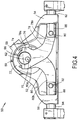
- FIGS. 3 and 4 show a pair of plungers 82, 84 pivotably connected at first ends 86, 88 thereof e.g., via pivots 90, 92 to the second ends 78b, 80b of the eccentric rods or connecting members 78, 80. That is, the first plunger 82 is pivotably connected to the first connecting member 78 and the second plunger 84 is pivotably connected to the second connecting member 80. Second ends 94, 96 of the plungers 82, 84 are connected to first and second sickle knife assemblies. More particularly, the second ends of the plungers may be joined such as by clamping or the like to sickle bar coupler members 98, 100 which respectively are attached to first and second cutter bars or sickle knife blades 102, 104 ( FIGS.
- the first and second eccentric rods or first and second connecting members 78, 80 can be arcuate or curved in shape in order to more effectively convert rotational motion of crank shaft 60 into linear reciprocating or oscillating motion of the plungers 82, 84.
- the plungers 82, 84 are coaxially arranged with each other and are mounted for linear reciprocal or oscillating motion within the first and second opposite ends 54, 56 of housing 52.
- first ends 78a, 80a of the first and second eccentric rods or connecting members 78, 80 include first clamping portions 78c, 80c and second clamping portion 78d, 80d.
- the first claiming portions 78c, 80c cooperatively engage with second clamping portions 78d, 80d e.g., via threaded members 78e, 80e and nuts 78f, 80f ( FIG. 3 ) in order to form the completed eccentric sheaves 74, 76 shown in FIGS. 3 and 4 .
- the second clamping portions 78d, 80d are moved from a first non-clamping position when installing the connecting members 78, 80 to a second clamping position about journals 66, 68 upon completion of installation. That is, the second clamping portions 78d, 80d are moveable relative to the first clamping portions 78c, 80d between first and second positions for clamping of respective first and second journals 66, 68.
- bearings 106 may be mounted within each of the first ends 78a, 80a of the first and second connecting members or eccentric rods 78, 80 between the first clamping portions 78c, 80c and the second clamping portions 78d, 80d.
- crank shaft 60 is converted into linear reciprocating or oscillating motion of the plungers 82, 84.
- This is achieved by the radial and angular offset of the first and second journals 66, 68 situated on crank shaft 60 and their cooperation with the first and second eccentric rods 78, 80.
- FIG. 6 wherein the eccentric rods 78, 80 are omitted for clarity of illustration, the angular and radial offset of the first and second cylindrical portions or journals 66, 68 can be clearly seen.
- FIG. 6 wherein the eccentric rods 78, 80 are omitted for clarity of illustration, the angular and radial offset of the first and second cylindrical portions or journals 66, 68 can be clearly seen.
- first and second journals are radially offset with respect to the crank shaft rotation axis 70 so as to establish first and second cams that cooperatively engage with cam followers defined by the first and second eccentric sheaves 74, 76 shown in FIGS. 3 and 4 .
- the first and second cams are thus eccentrically arranged with respect to the crank shaft.
- the first and second cams can be matingly received within the cam followers in order to minimize vibration and assure smooth transition of rotational crank shaft motion into linear plunger motion.
- the first and second cams are angularly offset from each other about the crank shaft rotation axis. This angular or circumferential offset is indicated by angle " ⁇ " in FIG. 6 .
- the coaxially arranged first and second plungers 82, 84 define a common reciprocation axis 108 which is perpendicular to and spaced from the crank shaft rotation axis 70 by distance "D". Angle ⁇ ranges from about 90 to 180 degrees.
- the cam surfaces of the first and second cams i.e., the first and second eccentric journals 66, 68
- the cam surfaces of the first and second cams can be angularly or circumferentially spaced apart by about 90 to 180 degrees, but can be more or less than 90 or 180 degrees, such as 70, 80, 100, 100, 110, 120, 130, 140, 150, 160, 170, 190, and 200 degrees.
- the cutter assembly 110 includes the center knife drive 50 to which is attached a pair of sickle bar coupler members 98, 100 which, in turn, are connected to a pair of cutter bars or knife blades 102, 104.
- An enlarged view of the connection between sickle bar coupler member 100 and cutter bar 104 is shown in FIG. 10 .
- Cutter bars 102, 104 extend in opposite directions and are arranged in side by side relationship. As will be described below, cutter bars 102, 104 are coaxial and move in opposite directions in a linear reciprocating or oscillating path of motion e.g., the linear oscillation of the first and second cutter bars is simple harmonic motion.
- FIG. 8 shows an enlarged view of a portion of knife drive 50, in particular the drive connection between flywheel 72 and a rotatable input shaft 112 which extends through housing opening 58 ( FIGS. 3-5 ).
- Input shaft 112 may be driven by an unillustrated hydraulic motor or power take off in the manner known in the art.
- the input shaft 112 carries a gear 114 which engages a corresponding gear 116 on flywheel 72.
- flywheel 72 operably engages the driven gear 114 of input shaft 112 to rotate the crank shaft.
- the gears 114, 116 can be cooperating bevel gears. As seen in FIGS.
- the bevel gear 116 on the face of the flywheel is coaxial with the crank shaft rotational axis 70.
- crankshaft 60, and therefore flywheel 72 may be directly driven by the output shaft of a drive motor, i.e., without the need for a geared connection.
- crank shaft rotation may be achieved by a driving connection between input shaft 112 ( FIG. 8 ) and flywheel 72.
- the flywheel 72 and the first and second cylindrical members or journals 66, 68 are likewise caused to rotate.
- first and second eccentric cam surfaces of the first and second journals travel inside and exert motive force i.e., cam against the first and second cam follower surfaces defined by the eccentric sheaves 74, 76.
- This force urges the first ends of the first and second eccentric rods or connecting members 78, 80 to orbit in unison around the crank shaft rotation axis 70.
- the first and second eccentric rods 78, 80 are reciprocatively pulled toward one another ( FIG. 4 ) and pushed away from each other ( FIG. 3 ) in equal and opposite directions in a simple harmonic motion fashion.
- the plungers By being constrained only to linear reciprocating or oscillating motion the plungers transmit such linear motion to the cutter bars such that fore and aft cutter bar motion and corresponding fore and aft vibrations are essentially eliminated. Additionally, by virtue of the second ends of the first and second connecting members moving in equal and opposite directions, lateral vibration is minimized thereby resulting in essentially a vibration-free cutter assembly.
Landscapes
- Life Sciences & Earth Sciences (AREA)
- Environmental Sciences (AREA)
- Zoology (AREA)
- Harvester Elements (AREA)
Claims (12)
- Eine Schneidanordnung (110) für ein Vorsatzgerät (12) einer landwirtschaftlichen Erntemaschine, mit:einem Messerantrieb (50), der Folgendes einschließt:ein Gehäuse (52);einer Kurbelwelle (60) mit einem ersten zylindrischen Teil (66) und einem zweiten zylindrischen Teil (68), der radial gegenüber dem ersten zylindrischen Teil (66) versetzt ist;einer ersten exzentrischen Treibscheibe (74), die auf dem ersten zylindrischen Teil (66) befestigt ist, undeiner ersten exzentrischen Stange (78), die sich von der ersten exzentrischen Treibscheibe (74) aus erstreckt; undeiner zweiten exzentrischen Treibscheibe (76), die auf dem zweiten zylindrischen Teil (68) befestigt ist, und einer zweiten exzentrischen Stange (80), die sich von der zweiten exzentrischen Treibscheibe (76) aus erstreckt;einem ersten Schneidbalken (102), der an einem distalen Ende der ersten exzentrischen Stange (78) angebracht ist; undeinem zweiten Schneidbalken (104), der an einem distalen Ende der zweiten exzentrischen Stange (80) angebracht ist,wobei die ersten und zweiten Schneidbalken (102, 104) Seite an Seite angeordnet sind und wobei eine Drehung der Kurbelwelle (60) eine lineare Schwingung der ersten und zweiten Schneidbalken (102, 104) ergibt, dadurch gekennzeichnet, dass der Messerantrieb (50) weiterhin Folgendes einschließt:erste und zweite Stößel (82, 84), die jeweils erste und zweite Enden aufweisen, wobei der erste Stößel (82) für eine lineare Bewegung an einem ersten Ende des Gehäuses (52) gelagert ist und der zweite Stößel (84) für eine lineare Bewegung an einem zweiten Ende des Gehäuses (52) entgegengesetzt zu dem ersten Ende gelagert ist, wobei der erste Stößel (82) an seinem ersten Ende mit dem zweiten Ende der ersten exzentrischen Stange (78) verbunden ist und sein zweites Ende für einen Anschluss des ersten Schneidbalkens (102) konfiguriert ist, wobei der zweite Stößel (84) an seinem ersten Ende mit dem zweiten Ende der zweiten exzentrischen Stange (80) verbunden ist und sein zweites Ende für einen Anschluss des zweiten Schneidbalkens (104) konfiguriert ist,wobei eine Drehung der Kurbelwelle (60) eine Drehung der ersten und zweiten zylindrischen Teile (66, 68) gegen die ersten und zweiten Treibscheiben (74, 76) und eine lineare Hin- und Herbewegung der ersten und zweiten Stößel (82, 84) in entgegengesetzten Richtungen hervorruft.
- Schneidanordnung (110) nach Anspruch 1, bei der die Kurbelwelle (60) weiterhin ein Schwungrad (72) umfasst, das betriebsmäßig mit einem angetriebenen Zahnrad (114) in Eingriff steht, um die Kurbelwelle (60) in Drehung zu versetzen.
- Die Schneidanordnung (110) nach Anspruch 1, bei der die ersten und zweiten exzentrischen Stangen (78, 80) eine Bogenform aufweisen.
- Die Schneidanordnung (110) nach Anspruch 1, bei der die ersten und zweiten zylindrischen Teile (66, 68) winkelmäßig gegeneinander versetzt sind.
- Die Schneidanordnung (110) nach Anspruch 4, bei der der erste zylindrische Teil (66) gegenüber dem zweiten zylindrischen Teil (68) um ungefähr 90° bis 180° versetzt ist.
- Die Schneidanordnung (110) nach Anspruch 1, bei der die lineare Schwingung der ersten und zweiten Schneidbalken (102, 104) eine einfache harmonische Bewegung ist.
- Die Schneidanordnung (110) nach Anspruch 1, bei der das zweite Ende der ersten exzentrischen Stange (78) sich in einer ersten Richtung erstreckt, und das zweite Ende der zweiten exzentrischen Stange (80) sich in einer zweiten Richtung entgegengesetzt zu der ersten Richtung erstreckt.
- Die Schneidanordnung (110) nach Anspruch 1, bei der die ersten und zweiten Stößel (82, 84) eine gemeinsame Hin- und Herbewegungs-Achse definieren, die unter einem rechten Winkel zu einer Kurbelwellen-Drehachse (70) steht und in Abstand von dieser angeordnet ist.
- Die Schneidanordnung (110) nach Anspruch 1, bei der die ersten und zweiten zylindrischen Teile (66, 68) exzentrisch bezüglich der Kurbelwelle (60) angeordnet sind.
- Die Schneidanordnung (110) nach Anspruch 1, bei der die ersten und zweiten Stößel (82, 84) schwenkbar mit jeweiligen ersten und zweiten exzentrischen Stangen (78, 80) verbunden sind.
- Die Schneidanordnung (110) nach Anspruch 1, bei der jedes der ersten Enden der ersten und zweiten exzentrischen Stangen (78, 80) Folgendes einschließt:einen ersten Klemmteil, undeinen zweiten Klemmteil, der gegenüber dem ersten Klemmteil zwischen ersten und zweiten Positionen beweglich ist, um die jeweiligen ersten und zweiten exzentrischen zylindrischen Teile (66, 68) einzuklemmen.
- Die Schneidanordnung (110) nach Anspruch 1, die weiterhin ein Lager umfasst, das innerhalb jedes der ersten Enden der ersten und zweiten exzentrischen Stangen (78, 80) befestigt sind.
Applications Claiming Priority (1)
| Application Number | Priority Date | Filing Date | Title |
|---|---|---|---|
| US14/107,397 US10721862B2 (en) | 2013-12-16 | 2013-12-16 | Cutter assembly for an agricultural harvester |
Publications (2)
| Publication Number | Publication Date |
|---|---|
| EP2885960A1 EP2885960A1 (de) | 2015-06-24 |
| EP2885960B1 true EP2885960B1 (de) | 2017-05-03 |
Family
ID=52016491
Family Applications (1)
| Application Number | Title | Priority Date | Filing Date |
|---|---|---|---|
| EP14197366.9A Active EP2885960B1 (de) | 2013-12-16 | 2014-12-11 | Schneidanordnung für eine landwirtschaftliche Erntemaschine |
Country Status (4)
| Country | Link |
|---|---|
| US (2) | US10721862B2 (de) |
| EP (1) | EP2885960B1 (de) |
| AU (1) | AU2014274655B2 (de) |
| BR (1) | BR102014031387B8 (de) |
Families Citing this family (20)
| Publication number | Priority date | Publication date | Assignee | Title |
|---|---|---|---|---|
| CN103889206B (zh) | 2011-05-27 | 2017-05-03 | 凯斯纽荷兰(中国)管理有限公司 | 低型面切割器驱动器 |
| US10334781B2 (en) * | 2015-08-20 | 2019-07-02 | Cnh Industrial America Llc | Side shake rate based on machine throughputs |
| DE102015116890A1 (de) * | 2015-10-05 | 2017-04-06 | Carl Geringhoff Gmbh & Co. Kg | Messerantrieb für Schneidwerk zum Anbau an Erntemaschinen |
| DE102016212646A1 (de) * | 2016-07-12 | 2018-01-18 | Deere & Company | Antriebsanordnung zum Antrieb eines Mähwerksbalkens eines Schneidwerks |
| US9924635B1 (en) | 2016-09-28 | 2018-03-27 | Cnh Industrial America Llc | Air blow off cover for synchro-knife drive cleaning |
| US10165726B2 (en) * | 2016-12-23 | 2019-01-01 | Cnh Industrial America Llc | Agricultural header with multiple knife drives |
| US10973169B2 (en) * | 2017-01-10 | 2021-04-13 | Cnh Industrial America Llc | Cutting assembly for a plant cutting machine |
| CN107409621B (zh) * | 2017-03-20 | 2020-03-31 | 中国农业大学 | 一种梳刷振动式枸杞收获试验装置 |
| WO2019010567A1 (en) * | 2017-07-10 | 2019-01-17 | Macdon Industries Ltd. | CENTRAL TRAINING FOR FAUCILLE |
| US10820496B2 (en) | 2017-09-28 | 2020-11-03 | Cnh Industrial America Llc | Center knife drive for an agricultural harvester |
| US10524415B2 (en) * | 2017-10-10 | 2020-01-07 | Cnh Industrial America Llc | Drive arm assembly of a header of an agricultural harvester having an adjustable spherical knife head bearing |
| US10827673B2 (en) * | 2017-12-22 | 2020-11-10 | Cnh Industrial America Llc | Center knife drive for an agricultural harvester |
| US10568259B2 (en) * | 2018-01-09 | 2020-02-25 | Cnh Industrial America Llc | Center link knife drive for a header of an agricultural harvester |
| US10820495B2 (en) * | 2018-06-12 | 2020-11-03 | Cnh Industrial America Llc | Knife drive with integral hydraulic motor for a header of an agricultural harvester |
| JP7253471B2 (ja) * | 2019-08-02 | 2023-04-06 | 株式会社やまびこ | 往復動刈刃装置及び手持ち作業機 |
| DE102020005909A1 (de) * | 2019-10-07 | 2021-04-08 | Makita Corporation | Heckenschere |
| CN112913463A (zh) * | 2019-12-24 | 2021-06-08 | 黄玲 | 猪草收割机 |
| US11343962B2 (en) * | 2020-03-18 | 2022-05-31 | Cnh Industrial America Llc | Mechanical knife drive for a header of an agricultural harvester |
| CN113647242B (zh) * | 2021-09-08 | 2022-12-27 | 青州市沃龙植保机械有限公司 | 一种高地隙单行玉米青储机 |
| JP7695166B2 (ja) * | 2021-09-29 | 2025-06-18 | 株式会社マキタ | 作業機 |
Family Cites Families (48)
| Publication number | Priority date | Publication date | Assignee | Title |
|---|---|---|---|---|
| US384712A (en) * | 1888-06-19 | Willaed l | ||
| US385272A (en) * | 1888-06-26 | johnson | ||
| US129357A (en) * | 1872-07-16 | Improvement in cutting apparatus for harvesters | ||
| US264511A (en) * | 1882-09-19 | Device for converting motion | ||
| US2736156A (en) | 1956-02-28 | hardman | ||
| US105111A (en) * | 1870-07-05 | Improvement in cutting- apparatus for harvesters | ||
| US671024A (en) | 1900-07-30 | 1901-04-02 | Volney J Long | Mower. |
| US738033A (en) * | 1901-11-07 | 1903-09-01 | Alva Thomas Haynes | Mowing-machine. |
| US1017863A (en) * | 1910-12-05 | 1912-02-20 | James B Fulton | Double sickle for mowers and harvesters. |
| US1281825A (en) * | 1916-07-05 | 1918-10-15 | Int Harvester Canada | Cutting apparatus for mowing-machines and harvesters. |
| US1724300A (en) * | 1923-02-05 | 1929-08-13 | Moncreiffe Malcolm | Mower |
| US1647867A (en) | 1925-06-24 | 1927-11-01 | Charles L Fowler | Lawn mower |
| US2156009A (en) | 1937-07-29 | 1939-04-25 | Carando Machine Works | Mower attachment |
| US2157041A (en) * | 1938-01-03 | 1939-05-02 | Detroit Harvester Co | Mowing machine structure |
| US2553523A (en) | 1948-02-02 | 1951-05-15 | Glenn A Wright | Horizontal sickle |
| US2808696A (en) * | 1954-10-26 | 1957-10-08 | Int Harvester Co | Counterbalanced drive mechanism for harvester sickles |
| US3517494A (en) * | 1967-07-11 | 1970-06-30 | Philips Corp | Mowing machines having an eccentric drive |
| US4023334A (en) | 1973-12-26 | 1977-05-17 | Harry Charles Heath | Mowing machine |
| US3897630A (en) * | 1974-04-24 | 1975-08-05 | Black & Decker Mfg Co | Double cam drive for a hedge trimmer having two reciprocating cutting blades |
| DE2444173A1 (de) | 1974-09-16 | 1976-03-25 | Krinke & Krueger Gmbh | Vorrichtung zum antrieb der doppelmesser eines maehwerkes |
| DE2524464A1 (de) * | 1975-06-03 | 1976-12-09 | Busatis Werke Kg | Maehwerkantrieb |
| US4246742A (en) * | 1978-12-11 | 1981-01-27 | Hesston Corporation | Double sickle mechanism |
| IT8221151U1 (it) | 1982-03-16 | 1983-09-16 | Gaspardo Spa | Biellismo in particolare per organi taglianti di falciatrici. |
| US4446683A (en) | 1982-09-29 | 1984-05-08 | Canadian Cooperative Implements Limited | Knife drive |
| IT1205147B (it) * | 1987-06-12 | 1989-03-15 | Bcs Spa | Dispositivo falciante anti-intasamento,dinamicamente compensato |
| DD271010A3 (de) * | 1987-08-14 | 1989-08-23 | Fortschritt Veb K | Messerantrieb fuer feldfutterschneidwerke |
| JPH0545141Y2 (de) * | 1988-03-25 | 1993-11-17 | ||
| US5497605A (en) * | 1994-11-15 | 1996-03-12 | Deere & Company | Header and feeder for a grain combine |
| JPH119089A (ja) * | 1997-06-25 | 1999-01-19 | Kioritz Corp | 手持ち式動力作業機 |
| JP4448569B2 (ja) * | 1999-01-28 | 2010-04-14 | デルタ工業株式会社 | 円運動を往復運動に変換するためのカム構造およびこのカム構造を用いたカム装置並びにこのカム装置を用いた刈込み機 |
| US6314707B1 (en) | 2000-01-06 | 2001-11-13 | Cyril A. Ryan | Balanced reciprocating, brush cutting, mower attachment |
| US6889492B1 (en) * | 2003-11-25 | 2005-05-10 | Cnh America Llc | Reversing transfer drive for sickle cutting knives on a header of an agricultural combine |
| US7757405B2 (en) * | 2006-09-19 | 2010-07-20 | Echo, Incorporated | Trimmer with reciprocating blades |
| JP4958529B2 (ja) * | 2006-12-08 | 2012-06-20 | 株式会社やまびこ | 刈込機 |
| US7401458B2 (en) * | 2006-12-22 | 2008-07-22 | Cnh America Llc | Compact sickle drive for a header of an agricultural plant cutting machine |
| US7520118B1 (en) * | 2007-10-24 | 2009-04-21 | Cnh America Llc | Header with high speed sickle drives for a plant cutting machine |
| US7730709B2 (en) * | 2007-12-06 | 2010-06-08 | Cnh America Llc | Compact epicyclical drive |
| US7805919B2 (en) * | 2007-12-06 | 2010-10-05 | Cnh America Llc | Offset epicyclic sickle drive for a header of an agricultural plant cutting machine |
| DE102008062603A1 (de) * | 2008-12-17 | 2010-10-21 | Andreas Stihl Ag & Co. Kg | Arbeitsgerät |
| US8151547B2 (en) | 2009-10-02 | 2012-04-10 | Cnh America Llc | Blade assembly removal from a header of a plant cutting machine |
| US8011272B1 (en) * | 2010-04-28 | 2011-09-06 | Cnh America Llc | Dual flywheel axially compact epicyclical drive |
| EP2713695B1 (de) * | 2011-05-27 | 2016-08-24 | CNH Industrial Belgium nv | Nockengetriebener niedrigprofil-reckschwingenantrieb |
| WO2012166675A1 (en) * | 2011-05-27 | 2012-12-06 | Cnh America Llc | Slot driven low profile sickle drive |
| CN103889206B (zh) * | 2011-05-27 | 2017-05-03 | 凯斯纽荷兰(中国)管理有限公司 | 低型面切割器驱动器 |
| WO2012166666A1 (en) * | 2011-05-27 | 2012-12-06 | Cnh America Llc | Pivoting knife arm assembly for a sickle |
| CN103987247B (zh) | 2011-06-16 | 2018-01-09 | 凯斯纽荷兰(中国)管理有限公司 | 用于植物切割机器的切割器的中心刀驱动器的底板密封件 |
| DE202011106656U1 (de) | 2011-10-12 | 2011-12-01 | August Kuhlenkamp | Mähwerksvorrichtung |
| US8973345B2 (en) * | 2013-02-05 | 2015-03-10 | Deere & Company | Drive assembly for an agricultural harvesting platform |
-
2013
- 2013-12-16 US US14/107,397 patent/US10721862B2/en active Active
-
2014
- 2014-12-11 EP EP14197366.9A patent/EP2885960B1/de active Active
- 2014-12-15 AU AU2014274655A patent/AU2014274655B2/en active Active
- 2014-12-15 BR BR102014031387A patent/BR102014031387B8/pt not_active IP Right Cessation
-
2020
- 2020-06-23 US US16/908,839 patent/US11224161B2/en active Active
Also Published As
| Publication number | Publication date |
|---|---|
| AU2014274655A1 (en) | 2015-07-02 |
| US20150163994A1 (en) | 2015-06-18 |
| AU2014274655B2 (en) | 2017-06-15 |
| US20200315088A1 (en) | 2020-10-08 |
| EP2885960A1 (de) | 2015-06-24 |
| US10721862B2 (en) | 2020-07-28 |
| BR102014031387B1 (pt) | 2020-07-14 |
| BR102014031387B8 (pt) | 2020-11-10 |
| US11224161B2 (en) | 2022-01-18 |
| BR102014031387A2 (pt) | 2017-07-25 |
Similar Documents
| Publication | Publication Date | Title |
|---|---|---|
| US11224161B2 (en) | Cutter assembly for an agricultural harvester | |
| EP2382852B1 (de) | Axial kompaktes Zweimassenschwungrad mit epizyklischem Getriebe | |
| EP2713691B1 (de) | Niedrigprofil-sichelantrieb mit schwenkwirkung | |
| US6889492B1 (en) | Reversing transfer drive for sickle cutting knives on a header of an agricultural combine | |
| EP2713692B1 (de) | Niedrigprofil-reckschwingenantrieb | |
| EP3501256B1 (de) | Mittelmesserantrieb für eine landwirtschaftliche erntemaschine | |
| US6314707B1 (en) | Balanced reciprocating, brush cutting, mower attachment | |
| EP2713693B1 (de) | Niedrigprofil-mähbalkenantrieb mit langlochführung | |
| US10531608B2 (en) | Knife drive assembly for an agricultural harvester | |
| JP2581170Y2 (ja) | 往復鋸刃装置 | |
| US10602661B2 (en) | Mowing cutter drive | |
| EP3616493B1 (de) | Erntemaschinenschneidwerkmesserantrieb mit zylindrischem nocken oder selbstumdrehendem leitspindelmechanismus | |
| US5373641A (en) | Reciprocating cutter type trimmer | |
| EP3476197B1 (de) | Vorsatz für eine landwirtschaftliche erntemaschine mit einem zuführförderer, der mit einem mittelmesserantrieb verbunden ist | |
| US4860528A (en) | Reciprocating conditioning rolls | |
| US10356976B2 (en) | Drive arrangement for driving a cutter bar of a cutting mechanism | |
| CN209572448U (zh) | 双动刀往复式切割器 | |
| EP3476196B1 (de) | Mittelmesserantriebs- und -rollenanordnung für eine landwirtschaftliche erntemaschine | |
| US4922692A (en) | Method of conditioning forage crops | |
| JP2588747Y2 (ja) | バリカン形刈払機 | |
| JPH03112409A (ja) | コンバイン等の刈刃装置 | |
| RU2588163C2 (ru) | Низкопрофильный привод режущего аппарата поворотного действия |
Legal Events
| Date | Code | Title | Description |
|---|---|---|---|
| PUAI | Public reference made under article 153(3) epc to a published international application that has entered the european phase |
Free format text: ORIGINAL CODE: 0009012 |
|
| 17P | Request for examination filed |
Effective date: 20141211 |
|
| AK | Designated contracting states |
Kind code of ref document: A1 Designated state(s): AL AT BE BG CH CY CZ DE DK EE ES FI FR GB GR HR HU IE IS IT LI LT LU LV MC MK MT NL NO PL PT RO RS SE SI SK SM TR |
|
| AX | Request for extension of the european patent |
Extension state: BA ME |
|
| R17P | Request for examination filed (corrected) |
Effective date: 20160104 |
|
| RBV | Designated contracting states (corrected) |
Designated state(s): AL AT BE BG CH CY CZ DE DK EE ES FI FR GB GR HR HU IE IS IT LI LT LU LV MC MK MT NL NO PL PT RO RS SE SI SK SM TR |
|
| GRAP | Despatch of communication of intention to grant a patent |
Free format text: ORIGINAL CODE: EPIDOSNIGR1 |
|
| STAA | Information on the status of an ep patent application or granted ep patent |
Free format text: STATUS: GRANT OF PATENT IS INTENDED |
|
| INTG | Intention to grant announced |
Effective date: 20161201 |
|
| GRAS | Grant fee paid |
Free format text: ORIGINAL CODE: EPIDOSNIGR3 |
|
| GRAA | (expected) grant |
Free format text: ORIGINAL CODE: 0009210 |
|
| STAA | Information on the status of an ep patent application or granted ep patent |
Free format text: STATUS: THE PATENT HAS BEEN GRANTED |
|
| AK | Designated contracting states |
Kind code of ref document: B1 Designated state(s): AL AT BE BG CH CY CZ DE DK EE ES FI FR GB GR HR HU IE IS IT LI LT LU LV MC MK MT NL NO PL PT RO RS SE SI SK SM TR |
|
| REG | Reference to a national code |
Ref country code: GB Ref legal event code: FG4D |
|
| REG | Reference to a national code |
Ref country code: AT Ref legal event code: REF Ref document number: 888908 Country of ref document: AT Kind code of ref document: T Effective date: 20170515 Ref country code: CH Ref legal event code: EP |
|
| REG | Reference to a national code |
Ref country code: IE Ref legal event code: FG4D |
|
| REG | Reference to a national code |
Ref country code: DE Ref legal event code: R096 Ref document number: 602014009255 Country of ref document: DE |
|
| REG | Reference to a national code |
Ref country code: NL Ref legal event code: MP Effective date: 20170503 |
|
| REG | Reference to a national code |
Ref country code: AT Ref legal event code: MK05 Ref document number: 888908 Country of ref document: AT Kind code of ref document: T Effective date: 20170503 |
|
| REG | Reference to a national code |
Ref country code: LT Ref legal event code: MG4D |
|
| REG | Reference to a national code |
Ref country code: FR Ref legal event code: PLFP Year of fee payment: 4 |
|
| PG25 | Lapsed in a contracting state [announced via postgrant information from national office to epo] |
Ref country code: GR Free format text: LAPSE BECAUSE OF FAILURE TO SUBMIT A TRANSLATION OF THE DESCRIPTION OR TO PAY THE FEE WITHIN THE PRESCRIBED TIME-LIMIT Effective date: 20170804 Ref country code: FI Free format text: LAPSE BECAUSE OF FAILURE TO SUBMIT A TRANSLATION OF THE DESCRIPTION OR TO PAY THE FEE WITHIN THE PRESCRIBED TIME-LIMIT Effective date: 20170503 Ref country code: NO Free format text: LAPSE BECAUSE OF FAILURE TO SUBMIT A TRANSLATION OF THE DESCRIPTION OR TO PAY THE FEE WITHIN THE PRESCRIBED TIME-LIMIT Effective date: 20170803 Ref country code: HR Free format text: LAPSE BECAUSE OF FAILURE TO SUBMIT A TRANSLATION OF THE DESCRIPTION OR TO PAY THE FEE WITHIN THE PRESCRIBED TIME-LIMIT Effective date: 20170503 Ref country code: LT Free format text: LAPSE BECAUSE OF FAILURE TO SUBMIT A TRANSLATION OF THE DESCRIPTION OR TO PAY THE FEE WITHIN THE PRESCRIBED TIME-LIMIT Effective date: 20170503 Ref country code: ES Free format text: LAPSE BECAUSE OF FAILURE TO SUBMIT A TRANSLATION OF THE DESCRIPTION OR TO PAY THE FEE WITHIN THE PRESCRIBED TIME-LIMIT Effective date: 20170503 Ref country code: AT Free format text: LAPSE BECAUSE OF FAILURE TO SUBMIT A TRANSLATION OF THE DESCRIPTION OR TO PAY THE FEE WITHIN THE PRESCRIBED TIME-LIMIT Effective date: 20170503 |
|
| PG25 | Lapsed in a contracting state [announced via postgrant information from national office to epo] |
Ref country code: NL Free format text: LAPSE BECAUSE OF FAILURE TO SUBMIT A TRANSLATION OF THE DESCRIPTION OR TO PAY THE FEE WITHIN THE PRESCRIBED TIME-LIMIT Effective date: 20170503 Ref country code: IS Free format text: LAPSE BECAUSE OF FAILURE TO SUBMIT A TRANSLATION OF THE DESCRIPTION OR TO PAY THE FEE WITHIN THE PRESCRIBED TIME-LIMIT Effective date: 20170903 Ref country code: BG Free format text: LAPSE BECAUSE OF FAILURE TO SUBMIT A TRANSLATION OF THE DESCRIPTION OR TO PAY THE FEE WITHIN THE PRESCRIBED TIME-LIMIT Effective date: 20170803 Ref country code: LV Free format text: LAPSE BECAUSE OF FAILURE TO SUBMIT A TRANSLATION OF THE DESCRIPTION OR TO PAY THE FEE WITHIN THE PRESCRIBED TIME-LIMIT Effective date: 20170503 Ref country code: PL Free format text: LAPSE BECAUSE OF FAILURE TO SUBMIT A TRANSLATION OF THE DESCRIPTION OR TO PAY THE FEE WITHIN THE PRESCRIBED TIME-LIMIT Effective date: 20170503 Ref country code: RS Free format text: LAPSE BECAUSE OF FAILURE TO SUBMIT A TRANSLATION OF THE DESCRIPTION OR TO PAY THE FEE WITHIN THE PRESCRIBED TIME-LIMIT Effective date: 20170503 Ref country code: SE Free format text: LAPSE BECAUSE OF FAILURE TO SUBMIT A TRANSLATION OF THE DESCRIPTION OR TO PAY THE FEE WITHIN THE PRESCRIBED TIME-LIMIT Effective date: 20170503 |
|
| PG25 | Lapsed in a contracting state [announced via postgrant information from national office to epo] |
Ref country code: DK Free format text: LAPSE BECAUSE OF FAILURE TO SUBMIT A TRANSLATION OF THE DESCRIPTION OR TO PAY THE FEE WITHIN THE PRESCRIBED TIME-LIMIT Effective date: 20170503 Ref country code: CZ Free format text: LAPSE BECAUSE OF FAILURE TO SUBMIT A TRANSLATION OF THE DESCRIPTION OR TO PAY THE FEE WITHIN THE PRESCRIBED TIME-LIMIT Effective date: 20170503 Ref country code: RO Free format text: LAPSE BECAUSE OF FAILURE TO SUBMIT A TRANSLATION OF THE DESCRIPTION OR TO PAY THE FEE WITHIN THE PRESCRIBED TIME-LIMIT Effective date: 20170503 Ref country code: SK Free format text: LAPSE BECAUSE OF FAILURE TO SUBMIT A TRANSLATION OF THE DESCRIPTION OR TO PAY THE FEE WITHIN THE PRESCRIBED TIME-LIMIT Effective date: 20170503 Ref country code: EE Free format text: LAPSE BECAUSE OF FAILURE TO SUBMIT A TRANSLATION OF THE DESCRIPTION OR TO PAY THE FEE WITHIN THE PRESCRIBED TIME-LIMIT Effective date: 20170503 |
|
| REG | Reference to a national code |
Ref country code: DE Ref legal event code: R097 Ref document number: 602014009255 Country of ref document: DE |
|
| PG25 | Lapsed in a contracting state [announced via postgrant information from national office to epo] |
Ref country code: SM Free format text: LAPSE BECAUSE OF FAILURE TO SUBMIT A TRANSLATION OF THE DESCRIPTION OR TO PAY THE FEE WITHIN THE PRESCRIBED TIME-LIMIT Effective date: 20170503 |
|
| PLBE | No opposition filed within time limit |
Free format text: ORIGINAL CODE: 0009261 |
|
| STAA | Information on the status of an ep patent application or granted ep patent |
Free format text: STATUS: NO OPPOSITION FILED WITHIN TIME LIMIT |
|
| 26N | No opposition filed |
Effective date: 20180206 |
|
| PG25 | Lapsed in a contracting state [announced via postgrant information from national office to epo] |
Ref country code: SI Free format text: LAPSE BECAUSE OF FAILURE TO SUBMIT A TRANSLATION OF THE DESCRIPTION OR TO PAY THE FEE WITHIN THE PRESCRIBED TIME-LIMIT Effective date: 20170503 |
|
| REG | Reference to a national code |
Ref country code: CH Ref legal event code: PL |
|
| REG | Reference to a national code |
Ref country code: IE Ref legal event code: MM4A |
|
| PG25 | Lapsed in a contracting state [announced via postgrant information from national office to epo] |
Ref country code: LU Free format text: LAPSE BECAUSE OF NON-PAYMENT OF DUE FEES Effective date: 20171211 Ref country code: MT Free format text: LAPSE BECAUSE OF NON-PAYMENT OF DUE FEES Effective date: 20171211 |
|
| REG | Reference to a national code |
Ref country code: FR Ref legal event code: PLFP Year of fee payment: 5 Ref country code: BE Ref legal event code: MM Effective date: 20171231 |
|
| PG25 | Lapsed in a contracting state [announced via postgrant information from national office to epo] |
Ref country code: IE Free format text: LAPSE BECAUSE OF NON-PAYMENT OF DUE FEES Effective date: 20171211 |
|
| PG25 | Lapsed in a contracting state [announced via postgrant information from national office to epo] |
Ref country code: BE Free format text: LAPSE BECAUSE OF NON-PAYMENT OF DUE FEES Effective date: 20171231 Ref country code: CH Free format text: LAPSE BECAUSE OF NON-PAYMENT OF DUE FEES Effective date: 20171231 Ref country code: LI Free format text: LAPSE BECAUSE OF NON-PAYMENT OF DUE FEES Effective date: 20171231 |
|
| PG25 | Lapsed in a contracting state [announced via postgrant information from national office to epo] |
Ref country code: HU Free format text: LAPSE BECAUSE OF FAILURE TO SUBMIT A TRANSLATION OF THE DESCRIPTION OR TO PAY THE FEE WITHIN THE PRESCRIBED TIME-LIMIT; INVALID AB INITIO Effective date: 20141211 Ref country code: MC Free format text: LAPSE BECAUSE OF FAILURE TO SUBMIT A TRANSLATION OF THE DESCRIPTION OR TO PAY THE FEE WITHIN THE PRESCRIBED TIME-LIMIT Effective date: 20170503 |
|
| PG25 | Lapsed in a contracting state [announced via postgrant information from national office to epo] |
Ref country code: CY Free format text: LAPSE BECAUSE OF FAILURE TO SUBMIT A TRANSLATION OF THE DESCRIPTION OR TO PAY THE FEE WITHIN THE PRESCRIBED TIME-LIMIT Effective date: 20170503 |
|
| PG25 | Lapsed in a contracting state [announced via postgrant information from national office to epo] |
Ref country code: MK Free format text: LAPSE BECAUSE OF FAILURE TO SUBMIT A TRANSLATION OF THE DESCRIPTION OR TO PAY THE FEE WITHIN THE PRESCRIBED TIME-LIMIT Effective date: 20170503 |
|
| PG25 | Lapsed in a contracting state [announced via postgrant information from national office to epo] |
Ref country code: TR Free format text: LAPSE BECAUSE OF FAILURE TO SUBMIT A TRANSLATION OF THE DESCRIPTION OR TO PAY THE FEE WITHIN THE PRESCRIBED TIME-LIMIT Effective date: 20170503 |
|
| PG25 | Lapsed in a contracting state [announced via postgrant information from national office to epo] |
Ref country code: PT Free format text: LAPSE BECAUSE OF FAILURE TO SUBMIT A TRANSLATION OF THE DESCRIPTION OR TO PAY THE FEE WITHIN THE PRESCRIBED TIME-LIMIT Effective date: 20170503 |
|
| REG | Reference to a national code |
Ref country code: DE Ref legal event code: R082 Ref document number: 602014009255 Country of ref document: DE Representative=s name: MEISSNER BOLTE PATENTANWAELTE RECHTSANWAELTE P, DE |
|
| PG25 | Lapsed in a contracting state [announced via postgrant information from national office to epo] |
Ref country code: AL Free format text: LAPSE BECAUSE OF FAILURE TO SUBMIT A TRANSLATION OF THE DESCRIPTION OR TO PAY THE FEE WITHIN THE PRESCRIBED TIME-LIMIT Effective date: 20170503 |
|
| PGFP | Annual fee paid to national office [announced via postgrant information from national office to epo] |
Ref country code: GB Payment date: 20231218 Year of fee payment: 10 |
|
| PGFP | Annual fee paid to national office [announced via postgrant information from national office to epo] |
Ref country code: IT Payment date: 20231127 Year of fee payment: 10 |
|
| PGFP | Annual fee paid to national office [announced via postgrant information from national office to epo] |
Ref country code: DE Payment date: 20241227 Year of fee payment: 11 |
|
| GBPC | Gb: european patent ceased through non-payment of renewal fee |
Effective date: 20241211 |
|
| PG25 | Lapsed in a contracting state [announced via postgrant information from national office to epo] |
Ref country code: IT Free format text: LAPSE BECAUSE OF NON-PAYMENT OF DUE FEES Effective date: 20241211 |
|
| PG25 | Lapsed in a contracting state [announced via postgrant information from national office to epo] |
Ref country code: GB Free format text: LAPSE BECAUSE OF NON-PAYMENT OF DUE FEES Effective date: 20241211 |
|
| PGFP | Annual fee paid to national office [announced via postgrant information from national office to epo] |
Ref country code: FR Payment date: 20251223 Year of fee payment: 12 |