EP2885148B1 - Fahrzeugkraftstoffzubehör - Google Patents
Fahrzeugkraftstoffzubehör Download PDFInfo
- Publication number
- EP2885148B1 EP2885148B1 EP13762284.1A EP13762284A EP2885148B1 EP 2885148 B1 EP2885148 B1 EP 2885148B1 EP 13762284 A EP13762284 A EP 13762284A EP 2885148 B1 EP2885148 B1 EP 2885148B1
- Authority
- EP
- European Patent Office
- Prior art keywords
- port
- confined space
- fluid
- housing
- liquid
- Prior art date
- Legal status (The legal status is an assumption and is not a legal conclusion. Google has not performed a legal analysis and makes no representation as to the accuracy of the status listed.)
- Active
Links
Images





Classifications
-
- F—MECHANICAL ENGINEERING; LIGHTING; HEATING; WEAPONS; BLASTING
- F02—COMBUSTION ENGINES; HOT-GAS OR COMBUSTION-PRODUCT ENGINE PLANTS
- F02M—SUPPLYING COMBUSTION ENGINES IN GENERAL WITH COMBUSTIBLE MIXTURES OR CONSTITUENTS THEREOF
- F02M25/00—Engine-pertinent apparatus for adding non-fuel substances or small quantities of secondary fuel to combustion-air, main fuel or fuel-air mixture
- F02M25/08—Engine-pertinent apparatus for adding non-fuel substances or small quantities of secondary fuel to combustion-air, main fuel or fuel-air mixture adding fuel vapours drawn from engine fuel reservoir
-
- B—PERFORMING OPERATIONS; TRANSPORTING
- B60—VEHICLES IN GENERAL
- B60K—ARRANGEMENT OR MOUNTING OF PROPULSION UNITS OR OF TRANSMISSIONS IN VEHICLES; ARRANGEMENT OR MOUNTING OF PLURAL DIVERSE PRIME-MOVERS IN VEHICLES; AUXILIARY DRIVES FOR VEHICLES; INSTRUMENTATION OR DASHBOARDS FOR VEHICLES; ARRANGEMENTS IN CONNECTION WITH COOLING, AIR INTAKE, GAS EXHAUST OR FUEL SUPPLY OF PROPULSION UNITS IN VEHICLES
- B60K15/00—Arrangement in connection with fuel supply of combustion engines or other fuel consuming energy converters, e.g. fuel cells; Mounting or construction of fuel tanks
- B60K15/03—Fuel tanks
- B60K15/035—Fuel tanks characterised by venting means
-
- B—PERFORMING OPERATIONS; TRANSPORTING
- B60—VEHICLES IN GENERAL
- B60K—ARRANGEMENT OR MOUNTING OF PROPULSION UNITS OR OF TRANSMISSIONS IN VEHICLES; ARRANGEMENT OR MOUNTING OF PLURAL DIVERSE PRIME-MOVERS IN VEHICLES; AUXILIARY DRIVES FOR VEHICLES; INSTRUMENTATION OR DASHBOARDS FOR VEHICLES; ARRANGEMENTS IN CONNECTION WITH COOLING, AIR INTAKE, GAS EXHAUST OR FUEL SUPPLY OF PROPULSION UNITS IN VEHICLES
- B60K15/00—Arrangement in connection with fuel supply of combustion engines or other fuel consuming energy converters, e.g. fuel cells; Mounting or construction of fuel tanks
- B60K15/03—Fuel tanks
- B60K15/035—Fuel tanks characterised by venting means
- B60K15/03504—Fuel tanks characterised by venting means adapted to avoid loss of fuel or fuel vapour, e.g. with vapour recovery systems
- B60K2015/03509—Fuel tanks characterised by venting means adapted to avoid loss of fuel or fuel vapour, e.g. with vapour recovery systems with a droplet separator in the vent line
Definitions
- the present disclosed subject matter is concerned with vehicle fuel accessories. More particularly the disclosed subject matter is directed to a vehicle fuel system comprising a fuel tank configured with a fuel accessory and a fuel vapor treating device.
- a liquid vapor separator for example as disclosed in US 6,405,747 directed to an apparatus for controlling discharge of fuel vapor from within a vehicle fuel tank, which apparatus includes at least a primary and auxiliary liquid separating chamber positioned above a float chamber below a valve outlet.
- the apparatus includes at least one baffle arranged to intercept and direct filtered fuel droplets from the vapor flow and return the liquid fuel to the fuel tank.
- the primary and auxiliary liquid separation chambers and associated baffle are positioned to facilitate flow of fuel vapor from the tank yet return liquid fuel to the tank.
- expansion tanks for example as discussed in US 6,318,398 to the applicant of the present application, which discloses a fuel expansion device for a vehicle fuel tank, the device comprising a housing formed of a first housing member and a second housing member, both made of an essentially impermeable material and being sealingly and impermeably attached to one another. At least one inlet port for fuel fluid ingress is formed in the first member and is in flow communication with the fuel tank, and an outlet port is formed in the second member connectable to a fuel fluid handling device.
- US7,694,665 discloses a liquid vapor separator for a vehicle's fuel system, said liquid vapor separator comprising a body having an inlet connectable with a venting system of a fuel tank and a vapor outlet connectable to a fuel vapor treating device, and a condensation space for condensation of fuel droplets, said space being in flow communication with said inlet and with said outlet, and said condensation space extending at or being in flow communication with a filler neck of the fuel system.
- JP S55 119954 A discloses a vehicle fuel accessory.
- it relates to a fuel vapor separation device for separating fuel vapor from liquid fuel.
- No fuel vapor treating device is disclosed.
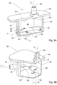
- FIG. 1 Attention is first directed to figures 1 to 3B of the drawings, directed to a first aspect of the present disclosed subject matter, being a fuel liquid trap and generally designated 20.
- the liquid trap 20 comprises a housing generally designated 22 with a base 24, a continuous side wall 28 extending therefrom and a top 30, defining together a confined space designated 38.
- the fuel accessory is a liquid separator 20, it is thus configured for fitting within a vehicle's fuel tank (not shown), and it is further noted that in the present illustrated example the top 30 constitutes a top wall portion 36 of a fuel tank.
- the top can just as well be an independent wall member extending from the side walls of the housing 22, and thus the housing is configured for articulation within the fuel tank as a unitary item, i.e. not integrated with a top wall of the fuel tank, but rather attached thereto.
- the base 24, side wall 28 and top 30 define together a fluid-tight confined space 38 ( Figs. 3A and 3B ) with a liquid inlet port 40 extending into the confined space 38 at a curved side wall portion 42.
- the liquid inlet port 40 extends substantially tangent to the side wall 28 and a flow path through the liquid inlet port merges with the wall portion 42 such that the flow path is minimally interrupted as it enters the confined space 38, and whereby fluid ingressing through the inlet port 40 is caused to swirl about the inside surface 46 of the side walls 28, as represented by arrowed line 50, thus imparting the ingressing fluid a cyclonical flow pattern along the inside 46 surface of the side walls 28.
- the side walls of the housing may be circular or comprise at least one or more arced wall portions, which result in imparting the fluid ingressing through the inlet port 40 to swirl about the inside surface 46 of the side walls, as mentioned hereinabove.
- the construction of the housing and the inlet port can be configured to allow a cyclonic separation or the fuel fluid flow such that the fuel liquid drops are separated from the fuel vapor through vortex separation.
- the gravity and rotational effects caused by the inlet port extending tangentially to a rounded wall portion facilitate the separation of the fuel droplets and the fuel vapor.
- the wall portion 42 in which the inlet port merges need not be the wall portion of the housing, rather can be a wall portion which is inserted inside the confined space for the purpose of allowing the fluid ingressing through the inlet to engage it and to thereby cause a rotational effect thereof, and the cyclone separation of the fuel droplets.
- the housing 22 is further configured at the top 30 with a fluid outlet port 60, configured for coupling to a fuel vapor treating device (not shown), such as a canister, an expansion tank, and the like.
- a fuel vapor treating device such as a canister, an expansion tank, and the like.
- the fluid outlet port 60 is in turn is configured with an inlet opening 62 in the form of an annular extension extending downwards from a bottom surface 33 of the top 30 of the housing 22 and extending remote from the side walls 28 (and from the bottom surface 33 of the top 30, owing to said annular extension 62 ).
- This arrangement ensures that fluid egressing through the fluid outlet port 60 substantially does not drift along with it liquid droplets.
- a longitudinal axis X of the fluid outlet port 60 extends substantially parallel to the side walls 28 and normal to the top 30, and further substantially normal to the longitudinal axis T of the substantially tangentially extending fluid inlet port 40.
- the housing 28 is configured at the base wall 24 with a liquid drain port 70 for draining any liquids striking the inside surface 46 of the side walls 28, and thereby falling to the bottom of the housing.
- the liquid drain port is typically configured at a lowermost location of the base wall 24, wherein a longitudinal axis Y of said liquid drain port extends substantially parallel to the longitudinal axis X of the fluid outlet port 60, this however being a particular example only.
- the liquid drain port 70 is configured with a valve 74 (only partially seen in Fig. 2A ) facilitating fluid flow therethrough only in one direction so as to drain fluid from the confined space 38 and to prevent fluid ingress therethrough.
- the valve 74 can be of any type, setting as an example only an inverted mushroom-type valve, a spring biased membrane, any type of valve-governed valve, e.g. a rollover valve, etc.
- the valve can be an active valve member, e.g. an active pump valve.
- the confined space 38 is substantially homogeneous, i.e. devoid of condensation elements such as walls and ribs, whereby condensation takes place substantially over the inside surface 46 of the side walls 28 of the confined space 38.
- fluid vapor flows into the confined space 38 through the inlet port 40, and is imparted a cyclonical flow pattern along the inside surface 46 of the side walls 28, resulting in increasing liquid condensation over the inside surface 46, whereby any fuel liquid droplets drain along the side walls towards the base 24 and then drain out through the liquid drain port 70, and where fuel fluid in gas state is free to egress thorough the fluid outlet port 60, substantially without any liquid droplets.
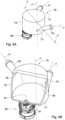
- the housing 77 has a substantially round (circular) side wall 78. Further noted is the fluid inlet port 79 at a lower portion thereof, i.e. near a bottom wall 81 thereof, and further, a longitudinal axis T of the inlet port 79 extends substantially tangentially into the confined space 80 of the housing 77.
- outlet port 82 extends from a top portion of the side wall 78, however wherein the inlet opening of the outlet port 82 extends not near the inlet port 79, and such that an axis X' of the outlet port does not coextend with the axis T of the inlet port 79.
- the inlet port 79 and the outlet port 82 extend substantially normal to a longitudinal axis Y' of the housing 72. Evenmore so, it is noted that the opening of the outlet port 82 is configured with an annular extension 83 extending inwardly from the side wall 78. The above arrangements eliminate or substantially reduce likelihood of fuel droplets escaping through the liquid trap 76 into the outlet port 82.
- liquid trap 76 is configured at a bottom thereof with a float governed valve 86 (setting as an example only, a rollover valve) being in flow communication with a liquid drain port 87 configured at a lower portion of the housing 77 and being in flow communication with the confined space 80.
- a float governed valve 86 (setting as an example only, a rollover valve) being in flow communication with a liquid drain port 87 configured at a lower portion of the housing 77 and being in flow communication with the confined space 80.
- FIG. 1 a liquid vapor separator
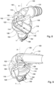
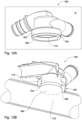
- the liquid vapor separator 100 comprises a housing generally designated 102 with a base portion 104, a tubular (circular) side wall 108 extending therefrom and a top 110, defining together a confined space designated 114.
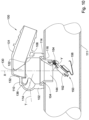
- the fuel accessory is a liquid vapor separator 100, it is thus configured for fitting on a filler neck 111 ('filler pipe'; a schematic portion illustrated for sake of example in Fig. 10 ), of a vehicle's fuel tank (not shown).
- the liquid vapor separator 100 is thus configured with a flange 114 extending from the housing 102, for sealingly welding within an opening 116 of the pipe section 111, or otherwise attaching thereto.
- the base portion 104, side wall 108 and top 110 define together a fluid-tight confined space 114 ( Figs. 8 to 11 ) configured with a liquid inlet port 118 extending into the confined space 114 at the tubular side wall 108.
- the liquid inlet port 118 extends substantially tangent to the side wall 108 and a flow path through the liquid inlet port merges with the side wall portion 108, such that the flow path is minimally interrupted as it enters the confined space 114, and whereby fluid ingressing through the inlet port 118 is caused to swirl about the inside surface 122 of the side wall 108, as represented by arrowed line 128, thus imparting the ingressing fluid a cyclonical flow pattern along the inside surface 122 of the side wall 108.
- the side walls of the housing may be circular or comprise at least one or more arced wall portions, which result in imparting the fluid ingressing through the inlet port 118 to swirl about the inside surface 122 of the side walls 108, as mentioned hereinabove.
- the housing 102 is further configured at the top 110 with a fluid outlet port 130, configured for coupling to a fuel vapor treating device (not shown), such as a canister, and the like.
- a fuel vapor treating device such as a canister, and the like.
- the fluid outlet port 130 is in turn is configured with a coupling pipe extension 131 and an inlet opening 132 in the form of an annular extension extending downwards from a bottom surface 136 of the top 110 of the housing 102 and extending remote from the side walls 108 (and from the bottom surface 136 of the top 110, owing to said annular extension 132 ).
- This arrangement ensures that fluid egressing through the fluid outlet port 130 substantially does not drift along with it liquid droplets.
- a longitudinal axis X of the fluid outlet port 130 extends substantially parallel to the side walls 108 and normal to the top 110, and further substantially normal to the longitudinal axis T of the substantially tangentially extending fluid inlet port 118.
- the housing 102 is configured at the base wall 104 with a liquid drain port 144 for draining any liquids engaging the inside surface 122 of the side walls 108, said liquid drain port 144 configured at a lowermost location of the base wall 108, wherein a longitudinal axis Y of said liquid drain port 144 extends substantially coaxial with the longitudinal axis X of the fluid outlet port 130, this however being a particular example only.
- the liquid drain port 144 is configured with a normally open shutoff gate assembly generally designated 150, comprising a sealing gate 152 pivotally articulated at 154 to the liquid drain port 144 and fitted with a filler spout engaging lever 156, which is configured for pivotal displacement into a closed position upon introducing a filler spout ('filler gun'; not shown) into the filler pipe 111, to thereby prevent liquid fuel and fuel vapor flow into the liquid vapor separator 100 during a fueling process.
- a filler spout 'filler gun'; not shown
- facilitating fluid flow is facilitated through the liquid drain port 144 in direction so as to drain fluid from the confined space 114.
- the confined space 114 is substantially homogeneous, i.e. devoid of condensation elements such as walls and ribs, whereby condensation takes place substantially over the inside surface 122 of the side walls 108 of the confined space 114.
- fluid vapor flows into the confined space 114 through the inlet port 118, and is imparted a cyclonical flow pattern along the inside surface 122 of the side walls 108 (illustrated by arrowed flow path 128 ), resulting in increasing liquid condensation over the inside surface 122, whereby any fuel liquid droplets drain along the side walls towards the base 104 and then drain out through the liquid drain port 144 and into the filler neck 111, and where fuel fluid in gas state is free to egress thorough the fluid outlet port 130 and further through coupling pipe extension 131, substantially without any liquid droplets.
- the housing 162 has a base 164 terminating at an annular seat 166 configured for mounting over a respective opening 168 of a filler pipe 170 of a fuel tank (not shown), devoid of a shutoff gate assembly as presented in the example of figures 5 to 11 .
- liquid vapor separator 160 is substantially similar to liquid vapor separator 100, whereby fuel droplets generated over the inside surface 174 of the side wall 176 of the housing 162 is free to drip directly into the filler pipe 170 through opening 168.
- the housing can be formed without a collecting space for collecting the fuel, rather the filler head serves as a collecting space for collecting the fuel.
- the pressure in the fuel tank drops below that of the filler head the fuel collected in the filler head is drained into the tank.
Landscapes
- Engineering & Computer Science (AREA)
- Chemical & Material Sciences (AREA)
- Mechanical Engineering (AREA)
- Combustion & Propulsion (AREA)
- Transportation (AREA)
- Sustainable Energy (AREA)
- Life Sciences & Earth Sciences (AREA)
- Sustainable Development (AREA)
- General Engineering & Computer Science (AREA)
- Cooling, Air Intake And Gas Exhaust, And Fuel Tank Arrangements In Propulsion Units (AREA)
- Supplying Secondary Fuel Or The Like To Fuel, Air Or Fuel-Air Mixtures (AREA)
- Separating Particles In Gases By Inertia (AREA)
- Check Valves (AREA)
Claims (13)
- Fahrzeugkraftstoffsystem, das einen Kraftstofftank aufweist, der mit einem Kraftstoffanschlussteil (20) und einer Kraftstoffdampf-Behandlungsvorrichtung ausgebildet ist, wobei das Kraftstoffanschlussteil (20) aufweistein Gehäuse (22), das mit einem abgegrenzten Raum (38) ausgebildet ist,mindestens einen Fluideinlassanschluss (40), der in den abgegrenzten Raum (38) hineinragt,mindestens einen Fluidauslassanschluss (60), der sich von diesem abgegrenzten Raum (38) erstreckt, wobei dieser mindestens eine Fluidauslassanschluss (60) eine zugehörige Auslassanschluss-Einlassöffnung (62) innerhalb dieses abgegrenzten Raums hat, undmindestens einen Flüssigkeitsablassanschluss (70), der sich vom abgegrenzten Raum (38) erstreckt,wobei ein, durch den Einlassanschluss (40) definierter Einlassströmungsweg sich tangential relativ zu einem Wandabschnitt (42) in diesen abgegrenzten Raum (38) erstreckt,wobei der Fluideinlassanschluss (40) und der Fluidauslassanschluss (60) sich in unterschiedlichen axialen Höhen innerhalb des Gehäuses (22) erstrecken,wobei sich der mindestens eine Flüssigkeitsablassanschluss (70) unterhalb des mindestens einen Flüssigkeitsauslassanschlusses (60) erstreckt,wobei sich der mindestens eine Fluideinlassanschluss (40) axial unterhalb der Auslassanschlusses-Einlassöffnung (62) befindet;wobei der mindestens eine Fluidauslassanschluss (60) mit der Kraftstoffdampf-Behandlungsvorrichtung verbunden ist; undwobei der mindestens eine Flüssigkeitsablassanschluss (70) mit dem Kraftstofftank verbunden ist.
- Fahrzeugkraftstoffsystem nach Anspruch 1, wobei der Strömungsweg zum Erzeugen einer Zentrifugalkraft innerhalb dieses abgegrenzten Raums (38) ausgebildet ist, wodurch das durch diesen Einlassanschluss (40) eintretende Fluid veranlasst wird, um die Innenfläche (46) der Seitenwände (28) des abgegrenzten Raums (38) herumzuwirbeln.
- Fahrzeugkraftstoffsystem nach Anspruch 1 oder 2, wobei die Seitenwände des abgegrenzten Raums (38) einen Teil dieses Gehäuses (22) bilden, und wobei dieser abgegrenzte Raum (38) so ausgebildet ist, dass sich Flüssigkeitströpfchen vom dem eindringenden Kraftstoffdampf abtrennen und in Richtung des Flüssigkeitsablassanschluss (70) fließen, und Kraftstoffdampf durch den mindestens einen Fluidauslassanschluss (60) fließt.
- Fahrzeugkraftstoffsystem nach irgendeinem der Ansprüche 1 bis 3, wobei eine Längsachse (X) des Auslassanschlusses (60) parallel zu den Seitenwänden (28) von dem Gehäuse (22) und senkrecht zu dessen Oberseite verläuft.
- Fahrzeugkraftstoffsystem nach Anspruch 4, wobei dieser Flüssigkeitsablassanschluss (70) an einer untersten Stelle einer Basiswand des Gehäuses (22) ausgebildet ist, und wobei diese Längsachse dieses Auslassanschlusses (60) außerdem parallel zu einer Längsachse (Y) dieses Flüssigkeitsablassanschlusses und im Wesentlichen senkrecht zu einer Längsachse dieses Einlassanschlusses (40) ist.
- Fahrzeugkraftstoffsystem nach irgendeinem der Ansprüche 1 bis 5, wobei das Gehäuse (22) als Flüssigkeitsfalle ausgebildet ist.
- Fahrzeugkraftstoffsystem nach irgendeinem der Ansprüche 1 bis 6, wobei Seitenwände des Gehäuses (22) zumindest teilweise gekrümmt sind, zumindest an einer Stelle neben einer Einlassöffnung des mindestens einen Fluideinlassanschlusses (40), so dass durch diesen eintretende Flüssigkeit um die Innenfläche der Seitenwände (28) herumwirbelt.
- Fahrzeugkraftstoffsystem nach irgendeinem der Ansprüche 1 bis 7, wobei der mindestens eine Flüssigkeitsablassanschluss (70) mit einem Steuerventil ausgestattet ist, das einen gesteuerten Flüssigkeitsdurchfluss ermöglicht.
- Fahrzeugkraftstoffsystem nach irgendeinem der Ansprüche 1 bis 8, wobei das Kraftstoffanschlussteil ein Flüssigkeitsdampfabscheider (LVS) ist, dessen Gehäuse (22) Seitenwände, eine untere Wand und ein Oberteil aufweist, die zusammen den abgegrenzten Raum (38) bilden; und wobei der Einlassanschluss (40) einen tangentialen Strömungsweg relativ zum diesen abgegrenzten Raum (38) bildet.
- Fahrzeugkraftstoffsystem nach Anspruch 9, wobei der mindestens eine Flüssigkeitsablassanschluss (70) für den Anschluss an ein Einfüllrohr des Kraftstofftanks ausgebildet ist.
- Fahrzeugkraftstoffsystem nach Anspruch 10, wobei der mindestens eine Flüssigkeitsablassanschluss (70) mit einem Absperrschieber verbunden ist, der zum Schließen mit einem Befüllungskopf ausgestattet ist, der in dieses Einfüllrohr eingeführt ist.
- Fahrzeugkraftstoffsystem nach irgendeinem der Ansprüche 9 bis 11, wobei dieses Gehäuse eine Basis aufweist, die an einem ringförmigen Sitz endet, der für das Montieren über eine entsprechende Öffnung des Einfüllrohrs des Kraftstofftanks ausgebildet ist.
- Ein Fahrzeug mit einem Fahrzeugkraftstoffsystem nach einem der Ansprüche 1 bis 12.
Applications Claiming Priority (2)
| Application Number | Priority Date | Filing Date | Title |
|---|---|---|---|
| US201261684837P | 2012-08-20 | 2012-08-20 | |
| PCT/IL2013/050705 WO2014030160A1 (en) | 2012-08-20 | 2013-08-20 | Vehicle fuel accessory |
Publications (2)
| Publication Number | Publication Date |
|---|---|
| EP2885148A1 EP2885148A1 (de) | 2015-06-24 |
| EP2885148B1 true EP2885148B1 (de) | 2025-04-09 |
Family
ID=49165812
Family Applications (1)
| Application Number | Title | Priority Date | Filing Date |
|---|---|---|---|
| EP13762284.1A Active EP2885148B1 (de) | 2012-08-20 | 2013-08-20 | Fahrzeugkraftstoffzubehör |
Country Status (8)
| Country | Link |
|---|---|
| US (1) | US10465634B2 (de) |
| EP (1) | EP2885148B1 (de) |
| JP (1) | JP6289467B2 (de) |
| KR (1) | KR102124668B1 (de) |
| CN (1) | CN104736369B (de) |
| BR (1) | BR112015003552B1 (de) |
| RU (1) | RU2640904C2 (de) |
| WO (1) | WO2014030160A1 (de) |
Families Citing this family (12)
| Publication number | Priority date | Publication date | Assignee | Title |
|---|---|---|---|---|
| DE102013211958A1 (de) * | 2013-06-24 | 2014-12-24 | Bayerische Motoren Werke Aktiengesellschaft | Bauteil zum Einfüllen einer Flüssigkeit in einen Flüssigkeitsbehälter |
| EP3418169B1 (de) * | 2016-02-05 | 2021-01-06 | Honda Motor Co., Ltd. | Kraftstofftankstruktur für sattelfahrzeug |
| JP2017210033A (ja) * | 2016-05-23 | 2017-11-30 | ヤマハ発動機株式会社 | 燃料タンク |
| JP2017220407A (ja) * | 2016-06-10 | 2017-12-14 | 株式会社フジクラ | 燃料電池システム |
| EP3738810B1 (de) * | 2019-05-15 | 2021-11-03 | Magna Energy Storage Systems GesmbH | Entlüftungsvorrichtung zur entlüftung eines kraftfahrzeugtanks |
| EP3750738A1 (de) * | 2019-06-14 | 2020-12-16 | F.A.R.M.A. S.r.l. Fabbrica Accessori Ricambi Moto e Auto | Einlassanordnung für kraftstofftanks von fahrzeugen |
| DE102019126414A1 (de) * | 2019-09-30 | 2021-04-01 | Kautex Textron Gmbh & Co. Kg | Kraftstofftanksystem und Kraftfahrzeug |
| DE102021201826B4 (de) | 2021-02-26 | 2022-11-24 | Volkswagen Aktiengesellschaft | Tankeinfüllstutzen mit Flüssigkeitsabscheider |
| DE102021201825B3 (de) | 2021-02-26 | 2022-06-09 | Volkswagen Aktiengesellschaft | Tankeinfüllstutzen mit Flüssigkeitsabscheider (II) |
| CN113357416B (zh) * | 2021-06-29 | 2022-12-13 | 湖南八达人防科技股份有限公司 | 一种水封式回火防止机构 |
| DE102021207637A1 (de) | 2021-07-16 | 2023-01-19 | Volkswagen Aktiengesellschaft | Tankanordnung mit Entlüftungssystem |
| CN119244776B (zh) * | 2024-11-01 | 2026-02-13 | 广东电网有限责任公司 | 变压器加油阀组件以及变压器装置 |
Citations (2)
| Publication number | Priority date | Publication date | Assignee | Title |
|---|---|---|---|---|
| JPS55119954A (en) * | 1979-03-09 | 1980-09-16 | Toyota Motor Corp | Evaporated-fuel separating apparatus |
| JPS5863005U (ja) * | 1981-10-21 | 1983-04-27 | トヨタ自動車株式会社 | 気液分離器 |
Family Cites Families (31)
| Publication number | Priority date | Publication date | Assignee | Title |
|---|---|---|---|---|
| US2850259A (en) * | 1958-09-02 | Adjustably mounted pivoted drain valve | ||
| US2009352A (en) * | 1935-02-08 | 1935-07-23 | Adams Renard Paul | Filter |
| US2539019A (en) * | 1947-03-27 | 1951-01-23 | Raymond A Hill | Sand separator |
| FR2164969A5 (de) * | 1971-12-13 | 1973-08-03 | Peugeot & Renault | |
| US3934990A (en) | 1972-03-17 | 1976-01-27 | Stratoflex, Inc. | Air cooler and cleaner for compressed air |
| JPS5113803B2 (de) * | 1972-09-11 | 1976-05-04 | ||
| JPS528882Y2 (de) * | 1973-04-06 | 1977-02-24 | ||
| JPS5564148A (en) * | 1978-11-02 | 1980-05-14 | Kiyousan Denki Kk | Gas-liquid separator in fuel supply system used for internal combustion engine |
| JPS5863005A (ja) * | 1981-10-09 | 1983-04-14 | Kouyuu Kosan Kk | 全方向走行車両 |
| JPS6253226A (ja) * | 1985-08-30 | 1987-03-07 | Nissan Motor Co Ltd | 樹脂製燃料タンク |
| US4814087A (en) * | 1987-10-09 | 1989-03-21 | Separation Dynamics, Inc. | Fuel delivery system |
| US5215132A (en) * | 1991-05-31 | 1993-06-01 | Nissan Motor Co., Ltd. | Valve device for fuel tank |
| JPH0527275U (ja) * | 1991-09-19 | 1993-04-09 | 株式会社ミクニ | 気化器浮子室の燃料配管 |
| US5944044A (en) * | 1996-05-10 | 1999-08-31 | Stant Manufacturing Inc. | Tank venting control system |
| US6453925B1 (en) * | 1999-09-17 | 2002-09-24 | Chugai Photo Chemical Co., Ltd | Solution feeding apparatus and solution feeding method |
| US6405747B1 (en) | 1999-10-29 | 2002-06-18 | Stant Manufacturing, Inc. | Fuel tank vent valve with liquid carryover filter |
| US6318398B1 (en) | 2000-12-12 | 2001-11-20 | Raviv Precision Injection Molding | Fuel expansion tank |
| JP3876632B2 (ja) * | 2001-03-01 | 2007-02-07 | トヨタ自動車株式会社 | 内燃機関の蒸発燃料処理装置 |
| US6557581B2 (en) * | 2001-03-01 | 2003-05-06 | Raviv Precision Injection Molding | Liquid fuel trap |
| US7182111B2 (en) * | 2004-08-11 | 2007-02-27 | Stant Manufacturing Inc. | Fuel-dispensing nozzle inhibitor |
| AU2006301292A1 (en) * | 2005-10-14 | 2007-04-19 | F. Hoffmann-La Roche Ag | Regimen of administration for 5-(2-chlorophenyl)-1 ,2-dihydro-7-fluoro-8-methoxy-3-methyl-pyrazolo (3, 4.-b) (1, 4) benzodiazepine |
| WO2007088023A1 (en) * | 2006-01-31 | 2007-08-09 | Kautex Textron Gmbh & Co. Kg | Fuel tank for a motor vehicle |
| IL175557A0 (en) * | 2006-05-11 | 2006-09-05 | Raval Acs Ltd | Fuel vent valve and improvement thereof |
| US7694665B2 (en) * | 2007-02-05 | 2010-04-13 | Raval A.C.S. Ltd. | Liquid vapor separator |
| US7779820B2 (en) * | 2007-07-27 | 2010-08-24 | Ti Group Automotive Systems, L.L.C. | Liquid separator |
| JP5076841B2 (ja) * | 2007-11-29 | 2012-11-21 | トヨタ自動車株式会社 | オイルセパレータ |
| JP2009197675A (ja) * | 2008-02-21 | 2009-09-03 | Denso Corp | 燃料噴射装置 |
| CN101476485B (zh) * | 2009-02-09 | 2011-01-26 | 宁波鲍斯压缩机有限公司 | 大型煤层气回收成套装置 |
| CN201390149Y (zh) * | 2009-04-03 | 2010-01-27 | 史海刚 | 一种全封闭式油箱 |
| CN201872599U (zh) * | 2010-12-09 | 2011-06-22 | 亚普汽车部件有限公司 | 一种汽车燃油箱油气分离装置 |
| CN102080587B (zh) | 2011-01-20 | 2013-01-30 | 中国人民解放军军事交通学院 | 一种柴油机微粒捕集器再生装置及再生方法 |
-
2013
- 2013-08-20 CN CN201380054619.4A patent/CN104736369B/zh active Active
- 2013-08-20 EP EP13762284.1A patent/EP2885148B1/de active Active
- 2013-08-20 KR KR1020157006792A patent/KR102124668B1/ko active Active
- 2013-08-20 WO PCT/IL2013/050705 patent/WO2014030160A1/en not_active Ceased
- 2013-08-20 RU RU2015107262A patent/RU2640904C2/ru active
- 2013-08-20 BR BR112015003552-3A patent/BR112015003552B1/pt not_active IP Right Cessation
- 2013-08-20 US US14/422,652 patent/US10465634B2/en active Active
- 2013-08-20 JP JP2015528006A patent/JP6289467B2/ja active Active
Patent Citations (2)
| Publication number | Priority date | Publication date | Assignee | Title |
|---|---|---|---|---|
| JPS55119954A (en) * | 1979-03-09 | 1980-09-16 | Toyota Motor Corp | Evaporated-fuel separating apparatus |
| JPS5863005U (ja) * | 1981-10-21 | 1983-04-27 | トヨタ自動車株式会社 | 気液分離器 |
Also Published As
| Publication number | Publication date |
|---|---|
| EP2885148A1 (de) | 2015-06-24 |
| RU2640904C2 (ru) | 2018-01-12 |
| US10465634B2 (en) | 2019-11-05 |
| JP2015529294A (ja) | 2015-10-05 |
| KR20150047526A (ko) | 2015-05-04 |
| WO2014030160A1 (en) | 2014-02-27 |
| US20160222923A1 (en) | 2016-08-04 |
| JP6289467B2 (ja) | 2018-03-07 |
| RU2015107262A (ru) | 2016-10-10 |
| CN104736369B (zh) | 2017-12-08 |
| KR102124668B1 (ko) | 2020-06-19 |
| CN104736369A (zh) | 2015-06-24 |
| BR112015003552B1 (pt) | 2021-11-03 |
| BR112015003552A2 (pt) | 2017-07-04 |
Similar Documents
| Publication | Publication Date | Title |
|---|---|---|
| EP2885148B1 (de) | Fahrzeugkraftstoffzubehör | |
| EP1955888B1 (de) | Flüssigkeits-Dampf-Separator | |
| CN107218159B (zh) | 与喷射泵一体的集液器 | |
| US6866058B1 (en) | Fuel tank vent system with liquid fuel filter | |
| CN101378930B (zh) | 用于机动车辆的燃料箱 | |
| RU2454589C2 (ru) | Трубная система вентиляции для топливного бака | |
| EP0724098A1 (de) | Überrollentlüftungsventil | |
| US20020121300A1 (en) | Liquid fuel trap | |
| GB2219350A (en) | Fuel delivery system | |
| CN107231809B (zh) | 容器满溢保护系统 | |
| JP6591418B2 (ja) | ドレン装置 | |
| US20140318505A1 (en) | Liquid fuel trap device | |
| WO2018085325A1 (en) | Fill limit venting valve with high shut-off height | |
| EP1488947A2 (de) | Belüftungssystem für Kraftstofftank mit Filter für Flüssigbrennstoff | |
| CN111942145B (zh) | 用于机动车贮罐的排气的排气装置 | |
| JP2001349255A (ja) | 液位操作式制御弁の可撓性シール | |
| EP2326861A1 (de) | Ventilanordnung |
Legal Events
| Date | Code | Title | Description |
|---|---|---|---|
| PUAI | Public reference made under article 153(3) epc to a published international application that has entered the european phase |
Free format text: ORIGINAL CODE: 0009012 |
|
| 17P | Request for examination filed |
Effective date: 20150224 |
|
| AK | Designated contracting states |
Kind code of ref document: A1 Designated state(s): AL AT BE BG CH CY CZ DE DK EE ES FI FR GB GR HR HU IE IS IT LI LT LU LV MC MK MT NL NO PL PT RO RS SE SI SK SM TR |
|
| AX | Request for extension of the european patent |
Extension state: BA ME |
|
| DAX | Request for extension of the european patent (deleted) | ||
| STAA | Information on the status of an ep patent application or granted ep patent |
Free format text: STATUS: EXAMINATION IS IN PROGRESS |
|
| 17Q | First examination report despatched |
Effective date: 20180328 |
|
| GRAP | Despatch of communication of intention to grant a patent |
Free format text: ORIGINAL CODE: EPIDOSNIGR1 |
|
| STAA | Information on the status of an ep patent application or granted ep patent |
Free format text: STATUS: GRANT OF PATENT IS INTENDED |
|
| INTG | Intention to grant announced |
Effective date: 20241106 |
|
| GRAS | Grant fee paid |
Free format text: ORIGINAL CODE: EPIDOSNIGR3 |
|
| GRAA | (expected) grant |
Free format text: ORIGINAL CODE: 0009210 |
|
| STAA | Information on the status of an ep patent application or granted ep patent |
Free format text: STATUS: THE PATENT HAS BEEN GRANTED |
|
| AK | Designated contracting states |
Kind code of ref document: B1 Designated state(s): AL AT BE BG CH CY CZ DE DK EE ES FI FR GB GR HR HU IE IS IT LI LT LU LV MC MK MT NL NO PL PT RO RS SE SI SK SM TR |
|
| REG | Reference to a national code |
Ref country code: GB Ref legal event code: FG4D |
|
| REG | Reference to a national code |
Ref country code: CH Ref legal event code: EP |
|
| P01 | Opt-out of the competence of the unified patent court (upc) registered |
Free format text: CASE NUMBER: APP_14086/2025 Effective date: 20250321 |
|
| REG | Reference to a national code |
Ref country code: DE Ref legal event code: R096 Ref document number: 602013086657 Country of ref document: DE |
|
| REG | Reference to a national code |
Ref country code: IE Ref legal event code: FG4D |
|
| P02 | Opt-out of the competence of the unified patent court (upc) changed |
Free format text: CASE NUMBER: APP_17095/2025 Effective date: 20250408 |
|
| REG | Reference to a national code |
Ref country code: NL Ref legal event code: MP Effective date: 20250409 |
|
| PG25 | Lapsed in a contracting state [announced via postgrant information from national office to epo] |
Ref country code: NL Free format text: LAPSE BECAUSE OF FAILURE TO SUBMIT A TRANSLATION OF THE DESCRIPTION OR TO PAY THE FEE WITHIN THE PRESCRIBED TIME-LIMIT Effective date: 20250409 |
|
| REG | Reference to a national code |
Ref country code: AT Ref legal event code: MK05 Ref document number: 1783248 Country of ref document: AT Kind code of ref document: T Effective date: 20250409 |
|
| PG25 | Lapsed in a contracting state [announced via postgrant information from national office to epo] |
Ref country code: FI Free format text: LAPSE BECAUSE OF FAILURE TO SUBMIT A TRANSLATION OF THE DESCRIPTION OR TO PAY THE FEE WITHIN THE PRESCRIBED TIME-LIMIT Effective date: 20250409 Ref country code: PT Free format text: LAPSE BECAUSE OF FAILURE TO SUBMIT A TRANSLATION OF THE DESCRIPTION OR TO PAY THE FEE WITHIN THE PRESCRIBED TIME-LIMIT Effective date: 20250811 Ref country code: ES Free format text: LAPSE BECAUSE OF FAILURE TO SUBMIT A TRANSLATION OF THE DESCRIPTION OR TO PAY THE FEE WITHIN THE PRESCRIBED TIME-LIMIT Effective date: 20250409 |
|
| PGFP | Annual fee paid to national office [announced via postgrant information from national office to epo] |
Ref country code: DE Payment date: 20250902 Year of fee payment: 13 |
|
| REG | Reference to a national code |
Ref country code: LT Ref legal event code: MG9D |
|
| PG25 | Lapsed in a contracting state [announced via postgrant information from national office to epo] |
Ref country code: GR Free format text: LAPSE BECAUSE OF FAILURE TO SUBMIT A TRANSLATION OF THE DESCRIPTION OR TO PAY THE FEE WITHIN THE PRESCRIBED TIME-LIMIT Effective date: 20250710 Ref country code: NO Free format text: LAPSE BECAUSE OF FAILURE TO SUBMIT A TRANSLATION OF THE DESCRIPTION OR TO PAY THE FEE WITHIN THE PRESCRIBED TIME-LIMIT Effective date: 20250709 |
|
| PG25 | Lapsed in a contracting state [announced via postgrant information from national office to epo] |
Ref country code: PL Free format text: LAPSE BECAUSE OF FAILURE TO SUBMIT A TRANSLATION OF THE DESCRIPTION OR TO PAY THE FEE WITHIN THE PRESCRIBED TIME-LIMIT Effective date: 20250409 |
|
| PG25 | Lapsed in a contracting state [announced via postgrant information from national office to epo] |
Ref country code: BG Free format text: LAPSE BECAUSE OF FAILURE TO SUBMIT A TRANSLATION OF THE DESCRIPTION OR TO PAY THE FEE WITHIN THE PRESCRIBED TIME-LIMIT Effective date: 20250409 |
|
| PGFP | Annual fee paid to national office [announced via postgrant information from national office to epo] |
Ref country code: GB Payment date: 20250904 Year of fee payment: 13 |
|
| PG25 | Lapsed in a contracting state [announced via postgrant information from national office to epo] |
Ref country code: HR Free format text: LAPSE BECAUSE OF FAILURE TO SUBMIT A TRANSLATION OF THE DESCRIPTION OR TO PAY THE FEE WITHIN THE PRESCRIBED TIME-LIMIT Effective date: 20250409 |
|
| PG25 | Lapsed in a contracting state [announced via postgrant information from national office to epo] |
Ref country code: AT Free format text: LAPSE BECAUSE OF FAILURE TO SUBMIT A TRANSLATION OF THE DESCRIPTION OR TO PAY THE FEE WITHIN THE PRESCRIBED TIME-LIMIT Effective date: 20250409 |
|
| PGFP | Annual fee paid to national office [announced via postgrant information from national office to epo] |
Ref country code: FR Payment date: 20250829 Year of fee payment: 13 |
|
| PG25 | Lapsed in a contracting state [announced via postgrant information from national office to epo] |
Ref country code: RS Free format text: LAPSE BECAUSE OF FAILURE TO SUBMIT A TRANSLATION OF THE DESCRIPTION OR TO PAY THE FEE WITHIN THE PRESCRIBED TIME-LIMIT Effective date: 20250709 |
|
| PG25 | Lapsed in a contracting state [announced via postgrant information from national office to epo] |
Ref country code: IS Free format text: LAPSE BECAUSE OF FAILURE TO SUBMIT A TRANSLATION OF THE DESCRIPTION OR TO PAY THE FEE WITHIN THE PRESCRIBED TIME-LIMIT Effective date: 20250809 |
|
| PG25 | Lapsed in a contracting state [announced via postgrant information from national office to epo] |
Ref country code: LV Free format text: LAPSE BECAUSE OF FAILURE TO SUBMIT A TRANSLATION OF THE DESCRIPTION OR TO PAY THE FEE WITHIN THE PRESCRIBED TIME-LIMIT Effective date: 20250409 |
|
| REG | Reference to a national code |
Ref country code: DE Ref legal event code: R097 Ref document number: 602013086657 Country of ref document: DE |
|
| PG25 | Lapsed in a contracting state [announced via postgrant information from national office to epo] |
Ref country code: DK Free format text: LAPSE BECAUSE OF FAILURE TO SUBMIT A TRANSLATION OF THE DESCRIPTION OR TO PAY THE FEE WITHIN THE PRESCRIBED TIME-LIMIT Effective date: 20250409 Ref country code: SM Free format text: LAPSE BECAUSE OF FAILURE TO SUBMIT A TRANSLATION OF THE DESCRIPTION OR TO PAY THE FEE WITHIN THE PRESCRIBED TIME-LIMIT Effective date: 20250409 |
|
| PG25 | Lapsed in a contracting state [announced via postgrant information from national office to epo] |
Ref country code: CZ Free format text: LAPSE BECAUSE OF FAILURE TO SUBMIT A TRANSLATION OF THE DESCRIPTION OR TO PAY THE FEE WITHIN THE PRESCRIBED TIME-LIMIT Effective date: 20250409 |
|
| PG25 | Lapsed in a contracting state [announced via postgrant information from national office to epo] |
Ref country code: EE Free format text: LAPSE BECAUSE OF FAILURE TO SUBMIT A TRANSLATION OF THE DESCRIPTION OR TO PAY THE FEE WITHIN THE PRESCRIBED TIME-LIMIT Effective date: 20250409 |
|
| PG25 | Lapsed in a contracting state [announced via postgrant information from national office to epo] |
Ref country code: SK Free format text: LAPSE BECAUSE OF FAILURE TO SUBMIT A TRANSLATION OF THE DESCRIPTION OR TO PAY THE FEE WITHIN THE PRESCRIBED TIME-LIMIT Effective date: 20250409 Ref country code: RO Free format text: LAPSE BECAUSE OF FAILURE TO SUBMIT A TRANSLATION OF THE DESCRIPTION OR TO PAY THE FEE WITHIN THE PRESCRIBED TIME-LIMIT Effective date: 20250409 |
|
| PG25 | Lapsed in a contracting state [announced via postgrant information from national office to epo] |
Ref country code: IT Free format text: LAPSE BECAUSE OF FAILURE TO SUBMIT A TRANSLATION OF THE DESCRIPTION OR TO PAY THE FEE WITHIN THE PRESCRIBED TIME-LIMIT Effective date: 20250409 |
|
| PLBE | No opposition filed within time limit |
Free format text: ORIGINAL CODE: 0009261 |
|
| STAA | Information on the status of an ep patent application or granted ep patent |
Free format text: STATUS: NO OPPOSITION FILED WITHIN TIME LIMIT |
|
| REG | Reference to a national code |
Ref country code: CH Ref legal event code: L10 Free format text: ST27 STATUS EVENT CODE: U-0-0-L10-L00 (AS PROVIDED BY THE NATIONAL OFFICE) Effective date: 20260218 |
|
| 26N | No opposition filed |
Effective date: 20260112 |
|
| REG | Reference to a national code |
Ref country code: CH Ref legal event code: H13 Free format text: ST27 STATUS EVENT CODE: U-0-0-H10-H13 (AS PROVIDED BY THE NATIONAL OFFICE) Effective date: 20260324 |
|
| PG25 | Lapsed in a contracting state [announced via postgrant information from national office to epo] |
Ref country code: MC Free format text: LAPSE BECAUSE OF FAILURE TO SUBMIT A TRANSLATION OF THE DESCRIPTION OR TO PAY THE FEE WITHIN THE PRESCRIBED TIME-LIMIT Effective date: 20250409 |
|
| PG25 | Lapsed in a contracting state [announced via postgrant information from national office to epo] |
Ref country code: LU Free format text: LAPSE BECAUSE OF NON-PAYMENT OF DUE FEES Effective date: 20250820 |
|
| PG25 | Lapsed in a contracting state [announced via postgrant information from national office to epo] |
Ref country code: CH Free format text: LAPSE BECAUSE OF NON-PAYMENT OF DUE FEES Effective date: 20250831 |