EP2884487A2 - Installationsstruktur für akustische Wandler - Google Patents
Installationsstruktur für akustische Wandler Download PDFInfo
- Publication number
- EP2884487A2 EP2884487A2 EP14197140.8A EP14197140A EP2884487A2 EP 2884487 A2 EP2884487 A2 EP 2884487A2 EP 14197140 A EP14197140 A EP 14197140A EP 2884487 A2 EP2884487 A2 EP 2884487A2
- Authority
- EP
- European Patent Office
- Prior art keywords
- joint portion
- connecting member
- vibrating unit
- acoustic transducer
- joint
- Prior art date
- Legal status (The legal status is an assumption and is not a legal conclusion. Google has not performed a legal analysis and makes no representation as to the accuracy of the status listed.)
- Withdrawn
Links
Images


Classifications
-
- H—ELECTRICITY
- H04—ELECTRIC COMMUNICATION TECHNIQUE
- H04R—LOUDSPEAKERS, MICROPHONES, GRAMOPHONE PICK-UPS OR LIKE ACOUSTIC ELECTROMECHANICAL TRANSDUCERS; ELECTRIC HEARING AIDS; PUBLIC ADDRESS SYSTEMS
- H04R1/00—Details of transducers, loudspeakers or microphones
- H04R1/02—Casings; Cabinets ; Supports therefor; Mountings therein
- H04R1/025—Arrangements for fixing loudspeaker transducers, e.g. in a box, furniture
-
- G—PHYSICS
- G10—MUSICAL INSTRUMENTS; ACOUSTICS
- G10H—ELECTROPHONIC MUSICAL INSTRUMENTS; INSTRUMENTS IN WHICH THE TONES ARE GENERATED BY ELECTROMECHANICAL MEANS OR ELECTRONIC GENERATORS, OR IN WHICH THE TONES ARE SYNTHESISED FROM A DATA STORE
- G10H1/00—Details of electrophonic musical instruments
- G10H1/32—Constructional details
-
- G—PHYSICS
- G10—MUSICAL INSTRUMENTS; ACOUSTICS
- G10H—ELECTROPHONIC MUSICAL INSTRUMENTS; INSTRUMENTS IN WHICH THE TONES ARE GENERATED BY ELECTROMECHANICAL MEANS OR ELECTRONIC GENERATORS, OR IN WHICH THE TONES ARE SYNTHESISED FROM A DATA STORE
- G10H3/00—Instruments in which the tones are generated by electromechanical means
- G10H3/12—Instruments in which the tones are generated by electromechanical means using mechanical resonant generators, e.g. strings or percussive instruments, the tones of which are picked up by electromechanical transducers, the electrical signals being further manipulated or amplified and subsequently converted to sound by a loudspeaker or equivalent instrument
- G10H3/22—Instruments in which the tones are generated by electromechanical means using mechanical resonant generators, e.g. strings or percussive instruments, the tones of which are picked up by electromechanical transducers, the electrical signals being further manipulated or amplified and subsequently converted to sound by a loudspeaker or equivalent instrument using electromechanically actuated vibrators with pick-up means
-
- H—ELECTRICITY
- H04—ELECTRIC COMMUNICATION TECHNIQUE
- H04R—LOUDSPEAKERS, MICROPHONES, GRAMOPHONE PICK-UPS OR LIKE ACOUSTIC ELECTROMECHANICAL TRANSDUCERS; ELECTRIC HEARING AIDS; PUBLIC ADDRESS SYSTEMS
- H04R7/00—Diaphragms for electromechanical transducers; Cones
- H04R7/02—Diaphragms for electromechanical transducers; Cones characterised by the construction
- H04R7/04—Plane diaphragms
Definitions
- the connecting member may be capable of being inclined in a plurality of directions intersecting the first direction owing to bending at the first joint portion and bending at the second joint portion.
- the first joint portion may be disposed so as to be closer to the fixedly supporting portion in the first direction than the second joint portion is to the fixedly supporting portion in the first direction, and a distance between one end of the vibrating unit in the first direction near to the fixedly supporting portion and the first joint portion may be smaller than a distance between the first joint portion and the second joint portion.
- the vibrating unit may further have a rod portion (91) extending in the first direction from the electromagnetic coupling portion toward the vibrated body.
- the controller 10 includes a CPU, a ROM, a RAM, a communication interface, and so on.
- the CPU executes control programs stored in the ROM for enabling the controller 10 to perform various controls.
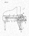
- Fig. 3 is a view showing a back surface of the soundboard 7 for explaining positions at which the acoustic transducers 50 are installed.
- the best way to ensure appropriate electromagnetic coupling between the magnetic-path forming portion 52 and the electromagnetic coupling portion EM is to align the axis C2 of the connecting member R and the axis C1 of the magnetic-path forming portion 52 with each other.
- the axis C2 and the axis C1 are in coaxial alignment with each other for appropriate electromagnetic coupling.
- a portion to which the connecting member R is connected in other words, the pointer member 111 fixed to the soundboard 7, may also be displaced in the horizontal direction.
- the voice coil 513 When the drive signal is input to the voice coil 513, the voice coil 513 receives a magnetic force in the magnetic-path space 525, and the bobbin 511 receives a drive force in the Z-axis direction in accordance with the waveform indicated by the drive signal input to the voice coil 513. Consequently, the electromagnetic coupling portion EM is driven by the magnetic-path forming portion 52, so that the vibrating unit 200 including the electromagnetic coupling portion EM vibrates in the Z-axis direction. When the vibrating unit 200 vibrates in the Z-axis direction, the vibration of the vibrating unit 200 is transmitted to the soundboard 7 by the connecting member R, so that the soundboard 7 is vibrated and sound generated by the vibration of the soundboard 7 are emitted in the air.
- Fig. 6A is a vertical cross-sectional view showing one modified example of the second joint portion J2.
- Figs. 6B and 6C are a plan view and a vertical cross-sectional view showing another modified example of the second joint portion J2.
- the pointer member 111 is fixed to a lower surface 7a of the soundboard 7 by screwing or the like, and the chuck member 112 is threadedly engaged with the pointer member 111.
- the spherical portion 102 of the rod portion 101 is disposed between the tapered surface 111a of the pointer member 111 and the tapered surface 112a of the chuck member 112.
- the chuck member 112 is fastened to the pointer member 111 by being screwed onto the pointer member 111, whereby the tapered surface 111a and the tapered surface 112a cooperate with each other to define the position of the spherical portion 102 in the Z-axis direction.
- the first joint portion J1 in the modified example of Fig. 7B has a structure similar to that of the second joint portion J2 shown in Fig. 5A .
- the first joint portion J1 is disposed near the first end portion 101a.
- a spherical portion 109 is provided at the first end portion 101a of the connecting member R2.
- a lower member 122 is fixed to the cap 512 by bonding or by screws (not shown) while an upper member 121 is fixed to the lower member 122 by screws 123.
- the position of the spherical portion 109 in the Z-axis direction is defined by a tapered surface 121a of the upper member 121 and a tapered surface 122a of the lower member 122.
- the acoustic transducer 50 shown in Figs. 8 and 9 has a secured portion 310 that is secured to the soundboard 7.
- a soundboard-side rod portion 311 is fixed to the secured portion 310 so as to extend downwardly therefrom.
- a spherical portion 312 is provided at a lower end of the soundboard-side rod portion 311.
- the soundboard-side rod portion 311 functions as the fixed portion that is fixed relative to the soundboard 7.
- the soundboard 7 is illustrated as one example of the vibrated body to be vibrated.
- the invention is applicable to a structure in which any other member such as a roof or a side board that undergoes a dimensional change functions as the vibrated body to be vibrated. Even in an instance where the vibrated body does not undergo the dimensional change, the invention is useful when the vibrated body is relatively displaced by a dimensional change or deformation of a member that supports the acoustic transducer, in a direction different from or intersecting the vibration direction.
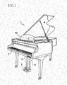
- the piano to which the principle of the invention is applicable may be a grand piano or an upright piano.
- the present invention is applicable to not only the pianos but also various acoustic musical instruments having the acoustic transducer, electronic musical instruments having the acoustic transducer, and speakers.
- the vibrated body that can be forcibly vibrated needs to be provided therein.
- the present invention is applicable to any structure in which the position at which the vibrated body is connected to the movable unit and the position at which the acoustic transducer is supported relatively shift in a direction different from the vibration direction due to a dimensional change or the like.
Landscapes
- Physics & Mathematics (AREA)
- Engineering & Computer Science (AREA)
- Acoustics & Sound (AREA)
- Multimedia (AREA)
- Signal Processing (AREA)
- Electrophonic Musical Instruments (AREA)
- Details Of Audible-Bandwidth Transducers (AREA)
- Audible-Bandwidth Dynamoelectric Transducers Other Than Pickups (AREA)
Applications Claiming Priority (1)
| Application Number | Priority Date | Filing Date | Title |
|---|---|---|---|
| JP2013255847A JP6079600B2 (ja) | 2013-12-11 | 2013-12-11 | 加振器の取付構造 |
Publications (2)
| Publication Number | Publication Date |
|---|---|
| EP2884487A2 true EP2884487A2 (de) | 2015-06-17 |
| EP2884487A3 EP2884487A3 (de) | 2015-08-05 |
Family
ID=52013960
Family Applications (1)
| Application Number | Title | Priority Date | Filing Date |
|---|---|---|---|
| EP14197140.8A Withdrawn EP2884487A3 (de) | 2013-12-11 | 2014-12-10 | Installationsstruktur für akustische Wandler |
Country Status (5)
| Country | Link |
|---|---|
| US (1) | US9532124B2 (de) |
| EP (1) | EP2884487A3 (de) |
| JP (1) | JP6079600B2 (de) |
| KR (1) | KR101687455B1 (de) |
| CN (1) | CN104715746A (de) |
Families Citing this family (12)
| Publication number | Priority date | Publication date | Assignee | Title |
|---|---|---|---|---|
| JP2015138142A (ja) * | 2014-01-22 | 2015-07-30 | ヤマハ株式会社 | 加振器の取付構造 |
| JP2015200828A (ja) * | 2014-04-09 | 2015-11-12 | ヤマハ株式会社 | 加振器の取付構造、楽器、及び、加振器の取付方法 |
| JP6442854B2 (ja) * | 2014-04-09 | 2018-12-26 | ヤマハ株式会社 | 加振器の取付構造、及び、楽器 |
| JP6446896B2 (ja) * | 2014-08-01 | 2019-01-09 | ヤマハ株式会社 | 加振器の取付構造、及び、楽器 |
| JP6378590B2 (ja) * | 2014-09-09 | 2018-08-22 | 株式会社河合楽器製作所 | 電子楽器 |
| CN105120505B (zh) * | 2015-07-28 | 2019-04-16 | 小米科技有限责任公司 | 智能设备接入路由器的方法、装置以及系统 |
| JP6524927B2 (ja) * | 2016-01-20 | 2019-06-05 | ヤマハ株式会社 | 楽器及び加振装置 |
| JP6939254B2 (ja) * | 2017-08-25 | 2021-09-22 | ヤマハ株式会社 | 楽器 |
| CN108169340B (zh) * | 2017-12-18 | 2019-06-21 | 中国船舶科学研究中心(中国船舶重工集团公司第七0二研究所) | 一种机电一体式低频声发射换能器 |
| KR102060760B1 (ko) * | 2018-07-30 | 2020-02-11 | 한국기계연구원 | 압전소자 방식 공작기계 가진 시스템 및 이를 이용한 공작기계 가진 방법 |
| JP7230441B2 (ja) * | 2018-11-09 | 2023-03-01 | ヤマハ株式会社 | 加振ユニット、楽器 |
| CN114503189B (zh) * | 2019-10-18 | 2025-03-25 | 雅马哈株式会社 | 致动器单元及乐器 |
Citations (1)
| Publication number | Priority date | Publication date | Assignee | Title |
|---|---|---|---|---|
| JPH04500735A (ja) | 1988-09-14 | 1992-02-06 | ヴイルヘルム シンメル ピアノフオルテフアブリーク ゲゼルシヤフト ミツト ベシユレンクテル ハフツング | 音響発生装置及び楽器 |
Family Cites Families (21)
| Publication number | Priority date | Publication date | Assignee | Title |
|---|---|---|---|---|
| DE3369217D1 (en) | 1982-02-26 | 1987-02-19 | Prutec Ltd | Improvements in pianos |
| JPS5950031A (ja) | 1982-09-13 | 1984-03-22 | Kemiraito Kogyo Kk | 酸化鉄粉の精製方法 |
| DE3831187A1 (de) | 1988-09-14 | 1990-03-22 | Schimmel Pianofortefab | Vorrichtung zur schallabstrahlung mittels eines plattenfoermigen, elektro-dynamisch angeregten klangkoerpers |
| JPH04116596A (ja) * | 1990-09-06 | 1992-04-17 | Yamaha Corp | 自動ピアノのペダル構造 |
| US5703553A (en) * | 1996-05-24 | 1997-12-30 | Satcon Technology, Corp. | Magnetostrictive active strut |
| GB9905039D0 (en) | 1999-03-05 | 1999-04-28 | New Transducers Ltd | Musical instrument |
| JP4083344B2 (ja) | 1999-04-30 | 2008-04-30 | 山家 清彦 | ピアノのピックアップ装置 |
| US6965679B1 (en) | 2000-10-17 | 2005-11-15 | Alejandro Jose Pedro Lopez Bosio | Equalizable electro-acoustic device used in commercial panels and method for converting said panels |
| US7002070B2 (en) * | 2001-06-22 | 2006-02-21 | Shelley Katz | Electronic piano |
| US7386144B2 (en) | 2004-11-24 | 2008-06-10 | Revolution Acoustics, Ltd. | Inertial voice type coil actuator |
| JP4742574B2 (ja) * | 2004-11-30 | 2011-08-10 | ヤマハ株式会社 | ペダル演奏補助装置 |
| JP4718927B2 (ja) * | 2005-07-29 | 2011-07-06 | パイオニア株式会社 | スピーカ装置 |
| US20070142697A1 (en) | 2005-12-16 | 2007-06-21 | Robert Edwin Schneider | Apparatus for connection of implantable devices to the auditory system |
| JP5486763B2 (ja) | 2007-05-30 | 2014-05-07 | 株式会社河合楽器製作所 | 電子鍵盤楽器 |
| US7825312B2 (en) * | 2008-02-27 | 2010-11-02 | Steinway Musical Instruments, Inc. | Pianos playable in acoustic and silent modes |
| JP2010007835A (ja) | 2008-06-30 | 2010-01-14 | Tokai Rubber Ind Ltd | 能動型流体封入式防振装置 |
| JP2013009268A (ja) | 2011-06-27 | 2013-01-10 | Konica Minolta Business Technologies Inc | データ転送プログラムおよび画像形成装置 |
| US8859866B2 (en) | 2011-09-14 | 2014-10-14 | Yamaha Corporation | Keyboard instrument |
| WO2013089239A1 (ja) * | 2011-12-15 | 2013-06-20 | ヤマハ株式会社 | 楽器の響板を振動させるためのアクチュエータ及びその取り付け方法 |
| JP5560304B2 (ja) | 2012-07-02 | 2014-07-23 | 株式会社河合楽器製作所 | 楽音装置並びに楽音装置の生産方法及び改造方法 |
| JP5846134B2 (ja) | 2013-01-22 | 2016-01-20 | ヤマハ株式会社 | 加振器の取付構造 |
-
2013
- 2013-12-11 JP JP2013255847A patent/JP6079600B2/ja active Active
-
2014
- 2014-12-10 KR KR1020140177341A patent/KR101687455B1/ko active Active
- 2014-12-10 EP EP14197140.8A patent/EP2884487A3/de not_active Withdrawn
- 2014-12-10 US US14/565,931 patent/US9532124B2/en active Active
- 2014-12-11 CN CN201410764295.XA patent/CN104715746A/zh active Pending
Patent Citations (1)
| Publication number | Priority date | Publication date | Assignee | Title |
|---|---|---|---|---|
| JPH04500735A (ja) | 1988-09-14 | 1992-02-06 | ヴイルヘルム シンメル ピアノフオルテフアブリーク ゲゼルシヤフト ミツト ベシユレンクテル ハフツング | 音響発生装置及び楽器 |
Also Published As
| Publication number | Publication date |
|---|---|
| US9532124B2 (en) | 2016-12-27 |
| KR20150068323A (ko) | 2015-06-19 |
| JP2015114457A (ja) | 2015-06-22 |
| US20150163571A1 (en) | 2015-06-11 |
| KR101687455B1 (ko) | 2016-12-19 |
| CN104715746A (zh) | 2015-06-17 |
| EP2884487A3 (de) | 2015-08-05 |
| JP6079600B2 (ja) | 2017-02-15 |
Similar Documents
| Publication | Publication Date | Title |
|---|---|---|
| US9532124B2 (en) | Installation structure for acoustic transducer | |
| US9269335B2 (en) | Installation structure for acoustic transducer | |
| US9373314B2 (en) | Installation structure for acoustic transducer | |
| EP2884486B1 (de) | Installationsstruktur für akustische Wandler | |
| CN106133822B (zh) | 用于声换能器的安装结构以及乐器 | |
| CN106133823A (zh) | 用于声换能器的安装结构、乐器以及声换能器的安装方法 | |
| US10984760B2 (en) | Musical instrument and vibrator | |
| CN111179889B (zh) | 加振单元和乐器 | |
| CN112955949B (zh) | 加振单元、加振器的安装构造、乐器 |
Legal Events
| Date | Code | Title | Description |
|---|---|---|---|
| PUAI | Public reference made under article 153(3) epc to a published international application that has entered the european phase |
Free format text: ORIGINAL CODE: 0009012 |
|
| 17P | Request for examination filed |
Effective date: 20141210 |
|
| AK | Designated contracting states |
Kind code of ref document: A2 Designated state(s): AL AT BE BG CH CY CZ DE DK EE ES FI FR GB GR HR HU IE IS IT LI LT LU LV MC MK MT NL NO PL PT RO RS SE SI SK SM TR |
|
| AX | Request for extension of the european patent |
Extension state: BA ME |
|
| PUAL | Search report despatched |
Free format text: ORIGINAL CODE: 0009013 |
|
| AK | Designated contracting states |
Kind code of ref document: A3 Designated state(s): AL AT BE BG CH CY CZ DE DK EE ES FI FR GB GR HR HU IE IS IT LI LT LU LV MC MK MT NL NO PL PT RO RS SE SI SK SM TR |
|
| AX | Request for extension of the european patent |
Extension state: BA ME |
|
| RIC1 | Information provided on ipc code assigned before grant |
Ipc: H04R 1/02 20060101ALI20150630BHEP Ipc: G10H 3/22 20060101ALI20150630BHEP Ipc: H04R 7/04 20060101ALI20150630BHEP Ipc: H04R 1/00 20060101ALI20150630BHEP Ipc: G10H 1/32 20060101AFI20150630BHEP |
|
| STAA | Information on the status of an ep patent application or granted ep patent |
Free format text: STATUS: THE APPLICATION IS DEEMED TO BE WITHDRAWN |
|
| 18D | Application deemed to be withdrawn |
Effective date: 20160206 |