EP2884196B1 - Klimagerät - Google Patents
Klimagerät Download PDFInfo
- Publication number
- EP2884196B1 EP2884196B1 EP14189954.2A EP14189954A EP2884196B1 EP 2884196 B1 EP2884196 B1 EP 2884196B1 EP 14189954 A EP14189954 A EP 14189954A EP 2884196 B1 EP2884196 B1 EP 2884196B1
- Authority
- EP
- European Patent Office
- Prior art keywords
- module
- fan
- air
- frames
- box
- Prior art date
- Legal status (The legal status is an assumption and is not a legal conclusion. Google has not performed a legal analysis and makes no representation as to the accuracy of the status listed.)
- Active
Links
- 238000000926 separation method Methods 0.000 claims description 66
- 238000005192 partition Methods 0.000 claims description 65
- 238000007789 sealing Methods 0.000 claims description 38
- 238000004891 communication Methods 0.000 claims description 32
- 238000009434 installation Methods 0.000 claims description 26
- 238000003780 insertion Methods 0.000 claims description 6
- 230000037431 insertion Effects 0.000 claims description 6
- 239000012774 insulation material Substances 0.000 claims 1
- 238000010168 coupling process Methods 0.000 description 33
- 230000008878 coupling Effects 0.000 description 31
- 238000005859 coupling reaction Methods 0.000 description 31
- 238000000034 method Methods 0.000 description 25
- 238000002156 mixing Methods 0.000 description 23
- 238000004378 air conditioning Methods 0.000 description 20
- 238000012546 transfer Methods 0.000 description 18
- 230000004888 barrier function Effects 0.000 description 13
- 238000011900 installation process Methods 0.000 description 13
- 230000000694 effects Effects 0.000 description 10
- 230000008569 process Effects 0.000 description 9
- XEEYBQQBJWHFJM-UHFFFAOYSA-N Iron Chemical compound [Fe] XEEYBQQBJWHFJM-UHFFFAOYSA-N 0.000 description 8
- 230000001143 conditioned effect Effects 0.000 description 8
- 239000011810 insulating material Substances 0.000 description 7
- 230000003749 cleanliness Effects 0.000 description 4
- 238000007599 discharging Methods 0.000 description 4
- 229910052742 iron Inorganic materials 0.000 description 4
- 239000007769 metal material Substances 0.000 description 4
- 230000035515 penetration Effects 0.000 description 4
- 230000003068 static effect Effects 0.000 description 4
- 238000003466 welding Methods 0.000 description 4
- 230000006866 deterioration Effects 0.000 description 3
- 239000000463 material Substances 0.000 description 3
- 230000009467 reduction Effects 0.000 description 3
- 239000004952 Polyamide Substances 0.000 description 2
- 229910000831 Steel Inorganic materials 0.000 description 2
- 229910052782 aluminium Inorganic materials 0.000 description 2
- XAGFODPZIPBFFR-UHFFFAOYSA-N aluminium Chemical compound [Al] XAGFODPZIPBFFR-UHFFFAOYSA-N 0.000 description 2
- 230000002457 bidirectional effect Effects 0.000 description 2
- 230000003750 conditioning effect Effects 0.000 description 2
- 238000013461 design Methods 0.000 description 2
- 238000010586 diagram Methods 0.000 description 2
- 230000002708 enhancing effect Effects 0.000 description 2
- 238000001746 injection moulding Methods 0.000 description 2
- 238000009413 insulation Methods 0.000 description 2
- 238000007726 management method Methods 0.000 description 2
- 239000000203 mixture Substances 0.000 description 2
- 238000012986 modification Methods 0.000 description 2
- 230000004048 modification Effects 0.000 description 2
- 229920002647 polyamide Polymers 0.000 description 2
- 238000002360 preparation method Methods 0.000 description 2
- 239000003507 refrigerant Substances 0.000 description 2
- 230000008439 repair process Effects 0.000 description 2
- 239000000565 sealant Substances 0.000 description 2
- 229910052710 silicon Inorganic materials 0.000 description 2
- 239000010703 silicon Substances 0.000 description 2
- 239000010959 steel Substances 0.000 description 2
- 238000010521 absorption reaction Methods 0.000 description 1
- 238000000429 assembly Methods 0.000 description 1
- 230000000712 assembly Effects 0.000 description 1
- 238000005452 bending Methods 0.000 description 1
- 230000005540 biological transmission Effects 0.000 description 1
- 239000000470 constituent Substances 0.000 description 1
- 238000001816 cooling Methods 0.000 description 1
- 230000002542 deteriorative effect Effects 0.000 description 1
- 238000002474 experimental method Methods 0.000 description 1
- 238000001125 extrusion Methods 0.000 description 1
- 239000006260 foam Substances 0.000 description 1
- 238000010438 heat treatment Methods 0.000 description 1
- 238000004519 manufacturing process Methods 0.000 description 1
- 229910052751 metal Inorganic materials 0.000 description 1
- 239000002184 metal Substances 0.000 description 1
- 238000000465 moulding Methods 0.000 description 1
- 239000004033 plastic Substances 0.000 description 1
- 229920003023 plastic Polymers 0.000 description 1
- 239000004814 polyurethane Substances 0.000 description 1
- 230000002265 prevention Effects 0.000 description 1
- 230000005855 radiation Effects 0.000 description 1
- 230000003252 repetitive effect Effects 0.000 description 1
- 230000035939 shock Effects 0.000 description 1
- 239000007779 soft material Substances 0.000 description 1
- 229920003002 synthetic resin Polymers 0.000 description 1
- 239000000057 synthetic resin Substances 0.000 description 1
- 238000009941 weaving Methods 0.000 description 1
Images


Classifications
-
- F—MECHANICAL ENGINEERING; LIGHTING; HEATING; WEAPONS; BLASTING
- F24—HEATING; RANGES; VENTILATING
- F24F—AIR-CONDITIONING; AIR-HUMIDIFICATION; VENTILATION; USE OF AIR CURRENTS FOR SCREENING
- F24F1/00—Room units for air-conditioning, e.g. separate or self-contained units or units receiving primary air from a central station
-
- F—MECHANICAL ENGINEERING; LIGHTING; HEATING; WEAPONS; BLASTING
- F24—HEATING; RANGES; VENTILATING
- F24F—AIR-CONDITIONING; AIR-HUMIDIFICATION; VENTILATION; USE OF AIR CURRENTS FOR SCREENING
- F24F13/00—Details common to, or for air-conditioning, air-humidification, ventilation or use of air currents for screening
- F24F13/20—Casings or covers
-
- F—MECHANICAL ENGINEERING; LIGHTING; HEATING; WEAPONS; BLASTING
- F24—HEATING; RANGES; VENTILATING
- F24F—AIR-CONDITIONING; AIR-HUMIDIFICATION; VENTILATION; USE OF AIR CURRENTS FOR SCREENING
- F24F1/00—Room units for air-conditioning, e.g. separate or self-contained units or units receiving primary air from a central station
- F24F1/0007—Indoor units, e.g. fan coil units
- F24F1/00075—Indoor units, e.g. fan coil units receiving air from a central station
-
- F—MECHANICAL ENGINEERING; LIGHTING; HEATING; WEAPONS; BLASTING
- F24—HEATING; RANGES; VENTILATING
- F24F—AIR-CONDITIONING; AIR-HUMIDIFICATION; VENTILATION; USE OF AIR CURRENTS FOR SCREENING
- F24F13/00—Details common to, or for air-conditioning, air-humidification, ventilation or use of air currents for screening
-
- F—MECHANICAL ENGINEERING; LIGHTING; HEATING; WEAPONS; BLASTING
- F24—HEATING; RANGES; VENTILATING
- F24F—AIR-CONDITIONING; AIR-HUMIDIFICATION; VENTILATION; USE OF AIR CURRENTS FOR SCREENING
- F24F3/00—Air-conditioning systems in which conditioned primary air is supplied from one or more central stations to distributing units in the rooms or spaces where it may receive secondary treatment; Apparatus specially designed for such systems
- F24F3/044—Systems in which all treatment is given in the central station, i.e. all-air systems
-
- E—FIXED CONSTRUCTIONS
- E04—BUILDING
- E04B—GENERAL BUILDING CONSTRUCTIONS; WALLS, e.g. PARTITIONS; ROOFS; FLOORS; CEILINGS; INSULATION OR OTHER PROTECTION OF BUILDINGS
- E04B1/00—Constructions in general; Structures which are not restricted either to walls, e.g. partitions, or floors or ceilings or roofs
- E04B1/38—Connections for building structures in general
- E04B1/61—Connections for building structures in general of slab-shaped building elements with each other
- E04B1/6108—Connections for building structures in general of slab-shaped building elements with each other the frontal surfaces of the slabs connected together
- E04B1/612—Connections for building structures in general of slab-shaped building elements with each other the frontal surfaces of the slabs connected together by means between frontal surfaces
- E04B1/6145—Connections for building structures in general of slab-shaped building elements with each other the frontal surfaces of the slabs connected together by means between frontal surfaces with recesses in both frontal surfaces co-operating with an additional connecting element
- E04B1/6158—Connections for building structures in general of slab-shaped building elements with each other the frontal surfaces of the slabs connected together by means between frontal surfaces with recesses in both frontal surfaces co-operating with an additional connecting element the connection made by formlocking
-
- E—FIXED CONSTRUCTIONS
- E04—BUILDING
- E04B—GENERAL BUILDING CONSTRUCTIONS; WALLS, e.g. PARTITIONS; ROOFS; FLOORS; CEILINGS; INSULATION OR OTHER PROTECTION OF BUILDINGS
- E04B1/00—Constructions in general; Structures which are not restricted either to walls, e.g. partitions, or floors or ceilings or roofs
- E04B1/38—Connections for building structures in general
- E04B1/58—Connections for building structures in general of bar-shaped building elements
- E04B1/5825—Connections for building structures in general of bar-shaped building elements with a closed cross-section
- E04B2001/5856—Connections for building structures in general of bar-shaped building elements with a closed cross-section using the innerside thereof
-
- F—MECHANICAL ENGINEERING; LIGHTING; HEATING; WEAPONS; BLASTING
- F24—HEATING; RANGES; VENTILATING
- F24F—AIR-CONDITIONING; AIR-HUMIDIFICATION; VENTILATION; USE OF AIR CURRENTS FOR SCREENING
- F24F2221/00—Details or features not otherwise provided for
- F24F2221/36—Modules, e.g. for an easy mounting or transport
-
- Y—GENERAL TAGGING OF NEW TECHNOLOGICAL DEVELOPMENTS; GENERAL TAGGING OF CROSS-SECTIONAL TECHNOLOGIES SPANNING OVER SEVERAL SECTIONS OF THE IPC; TECHNICAL SUBJECTS COVERED BY FORMER USPC CROSS-REFERENCE ART COLLECTIONS [XRACs] AND DIGESTS
- Y10—TECHNICAL SUBJECTS COVERED BY FORMER USPC
- Y10T—TECHNICAL SUBJECTS COVERED BY FORMER US CLASSIFICATION
- Y10T29/00—Metal working
- Y10T29/49—Method of mechanical manufacture
- Y10T29/49826—Assembling or joining
Definitions
- An air handler and an assembling of an air handler and a fan module are disclosed herein.
- an air conditioner is a system that cools, heats, or ventilates an air conditioning object space, such as a room or space, by repeating a series of processes including suctioning in of indoor air from the room or space, providing heat exchange between the suctioned in indoor air and a low-temperature or high-temperature refrigerant, and discharging of the heat-exchanged air into the room or space.
- the air conditioner employs a refrigerant cycle comprised of a compressor, an expander, a first heat exchanger, that is, a condenser or evaporator, and a second heat exchanger, that is, an evaporator or condenser.
- Such an air conditioner may be divided into an outdoor unit or device, which is mainly installed outside (also referred to as “outdoor side” or “heat radiation side”) and an indoor unit or device, which is mainly installed inside a building (also referred to as “indoor side” or “heat absorption side”).
- an outdoor unit or device which is mainly installed outside (also referred to as “outdoor side” or “heat radiation side”)
- an indoor unit or device which is mainly installed inside a building
- evaporator that is, an indoor heat exchanger
- air conditioners may be broadly classified into a discrete type air conditioner, in which an outdoor unit and an indoor unit are separately installed, and an integral type air conditioner, in which an outdoor unit and an indoor unit are integrated. Additionally, air conditioners may be classified, based on a magnitude of capacity, into a small capacity air conditioner and a large capacity air conditioner.
- a large capacity air conditioner may include an indoor unit and an outdoor unit integrated with each other, and may be configured to supply conditioned air into a plurality of object spaces requiring air conditioning through ducts, for example.
- An "air handling unit” or “air handler” is one type of large capacity air conditioner, which mixes outdoor air (outside air) and indoor air at an appropriate ratio to suit a target load depending on temperature, humidity, and cleanliness conditions of an object space, thereby providing a user with optimal air conditioning.
- the above-described air handling unit may consist of modules having differentiated functions to ensure efficient driving of a system based on a target load of an object space.
- air handling units are described in KR 10-1294097 B and KR 10-2011-0056109 A .
- an external appearance of the air handling unit is defined by a plurality of frames forming an overall framework of the air handling unit, and a plurality of panels coupled to the plurality of frames.
- the plurality of frames and the plurality of panels define flow passages for the flow of conditioned air.
- the related art air handling units suffer from an excessive number of assembly operations, because the plurality of panels must be coupled to the frames using a lot of screws to achieve a high coupling strength required to prevent leakage of conditioning air. Further, in the related art air handling units, to prevent conditioning air from leaking through gaps between the frames and the panels, it is necessary to primarily wrap electrical insulating tape around outer rim portions of the respective panels. Then, after coupling the plurality of panels to the plurality of frames via the above-described complicated process, it is necessary to secondarily apply a sealant, such as silicon, to regions where air leakage may occur based on a coupling strength between the plurality of frames and the plurality of panels.
- a sealant such as silicon
- the related art air handling units have difficulty in management and transportation of component elements because all of the component elements of the unit must be transported to an installation site and completely assembled on site, and this consequently causes increased logistics and transportation costs.
- the complicated installation process and transportation as described above problematically result in a delay of installation time and increased installation costs.
- DE 197 19 526 A1 relates to an air-conditioning system using a number of individual air-conditioning devices of varying size and/or power rating, each contained within a housing with side, front and rear walls fitted between top and bottom frames. Each housing receives a central device fitted between the frames, incorporating a heat exchanger and an electrical stage, with a fan positioned adjacent the top or bottom frame and associated with a filter.
- an air handling unit as defined in claim 1.
- Preferred embodiments of the invention are defined in claims 2-8.
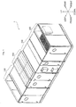
- FIG. 1 is a perspective view of an air handler according to an embodiment.
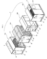
- FIG. 2 is an exploded perspective view of the air handler of FIG. 1 .
- FIG. 3 is a perspective view showing a common assembled form of each module of FIG. 1 .
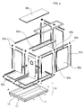
- FIG. 4 is an exploded perspective view of the module of FIG. 3 .
- FIG. 5 is a perspective view showing a connected form of a plurality of module frames of the module of FIG. 3 .
- FIGs. 6A and 6B are exploded perspective views, respectively, showing a connection relationship between an edge frame and a corner connector, and a connection relationship between an edge frame and a middle connector, among the module frames of FIG. 5 .
- FIGS. 7A to 7C are exploded perspective views and partial enlarged perspective views showing a connected form of case panels to a middle frame, among the modules frames of FIG. 5 .
- FIG. 8 is a sectional view taken along line VIII-VIII of FIG. 7A .
- FIGs. 9A and 9B are sectional views, taken along line IX-IX of FIG. 7B , showing examples of various sealing portions between an edge frame among the module frames and a case panel.
- the air handler designated by reference numeral 1
- a target load such as, for example, temperature, humidity, and cleanliness of an object space
- embodiments may be implemented in equivalent implementations of large capacity air conditioners and all other air conditioners, and thus, the scope should not be construed in a narrow sense.
- the air handler 1 may include an air suction module 100, a mixing module 200, a heat exchange module 300, and an air discharge module 400.
- the modules 100 to 400 may be divided based on differentiated functions of an air conditioning cycle. More specifically, the air suction module 100 may have a suction opening 3 to suction in indoor air and accommodate a fan module 101 to move the suctioned in indoor air.
- the mixing module 200 may be coupled to and in communication with the air suction module 100 and serve to mix the indoor air supplied from the air suction module 100 with outside air suctioned in from the outside.
- the heat exchange module 300 may be coupled to and in communication with the mixing module 200 and serve to exchange thermal energy with the mixed air supplied from the mixing module 200.
- the air discharge module 400 may be coupled to and in communication with the heat exchange module 300, may have a discharge opening 9, and may accommodate a fan module 401 to discharge the heat-exchanged air supplied from the heat exchange module 300 to a room through the discharge opening 9.
- the air suction module 100 may function to suction in indoor air through an air suction duct (not shown) that communicates the air suction module 100 with an air conditioning object space (not shown). As such, the air suction module 100 may suction in indoor air and supply the suctioned indoor air to the mixing module 200 located at one side thereof.
- the mixing module 200 may receive the indoor air supplied from the air suction module 100, and simultaneously, suction in outside air from the outside, thereby serving to adjust a mixing ratio of the indoor air and the outside air based on cleanliness, for example, of the air conditioning object space.
- the mixing module 200 may discharge the indoor air supplied from the air suction module 100 within a range of about 0% to 100% and receive the outside air from the outside within a range of about 0% to 100%.
- the mixing module 200 may receive air from the air suction module 100 by a same amount as air discharged therefrom to the outside. For example, when discharging about 30% of air to the outside, the mixing module 200 may receive about 30% of air from the air suction module 100. In this case, the mixing module 200 may mix air supplied from the air suction module 100 and air suctioned from the outside with each other at a mixing ratio of about 7:3. The mixing ratio may be appropriately changed and adjusted in consideration of cleanliness of air or energy efficiency.
- the heat exchange module 300 may perform heat exchange between the mixed air supplied from the mixing module 200 and thermal energy to heat or cool the air to suit a target load of the air conditioning object space, thereby enabling implementation of a cooling operation or heating operation.
- the air discharge module 400 may function to receive the heat-exchanged air from the heat exchange module 300 and discharge the air to a room which is the air conditioning object space.
- the air handler 1 may be divided into four modules 100, 200, 300 and 400 on a per function basis. These modules may be assembled respectively via a combination of a plurality of module frames 20, a plurality of case panels 30, and the internal components 50, which will be described hereinbelow, and be delivered, respectively. Through coupling of the respective assembled modules, a single air handler 1, which is normally operable, may be formed.
- the modular air handler 1 may allow even a normal person rather than a skilled assembler, to simply assemble each module by reading only an installation manual and assemble the full air handler via a combination of the respective modules, and may enable assembly of the air handler with a minimum number of assembly operations by reducing the number of components, and consequently, prevent delay of overall assembly time due to the reduction in the number of components and a number of assembly operations.
- each module includes a base 10 to support a weight of the module, a plurality of the module frames 20 installed on the base 10 to define an external appearance of the module having a predetermined shape, a plurality of the case panels 30 coupled to the plurality of module frames 20 to form surfaces of the module, and a plurality of connecting members or connectors 40 to interconnect the plurality of module frames 20.
- the plurality of module frames 20, as exemplarily shown in FIG. 4 form a framework of the module. More specifically, the plurality of module frames 20 may be assembled into a rectangular parallelepiped-shaped module as two or more module frames 20 are connected to one connecting member 40 to form the framework.
- the plurality of modules frames 20 may include a plurality of edge frames 20a that forms edges of the module, and a plurality of middle frames 20b each having first and second ends connected to the edge frames 20a.
- the middle frames 20b may not be connected to angular points or corners of the module.
- the plurality of module frames 20 may be manufactured by aluminum extrusion or steel molding, for example, and may be formed of a thermal break material to achieve enhanced thermal barrier effects.
- the plurality of edge frames 20a may form respective edges of the rectangular parallelepiped module, or may respectively form a portion of each edge.
- three edge frames 20a may be connected to one corner connector 40a to form each angular point or corner of the module.
- Each of the middle frames 20b may be located between at least two case panels 30, including a lower cover 30a that forms a lower surface of the module, a side cover 30b that forms a side surface of the module, and an upper cover 30c that forms an upper surface of the module.
- the middle frame 20b may bisect the relatively long edge frame 20a, thereby serving to enhance rigidity of an entire module in comparison to a module assembled using only the relatively long edge frames 20a.
- the plurality of connecting members 40 may include corner connectors 40a and middle connectors 40b.
- Each of the corner connectors 40a may form an angular point or corner of the module as three inserting ends 41a, 42a, and 43a of the corner connector 40a arranged substantially perpendicular to one another are connected to the respective edge frames 20a.
- Each of the middle connectors 40b may be connected at two opposite ends thereof to the edge frames 20a and connected at at least one end substantially perpendicular to the two opposite ends to the middle frame 20b in a direction substantially perpendicular to the edge frames 20a.
- the module frames 20, as described above, may be divided into the edge frames 20a and the middle frames 20b in every region forming the framework of the module.
- the edge frames 20a may be connected to one another by one or more corner connectors 40a and middle connectors 40b to form edges of the module.
- the middle frames 20b may be, respectively, located between two case panels 30 and coupled at both ends thereof to the middle connectors 40b. Thereby, as described above, the middle frames 20b may, respectively, bisect the relatively long edge frame 20a or the relatively large case panel 30 to enhance rigidity of the module.
- each of the corner connectors 40a may have the three inserting ends 41a, 42a, and 43a arranged in such a way that any, one inserting end 41a may protrude substantially perpendicular to two inserting ends 42a and 43b.
- the three inserting ends 41a, 42a, and 43a may be inserted into hollow ends 23 of the respective edge frames 20a, which may be coupled to the corner connector 40a to form edges of the module.
- a first screw fastening hole 25 may be formed in the hollow end 23 of the edge frame 20a, and a second screw fastening hole 45 corresponding to the first screw fastening hole 25 may be formed in the inserting end 43a of the corner connector 40a.
- each of the middle connectors 40b may have three inserting ends 41b, 42b and 43b arranged in such a way that any one inserting end 43b (hereinafter referred to as “third inserting end 43b") may protrude substantially perpendicular to two inserting ends 41 b and 42b (hereinafter referred to as “first inserting end 41b” and “second inserting end 42b", respectively, and the first inserting end 41b and the second inserting end 42b may be linearly arranged to protrude in opposite directions.
- the third inserting end 43b may be inserted into a hollow end (not shown) of the middle frame 20b, and the first inserting end 41 b and the second inserting end 42b may be, respectively, inserted into the hollow ends 23 of the edge frames 20a.
- a screw fastening hole (not shown) corresponding to the first screw fastening hole 25 of the edge frame 20a may be formed in the third inserting end 43b of the middle connector 40b
- a screw fastening hole (not shown) corresponding to the screw fastening hole of the middle connector 40b may be formed in the middle frame 20b
- the second screw fastening hole 45 corresponding to the first screw fastening hole 25 of the edge frame 20a may be formed in each of the first inserting end 41b and the second inserting end 42b of the middle connector 40b.
- the first inserting end 41b and the second inserting end 42b of the middle connector 40b may be, respectively, inserted into and coupled to the hollow ends 23 of the edge frames 20a arranged at opposite sides thereof, and the third inserting end 43b of the middle connector 40b may be inserted into and coupled to the hollow end (not shown) of the middle frame 20b.
- Each of the module frames 20 is provided with one or more sliding ribs 21' and 21" that protrude outward in a direction substantially perpendicular to a longitudinal direction of the frames.
- the sliding ribs 21' and 21" as will be described hereinbelow, are fitted into sliding rail grooves 31 formed in a rim or at outer edges of the case panels 30.
- the sliding ribs 21' and 21" of each module frame 20 may be equal in number to a number of the case panels 30 to be connected to the module frame 20.
- the edge frame 20a which may be disposed immediately above the base 10 among the module frames 20, may be provided with two sliding ribs 21' and 21". More specifically, the two sliding ribs 21' and 21" may include a first sliding rib 21' inserted into the sliding rail groove 31 formed in a rim of the case panel 30 that forms a lower surface of the module, that is, the lower cover 30a, and a second sliding rib 21' inserted into the sliding rail groove 31 formed in a lower end rim of the case panel 30 that forms a side surface of the module, that is, the side cover 30b.
- the middle frame 20b which may extend along a middle portion of the case panel 30 that forms a lower surface of the module, that is, the lower cover 30a, may be provided with three sliding ribs 21' and 21". More specifically, the middle frame 20b may be provided with a pair of sliding ribs inserted into the sliding rail grooves 31 formed in rims of the case panels 30 arranged at horizontal opposite sides of the middle frame 20b.
- the middle frame 20b may further be provided with a third sliding rib 21" inserted into the sliding rail groove 31 formed in the rim of the case panel (not shown) above the middle frame 20b.
- the middle frame 20b is provided at the side cover 30b or the upper cover 30c.
- sealing pads 47 may be interposed, respectively, between the inserting ends 41a, 42a, and 43a of the corner connector 40a and ends of the module frames 20.
- the sealing pads 47 may be configured to come into close contact with the module frames 20 and the corner connector 40a upon coupling of the module frames 20 and the corner connector 40a, thereby serving to block gaps between the module frames 20 and the corner connector 40a to prevent leakage of air from the module.
- each of the sealing pads 47 may have an end penetration hole 48a for penetration of the inserting end 41a, 42a, or 43a of the corner connector 40a. As such, the sealing pad 47 may completely seal a gap between the module frame 20 and the corner connector 40a except for a space for penetration of the inserting end 41a, 42a, or 43a.
- the sealing pad 47 may have a same shape as the hollow end 23 of the module frame 20 to prevent the end of the module frame 20 from coming into contact with the corner connector 40a.
- the sealing pad 47 may also serve to prevent leakage of energy by reducing high metal-to-metal thermal conductivity.
- the sealing pad 47 may be interposed between the middle connector 40b and the middle frame 20b, or between the middle connector 40b and the edge frame 20a.
- the sealing pad 47 may be fitted to each inserting end 41a, 42a, or 43a (41b, 42b, or 43b) of the connecting member 40, thereby assisting the inserting end 41a, 42a, or 43a (41b, 42b, or 43b) of the connecting member 40 in being sealed upon insertion into the end of the module frame 20.
- the module frames 20 and the connecting members 40 may be assembled with one another to form a framework of a rim of the lower cover 30a.
- the module frames 20, more particularly, the edge frames 20a may be assembled with one another using only the corner connectors 40a to form a simple rectangular framework
- the middle frames 20b and the middle connectors 40b may be additionally used to bisect the rectangular framework.
- rigidity of an entire module may be enhanced as the middle frame 20b may be used to divide the relatively long edge frame 20a into two members.
- any one edge frame 20a may be omitted to open one side of the framework. This may serve to allow sliding coupling between the sliding ribs 21' and 21" of the module frames 20 and the sliding rail grooves 31 formed in the rim of the lower cover 30a. Thereby, as the lower cover 30a may horizontally slide through the open side of the framework, the sliding ribs 21' and 21" may be inserted into the sliding rail grooves 31.
- the case panel 30 may be coupled to the module frames 20 via sliding thereof toward a closed opposite side of the framework.
- sliding coupling of the case panel 30 to the module frames 20 may not be absolutely necessary, and conversely, sliding coupling may be performed in such a way that the sliding ribs 21' and 21" of the module frames 20 may be fitted into the sliding rail grooves 31 of the case panel 30.
- the air handler 1 may be assembled by combining the above-described two sliding coupling methods, and provide diversity of assembly to allow an assembler to select a best method to improve assembly efficiency in consideration of an assembly environment on site or propensity of the assembler.
- coupling between the module frames 20 and the case panels 30 may be performed via sliding coupling without using screws, which may considerably reduce a number of assembly operations using screws and prevent deterioration of rigidity in screw fastening regions.
- a plurality of frames is coupled to one another to form the framework of an air handler via screw fastening or welding, and an inconvenient sealing operation to isolate an interior of the air handler from the outside must be performed after fitting case panels into openings corresponding to a shape of the case panels.
- an inconvenient sealing operation to isolate an interior of the air handler from the outside must be performed after fitting case panels into openings corresponding to a shape of the case panels.
- a rim of each case panel is wrapped using electrical insulating tape prior to fitting the case panel into the opening.
- a sealant such as silicon
- each of the case panels 30 may include an inner plate 32a forming an inner surface of the module, an outer plate 32b outwardly spaced substantially in parallel from the inner plate 32a by a predetermined distance to form an outer surface of the module, a joint member 34 to finish ends of the inner plate 32a and the outer plate 32b along rims thereof, and a heat insulating material 33 filled between the inner plate 32a and the outer plate 32b.
- the inner plate 32a and the outer plate 32b may be formed of a metallic material in consideration of rigidity of the entire module.
- the heat insulating material 33 filled between the inner plate 32a and the outer plate 32b may serve to prevent conditioned air from radiating heat to the outside.
- the heat insulating material 33 may be polyurethane (PU) foam.
- a thickness of the case panel 30 corresponding to a distance between the inner plate 32a and the outer plate 32b may be set to an appropriate value in consideration of a volume of the entire air handler 1 and heat insulation effects of the heat insulating material 33.
- assembly of each module may be completed in a simplified manner using only sliding coupling between the module frames 20 and the case panels 30 without requiring the complicated screw fastening and welding of the related art, and the above-described additional sealing operation may be unnecessary. Accordingly, assembly of the air handler 1 may be accomplished in a simplified manner by a few assemblers and with a reduced number of assembly operations. In particular, as will be described below, according to one embodiment of the air handler 1, an additional sealing operation beyond sliding coupling between the module frames 20 and the case panels 30 may be unnecessary.
- the middle frame 20b may have a heat transfer barrier 26 to prevent transfer of heat from the interior of the module to the outside.
- the heat transfer barrier 26 may have not only a heat transfer prevention function, but also a general sealing function to prevent leakage of air by coming into close contact with an outer end surface of the sliding rail groove 31 of the case panel 30. More specifically, with reference to FIG.
- the middle frame 20b may include a first frame 20b' arranged close to an inner space of the module, the first frame 20b' forming a first hollow region 23a having a closed cross section, and a second frame 20b" spaced from the first frame part 20b' by a predetermined distance and arranged close to the outside of the module, the second frame 20b" forming a second hollow region 23b having a closed cross section.
- the heat transfer barrier 26 may be a connector that interconnects the first frame 20b' and the second frame 20b".
- the sliding ribs 21' and 21" may be formed at the second frame 20b" having the second hollow region 23b, and the first frame 20b' may have a sliding rib (not shown) corresponding to the above-described sliding rib, so as to be fitted into the sliding rail groove 31 of the case panel 30, which may be provided to cross the inner space of the module as needed.
- the heat transfer barrier 26 may include a pair of connectors that interconnect the first frame 20b' and the second frame 20b" to form a third hollow region 23c having a closed cross section between the first frame 20b' and the second frame 20b".
- the first frame 20b' and the second frame 20b" of the middle frame 20b may be formed of a metallic material including aluminum or steel in consideration of rigidity of the framework of the module.
- the heat transfer barrier 26 may be formed of polyamide. As is well known in the art, polyamide is an electrical insulating material and may serve to minimize a heat transfer structure by preventing the metallic case panel 30 from coming into contact with the metallic middle frame 20b upon sliding coupling of the case panel 30 and the middle frame 20b.
- the first to third hollow regions 23a, 23b, and 23c formed in the middle frame 20B may serve as heat insulating layers that cause minimum air convection as long as there are no special circumstances.
- the first to third hollow regions 23a, 23b, and 23c may serve not only to reduce a weight of the middle frame 20b, but also to provide the middle frame 20b with protruding portions to increase a perimeter of the entire middle frame 20b, which may increase transverse rigidity of the middle frame 20b.
- first to third hollow regions 23a, 23b, and 23c may be arranged in sequence from an inner side to an outer side of one middle frame 20b, thereby serving to extremely minimize transfer of heat from the interior of the module to the outside.
- the heat transfer barrier 26 may be interposed between the metallic first frame 20b' and the metallic second frame 20b", respectively, located close to the inner space of the module and the outside of the module, thereby serving to interconnect the frames 20b' and 20b" and to minimize heat transfer.
- the first frame 20b' and the second frame 20b" may have retaining portions 27 by which ends of the heat transfer barrier 26 may be caught. More specifically, both ends of the heat transfer barrier 26 may be arranged to come into contact with facing surfaces of the first frame 20b' and the second frame 20b" and have a triangular cross section, one side of which may come into surface contact with the corresponding retaining portion.
- the retaining portions 27 may be arranged at both sides of each end of the heat transfer barrier 26 to surround the end of the heat transfer barrier 26, thereby serving to firmly grip and secure the end of the heat transfer barrier 26.
- the heat transfer barrier 26 may be coupled to the first frame 20b' and the second frame 20b" via, for example, fitting or welding, embodiments are not limited by the aforementioned coupling method.
- the case panel 30, as described above, may include the inner plate 32a forming an inner surface of the module, the outer plate 32b outwardly spaced substantially in parallel from the inner plate 32a by a predetermined distance to form an outer surface of the module, the joint member 34 for finishing of ends of the inner plate 32a and the outer plate 32b along rims thereof, and the heat insulating material 33 filled between the inner plate 32a and the outer plate 32b.
- the sliding rail groove 31, into which the sliding rib 21' or 21" of each of the module frames 20 may be slidably fitted, may be formed in the joint member 34 of the case panel 30.
- the joint member 34 may be formed of a non-metallic material having low thermal conductivity, and may be formed of an easily moldable synthetic resin material, such as plastic.
- the sliding rail groove 31 may be formed throughout the rim of the case panel 30, and may have an approximately " "-shaped cross section so as to be indented to allow insertion of the sliding rib 21' or 21" therein.
- the case panel 30 may further include sealing portions 35a and 35b to prevent leakage of air from a gap between the module frame 20, more particularly, the edge frame 20a, and the case panel 30 upon sliding coupling of the case panel 30 and the edge frame 20a.
- the sealing portions 35a and 35b may be formed in the sliding rail groove 31 and may be integrally formed with the joint member 34 by, for example, injection molding.
- the sliding rail groove 31, as described above, may have a " "-shaped cross section, one end of which may be open for insertion of the sliding rib 21' or 21" of the edge frame 20a thereinto, and the sealing portions 35a, 35b may, respectively, protrude from a first surface 31a and a second surface 31b, adjacent to the open end of the sliding rail groove 31, toward opposite surfaces by a predetermined consistent length.
- a thickness D1' of the sliding rib 21' or 21" of the edge frame 20a may be less than a width D3' of the sliding rail groove 31 of the case panel 30 and greater than at least a distance D2' between tip ends of the sealing portions 35a that protrude from the opposite surfaces of the sliding rail groove 31.
- the sliding rib 21' or 21" of the edge frame 20a when the sliding rib 21' or 21" of the edge frame 20a is inserted into the sliding rail groove 31 of the case panel 30, the sliding rib 21' or 21" may be inserted into the sliding rail groove 31 so as not to come into contact with the sliding rail groove 31, and the sealing portions 35a may hermetically come into close contact with an outer surface of the sliding rib 21 or 21", resulting in enhanced sealing performance.
- the sealing portions 35a may, respectively, protrude from the first surface 31a and the second surface 31b of the sliding rail groove 31 in opposite directions by the predetermined consistent length, and the distance D2' between the tip ends of the respective sealing portions 35a may be less than the thickness D1' of the sliding rib 21 or 21" inserted into the sliding rail groove 31.
- the sliding rail groove 31 may have a " "-shaped cross section, one end of which may be open for insertion of the sliding rib 21' or 21" of the edge frame 20a, a length D2" of the open end 34a may be less than a distance D4 between the first surface 31a and the second surface 31b of the sliding rail groove 31 (see reference letter " ⁇ " of FIG. 9B ), the sealing portions 35b may, respectively, protrude from the first surface 31a and the second surface 31b, adjacent to the open end 34a of the sliding rail groove 31, toward the opposite surfaces by a predetermined consistent length, and a distance D3" between the protruding sealing portions 35b may be less than the length D2" of the open end 34a.
- the sealing portions 35b may, respectively, protrude from the first surface 31a and the second surface 31b of the sliding rail groove 31 in opposite directions by the predetermined consistent length, and the distance D3" between the tip ends of the respective protruding sealing portions 35b may be less than the length D2" of the open end 34a of the sliding rail groove 31.
- the sealing portions 35b may protrude, respectively, from the first surface 31a and the second surface 31b of the sliding rail groove 31 by the predetermined consistent length, and the distance D3" between the tip ends of the respective protruding sealing portions 35b may be less than a thickness D1" of the sliding rib 21' or 21" inserted into the sliding rail groove 31.
- the sealing portions 35a and 35b may be integrally formed in the sliding rail groove 31 of the joint member 34 by, for example, injection molding.
- a portion of the joint member 34, in which the sliding rail groove 31 may be formed, may be formed of a hard material to maintain rigidity of the module.
- the sealing portions 35a and 35b may be formed of a soft material, and thus, may be deformed to some extent upon insertion of the sliding rib 21' or 21" of the edge frame 20a, thereby coming into close contact with the sliding rib 21' or 21".
- heat insulation performance may be primarily enhanced by the heat insulating material 33 between the metallic inner plate 32a and the metallic outer plate 32b of the case panel 30, and hermetic sealing performance to prevent leakage of air may be secondarily enhanced by the sealing portions 35a and 35b of the case panel 30.
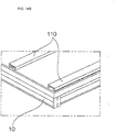
- FIG. 10 is a perspective view showing a common base included in each module of FIG. 1 .
- FIG. 11 is an exploded perspective view showing a coupled form of the base of FIG. 10 and a lower cover.
- FIG. 12 is a partial perspective view showing a coupled form of modules of FIG. 1 using bases thereof.
- the base 10 may be a lowermost element of the module, and serve to support a weight of the entire module.
- the base 10 may be a combination of a plurality of base frames 11a, 11b, and 15.
- the base frames 11a, 11b, and 15 may be elongated in a longitudinal direction thereof and have a " "-shaped cross section, one longitudinal side of which is open.
- the base frames 11a, 11b, and 15 may be arranged such that the open side 12 of each base frame is oriented outward and may be assembled with one another using screws S.
- the base 10 may have an approximately rectangular shape to allow the rectangular parallelepiped module to be stably disposed thereon, and the one or more base frames 11a, 11b, and 15 may be arranged substantially in parallel at a center of the base 10 as needed to effectively support any one of modules having various sizes and weights thereon.
- the base 10, with reference to FIG. 10 may be assembled such that the open sides 12 of all of the base frames 11a, 11b, and 15 are oriented outward. This serves to facilitate assembly between the modules, as will be described hereinbelow.
- the base frames 11a, 11b, and 15 may have first screw fastening holes 14 formed in both ends thereof for fastening of the screws S.
- second screw fastening holes 13, see FIG. 12
- the base frames 11a, 11b, and 15 may include first base frames 11a forming longer sides, second base frames 15 forming shorter sides, and a middle base frame 11b that interconnects the second base frames 15 for rigidity enhancement.
- the base 10 which may have a rectangular shape via a combination of the base frames 11a, 11b, and 15, may be provided at an upper end rim thereof with a plurality of mounting brackets 17 spaced apart from one another by a predetermined distance.
- the plurality of mounting brackets 17 may serve to assist coupling of screws S and the rim of the lower cover 30a of the module.
- the respective mounting brackets 17 may have screw fastening holes 18 to couple the screws S through the lower cover 30a and the base 10.
- Upper ends of the plurality of mounting brackets 17 may be bent to come into surface contact with a slope, which may be formed at a rim of the lower cover 30a.
- the air suction module 100, the mixing module 200, the heat exchange module 300, and the air discharge module 400 may be hermetically coupled to one another to prevent leakage of air while being in communication with one another.
- the base frames 11a, 11b, and 15 forming the base 10 may have a " "-shaped cross section to form the open side 12, and connection flanges 16 for interconnection of the bases 10 of the respective modules may be formed at both ends of the base frames 11a, 11b, and 15.
- the connection flanges 16 of each module may be provided with bolt fastening holes 16a that communicate with the open side 12 of each of the base frames 11a, 11b, and 15. In a state in which the connection flanges 16 of the respective modules come into surface contact with one another, bolts B may penetrate the bolt fastening holes 16a and nuts N may be fastened to the bolts B to interconnect the respective modules.
- the bolt fastening holes 16a may be replaced with the above-described screw fastening holes 14, the bolt fastening holes 16a may be formed separately from the screw fastening holes 14.
- the modules 100, 200, 300, and 400 which may be respectively assembled on a per function basis, may be arranged in sequence, and the bases 10 of the respective modules interconnected, the air handler 1 according to embodiments capable of forming a single air conditioning cycle may be completed.
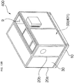
- FIGs. 13A-13B are perspective views showing an air suction module and an air discharge module of FIG. 1 , both of which are configured to receive a fan module.
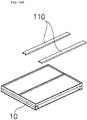
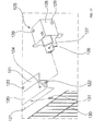
- FIGs. 14A-14B are perspective views showing a preparation operation to install a fan module to a base.
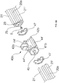
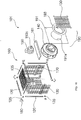
- FIG. 15 is a perspective view of the fan module of FIGs. 14A-14B .
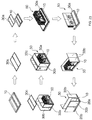
- FIG. 16 is an exploded perspective view of the fan module of FIG. 15 .
- FIG. 17 is an exploded perspective view showing an installation relationship between a box frame, a box frame connector, and a safety net of the fan module of FIG. 15 .
- FIG. 18 is a perspective view showing a coupled form of the fan module of FIG. 15 and a lower cover.
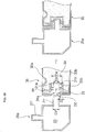
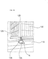
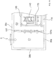
- FIG. 19 is a partial sectional view showing an interior of the air suction module or the air discharge module according to an embodiment, which is divided into an air suction chamber and a centrifugal chamber by a separation partition.
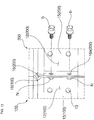
- FIG. 20 is a perspective view showing a stacked installation form of fan modules according to an embodiment.
- the air handler 1, as described above which may include the air suction module 100 having the suction opening 3 for suction of indoor air and accommodating fan module 101 to move the suctioned indoor air, the mixing module 200 coupled to and in communication with the air suction module 100 and mixing the indoor air supplied from the air suction module 100 and outside air suctioned from the outside, the heat exchange module 300 coupled to and in communication with the mixing module 200 and exchanging thermal energy with the mixed air supplied from the mixing module 200, and the air discharge module 400 coupled to and in communication with the heat exchange module 300 and accommodating the fan module 401 to discharge the heat-exchanged air supplied from the heat exchange module 300 to a room through the discharge opening 9.
- the components 50 for differentiated functions may be incorporated in inner spaces of the respective modules.
- the components 50 for differentiated functions may be installed in the most efficient manner in the inner spaces of the respective modules having a standardized shape.
- the air suction module 100 and the air discharge module 400 respectively include a suction chamber C1 for suctioning in air and a centrifugal chamber C2 separated from the suction chamber C1 by a separation partition 107, the fan module 101 or 401 being installed in the centrifugal chamber C2 (see FIG. 19 ).
- the separation partition 107 being one of the case panels 30 is slidably coupled to the middle frame 20b in the same manner as the other case panels 30. More specifically, the separation partition 107 is be one of the case panels 30, both ends of which are vertically slidably inserted into and coupled to the module frames 20 forming the framework of the module. As such, the separation partition 107 separates the suction chamber C1 and the centrifugal chamber C2 from each other in a direction substantially perpendicular to a flow direction of conditioned air.
- the separation partition 107 is slidably coupled to the module frames 20 located, respectively, between two case panels 30, that is, the middle frames 20b. More specifically, the separation partition 107 may be slidably coupled to the middle frame 20b on the lower cover 30a formed by dividing a lower surface of the module into two sections and may also be slidably coupled between the middle frames 20b vertically extending upward from the middle connectors 41b located at both ends of the middle frame 20b on the lower cover 30a.
- the separation partition 107 may have a rectangular communication opening 107a for communication between the suction chamber C1 at a first side of the separation partition 107 and the centrifugal chamber C2 at a second side of the separation partition 107.
- the communication opening 107a may not be limited to the rectangular shape and may have any of various other shapes.
- the separation partition 107 may be mounted on the lower cover 30a forming a lower surface of the air suction module 100 or the air discharge module 400. More specifically, the lower cover 30a may be formed by two case panels 30 horizontally coupled, respectively, to a first side and a second side of the middle frame 20b that crosses a middle portion of the lower cover 30a in a direction substantially perpendicular to a flow direction of conditioned air, and the separation partition 107 may be coupled to the lower cover 30a such that the sliding rib 21' or 21" protruding upward from the middle frame 20b on the lower cover 30a may be inserted into the sliding rail groove 31 formed in a lower end of the separation partition 107.
- the separation partition 107 may be further provided at both lateral ends thereof with the sliding rail grooves 31, such that the sliding ribs 21' or 21" of the middle frames 20b vertically connected to the middle connectors 40b at both ends of the middle frame 20b on the lower cover 30a, may be inserted into the respective sliding rail grooves 31 to allow the separation partition 107 to be slidably coupled to the middle frames 20b.
- the fan module 101 or 401 accommodated in the centrifugal chamber C2 may be connected to the separation partition 107 through the communication opening 107a.
- the fan module 101 or 401 which may be connected to the separation partition 107 and accommodated in the centrifugal chamber C2, may serve to create centrifugal force by suctioning in air from the suction chamber C1 to the centrifugal chamber C2 and discharging the air to another neighboring module (for example, the mixing module 200) or to the outside.
- the fan module 101 or 401 may include a centrifugal fan 140 to create the aforementioned suction force and centrifugal force, a fan motor 150 to apply torque to the centrifugal fan 140, and a fan box 160 having an installation space for the centrifugal fan 140 and the fan motor 150.
- the fan box 160 may be located in the centrifugal chamber C2 at one side of the separation partition 107 so as to be spaced from the separation partition 107.
- the fan box 160 may include a plurality of box frames 120 that form the framework of the fan box 160, and safety nets 130 installed on the box frames 120 to form surfaces of the fan box 160, the safety nets 130 serving to protect rotation of the centrifugal fan 140.
- the separation partition 107 and the fan box 160 may be connected to each other to allow air suctioned through the communication opening 107a to move to the centrifugal fan 140. That is, the fan box 160 may be coupled to the communication opening 107a of the separation partition 107 to allow interior air of the suction chamber C1 to wholly pass through the centrifugal fan 140 installed in the fan box 160 of the centrifugal chamber C2. This will be described hereinbelow in detail.
- the fan box 160 may be assembled into a predetermined external appearance of a framework using a box frame connector 125 that interconnects two or more box frames 120 at each corner of the box frame 160.
- the fan box 160 may have a rectangular parallelepiped shape internally defining a predetermined installation space for the centrifugal fan 140 and the fan motor 150.
- the box frame connector 125 may be located at each corner of the rectangular parallelepiped frame box 160 to interconnect three box frames 120 substantially perpendicular to one another.
- the box frames 120 may be, for example, formed of iron, have a triangular hollow section 122, and include extensions 121 substantially parallel to respective surfaces of the fan box 160.
- a portion 126 of the box frame connector 125 may be inserted into the triangular hollow section 122 so as to overlap a portion of the box frame 120.
- screws S are fastened through screw fastening holes 124 and 127 formed, respectively, in the portion 126 of the box frame connector 125 and the overlapped portion of the box frame 120, the box frame 120 and the box frame connector 125 may be assembled with each other.
- the box frame connector 125 may have an outwardly extending fan box connection end 128 for connection of neighboring fan modules 101 or 401 when a plurality of fan modules 101 or 401 is stacked one above another or arranged side by side in the centrifugal chamber C2.
- the fan box connection end 128 may have a " "-shaped or " “-shaped form to extend in substantially vertical and horizontal directions. As such, the fan box connection end 128 may be used to interconnect the fan modules 101 or 401 arranged side by side, as well as the fan modules 101 or 401 stacked one above another.
- the fan box connection end 128 may have a screw fastening hole 129 to allow a screw S to be fastened through the screw fastening holes 129 of neighboring fan box connection ends 128.
- the fan box connection end 128 may be integrally formed with the box frame connector 125 and may also be prefabricated separately from the box frame connector 125 and then separably connected to the box frame connector 125 or the box frame 120 as needed.
- the safety nets 130 may take the form of a mesh formed, for example, by welding a plurality of iron wires, or by weaving the iron wires to make knots.
- the safety nets 130 may be coupled to the framework formed by the box frames 120 to form surfaces of the fan box 160, as described above.
- the safety nets 130 may function to protect rotation of the centrifugal fan 140 installed in the fan box 160 and rotated at high speeds.
- the safety nets 130 may serve to pass air to assist the case panels 30 forming surfaces of the centrifugal chamber C2, rather than a fan housing enclosing the centrifugal fan 140, in guiding movement of air by static pressure generated by rotation of the centrifugal fan 140. This is based on the principle that a predetermined static pressure is generated when the centrifugal fan C2 is filled with moving air.
- a separate fan housing is not necessary.
- the safety nets 130 may be coupled to the box frames 120 so as to form surfaces of the rectangular parallelepiped fan box 160 except for a surface of the fan box 160 adjacent to the separation partition 107 and a lower surface of the fan box 160. This is because a fan shield 191, which will be described hereinbelow, may be coupled to the surface of the fan box 160 adjacent to the separation partition 107, and the lower surface of the fan box 160 may not be involved in protection of rotation of the centrifugal fan 140.
- each safety net 130 may include a plurality of outwardly extending connection rings 131 spaced apart from one another by a predetermined distance along the rim of the safety net 130 so as to be inserted into screw holes 123 formed in the extension 121 of the box frame 120.
- the connection rings 131 may be formed by bending some of the iron wires into a rounded form, and may also be prefabricated as separate members, and then, may be attached to the rim of the safety net 130.
- the connection rings 131 may assist installation of the safety net 130 to the box frame 120, as screws S are fastened through the screw holes 123 of the box frame 120.
- corner-shaped support members 180 may be coupled to support corners of the fan box 160.
- the fan module 101 or 401 having the above-described configuration may be installed above the lower cover 30a disposed on the base 10 and a pair of fan module brackets 110 mounted on the lower cover 30a so as to be spaced apart substantially in parallel from each other by a predetermined distance.
- the fan module brackets 110 may serve to prevent the fan module 101 or 401 from being directly disposed on the lower cover 30a so as to come into contact with the lower cover 30a.
- the fan module bracket 110 may be coupled to the fan box connection end 128 of each box frame connector 125 located at a lower end of the fan box 160 with a vibration absorbing block 105 interposed therebetween, which may prevent vibration caused by operation of the centrifugal fan 140 of the fan module 101 or 401 from being directly transmitted to the lower cover 30a.
- FIG. 21 is a perspective view showing the centrifugal fan of the fan module of FIG. 15 .
- FIGs. 22A-22B are sectional views showing vertical cross sections of a blade included in the centrifugal fan of FIG. 21 .
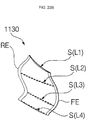
- the centrifugal fan 140 is a fan that accelerates air introduced in an axial direction through a fan shroud 1120 and discharges the air in a radial direction through gaps between blades 1130 by centrifugal force. Performance of the centrifugal fan 140 may be affected by various shape factors, as well as friction loss, and shock loss, for example.
- the centrifugal fan 140 which may be one component of the fan module 101 or 401, may be configured such that an upper portion 1132 of each blade 1130 defines a section that is concave toward a rotational axis O, and a lower portion 1131 of the blade 1130 may define a section that is convex in a direction opposite to the rotational axis O.
- This shape of the blade 1130 may reinforce airflow at the lower portion 1131 of the blade 1130 and ensure even airflow between the upper and lower portions 1132, 1131 of the blade 1130, which may provide the centrifugal fan 140 with reduced noise generation and greatly enhanced performance in comparison to conventional fans having a same size or volume.
- the centrifugal fan 140 may include a pair of main plates 1110 configured to be rotated about the rotational axis O, the fan shroud 1120 having an air suction hole 1121 and the blades 1130 arranged in a circumferential direction between the main plates 1110 and the fan shroud 1120, such that air suctioned through the suction hole 1121 moves from front edges FE to rear edges RE of the blades 1130.
- layers Layer 1 to Layer 4 of each blade 1130 taken in sequence from the fan shroud 1120 to the main plates 1110, have a first cross section S(L1), a second cross section S(L2), a third cross section S(L3), and a fourth cross section S(L4).
- a front edge of the first cross section S(L1) may be farther from the rotational axis O than a front edge of the fourth cross section S(L4)
- a rear edge of the first cross section S(L1) may be closer to the rotational axis O than a rear edge of the fourth cross section S(L4).
- a rear edge of the second cross section S(I2) may be located farthest away from the rotational axis O, and the rear edge of the third cross section S(L3) may be closest to the rotational axis O.
- the blades 1130 may have a 3D shape.
- the 3D shape of the blades 1130 may be defined as a shape in which, when cross sections of the blade 1130 taken at predetermined layers corresponding to predetermined planes substantially perpendicular to the rotational axis O are projected onto a predetermined projection plane in a direction of the rotational axis O, two or more lines among lines interconnecting the front edges FE and the rear edges RE of the respective cross sections in the projection plane do not overlap each other.
- the centrifugal fan 140 having the 3D shape of the blades 1130 as described above has increased static pressure, as well as efficiency depending on a same air volume in comparison to conventional centrifugal fans. More particularly, the centrifugal fan 140 has maximum efficiency up to approximately 82% in comparison to an efficiency of approximately 70% of the related art based on the same air volume.
- Such enhancement in performance of the centrifugal fan allows the fan to be driven at a lower speed than the related art with respect to the same air volume. In turn, that this lower driving speed is possible means that the air handler 1 according to embodiments may be sufficiently driven by a lower driving load of the fan motor 150 upon high speed driving under the same conditions.
- a single fan module 101 or 401 may be installed in the centrifugal chamber C2 and a plurality of fan modules 101 or 401 may be vertically or horizontally arranged substantially in parallel in the centrifugal fan C2 to suit a continuously variable target load of an air conditioning object space. This is because the fan motor 150 and the centrifugal fan 140 having the 3D shape are reduced in volume, and thus, it is unnecessary to construct a large size fan module having installation and transportation inconvenience.
- the fan module 101 or 401 may include the centrifugal fan 140, which may suction in air from the suction chamber C1 into a space between the main plates 1110 vertically oriented and spaced apart from each other in a direction of the rotational axis and radially discharge the air to the centrifugal chamber C2 through gaps between the blades 1130 interconnecting the main plates 1110; the fan motor 150, which may apply torque to the centrifugal fan 140 and which may be linearly coaxial with the rotational axis of the centrifugal fan 140; the fan box 60 having an installation space for the centrifugal fan 140 and the fan motor 150, and a guide 190 installed in the fan box 160 and defining an air introduction passage from the suction chamber C1 to the space between the main plates 1110 of the centrifugal fan 140.
- the centrifugal fan 140 which may suction in air from the suction chamber C1 into a space between the main plates 1110 vertically oriented and spaced apart from each other in a direction of the rotational
- the centrifugal fan 140 has the above-described 3D shape, and thus, requires a relatively small size or small volume for generation of the same air volume.
- the centrifugal fan 140 may be rotated in the fan box 160, which forms the fan module 101 or 401, thereby creating airflow power for suctioning in air from the suction chamber C1 and for discharging the air from the centrifugal chamber C2.
- the fan module 101 or 401 may further include a motor bracket 170 for the fan motor 150, which may have a smaller vertical height than a vertical height of the centrifugal fan 140, installed in the fan box 160 such that a rotational shaft 150c of the fan motor 150 may be horizontally coaxial with the rotational center of the centrifugal fan 140.
- a motor bracket 170 for the fan motor 150 which may have a smaller vertical height than a vertical height of the centrifugal fan 140, installed in the fan box 160 such that a rotational shaft 150c of the fan motor 150 may be horizontally coaxial with the rotational center of the centrifugal fan 140.
- a pair of the motor brackets 170 may be spaced apart from each other in the fan box 160, and the fan module 101 or 401 may further include a support plate 161 connected at both ends thereof to the respective motor brackets 170 to support the fan motor 150 disposed thereon.
- the motor brackets 170 may be installed, respectively, to both surfaces of the fan box 160, adjacent to an air suction surface of the fan box 160, at a same height to extend a predetermined length in a substantially horizontal direction.
- the support plate 160 may be coupled to the pair of motor brackets 170 such that lower surfaces of first and second ends of the support plate 160 may be supported by upper surfaces of the motor brackets 170.
- the fan motor 150 may be firmly mounted on the support plate 160 such that the rotational shaft 150c of the fan motor 150 may be linearly coaxial with the rotational center of the centrifugal fan 140.
- the support plate 160 must be designed to support a weight including a weight of the fan motor 150 and a weight of the centrifugal fan 140 coaxially connected to the fan motor 150.
- one of the safety nets 130 that is, the safety net 130 adjacent to the fan motor 150 may have a motor fitting hole 135 provided therein for penetration of the fan motor 135. This provides repair convenience by enabling repair or replacement of the fan motor 150 without separation of the safety net 130.
- the motor fitting hole 135 is not absolutely necessary.
- the guide 190 may include a bell mouse 193 connected to the fan shroud 1120 formed at a suction portion of the centrifugal fan 140 to guide suction of air into the space between the main plates 1110, and a fan shield 191 connected to an edge of the fan box 160 and having a mouse hole 191a in communication with the bell mouse 193.
- the fan shroud 1120 may be integrally formed with the centrifugal fan 140 and protrude from the suction portion along the rim of the circular suction hole 1121 formed in one of the main plates 1110 through which air may be suctioned.
- the bell mouse 193 may not be directly connected to an end of the fan shroud 1120 protruding from the suction portion for rotation of the centrifugal fan 140, but rather, may serve to naturally guide air from the suction chamber C1 to the centrifugal fan 140.
- the bell mouse 193 may be secured to the fan shield 191 so as to communicate with the mouse hole 191a.
- the fan shield 191 may be installed to an external surface of the fan box 160 instead of the safety net 130, thereby serving to protect the centrifugal fan 140.
- the fan shield 191 may serve to provide an installation space for the bell mouse 193, as described above, and to prevent air suctioned in from the suction chamber C1 from leaking to the centrifugal chamber C2 except for the fan box 160.
- the guide 190 may further include an air guide tunnel (not shown) for connection between the communication opening 107a of the separation partition 170 and the fan box 160.
- the air guide tunnel may serve to shield a space between the separation partition 107 and the fan module 101 or 401 (more particularly, the fan shield 191) from the outside to allow air to move to the centrifugal chamber C2 through the communication opening 107a of the separation partition 107 due to the centrifugal fan 140 without leakage of the air.
- the air guide tunnel may serve to absorb vibration transmitted from the centrifugal fan 140 to the separation partition 107.
- a target load of an air conditioning object space in which the air handler 1 is installed may differ in every building.
- the number of fan modules 101 and 401 installed in the air suction module 100 and the air discharge module 400 may be determined in consideration of a target load, and air conditioning design conditions required by designers, and thus, a plurality of fan modules I, II, III and IV may be provided as shown in FIG. 20 .
- FIG. 20 shows an embodiment in which four fan boxes 160 are stacked one above another or arranged side by side by the fan box connection ends 128, embodiments are not limited thereto, and a greater number of fan boxes 160 may be stacked one above another or arranged side by side.
- a large capacity centrifugal fan and a relatively heavy fan motor to drive the centrifugal fan are used.
- Belt and pulley driving is adopted as a power transmission to ensure stable installation of the heavy fan motor and stable provision of torque from the fan motor in consideration of a large weight of the fan motor, and a fan housing that encloses the centrifugal fan is required to guide airflow in such a way that air moved by the centrifugal fan is intensively discharged through a given discharge port in order to compensate for power loss caused by the belt and pulley driving.
- This installation and driving of the centrifugal fan and the fan motor according to the related art are adopted based on uncertainty of fan efficiency including a weight and size of the centrifugal fan.
- the related art requires a larger installation space for the centrifugal fan and the fan motor, in comparison to a case in which a rotational shaft of the fan motor is directly connected to and driven by the centrifugal fan, and also requires the fan housing because it is difficult to achieve constant static pressure via driving of the centrifugal fan.
- the fan housing may cause bidirectional air suction or unidirectional air suction according to an air suction structure thereof. In the case of unidirectional air suction, the fan housing may have a complicated interior design. In the case of bidirectional air suction, the fan housing may cause considerable deterioration of fan efficiency because of airflow loss at a coupling region of a belt and a pulley.
- the air handler 1 through provision of the centrifugal fan 140 having the 3D shape, it is possible to eliminate problems of the related art, such as difficult installation of the heavy fan motor required to drive the large capacity centrifugal fan and provision of the fan housing to discharge air in a given direction based on driving of the centrifugal fan. Therefore, the air handler 1 according to embodiments may achieve various advantages, such as cost reduction and creation of a more pleasant air conditioning environment via flexible management of the fan modules 101 and 401 having a reduced size based on a target load of an air conditioning object space.
- a fan module assembly method may include a separation partition assembly step of assembling the separation partition 107, which divides an inner space of the module into the suction chamber C1 at the first side thereof and the centrifugal chamber C2 at the second side thereof, a fan module assembly step of installing and assembling the fan module 101 or 401, in which the centrifugal fan 140 will be rotatably accommodated, in the centrifugal chamber C2 corresponding to the second side of the separation partition 107 assembled by the separation partition assembly step, a centrifugal fan installation step of installing the centrifugal fan 140 and the fan motor 150 in the fan module 101 or 401 assembled by the fan module assembly step, and a fan module connection step of connecting the fan module 101 or 401 and the separation partition 107 to each other to enable movement of air from the suction chamber C1 to the centrifugal fan 140 without leakage of the air after the centrifugal fan installation step.
- the separation partition assembly step may be a step in which both ends of one of the case panels 30 may be vertically slidably inserted into and assembled with the module frames 20 forming the framework of the module to divide the inner space of the module into the suction chamber C1 and the centrifugal chamber C2 arranged in sequence in a flow direction of conditioned air. That is, although the separation partition 107 may be prefabricated as a separate member and then coupled to the module frames 20, the separation partition 107 may be one of the case panels 30.
- the fan module assembly step may include a fan module bracket installation process of installing the fan module brackets 110 on an upper surface of the lower cover 30a forming a lower surface of the module, a fan box forming process of forming the framework of the fan box 160 using the box frames 120 and the box frame connectors 125 and coupling the safety nets 130 to the framework of the fan box 160 to form the fan box 160 after the fan module bracket installation process, and a fan box installation process of mounting the fan box 160 formed by the fan box forming process on the fan module brackets 110.
- the framework of the fan box 160 may be formed by locating the box frame connector 125 at each corner of the fan box 160 and inserting three connection ends 126 of the box frame connector 125 arranged substantially perpendicular to one another into the hollow sections 122 formed in the ends of the respective box frames 120 forming edges of the fan box 160.
- the safety nets 130 may be secured to the extensions 121 of the box frames 120 extending substantially parallel to the surfaces of the fan box 60.
- the centrifugal fan installation step may include a motor bracket installation process of installing the motor brackets 170 inside the fan box 160, a support plate installation process of installing the support plate 161 such that both ends of the support plate 161 may be supported by the motor brackets 170, a fan motor installation process of mounting the fan motor 150 on the support plate 161 after the support plate installation process, and a centrifugal fan installation process of installing the centrifugal fan 140 such that the rotational center of the centrifugal fan 140 is linearly coaxial with the fan motor 150 installed by the fan motor installation process.
- the fan module connection step may include a fan shield installation process of installing the fan shield 191 having the mouse hole 191a in the suction chamber C1 to form one surface of the fan box 160, a bell mouse installation process of communicating the centrifugal fan 140 with the outside of the fan box 160 using the bell mouse 193 after the fan shield installation process, the bell mouse 193 having a first end coupled to and in communication with the mouse hole 191a and a second end that extends toward the fan shroud 1120 of the centrifugal fan 140 protruding into the suction chamber C1, and an air flow forming process of shielding a space between the communication opening 107a of the separation partition 107 and the fan shield 191 from the outside using the air guide tunnel.
- FIG. 23 is a diagram illustrating a method for assembling an air handler .
- the method for assembling the air handler 1 may include a base forming step of forming the base 10 by assembling the base frames 11a, 11b, and 15 with one another, a frame assembly step of assembling the module frames 20 with one another on the base 10 formed by the base forming step to form a framework of a module, and a case panel assembly step of slidably inserting the case panels 30 to the framework of the module formed by the frame assembly step to form surfaces of the module.
- internal components 50 located in each module to provide a differentiated function of the module, may be assembled after the aforementioned frame assembly step, to minimize interference in assembly operation, the internal components 50 may be assembled before the frame assembly step.
- this assembly may be referred to as an internal component assembly step, and the internal component assembly step may be performed to previously assemble the internal components 50 to be mounted in the module before the frame assembly step.
- the case panel assembly step may be a step of coupling one end or both ends of each case panel 30 to the module frames 20, assembled into the rectangular framework having at least one open side, and sliding the case panel toward a closed opposite side of the framework.
- the case panels 30 are not absolutely assembled to the previously built module frames 20, and the module frames 20 may be assembled to each case panel 30 to form a rim of the case panel 30 and then the resulting assemblies may be combined with one another.
- the latter assembly method problematically requires a lot of assemblers due to a relatively large weight of the resulting assembly, and therefore, the former assembly method that allows one or two assemblers to sufficiently assemble the air handler 1 may be advantageous.
- the internal component assembly step may be a step of coupling at least the internal components 50, which may fully divide the interior of the module, for example, the separation partition 107 of the air suction module 100 or the air discharge module 400, the damper shield 230 of the mixing module 200 and the wind shield 340 of the heat exchange module 300, to the middle frame 20b among the module frames 20 in the same manner as sliding coupling between the case panels 30 and the module frames 20.
- FIG. 23 The assembly method of the air handler 1 having the above-described configuration will be described below in brief with reference to the accompanying drawings, in particular, FIG. 23 .
- the base 10 to support a weight of each module may be assembled using the base frames 11a, 11b, and 15.
- the open side 12 of each base frame of the base 10 may be oriented outward for simplified coupling of neighboring modules.
- the lower cover 30a which has been previously assembled by the module frames 20 and the case panels 30, may be firmly fixed on the base 10.
- the internal components 50 to be disposed in each module may be assembled before a frame assembly step of forming the framework of the module using the module frames 20. More specifically, with reference to FIG. 28, the fan module 101 or 401, which is the internal component 50 provided in the air suction module 100 and the air discharge module 400, may be first assembled at a position corresponding to the centrifugal chamber C2.
- the internal component 50 to divide the interior of the module into at least two spaces may be slidably coupled such that both ends thereof are fitted into the two module frames 20, that is, the middle frames 20b in the same coupling manner as coupling of the case panels 30.
- each case panel 30 may be coupled to the module frames 20, assembled into the rectangular framework having at least one open side such that the case panel 30 slides toward a closed opposite side of the framework. Thereby, the surface of the module may be completed.
- the completed modules as described above, with reference to FIGs. 1 and 2 may be arranged in sequence of the air suction module 100, the mixing module 200, the heat exchange module 300, and the air discharge module 400. Thereafter, as the respective modules are firmly secured to one another so as to prevent leakage of air from the modules using the anti-leakage clamps 60 and coupling portions of the bases 10, assembly of the air handler 1 may be completed.
- an air handler having the above-described configuration and a method for assembling a fan module may achieve various effects, including the following.
- a separation partition to bisect an inner space of an air suction module or an air discharge module may be prepared using one of a plurality of case panels forming a module without using an additional member. This has the effect of enhancing assembly efficiency.
- a fan module may be firmly mounted on a lower cover forming a lower surface of a module using fan module brackets, and the separation partition may be coupled to the fan module to ensure natural movement of air suctioned from a suction chamber to a centrifugal chamber by a centrifugal fan. This has the effect of enhancing performance of the centrifugal fan.
- modular assembly of the fan module has the effect of enabling rapid and convenient manual assembly.
- Embodiments disclosed herein provide an air handling unit or air handler, wherein an assembly method of a fan module may minimize complicated screw fastening processes upon coupling panels to frames and achieve enhanced hermetic sealing performance.
- Embodiments disclosed herein provide an air handling unit or air handler, wherein an assembly method of a fan module may require a reduced number of constituent elements or components via omission of a complicated configuration and may also reduce overall manufacturing costs via modular delivery and transportation.
- Embodiments disclosed herein provide an air handling unit or air handler including a lower cover in the form of a combination of a plurality of module frames and case panels forming a framework and surfaces of a module, the lower cover forming a lower surface of the module, a side cover in the form of a combination of the module frames and the case panels, the side cover forming a side surface of the module, an upper cover in the form of a combination of the module frames and the case panels, the upper cover forming an upper surface of the module, and a separation partition configured to divide an inner space of the module into a suction chamber for introduction of air at one or a first side thereof, and a centrifugal chamber at the other or a second side thereof, the centrifugal chamber accommodating a fan module configured to generate airflow power, the separation partition having a communication opening for communication between the suction chamber and the centrifugal chamber.
- the separation partition being one of the case panels, is slidably coupled to the middle frame in the same manner as the other panels having both ends slidably inserted in a substantially vertical direction to the module frames forming the framework of the module so as to divide the inner space of the module into the suction chamber and the centrifugal chamber arranged in sequence in a flow direction of the air.
- the air handling unit may further include a base disposed below the module to support a weight of the module.
- the base may be coupled to the lower cover.
- the separation partition may have a lower end slidably coupled to the lower cover, a lateral end coupled to the side cover, and an upper end slidably coupled to the upper cover.
- the lower cover may be configured to bisect the lower surface of the module by a middle frame, horizontally arranged between two case panels, among the module frames, and the lower end of the separation partition may be slidably coupled to the middle frame.
- the side cover may be configured to bisect the side surface of the module by a middle frame, vertically arranged between two case panels, among the module frames.
- the lateral end of the separation partition may be slidably coupled to the middle frame.
- the upper cover may be configured to bisect the upper surface of the module by a middle frame, horizontally arranged between two case panels, among the module frames.
- the upper end of the separation partition may be slidably coupled to the middle frame.
- the upper cover may be selectively slidably coupled to the module frames to form a suction opening for suction of air from the outside to the inner space of the module through the module frames, or to form a discharge opening to discharge air from the inner space of the module to the outside.
- the fan module is accommodated in the centrifugal chamber and suction air from the suction chamber to the centrifugal chamber through the communication opening of the separation partition, and then, may discharge the air to the outside or another module located at one side thereof.
- the fan module may include a plurality of fan boxes each accommodating a centrifugal fan therein.
- Each of the fan boxes may include a plurality of linear box frames that form a framework of the fan box, a box frame connector configured to connect at least two of the box frames at a corner of the fan box, and a plurality of safety nets coupled to the framework of the fan box formed by the box frames to form surfaces of the fan box.
- the fan box may be coupled to and in communication with the communication opening of the separation partition.
- the fan box may be coupled to the communication opening of the separation partition to allow interior air of the suction chamber to wholly pass through the centrifugal fan accommodated in the fan box of the centrifugal chamber.
- the safety nets may be coupled to the box frames to form a rectangular parallelepiped having an open side that faces the suction chamber.
- the open side that faces the suction chamber may be coupled to a fan shield having a mouse hole.
- the fan shield may be coupled to the communication opening of the separation partition to shield a space therebetween from the outside.
- the safety nets may be coupled to the box frames to form a rectangular parallelepiped having an open side that faces the suction chamber.
- the open side that faces the suction chamber may be coupled to a fan shield having a mouse hole.
- the fan shield and the centrifugal fan may be arranged with a bell mouse interposed therebetween.
- One or a first end of the bell mouse may be coupled to the mouse hole, and the other or a second end of the bell mouse may extend to a fan shroud of the centrifugal fan.
- the bell mouse may guide air suctioned from the suction chamber to move into the centrifugal fan.
- Each of the box frames may include both hollow ends having a triangular cross section, and an extension that extends substantially in parallel to each surface of the fan box.
- the box frame connector may have a portion inserted into each hollow end of the box frame at a corner of the fan box, and each of the safety nets may be coupled to the extension.
- Examples disclosed herein which are not covered by the claims but useful for understanding the invention provide an assembly method of a fan module included in an air handling unit or air handler, the assembly method including assembling a separation partition located to divide an inner space of a module into a suction chamber at one or a first side thereof and a centrifugal chamber at the other or a second side thereof, assembling a fan box in the centrifugal chamber at the other side of the assembled separation partition, a centrifugal fan rotatably received in the fan box, installing the centrifugal fan and a fan motor in the assembled fan box, and connecting the separation partition and the fan box to each other to enable movement of air from the suction chamber to the centrifugal fan after installation of the centrifugal fan.
- the assembling of the separation partition may include slidably inserting both ends of one of a plurality of case panels in a substantially vertical direction into a plurality of module frames forming the framework of the module, so as to divide the inner space of the module into the suction chamber and the centrifugal chamber arranged in sequence in a flow direction of air.
- the assembling of the fan box may include installing a pair of fan module brackets on an upper surface of a lower cover, the lower cover forming a lower surface of the module, forming the fan box, after installation of the fan module, by forming the framework of the fan box using a plurality of box frames and a box frame connector, and coupling a plurality of safety nets to the framework of the fan box, and mounting the formed fan box on the fan module brackets.
- the framework of the fan box may be formed by inserting three connection ends of the box frame connector, located at a corner of the fan box to protrude substantially perpendicular to one another, into hollow ends of the box frames forming the corner of the fan box and securing the connection ends to the box frames.
- the safety nets may be secured to extensions of the box frames that extend substantially parallel to surfaces of the fan box.
- the installing of the centrifugal fan may include installing a pair of motor brackets in the fan box, installing a support plate such that both ends of the support plate are supported by the motor brackets, coupling the fan motor to the installed support plate, and installing the centrifugal fan such that the coupled fan motor is linearly coaxial with a rotational center of the centrifugal fan.
- the connecting may include installing a fan shield having a mouse hole to form a surface of the fan box facing the suction chamber, communicating the centrifugal fan with the outside of the fan box using a bell mouse after the fan shield is installed, one or a first end of the bell mouse being coupled to and in communication with the mouse hole, and the other or a second end of the bell mouse extending to a fan shroud that protrudes from the centrifugal fan toward the suction chamber and forming an air flow path by shielding a space between a communication opening formed in the separation partition and the fan shield from the outside.
- any reference in this specification to "one embodiment,” “an embodiment,” “example embodiment,” etc. means that a particular feature, structure, or characteristic described in connection with the embodiment is included in at least one embodiment of the invention.
- the appearances of such phrases in various places in the specification are not necessarily all referring to the same embodiment.
Landscapes
- Engineering & Computer Science (AREA)
- Chemical & Material Sciences (AREA)
- Combustion & Propulsion (AREA)
- Mechanical Engineering (AREA)
- General Engineering & Computer Science (AREA)
- Cooling Or The Like Of Electrical Apparatus (AREA)
- Compressor (AREA)
- Structures Of Non-Positive Displacement Pumps (AREA)
- Manufacturing & Machinery (AREA)
- Air-Conditioning Room Units, And Self-Contained Units In General (AREA)
Claims (8)
- Luftbehandlungseinheit aufweisend:eine Basis (10) zum Tragen eines Gewichts eines jeden von mehreren Modulen (100, 200, 300, 400);mehrere auf der Basis installierte Modulrahmen (20), um ein äußeres Aussehen des Moduls mit einer vorgegebenen Form zu definieren, wobei jeder der Modulrahmen eine oder mehr Gleitrippen (21', 21") hat, die in einer zu einer Längsrichtung der Modulrahmen (20) senkrechten Richtung auswärts ragen;mehrere Verbinder (40), um die mehreren Modulrahmen (20) miteinander zu verbinden; undmehrere Schrankpaneele (30), die mit den Modulrahmen gekoppelt sind, um Oberflächen des Moduls zu bilden, wobei die Schrankpaneele (30) Gleitschienenrillen (31) aufweisen, die in ihren Rändern gebildet sind, derart, dass die Gleitrippen (21', 21") in die Gleitschienenrillen (31) eingepasst sind,wobei die Schrankpaneele (30) haben:eine untere Abdeckung (30a), die eine untere Oberfläche des Moduls bildet;eine Seitenabdeckung (30b), die eine seitliche Oberfläche des Moduls bildet;eine obere Abdeckung (30c), die eine obere Oberfläche des Moduls bildet; undeinen Mittelrahmen (20b); undeine Trennwand (107), die konfiguriert ist, einen Innenraum eines Moduls (100, 400) zu unterteilen in eine Saugkammer (C1) zum Einsaugen von Luft auf der einen Seite und eine Zentrifugalkammer (C2) auf der anderen Seite,wobei in der Zentrifugalkammer ein Ventilatormodul (101; 401) untergebracht ist, das konfiguriert ist, Luftströmungsenergie zu erzeugen, wobei die Trennwand eine Kommunikationsöffnung (107a) für Kommunikation zwischen der Saugkammer und der Zentrifugalkammer hat;wobei die Trennwand (107), die eines der Paneele (30) ist, auf gleiche Weise wie die anderen Paneele (30) gleitbar mit dem Mittelrahmen (20b) gekoppelt ist, nämlich mit ihren beiden Enden in einer vertikalen Richtung zu den Modulrahmen (20), die das Rahmenwerk des Moduls bilden, gleitbar eingesetzt ist, um so den Innenraum des Moduls in die Saugkammer (C1) und die Zentrifugalkammer (C2), die aufeinanderfolgend in einer Strömungsrichtung der Luft angeordnet sind, zu unterteilen.
- Luftbehandlungseinheit nach Anspruch 1, wobei die Trennwand ein mit der unteren Abdeckung gleitbar gekoppeltes unteres Ende, ein mit der Seitenabdeckung gekoppeltes laterales Ende und ein mit der oberen Abdeckung gleitbar gekoppeltes oberes Ende hat.
- Luftbehandlungseinheit nach Anspruch 2, wobei die untere Abdeckung konfiguriert ist, die untere Oberfläche des Moduls mit Hilfe eines horizontal zwischen zwei Schrankpaneelen angeordneten Mittelrahmens der Modulrahmen in zwei Hälften zu unterteilen, und wobei die obere Abdeckung konfiguriert ist, die obere Oberfläche des Moduls mit Hilfe eines horizontal zwischen zwei Schrankpaneelen angeordneten Mittelrahmens der Modulrahmen in zwei Hälften zu unterteilen, und
wobei das untere Ende der Trennwand und das obere Ende der Trennwand gleitbar mit dem Mittelrahmen gekoppelt sind. - Luftbehandlungseinheit nach Anspruch 3, wobei die obere Abdeckung selektiv gleitbar mit den Modulrahmen gekoppelt ist, um eine Saugöffnung (3) zu bilden, um Luft von außerhalb durch die Modulrahmen in den Innenraum des Moduls zu saugen, oder um eine Ausstoßöffnung (9) zu bilden, um Luft aus dem Innenraum des Moduls nach außen auszustoßen.
- Luftbehandlungseinheit nach Anspruch 1,
wobei die Schrankpaneele aufweisen:Innenplatten (32a), die Innenflächen bilden, und Außenplatten (32b), die in einem vorgegebenen Abstand auswärts von und im Wesentlichen parallel zu der Innenplatte angeordnet sind und Außenflächen des Moduls bilden;Fügeelemente (34), die Enden der Innenplatten (32a) und der Außenplatten (32b) entlang deren Rändern abschließen, und wobei Wärmeisolationsmaterial zwischen der Innenplatte (32a) und der Außenplatte (32b) eingefüllt ist,wobei die Gleitschienenrillen (31) in den Fügeelementen (34) der Schrankpaneele (30) gebildet sind und einen ungefähr "⊏" -förmigen Querschnitt haben, um eingekerbt zu sein, um ein Einsetzen der Gleitrippen (21', 21") zu erlauben, undwobei die Gleitschienenrillen (31) Versiegelungsabschnitte (35a, 35b) aufweisen, die integral mit den Fügeelementen (34) gebildet sind und jeweils aus einer ersten Oberfläche (31a) und einer zweiten Oberfläche (31b), die an das offene Ende der Gleitschienenrillen (31) angrenzen, hin zu gegenüberliegenden Oberflächen in einer bestimmten konstanten Länge vorstehen. - Luftbehandlungseinheit nach Anspruch 1, wobei das Ventilatormodul aufweist:einen Zentrifugalventilator (140), um die vorstehend erwähnte Saugkraft und Zentrifugalkraft zu erzeugen,einen Ventilatormotor (150), um ein Drehmoment an den Zentrifugalventilator anzulegen, undein Ventilatorgehäuse (160) mit einem Einbauraum für den Zentrifugalventilator und den Ventilatormotor.
- Luftbehandlungseinheit nach Anspruch 6, wobei das Ventilatormodul mehrere Ventilatorgehäuse (160) aufweist, in denen jeweils ein Zentrifugalventilator untergebracht ist,
wobei jedes der Ventilatorgehäuse aufweist:mehrere lineare Gehäuserahmen (120), die ein Rahmenwerk des Ventilatorgehäuses bilden;einen Gehäuserahmenverbinder (125), der konfiguriert ist, mindestens zwei der Gehäuserahmen an einer Ecke des Ventilatorgehäuses miteinander zu verbinden; undmehrere Sicherheitsgitter (130), die mit dem Rahmenwerk des von den Gehäuserahmen gebildeten Ventilatorgehäuses gekoppelt sind, um Oberflächen des Ventilatorgehäuses zu bilden, undwobei das Ventilatorgehäuse mit der Kommunikationsöffnung der Trennwand gekoppelt und in Kommunikation ist. - Luftbehandlungseinheit nach Anspruch 7, wobei das Ventilatorgehäuse mit der Kommunikationsöffnung der Trennwand gekoppelt ist, um Innenluft der Saugkammer durch den in dem Ventilatorgehäuse der Zentrifugalkammer untergebrachten Zentrifugalventilator ganz hindurch strömen zu lassen.
Applications Claiming Priority (2)
| Application Number | Priority Date | Filing Date | Title |
|---|---|---|---|
| KR20130126283 | 2013-10-23 | ||
| KR1020140047642A KR102184542B1 (ko) | 2013-10-23 | 2014-04-21 | 에어 핸들링 유닛 및 팬모듈 조립방법 |
Publications (3)
| Publication Number | Publication Date |
|---|---|
| EP2884196A2 EP2884196A2 (de) | 2015-06-17 |
| EP2884196A3 EP2884196A3 (de) | 2016-01-06 |
| EP2884196B1 true EP2884196B1 (de) | 2020-05-27 |
Family
ID=51786856
Family Applications (1)
| Application Number | Title | Priority Date | Filing Date |
|---|---|---|---|
| EP14189954.2A Active EP2884196B1 (de) | 2013-10-23 | 2014-10-22 | Klimagerät |
Country Status (3)
| Country | Link |
|---|---|
| US (1) | US10443885B2 (de) |
| EP (1) | EP2884196B1 (de) |
| CN (1) | CN104566643B (de) |
Families Citing this family (11)
| Publication number | Priority date | Publication date | Assignee | Title |
|---|---|---|---|---|
| CN105546669B (zh) * | 2016-02-01 | 2018-05-01 | 马文炳 | 一种空气净化模块 |
| EP3423756B1 (de) | 2016-03-04 | 2020-02-12 | Carrier Corporation | Lufthandhabungseinheit |
| US11391474B2 (en) * | 2016-08-04 | 2022-07-19 | Energy Wall Llc | System, components, and methods for air, heat, and humidity exchanger |
| JP6905837B2 (ja) * | 2017-03-03 | 2021-07-21 | クボタ空調株式会社 | 空気調和機のフレーム構造 |
| JP7035904B2 (ja) * | 2017-10-05 | 2022-03-15 | 株式会社デンソー | 車両用空調ユニット |
| CN108679768B (zh) * | 2018-04-13 | 2021-01-15 | 江苏净松环境科技有限公司 | 一种新风系统的室内机 |
| CN108800362A (zh) * | 2018-06-21 | 2018-11-13 | 明光瑞泰工业有限公司 | 一种智能控制型空气净化器 |
| MX2021014989A (es) * | 2019-06-07 | 2022-02-21 | Corning Res & Dev Corp | Una mensula esquinera de sellado para recibir dos miembros de armazon y un gabinete que incluye la mensula esquinera. |
| JP7448778B2 (ja) | 2019-11-20 | 2024-03-13 | 三井住友建設株式会社 | 物品処理設備 |
| CN211695001U (zh) * | 2020-02-26 | 2020-10-16 | 江井精密工业股份有限公司 | 及膝暖炉 |
| CN212623545U (zh) * | 2020-08-28 | 2021-02-26 | 中强光电股份有限公司 | 框架模块与投影装置 |
Family Cites Families (69)
| Publication number | Priority date | Publication date | Assignee | Title |
|---|---|---|---|---|
| DE1604310A1 (de) * | 1965-11-12 | 1970-10-22 | Ventilator Ag | Klima- und Lueftungsanlage |
| US3946528A (en) | 1973-10-05 | 1976-03-30 | B. & J. Jacobs Co., Inc. | Insulated building panels and structure constructed therewith |
| US4072187A (en) * | 1976-05-10 | 1978-02-07 | Advance Machine Corporation | Compact heating and cooling system |
| SE8501745D0 (sv) | 1985-04-10 | 1985-04-10 | Bertil Eriksson | Byggnadskonstruktion samt forfarande for astadkommande derav |
| US4860918A (en) * | 1986-01-02 | 1989-08-29 | Holland Heating Bv | System for constructing air conditioning cabinets and method for constructing same |
| SE448399B (sv) | 1986-04-07 | 1987-02-16 | Bahco Ventilation Ab | Ramverk for uppbyggnad av ladformiga holjen |
| FR2644232A1 (fr) | 1989-03-08 | 1990-09-14 | Thermic Froid | Systeme de refrigeration et agencement de magasin a grande surface |
| US4900108A (en) | 1989-06-20 | 1990-02-13 | American Standard Inc. | Self-fixturing cabinet corner member |
| US5277036A (en) | 1993-01-21 | 1994-01-11 | Unico, Inc. | Modular air conditioning system with adjustable capacity |
| GB2280951B (en) | 1993-07-05 | 1997-12-10 | Aaf Ltd | Improvements in and relating to air handling units |
| US5516225A (en) | 1994-05-04 | 1996-05-14 | Kvols; Kevin | Corner connector and molding therefor |
| US5522768A (en) | 1994-09-13 | 1996-06-04 | American Standard Inc. | Acoustic attenuating curb |
| US5637124A (en) * | 1995-03-23 | 1997-06-10 | Helical Dynamics, Inc. | Modular air cleaning system |
| US5664384A (en) | 1996-04-26 | 1997-09-09 | Cullinan; James E. | Screening device |
| US5848500A (en) | 1997-01-07 | 1998-12-15 | Eastman Kodak Company | Light-tight enclosure and joint connectors for enclosure framework |
| DE19710526A1 (de) * | 1997-03-14 | 1998-09-17 | Weiss Klimatechnik Gmbh | System von Klimageräten sowie Klimagerät |
| US6221120B1 (en) | 1997-04-25 | 2001-04-24 | Gary C. Bennington | Cleanable screen guard for fin-coil heat exchangers |
| SE516590C2 (sv) | 1998-02-06 | 2002-01-29 | Munters Ab | Isoleringspanel för skåp som innehåller luftbehandlingsutrustning |
| US6076739A (en) | 1998-04-01 | 2000-06-20 | Enviro-Energy Products, Inc. | Indoor air quality controlled foggers |
| US6205738B1 (en) | 1999-03-29 | 2001-03-27 | Yang Fan Development Co., Ltd. | Frame for forming a housing of a group of air-handling units |
| US6370899B1 (en) | 1999-07-28 | 2002-04-16 | Crispaire, A Division Of Airxcel, Inc. | Single package wall mounted HVAC unit |
| WO2001079764A1 (en) | 2000-04-14 | 2001-10-25 | Teba Isitma Sogutma Klima Teknolojileri A.S. | Casing for cold bridge-free air handling unit |
| US6430954B1 (en) | 2000-10-17 | 2002-08-13 | Donald A. Smith | Adjustable protective cover for an air conditioner |
| NL1016602C2 (nl) | 2000-11-14 | 2002-05-16 | Arro Technics B V | Luchtbehandelingskast. |
| US20040063398A1 (en) | 2001-01-11 | 2004-04-01 | Erkut Beser | Pentapost air handling unit casing |
| US6530630B2 (en) | 2001-07-13 | 2003-03-11 | Carrier Corporation | Panel seal for an air handling unit |
| US6688712B2 (en) | 2001-07-13 | 2004-02-10 | Carrier Corporation | Detachable frame for coil removal |
| US6626017B2 (en) | 2001-07-13 | 2003-09-30 | Carrier Corporation | Locking mechanism for air handler (AHU) cabinet |
| US6676234B2 (en) | 2001-07-13 | 2004-01-13 | Carrier Corporation | Thermal barrier for air handler (AHU) cabinet |
| US6497256B1 (en) | 2001-07-13 | 2002-12-24 | Carrier Corporation | Thermal barrier for air handling unit (AHU) cabinet |
| US6658904B2 (en) | 2001-07-13 | 2003-12-09 | Carrier Corporation | Panel retention mechanism for air handler cabinet |
| US7114553B2 (en) | 2001-12-13 | 2006-10-03 | Ac&H Equipment Distributors, Inc. | Air conditioning system |
| US7000362B1 (en) | 2002-04-30 | 2006-02-21 | Cullinan James E | Screening device |
| US7597534B2 (en) * | 2003-03-20 | 2009-10-06 | Huntair, Inc. | Fan array fan section in air-handling systems |
| US20050084324A1 (en) | 2003-08-14 | 2005-04-21 | York International Corporation | Corner cap member construction for an air handling unit |
| US7334377B2 (en) | 2003-08-14 | 2008-02-26 | Johnson Controls Technology Company | Raceway construction for an air handing unit |
| US7338400B2 (en) | 2003-08-14 | 2008-03-04 | Johnson Controls Technology Company | Motor belt tensioning construction for an air handling unit |
| US20050055917A1 (en) | 2003-08-14 | 2005-03-17 | York International Corporation | Corner assembly construction for an air handling unit |
| CA2540938A1 (en) | 2003-10-31 | 2005-05-12 | York International Corporation | Frame construction for an air handling unit |
| AU2004316706B2 (en) | 2004-03-04 | 2008-07-31 | Lg Electronics Inc. | Indoor unit in air conditioner |
| US7678434B2 (en) | 2004-04-30 | 2010-03-16 | York International Corporation | Thermally-enhanced HVAC constructions |
| US7332011B1 (en) | 2005-03-16 | 2008-02-19 | Leslye Sandberg | Equipment air filter assembly |
| US20070163295A1 (en) | 2006-01-18 | 2007-07-19 | Martin Lendell Sr | Air treatment systems |
| US20070220851A1 (en) * | 2006-02-23 | 2007-09-27 | Parker Nick C | Modular air purification system |
| US20070257585A1 (en) | 2006-05-08 | 2007-11-08 | Kenny Sean T | Frame structure |
| US20080083239A1 (en) | 2006-10-10 | 2008-04-10 | Steve Jay Meyer | Compartment for Air Conditioner Condenser |
| US8360834B1 (en) | 2006-11-08 | 2013-01-29 | Thomas Middleton Semmes | Architecturally advanced air handling unit |
| US8127566B2 (en) * | 2006-12-29 | 2012-03-06 | Geothermal Design Associates, Inc. | Multiple airflow pattern water source geothermal heat pump unit |
| US20090019789A1 (en) | 2007-07-06 | 2009-01-22 | Richard Douglas Gephart | Curb-mounted screen for rooftop equipment |
| US20090031748A1 (en) * | 2007-08-03 | 2009-02-05 | Bessamaire Sales Llc | Evaporative Cooling System |
| US20090056248A1 (en) * | 2007-08-27 | 2009-03-05 | Air Handling Equipment Llc | Enclosure and method therefor |
| JP4360434B2 (ja) | 2007-10-05 | 2009-11-11 | ダイキン工業株式会社 | 空気調和装置 |
| CN201168024Y (zh) | 2008-04-01 | 2008-12-24 | 贾新路 | 可复位式骨折外固定支架 |
| US8282452B2 (en) * | 2008-11-06 | 2012-10-09 | Trane International Inc. | Roof assembly for an air handler |
| US9101080B2 (en) * | 2009-09-28 | 2015-08-04 | Amazon Technologies, Inc. | Modular computing system for a data center |
| KR101122247B1 (ko) | 2009-11-20 | 2012-03-20 | 박성배 | 공기조화기의 결로방지용 프레임 및 그 제조방법 |
| CN201601998U (zh) | 2010-01-14 | 2010-10-13 | 杨军 | 玉米组合式贮藏仓 |
| US20110291533A1 (en) | 2010-05-25 | 2011-12-01 | Mammoth, Inc. | Cabinet for an air handling system |
| JP5079852B2 (ja) * | 2010-07-08 | 2012-11-21 | 西條産業株式会社 | 仮設建物工事用パーツ間仕切施工方法 |
| EP2503257B9 (de) | 2011-03-22 | 2014-06-04 | Erwin Gasser | Shelter |
| US8770340B2 (en) * | 2011-11-16 | 2014-07-08 | Huntair, Inc. | Sound-absorptive panel for an air handling system |
| KR101294097B1 (ko) | 2013-04-26 | 2013-08-08 | 주식회사 세원기연 | 복층 패널 구조를 갖는 에너지 절감형 공기조화기 |
| KR102073002B1 (ko) * | 2013-08-22 | 2020-02-04 | 삼성전자주식회사 | 공기조화기 |
| JP6167780B2 (ja) * | 2013-09-11 | 2017-07-26 | ダイキン工業株式会社 | ファンユニット及び空気調和機 |
| US9254459B2 (en) * | 2013-09-17 | 2016-02-09 | Gregory R. Miller | Room air purifier with pressurization relief |
| EP2884193B1 (de) * | 2013-10-23 | 2022-08-03 | Lg Electronics Inc. | Lüftungseinheit |
| US9857094B2 (en) * | 2013-10-23 | 2018-01-02 | Lg Electronics Inc. | Air handler and a fan module for an air handler |
| EP2884191B1 (de) * | 2013-10-23 | 2019-04-17 | Lg Electronics Inc. | Klimagerät und Verfahren zur Montage eines Klimageräts |
| US9578772B2 (en) | 2014-09-05 | 2017-02-21 | Emerson Network Power, Energy Systems, North America, Inc. | Cabinet frame enclosures, frame members and corresponding methods |
-
2014
- 2014-10-22 EP EP14189954.2A patent/EP2884196B1/de active Active
- 2014-10-22 US US14/521,115 patent/US10443885B2/en active Active
- 2014-10-23 CN CN201410573070.6A patent/CN104566643B/zh active Active
Non-Patent Citations (1)
| Title |
|---|
| None * |
Also Published As
| Publication number | Publication date |
|---|---|
| CN104566643A (zh) | 2015-04-29 |
| US20150111484A1 (en) | 2015-04-23 |
| EP2884196A3 (de) | 2016-01-06 |
| US10443885B2 (en) | 2019-10-15 |
| EP2884196A2 (de) | 2015-06-17 |
| CN104566643B (zh) | 2018-03-02 |
Similar Documents
| Publication | Publication Date | Title |
|---|---|---|
| EP2884196B1 (de) | Klimagerät | |
| EP2884192B1 (de) | Luftbehandlungsgerät | |
| US9964330B2 (en) | Air handler | |
| EP2884191B1 (de) | Klimagerät und Verfahren zur Montage eines Klimageräts | |
| KR102184541B1 (ko) | 에어 핸들링 유닛 | |
| CN106765654B (zh) | 空调装置 | |
| EP2565547A1 (de) | Außenraumeinheit für Klimaanlage | |
| KR101485596B1 (ko) | 공기 조화기의 실외기 |
Legal Events
| Date | Code | Title | Description |
|---|---|---|---|
| PUAI | Public reference made under article 153(3) epc to a published international application that has entered the european phase |
Free format text: ORIGINAL CODE: 0009012 |
|
| 17P | Request for examination filed |
Effective date: 20141120 |
|
| AK | Designated contracting states |
Kind code of ref document: A2 Designated state(s): AL AT BE BG CH CY CZ DE DK EE ES FI FR GB GR HR HU IE IS IT LI LT LU LV MC MK MT NL NO PL PT RO RS SE SI SK SM TR |
|
| AX | Request for extension of the european patent |
Extension state: BA ME |
|
| PUAL | Search report despatched |
Free format text: ORIGINAL CODE: 0009013 |
|
| AK | Designated contracting states |
Kind code of ref document: A3 Designated state(s): AL AT BE BG CH CY CZ DE DK EE ES FI FR GB GR HR HU IE IS IT LI LT LU LV MC MK MT NL NO PL PT RO RS SE SI SK SM TR |
|
| AX | Request for extension of the european patent |
Extension state: BA ME |
|
| RIC1 | Information provided on ipc code assigned before grant |
Ipc: F24F 13/20 20060101AFI20151203BHEP Ipc: E04B 1/58 20060101ALI20151203BHEP Ipc: A47B 47/00 20060101ALI20151203BHEP Ipc: F24F 3/044 20060101ALI20151203BHEP |
|
| RBV | Designated contracting states (corrected) |
Designated state(s): AL AT BE BG CH CY CZ DE DK EE ES FI FR GB GR HR HU IE IS IT LI LT LU LV MC MK MT NL NO PL PT RO RS SE SI SK SM TR |
|
| STAA | Information on the status of an ep patent application or granted ep patent |
Free format text: STATUS: EXAMINATION IS IN PROGRESS |
|
| 17Q | First examination report despatched |
Effective date: 20180927 |
|
| GRAP | Despatch of communication of intention to grant a patent |
Free format text: ORIGINAL CODE: EPIDOSNIGR1 |
|
| STAA | Information on the status of an ep patent application or granted ep patent |
Free format text: STATUS: GRANT OF PATENT IS INTENDED |
|
| RIC1 | Information provided on ipc code assigned before grant |
Ipc: E04B 1/58 20060101ALI20191125BHEP Ipc: E04B 1/61 20060101ALI20191125BHEP Ipc: A47B 47/00 20060101ALI20191125BHEP Ipc: F24F 13/20 20060101AFI20191125BHEP Ipc: F24F 3/044 20060101ALI20191125BHEP |
|
| INTG | Intention to grant announced |
Effective date: 20191219 |
|
| GRAS | Grant fee paid |
Free format text: ORIGINAL CODE: EPIDOSNIGR3 |
|
| GRAA | (expected) grant |
Free format text: ORIGINAL CODE: 0009210 |
|
| STAA | Information on the status of an ep patent application or granted ep patent |
Free format text: STATUS: THE PATENT HAS BEEN GRANTED |
|
| AK | Designated contracting states |
Kind code of ref document: B1 Designated state(s): AL AT BE BG CH CY CZ DE DK EE ES FI FR GB GR HR HU IE IS IT LI LT LU LV MC MK MT NL NO PL PT RO RS SE SI SK SM TR |
|
| REG | Reference to a national code |
Ref country code: GB Ref legal event code: FG4D |
|
| REG | Reference to a national code |
Ref country code: CH Ref legal event code: EP |
|
| REG | Reference to a national code |
Ref country code: AT Ref legal event code: REF Ref document number: 1274954 Country of ref document: AT Kind code of ref document: T Effective date: 20200615 |
|
| REG | Reference to a national code |
Ref country code: DE Ref legal event code: R096 Ref document number: 602014065841 Country of ref document: DE |
|
| REG | Reference to a national code |
Ref country code: LT Ref legal event code: MG4D |
|
| PG25 | Lapsed in a contracting state [announced via postgrant information from national office to epo] |
Ref country code: PT Free format text: LAPSE BECAUSE OF FAILURE TO SUBMIT A TRANSLATION OF THE DESCRIPTION OR TO PAY THE FEE WITHIN THE PRESCRIBED TIME-LIMIT Effective date: 20200928 Ref country code: LT Free format text: LAPSE BECAUSE OF FAILURE TO SUBMIT A TRANSLATION OF THE DESCRIPTION OR TO PAY THE FEE WITHIN THE PRESCRIBED TIME-LIMIT Effective date: 20200527 Ref country code: NO Free format text: LAPSE BECAUSE OF FAILURE TO SUBMIT A TRANSLATION OF THE DESCRIPTION OR TO PAY THE FEE WITHIN THE PRESCRIBED TIME-LIMIT Effective date: 20200827 Ref country code: FI Free format text: LAPSE BECAUSE OF FAILURE TO SUBMIT A TRANSLATION OF THE DESCRIPTION OR TO PAY THE FEE WITHIN THE PRESCRIBED TIME-LIMIT Effective date: 20200527 Ref country code: GR Free format text: LAPSE BECAUSE OF FAILURE TO SUBMIT A TRANSLATION OF THE DESCRIPTION OR TO PAY THE FEE WITHIN THE PRESCRIBED TIME-LIMIT Effective date: 20200828 Ref country code: IS Free format text: LAPSE BECAUSE OF FAILURE TO SUBMIT A TRANSLATION OF THE DESCRIPTION OR TO PAY THE FEE WITHIN THE PRESCRIBED TIME-LIMIT Effective date: 20200927 Ref country code: SE Free format text: LAPSE BECAUSE OF FAILURE TO SUBMIT A TRANSLATION OF THE DESCRIPTION OR TO PAY THE FEE WITHIN THE PRESCRIBED TIME-LIMIT Effective date: 20200527 |
|
| REG | Reference to a national code |
Ref country code: NL Ref legal event code: MP Effective date: 20200527 |
|
| PG25 | Lapsed in a contracting state [announced via postgrant information from national office to epo] |
Ref country code: LV Free format text: LAPSE BECAUSE OF FAILURE TO SUBMIT A TRANSLATION OF THE DESCRIPTION OR TO PAY THE FEE WITHIN THE PRESCRIBED TIME-LIMIT Effective date: 20200527 Ref country code: RS Free format text: LAPSE BECAUSE OF FAILURE TO SUBMIT A TRANSLATION OF THE DESCRIPTION OR TO PAY THE FEE WITHIN THE PRESCRIBED TIME-LIMIT Effective date: 20200527 Ref country code: HR Free format text: LAPSE BECAUSE OF FAILURE TO SUBMIT A TRANSLATION OF THE DESCRIPTION OR TO PAY THE FEE WITHIN THE PRESCRIBED TIME-LIMIT Effective date: 20200527 Ref country code: BG Free format text: LAPSE BECAUSE OF FAILURE TO SUBMIT A TRANSLATION OF THE DESCRIPTION OR TO PAY THE FEE WITHIN THE PRESCRIBED TIME-LIMIT Effective date: 20200827 |
|
| REG | Reference to a national code |
Ref country code: AT Ref legal event code: MK05 Ref document number: 1274954 Country of ref document: AT Kind code of ref document: T Effective date: 20200527 |
|
| PG25 | Lapsed in a contracting state [announced via postgrant information from national office to epo] |
Ref country code: NL Free format text: LAPSE BECAUSE OF FAILURE TO SUBMIT A TRANSLATION OF THE DESCRIPTION OR TO PAY THE FEE WITHIN THE PRESCRIBED TIME-LIMIT Effective date: 20200527 Ref country code: AL Free format text: LAPSE BECAUSE OF FAILURE TO SUBMIT A TRANSLATION OF THE DESCRIPTION OR TO PAY THE FEE WITHIN THE PRESCRIBED TIME-LIMIT Effective date: 20200527 |
|
| PG25 | Lapsed in a contracting state [announced via postgrant information from national office to epo] |
Ref country code: CZ Free format text: LAPSE BECAUSE OF FAILURE TO SUBMIT A TRANSLATION OF THE DESCRIPTION OR TO PAY THE FEE WITHIN THE PRESCRIBED TIME-LIMIT Effective date: 20200527 Ref country code: DK Free format text: LAPSE BECAUSE OF FAILURE TO SUBMIT A TRANSLATION OF THE DESCRIPTION OR TO PAY THE FEE WITHIN THE PRESCRIBED TIME-LIMIT Effective date: 20200527 Ref country code: EE Free format text: LAPSE BECAUSE OF FAILURE TO SUBMIT A TRANSLATION OF THE DESCRIPTION OR TO PAY THE FEE WITHIN THE PRESCRIBED TIME-LIMIT Effective date: 20200527 Ref country code: SM Free format text: LAPSE BECAUSE OF FAILURE TO SUBMIT A TRANSLATION OF THE DESCRIPTION OR TO PAY THE FEE WITHIN THE PRESCRIBED TIME-LIMIT Effective date: 20200527 Ref country code: AT Free format text: LAPSE BECAUSE OF FAILURE TO SUBMIT A TRANSLATION OF THE DESCRIPTION OR TO PAY THE FEE WITHIN THE PRESCRIBED TIME-LIMIT Effective date: 20200527 Ref country code: ES Free format text: LAPSE BECAUSE OF FAILURE TO SUBMIT A TRANSLATION OF THE DESCRIPTION OR TO PAY THE FEE WITHIN THE PRESCRIBED TIME-LIMIT Effective date: 20200527 Ref country code: RO Free format text: LAPSE BECAUSE OF FAILURE TO SUBMIT A TRANSLATION OF THE DESCRIPTION OR TO PAY THE FEE WITHIN THE PRESCRIBED TIME-LIMIT Effective date: 20200527 |
|
| PG25 | Lapsed in a contracting state [announced via postgrant information from national office to epo] |
Ref country code: SK Free format text: LAPSE BECAUSE OF FAILURE TO SUBMIT A TRANSLATION OF THE DESCRIPTION OR TO PAY THE FEE WITHIN THE PRESCRIBED TIME-LIMIT Effective date: 20200527 Ref country code: PL Free format text: LAPSE BECAUSE OF FAILURE TO SUBMIT A TRANSLATION OF THE DESCRIPTION OR TO PAY THE FEE WITHIN THE PRESCRIBED TIME-LIMIT Effective date: 20200527 |
|
| REG | Reference to a national code |
Ref country code: DE Ref legal event code: R097 Ref document number: 602014065841 Country of ref document: DE |
|
| PLBE | No opposition filed within time limit |
Free format text: ORIGINAL CODE: 0009261 |
|
| STAA | Information on the status of an ep patent application or granted ep patent |
Free format text: STATUS: NO OPPOSITION FILED WITHIN TIME LIMIT |
|
| 26N | No opposition filed |
Effective date: 20210302 |
|
| PG25 | Lapsed in a contracting state [announced via postgrant information from national office to epo] |
Ref country code: SI Free format text: LAPSE BECAUSE OF FAILURE TO SUBMIT A TRANSLATION OF THE DESCRIPTION OR TO PAY THE FEE WITHIN THE PRESCRIBED TIME-LIMIT Effective date: 20200527 |
|
| REG | Reference to a national code |
Ref country code: CH Ref legal event code: PL |
|
| GBPC | Gb: european patent ceased through non-payment of renewal fee |
Effective date: 20201022 |
|
| PG25 | Lapsed in a contracting state [announced via postgrant information from national office to epo] |
Ref country code: LU Free format text: LAPSE BECAUSE OF NON-PAYMENT OF DUE FEES Effective date: 20201022 Ref country code: MC Free format text: LAPSE BECAUSE OF FAILURE TO SUBMIT A TRANSLATION OF THE DESCRIPTION OR TO PAY THE FEE WITHIN THE PRESCRIBED TIME-LIMIT Effective date: 20200527 |
|
| REG | Reference to a national code |
Ref country code: BE Ref legal event code: MM Effective date: 20201031 |
|
| PG25 | Lapsed in a contracting state [announced via postgrant information from national office to epo] |
Ref country code: BE Free format text: LAPSE BECAUSE OF NON-PAYMENT OF DUE FEES Effective date: 20201031 Ref country code: CH Free format text: LAPSE BECAUSE OF NON-PAYMENT OF DUE FEES Effective date: 20201031 Ref country code: LI Free format text: LAPSE BECAUSE OF NON-PAYMENT OF DUE FEES Effective date: 20201031 Ref country code: GB Free format text: LAPSE BECAUSE OF NON-PAYMENT OF DUE FEES Effective date: 20201022 |
|
| PG25 | Lapsed in a contracting state [announced via postgrant information from national office to epo] |
Ref country code: IE Free format text: LAPSE BECAUSE OF NON-PAYMENT OF DUE FEES Effective date: 20201022 |
|
| PG25 | Lapsed in a contracting state [announced via postgrant information from national office to epo] |
Ref country code: TR Free format text: LAPSE BECAUSE OF FAILURE TO SUBMIT A TRANSLATION OF THE DESCRIPTION OR TO PAY THE FEE WITHIN THE PRESCRIBED TIME-LIMIT Effective date: 20200527 Ref country code: MT Free format text: LAPSE BECAUSE OF FAILURE TO SUBMIT A TRANSLATION OF THE DESCRIPTION OR TO PAY THE FEE WITHIN THE PRESCRIBED TIME-LIMIT Effective date: 20200527 Ref country code: CY Free format text: LAPSE BECAUSE OF FAILURE TO SUBMIT A TRANSLATION OF THE DESCRIPTION OR TO PAY THE FEE WITHIN THE PRESCRIBED TIME-LIMIT Effective date: 20200527 |
|
| PG25 | Lapsed in a contracting state [announced via postgrant information from national office to epo] |
Ref country code: MK Free format text: LAPSE BECAUSE OF FAILURE TO SUBMIT A TRANSLATION OF THE DESCRIPTION OR TO PAY THE FEE WITHIN THE PRESCRIBED TIME-LIMIT Effective date: 20200527 |
|
| PGFP | Annual fee paid to national office [announced via postgrant information from national office to epo] |
Ref country code: IT Payment date: 20230906 Year of fee payment: 10 |
|
| PGFP | Annual fee paid to national office [announced via postgrant information from national office to epo] |
Ref country code: FR Payment date: 20230905 Year of fee payment: 10 |
|
| PGFP | Annual fee paid to national office [announced via postgrant information from national office to epo] |
Ref country code: DE Payment date: 20230905 Year of fee payment: 10 |