EP2884035B1 - Lösbare halterung für eine brandschutzscheibe - Google Patents
Lösbare halterung für eine brandschutzscheibe Download PDFInfo
- Publication number
- EP2884035B1 EP2884035B1 EP14190697.4A EP14190697A EP2884035B1 EP 2884035 B1 EP2884035 B1 EP 2884035B1 EP 14190697 A EP14190697 A EP 14190697A EP 2884035 B1 EP2884035 B1 EP 2884035B1
- Authority
- EP
- European Patent Office
- Prior art keywords
- locking
- brackets
- holding
- fire
- fire protection
- Prior art date
- Legal status (The legal status is an assumption and is not a legal conclusion. Google has not performed a legal analysis and makes no representation as to the accuracy of the status listed.)
- Not-in-force
Links
- 238000004873 anchoring Methods 0.000 claims description 24
- 229910000831 Steel Inorganic materials 0.000 claims description 14
- 230000009970 fire resistant effect Effects 0.000 claims description 14
- 239000010959 steel Substances 0.000 claims description 14
- 239000002184 metal Substances 0.000 claims description 6
- 239000005336 safety glass Substances 0.000 claims description 3
- 239000000779 smoke Substances 0.000 claims description 3
- 230000003068 static effect Effects 0.000 claims 1
- 239000011521 glass Substances 0.000 description 5
- 238000009434 installation Methods 0.000 description 2
- 238000000034 method Methods 0.000 description 2
- 239000007787 solid Substances 0.000 description 2
- 229920001296 polysiloxane Polymers 0.000 description 1
Images

Classifications
-
- E—FIXED CONSTRUCTIONS
- E04—BUILDING
- E04B—GENERAL BUILDING CONSTRUCTIONS; WALLS, e.g. PARTITIONS; ROOFS; FLOORS; CEILINGS; INSULATION OR OTHER PROTECTION OF BUILDINGS
- E04B2/00—Walls, e.g. partitions, for buildings; Wall construction with regard to insulation; Connections specially adapted to walls
- E04B2/74—Removable non-load-bearing partitions; Partitions with a free upper edge
- E04B2/7401—Removable non-load-bearing partitions; Partitions with a free upper edge assembled using panels without a frame or supporting posts, with or without upper or lower edge locating rails
- E04B2/7403—Removable non-load-bearing partitions; Partitions with a free upper edge assembled using panels without a frame or supporting posts, with or without upper or lower edge locating rails with special measures for sound or thermal insulation including fire protection
-
- E—FIXED CONSTRUCTIONS
- E06—DOORS, WINDOWS, SHUTTERS, OR ROLLER BLINDS IN GENERAL; LADDERS
- E06B—FIXED OR MOVABLE CLOSURES FOR OPENINGS IN BUILDINGS, VEHICLES, FENCES OR LIKE ENCLOSURES IN GENERAL, e.g. DOORS, WINDOWS, BLINDS, GATES
- E06B3/00—Window sashes, door leaves, or like elements for closing wall or like openings; Layout of fixed or moving closures, e.g. windows in wall or like openings; Features of rigidly-mounted outer frames relating to the mounting of wing frames
- E06B3/04—Wing frames not characterised by the manner of movement
- E06B3/263—Frames with special provision for insulation
- E06B2003/26394—Strengthening arrangements in case of fire
-
- E—FIXED CONSTRUCTIONS
- E06—DOORS, WINDOWS, SHUTTERS, OR ROLLER BLINDS IN GENERAL; LADDERS
- E06B—FIXED OR MOVABLE CLOSURES FOR OPENINGS IN BUILDINGS, VEHICLES, FENCES OR LIKE ENCLOSURES IN GENERAL, e.g. DOORS, WINDOWS, BLINDS, GATES
- E06B3/00—Window sashes, door leaves, or like elements for closing wall or like openings; Layout of fixed or moving closures, e.g. windows in wall or like openings; Features of rigidly-mounted outer frames relating to the mounting of wing frames
- E06B3/54—Fixing of glass panes or like plates
- E06B3/549—Fixing of glass panes or like plates by clamping the pane between two subframes
-
- E—FIXED CONSTRUCTIONS
- E06—DOORS, WINDOWS, SHUTTERS, OR ROLLER BLINDS IN GENERAL; LADDERS
- E06B—FIXED OR MOVABLE CLOSURES FOR OPENINGS IN BUILDINGS, VEHICLES, FENCES OR LIKE ENCLOSURES IN GENERAL, e.g. DOORS, WINDOWS, BLINDS, GATES
- E06B5/00—Doors, windows, or like closures for special purposes; Border constructions therefor
- E06B5/10—Doors, windows, or like closures for special purposes; Border constructions therefor for protection against air-raid or other war-like action; for other protective purposes
- E06B5/16—Fireproof doors or similar closures; Adaptations of fixed constructions therefor
Definitions
- the invention relates to a holder with two parallel spaced, attachable by means of at least two anchoring tabs on a raumbegrenzenden structure retaining profiles for a fire protection, wherein the anchoring tabs are screwed or welded to the one holding profile and detect the positioning profile as the second holding profile.
- the invention further relates to a fire-resistant glazing to prevent the passage of fire and smoke in case of fire from one room to another with at least one fire protection pane which is fixed in such a holder.
- an improved holder for a fire protection pane in which the two parallel spaced holding profiles can be attached to the space-limiting structure by means of at least two transverse straps in the form of anchoring straps.
- the anchoring straps are bolted or welded to a retaining profile and the attachment is made on the solid component through the anchoring straps with metal dowels and steel screws.
- the second steel hollow profile is installed only after the positioning of the fire protection pane on the transverse straps, by first screwing a threaded sleeve with a screw attachment to each tab. Then, the hollow steel profile is placed on the threaded sleeves, including correspondingly large holes are formed in the hollow steel profile. Finally, the steel hollow profile is fixed by means of a screw in each threaded sleeve screw on each tab.
- the disadvantage here is that the holder has differently designed hollow steel profiles that the mounting structure is complicated, the installation is difficult and requires tact. Finally, it is disadvantageous that the fixing screws for the second hollow steel profile are visible and thus impair the overall aesthetic impression of the glazing.
- the DE 92 07 155 U1 discloses a holder according to the features of the preamble of claim 1.
- the invention has for its object to develop while avoiding the above-mentioned disadvantages of a holder that is structurally simple, easy to assemble and disassemble and allows the use of substantially identical retaining profiles, which are also very narrow and one after the assembly not visible cross-connection with each other.
- the object is inventively achieved in that at least two further designed as locking tabs, pivotally mounted on one of the two Holding profiles arranged tabs are provided which can be locked and unlocked with the other holding profile.
- the fire panel Depending on the dimensions of the fire panel are located over the length of the holder in an alternating arrangement distributed more anchoring tabs and a plurality of locking tabs to ensure secure fixation of the fire protection in the holder and the floor or ceiling of the room in which the fire-resistant glazing is used ,
- the locking tabs and anchoring tabs are secured to the same retaining profile and the locking tabs are spaced from the anchoring tabs greater than the outer spacing between the retaining tabs to permit pivoting of the locking tabs for locking or unlocking with the other retaining profile.
- the holding profiles themselves are configured as narrow metal hollow profiles of rectangular cross-section, in particular made of steel, wherein the tabs are wider than the respectively associated narrow side of the holding profiles.
- each locking tab is formed with a recess open in the closing direction, which cooperates with a arranged on the other holding profile projection by friction for locking.
- the recess may have an inlet slope.
- the projection on the other retaining profile in the form of a stepped screw is formed, which has a clamping shaft under the screw head, which merges via a gradation in a threaded neck of smaller diameter, which is bolted to the retaining profile. In the locking position of the locking tab engages around the recess positive locking the clamping shaft and secures the lock on the existing friction force.
- Another object of the present invention relates to a fire-resistant glazing to prevent the passage of fire and smoke in case of fire from one room to another with at least one fire protection pane which is fixed in a holder according to the invention.
- all types of fire protection windows can be used, with those being preferred which comprise two glass panes of single-pane safety glass spaced apart in parallel by means of an edge seal in which the space enclosed by the edge seal between the glass panes is filled with a fire protection gel. These are characterized by good fire resistance and moderate weight of the glazing.
- a fire-resistant glazing is shown schematically, with the glass walls can be created up to a height of about 3.50 meters with unlimited length in the interior of buildings.
- the fire-resistant glazing 1 is constructed of three next to each other in the same plane arranged fire protection panels 2, each consisting of two parallel spaced by means of an edge seal glass panes Toughened safety glass exist in which the space enclosed by the edge seal between the glass panes is filled with a fire protection gel.
- the fire protection panels 2 are connected to each other at their vertical butt joints with silicone profile.
- the fire panels 2 are each anchored via a holder according to the invention, which in detail in the Figures 2 and 3 is shown.
- the lateral vertical wall connection can be made if necessary by means of a holder according to the invention.
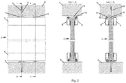
- Fig. 2 the drawing shows the holder according to the invention for a fire panel 2 in three representations, which clarify both the basic structure of the bracket constructive as well as the anchorage in the bottom 3 and the ceiling 4 of the space-limiting structure.
- the two brackets are constructed identically, so that for reasons of simplification, only the holder on the ceiling 4 is described below as an example, but which is identical to the holder on the ground transferable.
- the holder shown for a fire protection pane 2 has two parallel spaced retaining profiles 5, 6 in the form of hollow steel profiles of rectangular cross-section. Between the holding profiles 5 and 6, the fire protection pane 2 is held in a press fit.
- For anchoring to the ceiling 4 distributed over the length of the bracket at least two anchoring tabs 7 are provided at a sufficient distance from each other, which are anchored by means of mounting screws 8 and frame dowels 9 in the ceiling 4.
- each anchoring tab 7 carries a fixing screw 8 and each anchoring tab 7 is attached to the upper in the drawing narrow side of the holding profile 6 by means of a rivet nut 10 and a countersunk screw 11.
- the anchoring tabs 7 extend transversely to the extension direction of the holding profiles 5 and 6, overlap the fire protection pane 2 and form above the holding profile 5 a positioning surface for the mounting of the holding profile 5, as will be described below.
- the strength of the anchoring tab 7 is provided in the described embodiment with 5 mm.
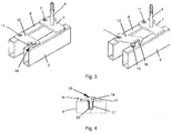
- At least two further tabs are arranged on one of the two holding profiles 5 and 6, which are designed and provided as locking tabs 12.
- the locking tabs 12 are pivotally mounted in the illustrated embodiment as the anchoring tabs 7 on the support section 6 on the upper narrow side via rivet nuts 10 and countersunk screws 11.
- the middle drawing of the Fig. 2 shows a locking tab 12 in the locked position. It is pivotally mounted, extending in the locking position transverse to the course of the holding profiles 5 and 6 and detects a formed on the retaining profile 5 locking counterpart 13, with which the locking tab 12 receives a positive and releasable connection to lock.
- the locking tabs 12 are provided in the embodiment in a thickness of 3 mm to ensure their pivoting in the assembled state of the space-limiting structure. For the same reason, the width of the locking tab 12 is also greater than that of the respective associated narrow side of the hollow profile 5, to allow the application of a tool, for example, even if the locking tab is in the open position on the support section 6.
- Fig. 3 the drawing shows a perspective view of the holder according to the invention in the left figure in the locked position and in the right figure in the open position.
- the locking tab 12 is provided with a recess 14 open in the closing direction, which cooperates with a provided on the holding profile 5 projection 15 as a locking counterpart to the positive, self-locking, but again releasable connection of the two holding profiles 5 and 6 of the holder.
- the recess 14 has to facilitate the actuation process an inlet slope 16, in particular Fig. 4 the drawing is removable.
- Fig. 4 The drawing shows a longitudinal section through the region of the holding profile 5, which is provided with the projection 15 of the locking counterpart.
- a rivet nut 17 is mounted, in which a stepped screw 18 is screwed.
- the stepped screw 18 has under its screw head a clamping shank 19, which via a gradation in a threaded projection 20 smaller diameter passes, so after screwing the stepped screw 18 in the rivet nut 17 of the clamping shaft 19 stands up as locking counterpart and is detected for locking by the recess 14 of the locking tab 12.
- the procedure is that anchored first anchored at the bottom and top 7 retaining profiles 6 in the desired position on the space-limiting structure at the bottom 3 and on the ceiling 4 with dowels 9 and screws 8.
- the anchoring tabs 7 in a rectangular arrangement to the hollow profile form the lower support surface and upper boundary surface for the fire protection panel to be used.
- the fire protection panel 2 is placed on the lower anchoring tabs 7 and then held up and down by superior holding profiles 5 in position.
- the locking tabs 12 are pivoted by means of a simple tool in the locking position and the recesses 14 of the locking tabs 12 are brought into engagement with the clamping shafts 19 of the corresponding stepped screws 18 to produce the desired positive connection between the holding profiles 6 and 5. If a replacement of the fire protection pane is necessary, the connection can be released again, so that the holding profiles 5 can be removed and the fire protection pane can be replaced.
Landscapes
- Engineering & Computer Science (AREA)
- Architecture (AREA)
- Physics & Mathematics (AREA)
- Electromagnetism (AREA)
- Civil Engineering (AREA)
- Structural Engineering (AREA)
- Special Wing (AREA)
- Securing Of Glass Panes Or The Like (AREA)
Description
- Die Erfindung betrifft eine Halterung mit zwei parallel zueinander beabstandeten, mittels mindestens zwei Verankerungslaschen an einer raumbegrenzenden Struktur anbringbaren Halteprofilen für eine Brandschutzscheibe, wobei die Verankerungslaschen mit dem einen Halteprofil verschraubt oder verschweißt sind und als Positioniermittel das zweite Halteprofil erfassen. Die Erfindung betrifft ferner eine Brandschutzverglasung zur Vermeidung des Durchtritts von Feuer und Rauch im Brandfall von einem Raum zu einem anderen mit zumindest einer Brandschutzscheibe, die in einer solchen Halterung fixiert ist.
- Zur Halterung von Brandschutzscheiben in einer Brandschutzverglasung ist es bekannt, jede Brandschutzscheibe auf zwei Verglasungsklötze zu stellen und oben und unten durch je zwei Stahlhohlprofile zu halten, die beidseitig der Brandschutzscheibe angeordnet werden. Für den Anschluss der Stahlhohlprofile an Massivbauteile gibt es unterschiedliche Möglichkeiten. So ist die direkte Befestigung der Profile mittels Schrauben und Metalldübeln an der raumbegrenzenden Struktur bekannt. Als nachteilig wird ferner die Sichtbarkeit der Verschraubung angesehen, die darüber hinaus wegen der die Stahlhohlprofile senkrecht durchgreifenden Verschraubung schwierig zu montieren ist und breite Profile erfordert, um überhaupt ein Werkzeug ansetzen zu können. Dabei ist auch die Positionierung und gleichmäßige Ausrichtung der Stahlhohlprofile in den Fällen schwierig, in denen die raumbegrenzende Struktur uneben ist, so dass aufwendige Justierarbeiten erforderlich sind. Zu berücksichtigen ist dabei, dass zur Herstellung einer raumtrennenden Brandschutzverglasung unter Umständen Raumhöhen bis zu 3,50 Meter abgedeckt werden müssen und folglich die Halterungen der Brandschutzscheiben am Boden und an der Decke hohe mechanische Belastungen auf Grund des Gewichts der Brandschutzscheiben und gegebenenfalls eine hohe mechanische horizontale Stoßbelastung aufnehmen müssen und darüber hinaus den Anforderungen des Brandschutzes genügen müssen.
Alternativ zu der beschriebenen Halterung ist eine verbesserte Halterung für eine Brandschutzscheibe bekannt, bei der die zwei parallel zueinander beabstandeten Halteprofile mittels mindestens zwei Querlaschen in Form von Verankerungslaschen an der raumbegrenzenden Struktur anbringbar sind. Dabei sind die Verankerungslaschen mit dem einem Halteprofil verschraubt oder verschweißt und die Befestigung erfolgt am Massivbauteil durch die Verankerungslaschen mit Metalldübeln und Stahlschrauben.
Um die Aufstellung der Brandschutzscheibe zu ermöglichen, erfolgt die Montage des zweiten Stahlhohlprofils erst nach der Positionierung der Brandschutzscheibe auf den Querlaschen, indem zunächst eine Gewindehülse mit Schraubansatz mit jeder Lasche verschraubt wird. Sodann wird das Stahlhohlprofil auf die Gewindehülsen aufgesetzt, wozu entsprechend große Löcher in dem Stahlhohlprofil ausgebildet sind. Schließlich wird das Stahlhohlprofil mittels einer in jede Gewindehülse einschraubbaren Schraube auf jeder Lasche fixiert. Nachteilig ist dabei, dass die Halterung unterschiedlich ausgebildete Stahlhohlprofile aufweist, dass die Befestigungskonstruktion kompliziert ist, die Montage schwierig ist und Fingerspitzengefühl erfordert. Schließlich ist nachteilig, dass die Fixierschrauben für das zweite Stahlhohlprofil sichtbar sind und damit den ästhetischen Gesamteindruck der Verglasung beeinträchtigen. - Die
DE 92 07 155 U1 (PROMAT GMBH [DE]; 20. August 1992) offenbart eine Halterung gemäß den Merkmalen des Oberbegriffs des Anspruchs 1.
Der Erfindung liegt die Aufgabe zugrunde, unter Meidung oben genannter Nachteile eine Halterung zu entwickeln, die konstruktiv einfach aufgebaut ist, leicht zu montieren und zu demontieren ist und die Nutzung von im Wesentlichen identischen Halteprofilen ermöglicht, die darüber hinaus sehr schmal ausgebildet sind und eine nach der Montage nicht sichtbare Querverbindung miteinander aufweisen.
Die Aufgabe ist erfindungsgemäß dadurch gelöst, dass mindestens zwei weitere als Verriegelungslaschen ausgebildete, verschwenkbar an einem der beiden Halteprofile angeordnete Laschen vorgesehen sind, die mit dem anderen Halteprofil verriegel- und entriegelbar sind. - In Abhängigkeit von den Abmessungen der Brandschutzscheibe befinden sich über die Länge der Halterung in abwechselnder Anordnung verteilt mehrere Verankerungslaschen und mehrere Verriegelungslaschen, um eine sichere Fixierung der Brandschutzscheibe in der Halterung sowie am Boden bzw. der Decke des Raumes sicherzustellen, in welchem die Brandschutzverglasung eingesetzt wird.
- Vorzugsweise sind die Verriegelungslaschen und Verankerungslaschen an dem gleichen Halteprofil befestigt und befinden sich die Verriegelungslaschen in einem Abstand zu den Verankerungslaschen, der größer ist als der äußere Abstand zwischen den Halteprofilen, um ein Verschwenken der Verriegelungslaschen zur Verriegelung oder Entriegelung mit dem anderen Halteprofil zu ermöglichen. Die Halteprofile selbst sind als schmale Metallhohlprofile rechteckigen Querschnitts, insbesondere aus Stahl, ausgestaltet, wobei die Laschen breiter als die jeweils zugehörige Schmalseite der Halteprofile sind. Hierdurch ist es leicht möglich, jede Verriegelungslasche mit einem Werkzeug zu erfassen und in ihre Verriegelungsstellung zu verschwenken oder eine Entriegelung vorzunehmen.
- Die Laschen sind durch in der Verriegelungsstellung im Wesentlichen rechtwinklig an den Halteprofilen angeordnete Metallbleche gebildet, wobei zur Erleichterung der Schwenkbewegung die Stärke der Verriegelungslaschen vorteilhafterweise geringer als die der Verankerungslaschen ist. Die Verriegelung zwischen jeder Verriegelungslasche und dem anderen Halteprofil ist selbsthemmend formschlüssig vorgenommen, wozu vorzugsweise jede Verriegelungslasche mit einer in Schließrichtung offenen Ausnehmung versehen ist, die mit einem an dem anderen Halteprofil angeordneten Vorsprung durch Haftreibung zur Verriegelung zusammenwirkt. Die Ausnehmung kann eine Einlaufschräge aufweisen. Vorzugsweise ist der Vorsprung am anderen Halteprofil in Form einer Stufenschraube ausgebildet, die unter dem Schraubenkopf einen Klemmschaft aufweist, der über eine Abstufung in einen Gewindeansatz geringeren Durchmessers übergeht, welcher mit dem Halteprofil verschraubt ist. In der Verriegelungsstellung der Verriegelungslasche umgreift deren Ausnehmung formschlüssig den Klemmschaft und sichert die Verriegelung über die vorhandene Reibkraft.
- Ein weiterer Gegenstand der vorliegenden Erfindung betrifft eine Brandschutzverglasung zur Vermeidung des Durchtritts von Feuer und Rauch im Brandfall von einem Raum in einen anderen mit zumindest einer Brandschutzscheibe, die in einer erfindungsgemäßen Halterung fixiert ist. Dabei können im Prinzip sämtliche Arten von Brandschutzscheiben eingesetzt werden, wobei solche bevorzugt werden, die zwei mittels eines Randverbunds parallel voneinander beabstandete Glasscheiben aus Einscheiben-Sicherheitsglas aufweisen, bei denen der vom Randverbund eingeschlossene Raum zwischen den Glasscheiben mit einem Brandschutzgel gefüllt ist. Diese zeichnen sich durch gute Brandresistenzen bei gleichzeitig moderatem Gewicht der Verglasung aus.
- Weitere Einzelheiten, Merkmale und Vorteile des Gegenstandes der Erfindung ergeben sich aus der nachfolgenden Beschreibung der zugehörigen Zeichnung. In der Zeichnung zeigt:
- Fig. 1
- eine Brandschutzverglasung, schematisch,
- Fig. 2
- je eine am Boden und an der Decke verankerte erfindungsgemäße Halterung einer Brandschutzscheibe in einer schematischen Seitenansicht, einem Schnitt A-A und einem Schnitt C-C,
- Fig. 3
- die Deckenhalterung der
Fig. 2 perspektivisch in Verriegelungsposition und Entriegelungsposition und - Fig. 4
- einen Längsschnitt durch die Verriegelung
- In
Fig. 1 der Zeichnung ist eine Brandschutzverglasung schematisch dargestellt, mit der Glaswände bis zu einer Höhe von rund 3,50 Metern mit unbegrenzter Länge im Innenbereich von Gebäuden erstellbar sind. Die Brandschutzverglasung 1 ist aus drei nebeneinander in gleicher Ebene angeordneten Brandschutzscheiben 2 aufgebaut, die jeweils aus zwei mittels eines Randverbunds parallel voneinander beabstandeten Glasscheiben aus Einscheiben-Sicherheitsglas bestehen, bei denen der vom Randverbund eingeschlossene Raum zwischen den Glasscheiben mit einem Brandschutzgel gefüllt ist. Die Brandschutzscheiben 2 sind an ihren senkrecht verlaufenden Stoßfugen mit Silikon profilfrei miteinander verbunden. Zur raumbegrenzenden Struktur hin, das heißt mit dem Boden 3 und der Decke 4 des Raumes sind die Brandschutzscheiben 2 jeweils über eine erfindungsgemäße Halterung verankert, die im Detail in denFiguren 2 und3 dargestellt ist. Auch der seitliche vertikale Wandanschluss kann erforderlichenfalls mittels einer erfindungsgemäßen Halterung vorgenommen werden. -
Fig. 2 der Zeichnung zeigt die erfindungsgemäße Halterung für eine Brandschutzscheibe 2 in drei Darstellungen, die sowohl den prinzipiellen Aufbau der Halterung konstruktiv verdeutlichen als auch die Verankerung im Boden 3 und der Decke 4 der raumbegrenzenden Struktur. Die beiden Halterungen sind identisch aufgebaut, so dass nachfolgend aus Gründen der Vereinfachung nur die Halterung an der Decke 4 als Beispiel beschrieben wird, die aber identisch auf die Halterung am Boden übertragbar ist. - Die dargestellte Halterung für eine Brandschutzscheibe 2 weist zwei parallel zueinander beabstandete Halteprofile 5, 6 in Form von Stahlhohlprofilen rechteckigen Querschnitts auf. Zwischen den Halteprofilen 5 und 6 ist die Brandschutzscheibe 2 im Klemmsitz gehalten. Zur Verankerung an der Decke 4 sind über die Länge der Halterung verteilt mindestens zwei Verankerungslaschen 7 in ausreichendem Abstand zueinander vorgesehen, die mit Hilfe von Befestigungsschrauben 8 und Rahmendübeln 9 in der Decke 4 verankert sind. Wie insbesondere dem Schnitt C-C der
Fig. 2 entnehmbar ist, trägt jede Verankerungslasche 7 eine Befestigungsschraube 8 und ist jede Verankerungslasche 7 mit der in der Zeichnung oberen Schmalseite des Halteprofils 6 mittels einer Einnietmutter 10 und einer Senkschraube 11 befestigt. Die Verankerungslaschen 7 verlaufen quer zur Erstreckungsrichtung der Halteprofile 5 und 6, übergreifen die Brandschutzscheibe 2 und bilden oberhalb des Halteprofils 5 eine Positionierfläche für die Montage des Halteprofils 5, wie weiter unten beschrieben wird. Die Stärke der Verankerungslasche 7 ist im beschriebenen Ausführungsbeispiel mit 5 mm vorgesehen. - Um die beiden Halteprofile 5 und 6 miteinander sicher zu verbinden, sind mindestens zwei weitere Laschen an einem der beiden Halteprofile 5 bzw. 6 angeordnet, die als Verriegelungslaschen 12 ausgebildet und vorgesehen sind. Die Verriegelungslaschen 12 sind im dargestellten Ausführungsbeispiel wie die Verankerungslaschen 7 am Halteprofil 6 an dessen oberer Schmalseite über Einnietmuttern 10 und Senkschrauben 11 verschwenkbar befestigt. Die mittlere Zeichnung der
Fig. 2 zeigt eine Verriegelungslasche 12 in Verriegelungsstellung. Sie ist verschwenkbar befestigt, erstreckt sich in der Verriegelungsstellung quer zum Verlauf der Halteprofile 5 und 6 und erfasst ein an dem Halteprofil 5 ausgebildetes Verriegelungsgegenstück 13, mit dem die Verriegelungslasche 12 zur Verriegelung eine formschlüssige und wieder lösbare Verbindung eingeht. Die Verriegelungslaschen 12 sind im Ausführungsbeispiel in einer Stärke von 3 mm vorgesehen, um ihre Verschwenkbarkeit im montierten Zustand an der raumbegrenzenden Struktur zu gewährleisten. Aus dem gleichen Grund ist die Breite der Verriegelungslasche 12 auch größer als die der jeweils zugehörigen Schmalseite des Hohlprofils 5, um das Ansetzen eines Werkzeugs beispielsweise auch dann zu ermöglichen, wenn sich die Verriegelungslasche in Öffnungsstellung am Halteprofil 6 befindet. -
Fig. 3 der Zeichnung zeigt in perspektivischer Darstellung die erfindungsgemäße Halterung in der linken Figur in Verriegelungsstellung und in der rechten Figur in der Öffnungsposition. Insbesondere ist daraus erkennbar, dass die Verriegelungslasche 12 mit einer in Schließrichtung offenen Ausnehmung 14 versehen ist, die mit einem am Halteprofil 5 vorgesehenen Vorsprung 15 als Verriegelungsgegenstück zur formschlüssigen, selbsthemmenden, aber wieder lösbaren Verbindung der beiden Halteprofile 5 und 6 der Halterung miteinander zusammenwirkt. Die Ausnehmung 14 weist zur Erleichterung des Betätigungsvorgangs eine Einlaufschräge 16 auf, die insbesondereFig. 4 der Zeichnung entnehmbar ist.Fig. 4 der Zeichnung zeigt einen Längsschnitt durch den Bereich des Halteprofils 5, der mit dem Vorsprung 15 des Verriegelungsgegenstücks versehen ist. In die obere Schmalseite des Halteprofils 5 ist gegenüberliegend zur Schraubverbindung jeder Verriegelungslasche 12 am Halteprofil 6 eine Einnietmutter 17 angebracht, in welche eine Stufenschraube 18 eingeschraubt ist. Die Stufenschraube 18 weist unter ihrem Schraubenkopf einen Klemmschaft 19 auf, der über eine Abstufung in einen Gewindeansatz 20 geringeren Durchmessers übergeht, sodass nach der Verschraubung der Stufenschraube 18 in der Einnietmutter 17 der Klemmschaft 19 als Verriegelungsgegenstück hochsteht und zur Verriegelung von der Ausnehmung 14 der Verriegelungslasche 12 erfasst wird. - Bei der Erstellung der erfindungsgemäßen Brandschutzverglasung wird so vorgegangen, dass zunächst unten und oben mit Verankerungslaschen 7 fest verschraubte Halteprofile 6 in der gewünschten Position an der raumbegrenzenden Struktur am Boden 3 und an der Decke 4 mit Dübeln 9 und Befestigungsschrauben 8 verankert werden. Die Verankerungslaschen 7 in rechtwinkliger Anordnung zum Hohlprofil bilden die untere Auflagefläche und obere Begrenzungsfläche für die einzusetzende Brandschutzscheibe.
- Im nächsten Montageschritt wird die Brandschutzscheibe 2 auf die unteren Verankerungslaschen 7 aufgesetzt und sodann oben und unten durch vorgesetzte Halteprofile 5 in ihrer Position gehalten. Hierzu werden die Verriegelungslaschen 12 mittels eines einfachen Werkzeugs in die Verriegelungsposition verschwenkt und werden die Ausnehmungen 14 der Verriegelungslaschen 12 in Eingriff mit den Klemmschäften 19 der korrespondierenden Stufenschrauben 18 gebracht, um die gewünschte formschlüssige Verbindung zwischen den Halteprofilen 6 und 5 herzustellen. Wird ein Ersatz der Brandschutzscheibe notwendig, kann die Verbindung wieder gelöst werden, so dass die Halteprofile 5 entfernt werden können und die Brandschutzscheibe ausgewechselt werden kann.
-
- 1
- Brandschutzverglasung
- 2
- Brandschutzscheiben
- 3
- Boden
- 4
- Decke
- 5
- Halteprofil
- 6
- Halteprofil
- 7
- Verankerungslasche
- 8
- Befestigungsschraube
- 9
- Dübel
- 10
- Einnietmutter
- 11
- Senkschraube
- 12
- Verriegelungslasche
- 13
- Verriegelungsgegenstück
- 14
- Ausnehmung
- 15
- Vorsprung
- 16
- Einlaufschräge
- 17
- Einnietmutter
- 18
- Stufenschraube
- 19
- Klemmschaft
- 20
- Gewindeansatz
Claims (12)
- Halterung mit zwei parallel zueinander beabstandeten, mittels mindestens zwei Verankerungslaschen (7) an einer raumbegrenzenden Struktur (3, 4) anbringbaren Halteprofilen (5, 6) für eine Brandschutzscheibe (2), wobei die Verankerungslaschen (7) mit dem einen Halteprofil (6) verschraubt oder verschweißt sind und als Positioniermittel für das zweite Halteprofil (5) dienen, gekennzeichnet durch mindestens zwei weitere als Verriegelungslaschen (12) ausgebildete, verschwenkbar an einem der beiden Halteprofile (5, 6) angeordnete Laschen, die mit dem anderen Halteprofil verriegel- und entriegelbar sind.
- Halterung nach Anspruch 1, dadurch gekennzeichnet, dass über die Länge der Halterung in abwechselnder Anordnung verteilt mehrere Verankerungslaschen (7) und mehrere Verriegelungslaschen (12) vorgesehen sind.
- Halterung nach Anspruch 1 oder 2, dadurch gekennzeichnet, dass die Verriegelungslaschen (12) und die Verankerungslaschen (7) an dem gleichen Halteprofil (6) befestigt sind und dass sich die Verriegelungslaschen (12) in einem Abstand zu den Verankerungslaschen (7) befinden, der größer ist als der äußere Abstand zwischen den Halteprofilen (5, 6).
- Halterung nach einem der Ansprüche 1 bis 3, dadurch gekennzeichnet, dass die Halteprofile (5, 6) als schmale Metallhohlprofile rechteckigen Querschnitts, insbesondere aus Stahl, ausgestaltet sind, und dass die Laschen (7, 12) breiter als die jeweils zugehörigen Schmalseiten der Halteprofile (5, 6) sind.
- Halterung nach einem der Ansprüche 1 bis 4, dadurch gekennzeichnet, dass die Laschen (7, 12) durch in der Verriegelungsstellung im Wesentlichen rechtwinklig an den Halteprofilen (5, 6) angeordnete Metallbleche gebildet sind, wobei die Stärke der Verriegelungslaschen (12) geringer als die der Verankerungslaschen (7) ist.
- Halterung nach einem der Ansprüche 1 bis 5, dadurch gekennzeichnet, dass die Verriegelung zwischen jeder Verriegelungslasche (12) und dem anderen Halteprofil (5) selbsthemmend formschlüssig vorgenommen ist.
- Halterung nach einem der Ansprüche 1 bis 6, dadurch gekennzeichnet, dass die Verriegelungslasche (12) mit einer in Schließrichtung offenen Ausnehmung (14) versehen ist, die mit einem am anderen Halteprofil (5) angeordneten Vorsprung (15) durch Haftreibung zur Verriegelung zusammenwirkt.
- Halterung nach Anspruch 7, dadurch gekennzeichnet, dass die Ausnehmung (14) eine Einlaufschräge (16) aufweist.
- Halterung nach Anspruch 7 oder 8, dadurch gekennzeichnet, dass der Vorsprung am anderen Halteprofil (5) in Form einer Stufenschraube (18) ausgebildet ist, die unter dem Schraubenkopf einen Klemmschaft (19) aufweist, der über eine Abstufung in einen Gewindeansatz (20) geringeren Durchmessers übergeht, welcher mit dem Halteprofil (5) verschraubt ist.
- Brandschutzverglasung (1) zur Vermeidung des Durchtritts von Feuer und Rauch im Brandfall von einem Raum in einen anderen mit zumindest einer Brandschutzscheibe (2) und mit einer Halterung nach einem der Ansprüche 1 bis 9, wobei die Brandschutzscheibe (2) in der Halterung fixiert ist.
- Brandschutzverglasung (1) nach Anspruch 10, dadurch gekennzeichnet, dass die Brandschutzscheibe (2) eine intumeszierende Brandschutzscheibe ist.
- Brandschutzverglasung (1) nach Anspruch 10, dadurch gekennzeichnet, dass die Brandschutzscheibe (2) zwei mittels eines Randverbunds parallel voneinander beabstandete Scheiben aus Einscheiben-Sicherheitsglas aufweist und der vom Randverbund eingeschlossene Raum zwischen den Scheiben mit einem Brandschutzgel gefüllt ist.
Applications Claiming Priority (1)
| Application Number | Priority Date | Filing Date | Title |
|---|---|---|---|
| DE201320104854 DE202013104854U1 (de) | 2013-10-30 | 2013-10-30 | Lösbare Halterung für eine Brandschutzscheibe |
Publications (2)
| Publication Number | Publication Date |
|---|---|
| EP2884035A1 EP2884035A1 (de) | 2015-06-17 |
| EP2884035B1 true EP2884035B1 (de) | 2016-07-13 |
Family
ID=51842385
Family Applications (1)
| Application Number | Title | Priority Date | Filing Date |
|---|---|---|---|
| EP14190697.4A Not-in-force EP2884035B1 (de) | 2013-10-30 | 2014-10-28 | Lösbare halterung für eine brandschutzscheibe |
Country Status (3)
| Country | Link |
|---|---|
| EP (1) | EP2884035B1 (de) |
| DE (1) | DE202013104854U1 (de) |
| PL (1) | PL2884035T3 (de) |
Families Citing this family (3)
| Publication number | Priority date | Publication date | Assignee | Title |
|---|---|---|---|---|
| DE202015105791U1 (de) * | 2015-10-30 | 2017-01-31 | Promat Gmbh | Vorrichtung zur verschiebbaren Halterung eines Profilelements |
| SE2230293A1 (sv) * | 2022-09-15 | 2024-03-16 | Vida Holding Ab | System för förankring av byggelement |
| SE2230292A1 (sv) * | 2022-09-15 | 2024-03-16 | Vida Holding Ab | System för montering av byggelement |
Family Cites Families (6)
| Publication number | Priority date | Publication date | Assignee | Title |
|---|---|---|---|---|
| DE9101452U1 (de) * | 1991-02-08 | 1991-05-02 | PROMAT GmbH, 4030 Ratingen | Brandschutzverglasung |
| DE9207155U1 (de) * | 1992-05-27 | 1992-08-20 | Promat GmbH, 40878 Ratingen | Brandschutzverglasung |
| DE19533273A1 (de) * | 1995-09-08 | 1997-03-13 | Vincenzo Bonanno | Halterung für eine Scheibe in einem Profilrahmen |
| DE19755335C2 (de) * | 1997-12-15 | 2003-12-11 | Koehnlein Gmbh | Glashalterahmen, insbesondere für eine Brandschutzverglasung |
| GB0121968D0 (en) * | 2001-09-11 | 2001-10-31 | Elements And Contracting Ltd C | Improvements in glazing systems |
| DE202009002800U1 (de) * | 2009-02-26 | 2009-05-14 | Promat Gmbh | Brandschutzverglasung |
-
2013
- 2013-10-30 DE DE201320104854 patent/DE202013104854U1/de not_active Expired - Lifetime
-
2014
- 2014-10-28 EP EP14190697.4A patent/EP2884035B1/de not_active Not-in-force
- 2014-10-28 PL PL14190697T patent/PL2884035T3/pl unknown
Also Published As
| Publication number | Publication date |
|---|---|
| PL2884035T3 (pl) | 2017-01-31 |
| EP2884035A1 (de) | 2015-06-17 |
| DE202013104854U1 (de) | 2015-02-02 |
Similar Documents
| Publication | Publication Date | Title |
|---|---|---|
| EP0945577B2 (de) | Verwendung einer Profilschiene zum Abstützen von Fenster- oder Türrahmen | |
| DE102010061139B4 (de) | Wärmebrückenfreier Adapter mit einer Anschlusseinheit zur Befestigung von Gegenständen an Wänden sowie ein Verfahren zur Befestigung von Gegenständen mit einem wärmebrückenfreien Adapter an Wänden | |
| EP3440285B1 (de) | Deckenschalsystem und verfahren zum errichten eines solchen deckenschalsystem | |
| EP2824270A1 (de) | Flächenelement einer Brandschutzverglasung, insbesondere Glastür für Brandschutzzwecke zur Vermeidung des Durchtritts von Feuer und Rauch im Brandfall von einem Raum in einen anderen | |
| EP2322731A2 (de) | Raumhohe Verglasung | |
| EP2884035B1 (de) | Lösbare halterung für eine brandschutzscheibe | |
| EP3365510B1 (de) | Anordnung zur wand-, decken- oder dachbekleidung eines baukörpers | |
| EP1785546A1 (de) | Konsolanker zur Fixierung einer Verblendung an einer Gebäudewand | |
| DE202004002331U1 (de) | Beschlagsystem zum Einbau eines Fensters o.dgl. | |
| EP2405093B1 (de) | Modulare Brandschutzverglasung | |
| EP4114777B1 (de) | Schutzvorrichtung bei montagearbeiten an einer fahrtreppe oder einem fahrsteig | |
| EP3293336B1 (de) | Halteschiene für einen französischen balkon sowie haltevorrichtung und anordnung dafür | |
| DE19737515C2 (de) | Vorrichtung zur Befestigung von Bauteilen an und im Abstand zu einem Tragwerk, insbesondere von Längsprofilen an und im Abstand zu einer Bauwerkswand und dafür geeigneter Abstandhalter | |
| DE102011008315A1 (de) | Konsole für Baugerüste | |
| EP3034714B1 (de) | Spannvorrichtung zur aussteifung von hohlprofilen und verwendung derselben | |
| EP2083127B1 (de) | Anschlusskopf und System zum Erstellen von Aufbauten | |
| DE69932075T2 (de) | Aufzugsschachttuerstruktur | |
| WO2007137805A1 (de) | Konstruktionsanordnung | |
| EP2022903A2 (de) | Befestigungsanordnung und Montageverfahren zum Einbau einer Trägerplatte in eine Durchgangsöffnung zwischen Wänden | |
| EP2949834A1 (de) | Befestigungskonsole für Gerüstbretter, Gerüstbrett und Gerüst | |
| EP1201840B1 (de) | Freistehendes Trennwandsystem | |
| EP0782657B2 (de) | Feuerschutz-tür | |
| DE202020000211U1 (de) | Distanzstück und System zum dauerhaften Befestigen eines Bauteils an wenigstens einem Befestigungspunkt | |
| DE202021106848U1 (de) | Modulares Gittergeländer für einen französischen Balkon | |
| EP4423352A1 (de) | Trägerschiene für ein bekleidungssystem zur einhausung von gerüsten, bekleidungssystem, gerüst sowie verfahren zur einhausung eines gerüsts |
Legal Events
| Date | Code | Title | Description |
|---|---|---|---|
| PUAI | Public reference made under article 153(3) epc to a published international application that has entered the european phase |
Free format text: ORIGINAL CODE: 0009012 |
|
| 17P | Request for examination filed |
Effective date: 20141028 |
|
| AK | Designated contracting states |
Kind code of ref document: A1 Designated state(s): AL AT BE BG CH CY CZ DE DK EE ES FI FR GB GR HR HU IE IS IT LI LT LU LV MC MK MT NL NO PL PT RO RS SE SI SK SM TR |
|
| AX | Request for extension of the european patent |
Extension state: BA ME |
|
| R17P | Request for examination filed (corrected) |
Effective date: 20151217 |
|
| RBV | Designated contracting states (corrected) |
Designated state(s): AL AT BE BG CH CY CZ DE DK EE ES FI FR GB GR HR HU IE IS IT LI LT LU LV MC MK MT NL NO PL PT RO RS SE SI SK SM TR |
|
| GRAP | Despatch of communication of intention to grant a patent |
Free format text: ORIGINAL CODE: EPIDOSNIGR1 |
|
| RIC1 | Information provided on ipc code assigned before grant |
Ipc: E06B 3/54 20060101AFI20160307BHEP Ipc: E06B 3/263 20060101ALI20160307BHEP Ipc: E04B 2/74 20060101ALI20160307BHEP Ipc: E06B 5/16 20060101ALI20160307BHEP |
|
| INTG | Intention to grant announced |
Effective date: 20160331 |
|
| GRAS | Grant fee paid |
Free format text: ORIGINAL CODE: EPIDOSNIGR3 |
|
| GRAA | (expected) grant |
Free format text: ORIGINAL CODE: 0009210 |
|
| AK | Designated contracting states |
Kind code of ref document: B1 Designated state(s): AL AT BE BG CH CY CZ DE DK EE ES FI FR GB GR HR HU IE IS IT LI LT LU LV MC MK MT NL NO PL PT RO RS SE SI SK SM TR |
|
| REG | Reference to a national code |
Ref country code: GB Ref legal event code: FG4D Free format text: NOT ENGLISH |
|
| REG | Reference to a national code |
Ref country code: AT Ref legal event code: REF Ref document number: 812494 Country of ref document: AT Kind code of ref document: T Effective date: 20160715 Ref country code: CH Ref legal event code: EP |
|
| REG | Reference to a national code |
Ref country code: IE Ref legal event code: FG4D Free format text: LANGUAGE OF EP DOCUMENT: GERMAN |
|
| REG | Reference to a national code |
Ref country code: DE Ref legal event code: R096 Ref document number: 502014001103 Country of ref document: DE |
|
| REG | Reference to a national code |
Ref country code: FR Ref legal event code: PLFP Year of fee payment: 3 |
|
| REG | Reference to a national code |
Ref country code: LT Ref legal event code: MG4D |
|
| REG | Reference to a national code |
Ref country code: NL Ref legal event code: MP Effective date: 20160713 |
|
| PG25 | Lapsed in a contracting state [announced via postgrant information from national office to epo] |
Ref country code: RS Free format text: LAPSE BECAUSE OF FAILURE TO SUBMIT A TRANSLATION OF THE DESCRIPTION OR TO PAY THE FEE WITHIN THE PRESCRIBED TIME-LIMIT Effective date: 20160713 Ref country code: NO Free format text: LAPSE BECAUSE OF FAILURE TO SUBMIT A TRANSLATION OF THE DESCRIPTION OR TO PAY THE FEE WITHIN THE PRESCRIBED TIME-LIMIT Effective date: 20161013 Ref country code: IT Free format text: LAPSE BECAUSE OF FAILURE TO SUBMIT A TRANSLATION OF THE DESCRIPTION OR TO PAY THE FEE WITHIN THE PRESCRIBED TIME-LIMIT Effective date: 20160713 Ref country code: IS Free format text: LAPSE BECAUSE OF FAILURE TO SUBMIT A TRANSLATION OF THE DESCRIPTION OR TO PAY THE FEE WITHIN THE PRESCRIBED TIME-LIMIT Effective date: 20161113 Ref country code: HR Free format text: LAPSE BECAUSE OF FAILURE TO SUBMIT A TRANSLATION OF THE DESCRIPTION OR TO PAY THE FEE WITHIN THE PRESCRIBED TIME-LIMIT Effective date: 20160713 Ref country code: NL Free format text: LAPSE BECAUSE OF FAILURE TO SUBMIT A TRANSLATION OF THE DESCRIPTION OR TO PAY THE FEE WITHIN THE PRESCRIBED TIME-LIMIT Effective date: 20160713 Ref country code: FI Free format text: LAPSE BECAUSE OF FAILURE TO SUBMIT A TRANSLATION OF THE DESCRIPTION OR TO PAY THE FEE WITHIN THE PRESCRIBED TIME-LIMIT Effective date: 20160713 Ref country code: LT Free format text: LAPSE BECAUSE OF FAILURE TO SUBMIT A TRANSLATION OF THE DESCRIPTION OR TO PAY THE FEE WITHIN THE PRESCRIBED TIME-LIMIT Effective date: 20160713 |
|
| PG25 | Lapsed in a contracting state [announced via postgrant information from national office to epo] |
Ref country code: SE Free format text: LAPSE BECAUSE OF FAILURE TO SUBMIT A TRANSLATION OF THE DESCRIPTION OR TO PAY THE FEE WITHIN THE PRESCRIBED TIME-LIMIT Effective date: 20160713 Ref country code: PT Free format text: LAPSE BECAUSE OF FAILURE TO SUBMIT A TRANSLATION OF THE DESCRIPTION OR TO PAY THE FEE WITHIN THE PRESCRIBED TIME-LIMIT Effective date: 20161114 Ref country code: LV Free format text: LAPSE BECAUSE OF FAILURE TO SUBMIT A TRANSLATION OF THE DESCRIPTION OR TO PAY THE FEE WITHIN THE PRESCRIBED TIME-LIMIT Effective date: 20160713 Ref country code: ES Free format text: LAPSE BECAUSE OF FAILURE TO SUBMIT A TRANSLATION OF THE DESCRIPTION OR TO PAY THE FEE WITHIN THE PRESCRIBED TIME-LIMIT Effective date: 20160713 Ref country code: GR Free format text: LAPSE BECAUSE OF FAILURE TO SUBMIT A TRANSLATION OF THE DESCRIPTION OR TO PAY THE FEE WITHIN THE PRESCRIBED TIME-LIMIT Effective date: 20161014 |
|
| REG | Reference to a national code |
Ref country code: DE Ref legal event code: R097 Ref document number: 502014001103 Country of ref document: DE |
|
| PG25 | Lapsed in a contracting state [announced via postgrant information from national office to epo] |
Ref country code: EE Free format text: LAPSE BECAUSE OF FAILURE TO SUBMIT A TRANSLATION OF THE DESCRIPTION OR TO PAY THE FEE WITHIN THE PRESCRIBED TIME-LIMIT Effective date: 20160713 Ref country code: RO Free format text: LAPSE BECAUSE OF FAILURE TO SUBMIT A TRANSLATION OF THE DESCRIPTION OR TO PAY THE FEE WITHIN THE PRESCRIBED TIME-LIMIT Effective date: 20160713 |
|
| PLBE | No opposition filed within time limit |
Free format text: ORIGINAL CODE: 0009261 |
|
| STAA | Information on the status of an ep patent application or granted ep patent |
Free format text: STATUS: NO OPPOSITION FILED WITHIN TIME LIMIT |
|
| PG25 | Lapsed in a contracting state [announced via postgrant information from national office to epo] |
Ref country code: DK Free format text: LAPSE BECAUSE OF FAILURE TO SUBMIT A TRANSLATION OF THE DESCRIPTION OR TO PAY THE FEE WITHIN THE PRESCRIBED TIME-LIMIT Effective date: 20160713 Ref country code: SK Free format text: LAPSE BECAUSE OF FAILURE TO SUBMIT A TRANSLATION OF THE DESCRIPTION OR TO PAY THE FEE WITHIN THE PRESCRIBED TIME-LIMIT Effective date: 20160713 Ref country code: BG Free format text: LAPSE BECAUSE OF FAILURE TO SUBMIT A TRANSLATION OF THE DESCRIPTION OR TO PAY THE FEE WITHIN THE PRESCRIBED TIME-LIMIT Effective date: 20161013 Ref country code: SM Free format text: LAPSE BECAUSE OF FAILURE TO SUBMIT A TRANSLATION OF THE DESCRIPTION OR TO PAY THE FEE WITHIN THE PRESCRIBED TIME-LIMIT Effective date: 20160713 |
|
| 26N | No opposition filed |
Effective date: 20170418 |
|
| REG | Reference to a national code |
Ref country code: IE Ref legal event code: MM4A |
|
| PG25 | Lapsed in a contracting state [announced via postgrant information from national office to epo] |
Ref country code: SI Free format text: LAPSE BECAUSE OF FAILURE TO SUBMIT A TRANSLATION OF THE DESCRIPTION OR TO PAY THE FEE WITHIN THE PRESCRIBED TIME-LIMIT Effective date: 20160713 Ref country code: LU Free format text: LAPSE BECAUSE OF NON-PAYMENT OF DUE FEES Effective date: 20161028 |
|
| REG | Reference to a national code |
Ref country code: FR Ref legal event code: PLFP Year of fee payment: 4 |
|
| PG25 | Lapsed in a contracting state [announced via postgrant information from national office to epo] |
Ref country code: IE Free format text: LAPSE BECAUSE OF NON-PAYMENT OF DUE FEES Effective date: 20161028 |
|
| PGFP | Annual fee paid to national office [announced via postgrant information from national office to epo] |
Ref country code: CZ Payment date: 20171012 Year of fee payment: 4 Ref country code: FR Payment date: 20171025 Year of fee payment: 4 Ref country code: DE Payment date: 20171027 Year of fee payment: 4 |
|
| PGFP | Annual fee paid to national office [announced via postgrant information from national office to epo] |
Ref country code: PL Payment date: 20171003 Year of fee payment: 4 Ref country code: BE Payment date: 20171027 Year of fee payment: 4 |
|
| PG25 | Lapsed in a contracting state [announced via postgrant information from national office to epo] |
Ref country code: HU Free format text: LAPSE BECAUSE OF FAILURE TO SUBMIT A TRANSLATION OF THE DESCRIPTION OR TO PAY THE FEE WITHIN THE PRESCRIBED TIME-LIMIT; INVALID AB INITIO Effective date: 20141028 |
|
| REG | Reference to a national code |
Ref country code: CH Ref legal event code: PL |
|
| PG25 | Lapsed in a contracting state [announced via postgrant information from national office to epo] |
Ref country code: MK Free format text: LAPSE BECAUSE OF FAILURE TO SUBMIT A TRANSLATION OF THE DESCRIPTION OR TO PAY THE FEE WITHIN THE PRESCRIBED TIME-LIMIT Effective date: 20160713 Ref country code: CY Free format text: LAPSE BECAUSE OF FAILURE TO SUBMIT A TRANSLATION OF THE DESCRIPTION OR TO PAY THE FEE WITHIN THE PRESCRIBED TIME-LIMIT Effective date: 20160713 Ref country code: MC Free format text: LAPSE BECAUSE OF FAILURE TO SUBMIT A TRANSLATION OF THE DESCRIPTION OR TO PAY THE FEE WITHIN THE PRESCRIBED TIME-LIMIT Effective date: 20160713 Ref country code: MT Free format text: LAPSE BECAUSE OF FAILURE TO SUBMIT A TRANSLATION OF THE DESCRIPTION OR TO PAY THE FEE WITHIN THE PRESCRIBED TIME-LIMIT Effective date: 20160713 |
|
| PG25 | Lapsed in a contracting state [announced via postgrant information from national office to epo] |
Ref country code: LI Free format text: LAPSE BECAUSE OF NON-PAYMENT OF DUE FEES Effective date: 20171031 Ref country code: CH Free format text: LAPSE BECAUSE OF NON-PAYMENT OF DUE FEES Effective date: 20171031 |
|
| PG25 | Lapsed in a contracting state [announced via postgrant information from national office to epo] |
Ref country code: AL Free format text: LAPSE BECAUSE OF FAILURE TO SUBMIT A TRANSLATION OF THE DESCRIPTION OR TO PAY THE FEE WITHIN THE PRESCRIBED TIME-LIMIT Effective date: 20160713 Ref country code: TR Free format text: LAPSE BECAUSE OF FAILURE TO SUBMIT A TRANSLATION OF THE DESCRIPTION OR TO PAY THE FEE WITHIN THE PRESCRIBED TIME-LIMIT Effective date: 20160713 |
|
| REG | Reference to a national code |
Ref country code: DE Ref legal event code: R119 Ref document number: 502014001103 Country of ref document: DE |
|
| GBPC | Gb: european patent ceased through non-payment of renewal fee |
Effective date: 20181028 |
|
| REG | Reference to a national code |
Ref country code: BE Ref legal event code: MM Effective date: 20181031 |
|
| PG25 | Lapsed in a contracting state [announced via postgrant information from national office to epo] |
Ref country code: DE Free format text: LAPSE BECAUSE OF NON-PAYMENT OF DUE FEES Effective date: 20190501 Ref country code: CZ Free format text: LAPSE BECAUSE OF NON-PAYMENT OF DUE FEES Effective date: 20181028 |
|
| PG25 | Lapsed in a contracting state [announced via postgrant information from national office to epo] |
Ref country code: BE Free format text: LAPSE BECAUSE OF NON-PAYMENT OF DUE FEES Effective date: 20181031 Ref country code: FR Free format text: LAPSE BECAUSE OF NON-PAYMENT OF DUE FEES Effective date: 20181031 |
|
| PG25 | Lapsed in a contracting state [announced via postgrant information from national office to epo] |
Ref country code: GB Free format text: LAPSE BECAUSE OF NON-PAYMENT OF DUE FEES Effective date: 20181028 |
|
| PG25 | Lapsed in a contracting state [announced via postgrant information from national office to epo] |
Ref country code: PL Free format text: LAPSE BECAUSE OF NON-PAYMENT OF DUE FEES Effective date: 20181028 |
|
| REG | Reference to a national code |
Ref country code: AT Ref legal event code: MM01 Ref document number: 812494 Country of ref document: AT Kind code of ref document: T Effective date: 20191028 |
|
| PG25 | Lapsed in a contracting state [announced via postgrant information from national office to epo] |
Ref country code: AT Free format text: LAPSE BECAUSE OF NON-PAYMENT OF DUE FEES Effective date: 20191028 |