EP2881526A1 - Planensystem - Google Patents
Planensystem Download PDFInfo
- Publication number
- EP2881526A1 EP2881526A1 EP14003936.3A EP14003936A EP2881526A1 EP 2881526 A1 EP2881526 A1 EP 2881526A1 EP 14003936 A EP14003936 A EP 14003936A EP 2881526 A1 EP2881526 A1 EP 2881526A1
- Authority
- EP
- European Patent Office
- Prior art keywords
- tarpaulin
- tube
- round
- tubes
- tarpaulin system
- Prior art date
- Legal status (The legal status is an assumption and is not a legal conclusion. Google has not performed a legal analysis and makes no representation as to the accuracy of the status listed.)
- Granted
Links
Images


Classifications
-
- E—FIXED CONSTRUCTIONS
- E04—BUILDING
- E04H—BUILDINGS OR LIKE STRUCTURES FOR PARTICULAR PURPOSES; SWIMMING OR SPLASH BATHS OR POOLS; MASTS; FENCING; TENTS OR CANOPIES, IN GENERAL
- E04H15/00—Tents or canopies, in general
- E04H15/32—Parts, components, construction details, accessories, interior equipment, specially adapted for tents, e.g. guy-line equipment, skirts, thresholds
- E04H15/34—Supporting means, e.g. frames
- E04H15/36—Supporting means, e.g. frames arch-shaped type
-
- A—HUMAN NECESSITIES
- A01—AGRICULTURE; FORESTRY; ANIMAL HUSBANDRY; HUNTING; TRAPPING; FISHING
- A01K—ANIMAL HUSBANDRY; AVICULTURE; APICULTURE; PISCICULTURE; FISHING; REARING OR BREEDING ANIMALS, NOT OTHERWISE PROVIDED FOR; NEW BREEDS OF ANIMALS
- A01K1/00—Housing animals; Equipment therefor
-
- A—HUMAN NECESSITIES
- A01—AGRICULTURE; FORESTRY; ANIMAL HUSBANDRY; HUNTING; TRAPPING; FISHING
- A01K—ANIMAL HUSBANDRY; AVICULTURE; APICULTURE; PISCICULTURE; FISHING; REARING OR BREEDING ANIMALS, NOT OTHERWISE PROVIDED FOR; NEW BREEDS OF ANIMALS
- A01K1/00—Housing animals; Equipment therefor
- A01K1/0094—Animal shelters or barns especially adapted for keeping horses
Definitions
- the invention relates to a tarpaulin system, wherein a tarpaulin is tensioned via a carrier system having tubes which are inserted into one another, connectable via screw connections and straps and that the tarpaulin system has at least two cross members, with which the tubes of the carrier system are connectable, wherein the Traverse connector options and screwing options and a ratchet with strap for tensioning the tarpaulin have.
- the plan system according to the invention preferably has a single contiguous tarpaulin, which preferably has on its longitudinal sides below, preferably in each case a pocket which preferably has recesses, wherein in each pocket, preferably over the entire length, a tube is pulled into the pocket.
- the tube which is in the bag, accessible from the outside and can thus preferably be detected by a tension belt, so as to tenter the entire tarpaulin system, the recesses are preferably attached to the two ends of the tarpaulin of the tarpaulin system and in the middle of the tarpaulin system.
- This tarpaulin can be extended on the long sides still down by a side tarpaulin by preferably a tarpaulin fabric, such as preferably a mesh fabric, which is preferably coated, preferably coated with PVC, while the side tarpaulin is attached to the tarpaulin, these side tarpaulin preferably rollable and is fixable by belts in the rolled up state, the side tarp serving to cover side parts, such as grid panels, over which the tarpaulin vault, tarpaulin tunnel is located.
- a side tarpaulin fabric such as preferably a mesh fabric, which is preferably coated, preferably coated with PVC
- these side tarpaulin preferably rollable and is fixable by belts in the rolled up state
- the side tarp serving to cover side parts, such as grid panels, over which the tarpaulin vault, tarpaulin tunnel is located.
- This side tarpaulin also has a longitudinal pocket with recesses at the bottom, through which a tube for tensioning the side tarpaulin can be inserted, as already stated in the tarpaulin above, and can be tensioned by tensioning cables with ratchet tensioning devices, as already stated in the tarpaulin above.
- the tarpaulin forms an overlap, ie a continuation of the tarpaulin over the respective round arch at the entrance and at the exit
- tensioning strap which passes through the pocket of the overlap, preferably a ratchet, which is fastened in each case to a hoe, which can engage around a pipe or a rod or other object on which he Holds to then tension the strap.
- the tarpaulin according to the invention preferably has in the longitudinal center, the apex line 6, ie the points at which the tarpaulin, when folded in the middle of the broad sides along the longitudinal side, the tarpaulin at its two ends, ie on the sides which First sides form when the tarp is stretched in the tarpaulin system, the tarpaulin each having an eye, which preferably fits into a fitting system of the tube, which is located at each vertex of the round arches, wherein the screwing system is formed such that the thread of the screw preferably protrudes vertically upwards, so that the eyelet can reach over the screw.
- the framework which forms the carrier system, over which the tarpaulin is stretched, preferably has transversely, ie at 90 ° to the longitudinal axis of the tarpaulin system two downwardly open struts, preferably rectangular struts or semicircular pipes 10, round arches, preferably two semicircular arches, the one Semicircle form, on, wherein the round arches can consist of one piece or several pieces, which can preferably be inserted into each other.
- These arches are preferably semicircular curved tubes or endeavour Vietnamesefrömig curved hollow rods, ie semicircular tubes 10 form the round arches.
- a basic plan system is preferably 2.4 m, 4.8 m, 7.2 m, etc., ie plus 2.4 m long or 3 m, 6 m, 9 m, etc., ie each plus 3 m long or 3, 6 m, 7.2 m 10.8, etc.
- a standard basic module which is 3 m long and the bow has a height of 1.20 without fasteners to 1.75 m with fasteners can be preferably with other basic modules, each extending 3 m, so that by three basic modules, the base plan system on 9 m length can be extended, with a basic module is the tarpaulin system itself, without being mounted on grid panels.
- a base module has only 2 round arches, an extension preferably has an additional round arch.
- the plan system according to the invention preferably has all 1.5 m, 1.6 m, 1.7 m, 1.8 m, 1.9 m, 2 m, 2.1 m, 2.2 m, 2.3 m, 2, 4 m 2.5 m, 2.6 m, 2.7 m, 2.8 m, 2.9 m, 3 m in length, a round arch on.
- the plan system according to the invention preferably has all 1.5 m, 1.6 m, 1.7 m, 1.8 m, 1.9 m, 2 m, 2.1 m, 2.2 m, 2.3 m, 2 , 4 m 2.5 m, 2.6 m, 2.7 m, 2.8 m, 2.9 m, 3 m in length a transversely to the length standing round arch on or rectangular support system.
- the tarpaulin system is preferably 2.4 m, 3 m, 3.6 m, 4 m, 5 m, 6 m wide, the width being widened by an additional 2.4 m, 3 m, 3.6 m or 4 m can.
- the longitudinal and width elements are preferably lattice panels, such as commercial pasture panels, preferably in the length of 2.4 m, 3 m, 3.6 m, 4 m, 5 m, 6 m and a height of preferably 1.60 cm, so the top horizontal pipe is preferably 1.60 m high.
- a support tube extends at 90 ° to the round arches or equivalent systems, such as the rectangular support system, which may preferably consist of one piece or preferably of several pieces, respectively bump into the round arches and fastened there by means of clamps.
- This support tube thus preferably runs along the longitudinal axis of the tarpaulin system in its center.
- These arches which preferably have semicircular large tubes, are connected by a tube between their vertices, said tube is at 90 ° to the respective semicircle, the round arch.
- the support system preferably further down at least two trusses, which may rest on the ground or on panels, such as preferably commercial grid panels, such as willow panels are attached, the trusses as a basic carrier, so preferably at the bottom of the tarpaulin system on both sides, each a round tube or Have square tube, so preferably are designed as a round tube or square tube, which has at least on the top a receiving device for a round tube or square tube, so preferably even a short round tube or square tube, which is preferably perpendicular to the round tube or square tube, so preferably an inner angle smaller equal to 90 ° to the round tube or square tube forms over which the other round tube or square tube can be pushed, which forms the semicircular arc, over which the tarpaulin is placed and on the underside of the crossbar has fastening elements, preferably a Befe st Trent, preferably by means of a screw enable.
- fastening elements preferably a Befe st Trent,
- These fasteners are preferably metal flat iron, which are at 90 ° to the round tube or square tube and have holes on which preferably the clamps or equivalent fastening systems can be screwed to connect these flat iron and thus the crossbar with support posts or pipes.
- these flat bars each have two pairs of holes, which are spaced from each other, wherein a pair of holes is preferably used for attachment for each clamp.
- a fastener can be attached to two posts on a post.
- These flat bars are preferably welded at 90 ° angle to the base support.
- This base support which is preferably formed by trusses, can also preferably be attached to commercially available lattice panels, which are used, for example, to fence areas.
- the trusses can then be attached to preferably preferably the two uppermost longitudinal tubes of the grid panels on the flat iron with two clamps preferably one above the other. These flat bars are preferably so long that they reach flush over the next longitudinal tube, so that no cord, band or halter can get caught in the ends of the flat iron.
- the trusses can also be fastened directly to posts, which are preferably concreted in, for example to cover a swimming pool embedded in the ground.
- a ratchet is preferably also screwed, with which the tensioning strap can be fastened and tensioned, which preferably engages around the tube through the recess in the pocket the side longitudinal pocket of the tarpaulin lies.
- a ratchet with tensioning strap for tensioning the tarpaulin is preferably located on each flat iron of the traverse.
- a Traverse preferably has on the top two receiving devices for a round tube or square tube, which forms the round arch and on the bottom preferably two fasteners, preferably two flat iron, on.
- a crossbeam for extending the baseplate system can also be done by means of a crossbar, which is inserted into the basic crossbar for extension, in which the two base tubes of the respective trusses are put together and this extension crossbeam can then preferably only on the top preferably a single receiving device for a round tube or square tube, which forms the round arch and on the underside preferably have a fastening element, preferably a flat iron.
- the traverse having a round tube or square tube having at least on the top of a receiving device for a round tube or square tube, which preferably has an angle of less than 90 ° in the direction of the recorded round arch tube to receive a semicircle large arc of tubes.
- the tarpaulin system according to the invention may e.g. in conjunction with commercial grid panels, on the long side, preferably the broadside, form a Mehrzeweckhalle that can serve as a garage, for motor vehicles, boats, equipment of all kinds or as steel for animals such as horses, cows, sheep, etc.
- Another object of the invention is a roof retrofitting system, wherein an inventive plan system for an existing device, preferably a paddock, a swimming pool, a fence system, coupling panels is attached, which is to be roofed, preferably a roof for a fenced by at least two lattice panels surface.
Landscapes
- Life Sciences & Earth Sciences (AREA)
- Environmental Sciences (AREA)
- Zoology (AREA)
- Animal Husbandry (AREA)
- Biodiversity & Conservation Biology (AREA)
- Engineering & Computer Science (AREA)
- Architecture (AREA)
- Animal Behavior & Ethology (AREA)
- Civil Engineering (AREA)
- Structural Engineering (AREA)
- Tents Or Canopies (AREA)
Abstract
Description
- Überdachungen von Pferdeboxen sind bereits im Handel, allerdings handelt es sich dabei um Systeme, die aus einer Vielzahl von Rohren bestehen, die als Quer- und Längsverstrebungen dienen und sehr aufwendig aufgebaut sind, so dass sie sowohl umständlich als auch zeitaufwendig aufzubauen, wie auch zu versenden sind. Des Weiteren sind derartige Überdachungen nach dem Stand der Technik instabil und nicht windstabil.
- Es ist daher Aufgabe der Erfindung den Stand der Technik zu verbessern und insbesondere ein Planensystem zur Verfügung zu stellen, das nach dem Aufbau stabil ist und leicht aufzubauen und zu versenden ist.
- Gegenstand der Erfindung ist ein Planensystem, wobei eine Plane über ein Trägersystem spannbar ist, das Rohre aufweist, die ineinander gesteckt, über Verschraubungen und Spanngurte verbindbar sind und dass das Planensystem mindestens zwei Traversen aufweist, mit denen die Rohre des Trägersystem verbindbar sind, wobei die Traverse Steckverbindungsmöglichkeiten und Verschraubungsmöglichkeiten sowie eine Ratsche mit Spanngurt zum Spannen der Plane aufweisen.
- Das erfindungsgemäße Plannensystem weist vorzugsweise eine einzige zusammenhängende Plane auf, die vorzugsweise an ihren Längsseiten unten, vorzugsweise jeweils eine Tasche aufweist, die vorzugsweise Aussparungen aufweist, wobei in jeder Tasche, vorzugsweise über die gesamte Länge, ein Rohr jeweils in die Tasche eingezogen ist. An den Aussparungen in der Taschen ist das Rohr, das in der Tasche liegt, von Außen zugänglich und kann so vorzugsweise von einem Spanngurt erfaßt werden, um so das gesamte Planensystem abzuspannen, wobei die Aussparungen vorzugsweise an den beiden Enden der Planen des Planensystems und in der Mitte des Planensystems angebracht sind. Diese Plane kann an den Längsseiten noch nach unten durch eine Seitenplane verlängert werden, indem vorzugsweise ein Planengewebe, wie vorzugsweise ein Gittergewebe, das vorzugsweise beschichtet ist, vorzugsweise mit PVC beschichtet ist, dabei ist die Seitenplane an der Plane angebracht, wobei diese Seitenplane vorzugsweise aufrollbar und durch Riemen im aufgerollten Zustand fixierbar ist, wobei die Seitenplane dazu dient Seitenteile, wie Gitterpanele abzudecken, über denen sich das Planengewölbe, Planentunnel befindet. Diese Seitenplane weist auch eine Längstasche mit Aussparungen an der Unterseite auf, durch die ein Rohr zum Abspannen der Seitenplane eingeführt werden kann, wie bei der Plane oben bereits ausgeführt, und durch Spannseile mit Ratschenabspannvorrichtungen abgespannt werden kann, wie bei der Plane oben bereits ausgeführt.
- An den beiden Enden, also am Eingang und Ausgang des Planensystems, das vorzugsweise ein Tunnel, also die Form eines Tunnels bildet, bildet die Plane eine Überlappung, also eine Fortsetzung der Plane über den jeweiligen Rundbogen am Eingang und am Ausgang, aus, wobei die Überlappung an ihrem äußersten Ende eine, vorzugsweise um die gesamte Überlappung, laufende Tasche aufweist, wobei vorzugsweise in den beiden Taschen ein Spanngurt durchgezogen werden kann, um das Planensystem am Eingang und am Ausgang vorzugsweise über die gesamte Überlappung abzuspannen. Dies geschieht vorzugsweise in dem sich an den beiden Enden des Spanngurtes, der durch die Tasche der Überlappung läuft, vorzugsweise eine Ratsche befindet, die jeweils an einem Hacken befestigt ist, der um ein Rohr oder eine Stange oder sonstigen Gegenstand greifen kann, an dem er Halt findet, um sodann den Spanngurt abzuspannen.
- Die erfindungsgemäße Plane weist vorzugsweise in der Längsmitte, der Scheitellinie 6, also den Stellen, an denen die Plane, wenn sie in der Mitte der Breitseiten entlang der Längsseite gefaltet wird, weist die Plane an ihren beiden Enden, also an den Seiten, die die Firstseiten bilden werden, wenn die Plane im Planensystem aufgespannt ist, weist die Plane jeweils eine Öse auf, die vorzugsweise in ein Verschraubungssystem des Rohres passt, das sich jeweils am Scheitelpunkten der Rundbögen befindet, wobei das Verschraubungssystem derart ausgebildet ist, dass das Gewinde der Schraube vorzugsweise senkrecht nach oben ragt, so dass die Öse über die Schraube greifen kann.
- Das Gerüst, das das Trägersystem bildet, über das die Plane gespannt wird, weist vorzugsweise querstehend, also in 90° zur Längsachse des Planensystems zwei nach unten offene Verstrebungen, vorzugsweise rechteckige Verstrebungen oder Halbkreis großen Rohre 10, Rundbögen, vorzugsweise zwei Rundbögen, die einen Halbkreis bilden, auf, wobei die Rundbögen aus einem Stück oder mehreren Stücken bestehen können, die vorzugsweise ineinander gesteckt werden können. Diese Rundbögen sind vorzugsweise halbkreisförmig gebogene Rohre oder halbkreisfrömig gebogene Hohlstangen, also halbkreis großen Rohre 10 bilden die Rundbögen. Diese Rundbögen sind an den beiden Enden des tunnelförmigen Planensystems angebracht, bei einem längeren Planensystem können auch noch zusätzliche Rundbögen in der Mitte des tunnelförmigen Planensystems angeordnet werden. Ein Basisplanensystem ist vorzugsweise 2,4 m, 4,8 m, 7,2 m usw., also jeweils plus 2,4 m lang oder 3 m, 6 m, 9 m usw., also jeweils plus 3 m lang oder 3,6 m, 7,2 m 10,8 usw. jeweils plus 3,6 m lang oder 4 m, 8 m, 12 m usw., also jeweils plus 4 m und 2,4 m, 3 m, 3,6 m, 4 m, 5 m, 6 m breit, wobei die Länge und Breite des Planensystems vorzugsweise durch Elemente in Form von Gitterpanelen, wie handelsüblichen Weidepanelen vorgegeben wird, die vorzugsweise 2,4 m, 3 m, 3,6 m, 4 m lang sind und deren oberstes horizontales Rohr vorzugsweise 1,60 m hoch ist, auf die das erfindungsgemäße Planensystems montiert wird. Ein übliches Grundmodul, das 3 m lang ist und der Bogen eine Höhe von 1,20 ohne Befestigungselemente bis 1,75 m mit Befestigungselementen aufweist, läßt sich vorzugsweise mit weiteren Grundmodulen, um jeweils 3 m verlängern, so dass durch drei Grundmodule das Basisplanensystem auf 9 m Länge verlängert werden kann, wobei ein Grundmodul das Planensystem für sich ist, ohne auf Gitterpanelen montiert zu sein. Vorzugsweise weist ein Grundmodul nur 2 Rundbögen auf, eine Verlängerung weist vorzugsweise einen zusätzlichen Rundbogen auf. Vorzugsweise weist das erfindungsgemäße Planensystem alle 1,5 m, 1,6 m, 1,7 m, 1,8 m 1,9 m, 2 m, 2,1 m, 2,2 m, 2,3 m, 2,4 m 2,5 m, 2,6 m, 2,7 m, 2,8 m, 2,9 m, 3 m Länge einen Rundbogen auf.
- Statt der Rundbögen könnte als Trägersystem auch ein rechteckiges Trägersystem verwendet werden, das ein gleichseitiges oder nicht gleichseitiges, nach unten offenes, Rechteck bildet. Vorzugsweise weist das erfindungsgemäße Planensystem alle 1,5 m, 1,6 m, 1,7 m, 1,8 m, 1,9 m, 2 m, 2,1 m, 2,2 m, 2,3 m, 2,4 m 2,5 m, 2,6 m, 2,7 m, 2,8 m, 2,9 m, 3 m Länge einen quer zur Länge stehenden Rundbogen auf oder rechteckiges Trägersystem auf.
- Das Planensystem ist vorzugsweise 2,4 m, 3 m, 3,6 m, 4 m, 5 m, 6 m breit, wobei die Breite jeweils um weitere 2,4 m, 3 m, 3,6 m oder 4 m verbreitert werden kann.
- Die Längs- und Breitenelemente sind vorzugsweise Gitterpanele, wie handelsübliche Weidepanele, vorzugsweise in der Länge 2,4 m, 3 m, 3,6 m, 4 m, 5m, 6 m und einer Höhe von vorzugsweise 1,60 cm , also deren oberstes horizontales Rohr vorzugsweise 1,60 m hoch ist.
- In der Mitte des Trägersystems im Scheitelpunkt, also an der obersten Stelle des Trägersystems, verläuft ein Trägerrohr im 90° Winkel zu den Rundbögen oder äquivalenten Systemen, wie dem rechteckigen Trägersystem, das vorzugsweise aus einem Stück oder bevorzugt aus mehreren Stücken bestehen kann, die jeweils an die Rundbögen stoßen und dort mittels Schellen befestigt werden. Dieses Trägerrohr verläuft also vorzugsweise längs der Längsachse des Planensystems in dessen Mitte. Diese Rundbögen, die vorzugsweise Halbkreis große Rohre aufweisen, sind über ein Rohr zwischen ihren Scheitelpunkten verbunden, wobei dieses Rohr im 90° Winkel zum jeweiligen Halbkreis, dem Rundbogen steht.
- Das Trägersystem weist vorzugsweise unten noch zumindest zwei Traversen auf, die auf dem Boden aufliegen können oder an Panele, wie vorzugsweise handelsüblichen Gitterpanelen, wie Weidepanelen befestigt werden, wobei die Traversen als Grundträger, also vorzugsweise unten am Planensystem auf beiden Seiten, jeweils ein Rundrohr oder Vierkantrohr aufweisen, also vorzugsweise als Rundrohr oder Vierkantrohr ausgebildet sind, das zumindest auf der Oberseite eine Aufnahmevorrichtung für ein Rundrohr oder Vierkantrohr aufweist, also vorzugsweise selbst ein kurzes Rundrohr oder Vierkantrohr, das vorzugsweise senkrecht auf dem Rundrohr oder Vierkantrohr steht, also vorzugsweise einen Innenwinkel kleiner gleich 90° zum Rundrohr oder Vierkantrohr bildet, über das das andere Rundrohr oder Vierkantrohr geschoben werden kann, das den halbkreisförmigen Rundbogen bildet, über den die Plane gelegt wird und auf der Unterseite der Traverse Befestigungselemente aufweist, die vorzugsweise eine Befestigung, vorzugsweise mittels einer Verschraubung ermöglichen. Diese Befestigungselemente sind vorzugsweise Metallflacheisen, die im 90° Winkel zum Rundrohr oder Vierkantrohr stehen und Bohrungen aufweisen, an denen vorzugsweise die Schellen oder äquivalenten Befestigungssysteme geschraubt werden können, um diese Flacheisen und damit die Traverse mit Stützpfählen oder Rohren zu verbinden. Vorzugsweise weisen diese Flacheisen jeweils zwei Bohrungspaare auf, die von einander beabstandet sind, wobei ein Bohrungspaare vorzugsweise zur Befestigung für jeweils eine Schelle dient. Somit kann ein Befestigungselement an zwei Stellen an einem Pfosten befestigt werden. Diese Flacheisen werden vorzugsweise im 90 ° Winkel an den Grundträger geschweißt. Dieser Grundträger, der vorzugsweise durch Traversen gebildet wird, kann auch vorzugsweise an handelsübliche Gitterpanelen befestigt werden, die z.B. verwendet werden, um Flächen einzuzäunen. Die Traversen können dann an vorzugsweise den beiden obersten Längsrohren der Gitterpanele jeweils an den Flacheisen mit jeweils zwei Schellen vorzugsweise übereinander befestigt werden. Diese Flacheisen sind vorzugsweise so lang, dass sie über das nächste Längsrohr bündig greifen, so dass sich in den Enden der Flacheisen keine Schnur, Band oder Halfter verfangen kann.
- Die Traversen können auch direkt mit Pfosten, die vorzugsweise einbetoniert sind, befestigt werden, zum Beispiel um ein im Boden eingelassenes Schwimmbad zu überdachen.
- An einer Bohrungen in dem Flacheisen, an dem eine Schelle über eine Schraubverbindung befestigt sein kann, wird auch vorzugsweise eine Ratsche festgeschraubt, mit der der Spanngurt befestigt und gespannt werden kann, der vorzugsweise durch die Aussparung in der Tasche um das Rohr greift, das in der seitlichen Längstasche der Plane liegt. So befindet sich an jedem Flacheisen der Traverse vorzugsweise eine Ratsche mit Spanngurt zum Spannen der Plane. Eine Traverse weist vorzugsweise auf der Oberseite zwei Aufnahmevorrichtungen für ein Rundrohr oder Vierkantrohr auf, das den Rundbogen bildet und auf der Unterseite vorzugsweise zwei Befestigungselemente, bevorzugt zwei Flacheisen, auf.
- Eine Traverse zur Verlängerung des Basisplanensystem kann auch mittels einer Traverse geschehen, die in die Grundtraverse zur Verlängerung gesteckt wird, in dem die beiden Grundrohre der jeweiligen Traversen zusammengesteckt werden und diese Verlängerungstraverse kann dann auch nur vorzugsweise auf der Oberseite vorzugsweise eine einzige Aufnahmevorrichtung für ein Rundrohr oder Vierkantrohr aufweisen, das den Rundbogen bildet und auf der Unterseite vorzugsweise ein Befestigungselement, bevorzugt ein Flacheisen aufweisen.
- Bevorzugt weist die Traverse, die ein Rundrohr oder Vierkantrohr aufweist, das zumindest auf der Oberseite eine Aufnahmevorrichtung für ein Rundrohr oder Vierkantrohr aufweist, das vorzugsweise einen Winkel kleiner 90° in Richtung des aufgenommenen Rundbogenrohrs aufweist, um einen Halbkreis großen Bogen aus Rohren aufzunehmen.
- Das erfindungsgemäße Planensystem kann z.B. in Verbindung mit handelsüblichen Gitterpanelen, an der Längsseite,vorzugsweise der Breitseite, eine Mehrzeweckhalle bilden, die als Garage, für Kraftfahrzeuge, Boote, Geräte aller Art oder auch als Stahl für Tiere, wie Pferde, Kühe, Schafe etc. dienen kann.
- Ein weitere Gegenstand der Erfindung ist ein Überdachungsnachrüstsystem, wobei ein erfindungsgemäßes Planensystem für eine vorhandene Vorrichtung, vorzugsweise eine Pferdekoppel, ein Schwimmbecken, ein Zaunsystem, Koppelpaneele befestigt ist, die überdacht werden soll, bevorzugt eine Überdachung für eine durch zumindest zwei Gitterpaneelen eingezäunte Fläche dient.
-
-
Figur 1
Figur 1 zeigt die erfindungsgemäße Plane in Draufsicht. An der Längsseite der Plane sind die Langstaschen 1 mit den Aussparungen 2 zu sehen, durch die das Rohr, das in jeder Längstasche liegen wird, zu umfassen. An diese Plane ist eine Seitenplane 3 angebracht, die auch eine Längstasche 4 mit Aussparungen 5 an der Unterseite aufweist, durch die ein Rohr zum Abspannen der Seitenplane eingeführt werden kann. In der Mitte der Plane ist die Scheitellinie 6 zu sehen und die Ösen 7, die über das Gewinde der Befestigungsschraube gelegt werden, in denen das Befestigungsrohr über Schellen an den Rundbögen befestigt wird. Vorne und hinten an der Plane sind die Überlappungen 8 zu sehen, die über den vorderen und hinteren Rundbogen überlappend gelegt und durch die jeweils ein Spanngurt durch die Öffnungen 9 in einer Tasche der Überlappung, die sich über die gesamte Länge der Überlappung erstreckt, gezogen werden kann. -
Figur 2
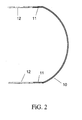
Figur 2 zeigt einen der zumindest zwei Rundbögen 10 als Querschnitt. Der Rundbogen 10 ist über die Traverse 11 auf einem Gitterpaneel 12 befestigt. -
Figur 3
InFigur 3 ist die erfindungsgemäße Traverse 11 mit dem Grundrohr 13 und den Aufnahmevorrichtungen 14, in die die Rundbögen gesteckt werden können, wobei diese vorzugsweise einen Winkel kleiner 90 ° zum Gruncrohr aufweisen, um der Krümmung des Rundbogens Rechnung zu tragen. Des Weiteren steht nach unten zumindest ein Flacheisen 15 im 90 ° Winkel zum Grundrohr, an dem die Schellen und vorzugsweise die Ratsche des Spanngurtes befestigt werden können, dazu sind Bohrungen 16 vorgesehen, an denen Schraubverbindungen angebracht werden können. -
Figur 4
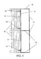
InFigur 4 wird eine Seitenansicht der Längsseite des Trägersystems gezeigt. Dabei sind zwei Gitterpanele 16 unten zu sehen, an denen die zwei Traversen 11, mit zwei Flacheisen 15, und 15, mit einem einzigen Flacheisen 15, zu sehen ist, die über die Flacheisen 15 mittels Schellen (nicht gezeigt) befestigt an den Gitterpanelen befestigt sind. An der Traverse sind die Rundbögen 10 über die Aufnahmevorrichtungen an den Traversen 11 angebracht, oben am First ist Rohr 17 zu sehen, das die Rundbögen 10 stabilisiert, wobei das Rohr 17 vorzugsweise und über Schellenverbindungen mit den Rundbögen 10 verbunden ist.
Claims (9)
- Planensystem, wobei eine Plane über ein Trägersystem spannbar ist, das Rohre aufweist, die ineinander gesteckt, über Verschraubungen und Spanngurte verbindbar sind und das Planensystem mindestens zwei Traversen 11 aufweist, mit denen die Rohre des Gerüsts verbindbar sind, wobei die Traverse Steckverbindungsmöglichkeiten und Verschraubungsmöglichkeiten sowie eine Ratsche mit Spanngurt zum Spannen der Plane aufweisen.
- Planensystem nach Anspruch 1, dadurch gekennzeichnet, dass das Trägersystem, über das die Plane gespannt wird, zumindest an beiden Enden zwei nach unten offene Verstrebungen, vorzugsweise rechteckige Verstrebungen oder Halbkreis großen Rohre 10, Rundbögen, aufweist, die über ein Rohr 17 zwischen ihren Scheitelpunkten verbunden sind, wobei dieses Rohr vorzugsweise im 90° Winkel zum jeweiligen Rundbogen steht.
- Planensystem nach einem oder mehreren der Ansprüche 1 bis 2, dadurch gekennzeichnet, dass die Traverse ein Rundrohr oder Vierkantrohr aufweist, das zumindest auf der Oberseite eine Aufnahmevorrichtung für ein Rundrohr oder Vierkantrohr aufweist und auf der. Unterseite Befestigungselemete aufweist, die eine Verschraubung ermöglichen.
- Planensystem nach einem oder mehreren der Ansprüche 1 bis 3, dadurch gekennzeichnet, dass die Traverse ein Rundrohr oder Vierkantrohr als Grundrohr aufweist, das zumindest auf der Oberseite eine Aufnahmevorrichtung für ein Rundrohr oder Vierkantrohr aufweist, das einen Winkel kleiner 90° in Richtung Rundbogen 10 aufweist, um einen Halbkreis großen Bogen aus Rohre aufzunehmen.
- Planensystem nach einem oder mehreren der Ansprüche 1 bis 4, dadurch gekennzeichnet, dass der Spanngurt mit einer Ratsche gespannt ist, die an der Traverse 11 befestigt ist.
- Planensystem nach einem oder mehreren der Ansprüche 1 bis 5, dadurch gekennzeichnet, dass die Plane an ihren beiden Firstseiten jeweils eine Öse 7 aufweist, die vorzugsweise in ein Verschraubungssystem des Rohres passt, das sich am Scheitelpunkten zwischen den Rundbögen befindet.
- Planensystem nach einem oder mehreren der Ansprüche 1 bis 6, dadurch gekennzeichnet, dass die Plane jeweils an beiden Seiten längs eine Tasche laufweist, in der sich jeweils ein Rohr befindet, an dem der Spanngurt eingreifen kann, um so das Planensystem an der Traverse 11 zu verspannen.
- Planensystem nach einem oder mehreren der Ansprüche 1 bis 7, dadurch gekennzeichnet, dass, an den beiden Enden, also am Eingang und Ausgang des Planensystems, die Plane eine Überlappung 3, also eine Fortsetzung der Plane über den jeweiligen Rundbogen am Eingang und am Ausgang bildet, wobei die Überlappung 3 eine Tasche 4 aufweist, wobei vorzugsweise in den beiden Taschen 4 über die gesamte Taschenlänge ein Spanngurt durchgezogen werden kann, um das Planensystem am Eingang und am Ausgang abzuspannen.
- Überdachungsnachrüstsystem, dadurch gekennzeichet, dass ein Planensystem nach einem oder mehreren der Ansprüche 1 bis 8 für eine vorhandene Vorrichtung, vorzugsweise eine Pferdekoppel, ein Schwimmbecken, ein Zaunsystem, Koppelpanelle befestigt ist, die überdacht werden soll.
Priority Applications (1)
| Application Number | Priority Date | Filing Date | Title |
|---|---|---|---|
| EP14003936.3A EP2881526B1 (de) | 2013-12-09 | 2014-11-11 | Planensystem |
Applications Claiming Priority (3)
| Application Number | Priority Date | Filing Date | Title |
|---|---|---|---|
| DE201320009884 DE202013009884U1 (de) | 2013-12-09 | 2013-12-09 | Planensystem |
| EP14003704 | 2014-11-04 | ||
| EP14003936.3A EP2881526B1 (de) | 2013-12-09 | 2014-11-11 | Planensystem |
Publications (2)
| Publication Number | Publication Date |
|---|---|
| EP2881526A1 true EP2881526A1 (de) | 2015-06-10 |
| EP2881526B1 EP2881526B1 (de) | 2019-09-04 |
Family
ID=52020885
Family Applications (1)
| Application Number | Title | Priority Date | Filing Date |
|---|---|---|---|
| EP14003936.3A Active EP2881526B1 (de) | 2013-12-09 | 2014-11-11 | Planensystem |
Country Status (1)
| Country | Link |
|---|---|
| EP (1) | EP2881526B1 (de) |
Citations (5)
| Publication number | Priority date | Publication date | Assignee | Title |
|---|---|---|---|---|
| US3863659A (en) * | 1974-03-19 | 1975-02-04 | Robert E Gillis | Shelter structure |
| EP0504074A1 (de) * | 1991-03-08 | 1992-09-16 | Jacques Petiard | Halle, bestehend aus einem Metallgerüst und einer Dachhaut |
| US6073587A (en) * | 1998-12-10 | 2000-06-13 | Hill; Dale L. | Modular animal shelter |
| GB2382594A (en) * | 2001-11-29 | 2003-06-04 | Loddon Ltd | Portable loose boxes or stalls with fabric roof |
| US20100126545A1 (en) * | 2008-11-25 | 2010-05-27 | Bullivant Todd J | Rapidly deployable military vehicle repair facility |
-
2014
- 2014-11-11 EP EP14003936.3A patent/EP2881526B1/de active Active
Patent Citations (5)
| Publication number | Priority date | Publication date | Assignee | Title |
|---|---|---|---|---|
| US3863659A (en) * | 1974-03-19 | 1975-02-04 | Robert E Gillis | Shelter structure |
| EP0504074A1 (de) * | 1991-03-08 | 1992-09-16 | Jacques Petiard | Halle, bestehend aus einem Metallgerüst und einer Dachhaut |
| US6073587A (en) * | 1998-12-10 | 2000-06-13 | Hill; Dale L. | Modular animal shelter |
| GB2382594A (en) * | 2001-11-29 | 2003-06-04 | Loddon Ltd | Portable loose boxes or stalls with fabric roof |
| US20100126545A1 (en) * | 2008-11-25 | 2010-05-27 | Bullivant Todd J | Rapidly deployable military vehicle repair facility |
Also Published As
| Publication number | Publication date |
|---|---|
| EP2881526B1 (de) | 2019-09-04 |
Similar Documents
| Publication | Publication Date | Title |
|---|---|---|
| DE2519841A1 (de) | Vorfabriziertes gebaeude | |
| DE102009047383A1 (de) | Wetterschutzüberdachung für Pflanzenkulturen | |
| DE202015106331U1 (de) | Transportable Zaunabstützvorrichtung | |
| DE102021210853A1 (de) | Zusatzcampingraum | |
| DE69415801T2 (de) | Not-schutzhaus | |
| EP3372754B1 (de) | Vorzelt für ein fahrzeug, insbesondere für einen wohnwagen oder ein wohnmobil | |
| DE202017000274U1 (de) | Weideunterstand | |
| EP2881526B1 (de) | Planensystem | |
| DE202014106083U1 (de) | Schnell-Montage-Wetterschutzdach | |
| EP2910110B1 (de) | Überdachung für reihenförmig angeordnete Pflanzenkulturen | |
| DE69706497T2 (de) | Hagelschutz | |
| DE102013020218B3 (de) | Planensystem | |
| DE202013009884U1 (de) | Planensystem | |
| EP3179014B1 (de) | Fachwerkdachbinder mit eckteil und eine diesen verwendende dachanordnung | |
| DE202015106114U1 (de) | Mobile Trampolinvorrichtung | |
| DE102014014311A1 (de) | Mast mit Abspannung | |
| DE102016104811B4 (de) | Vorrichtung zur Befestigung von Flächenelementen an Wetterschutzdächern | |
| DE20109216U1 (de) | Dachrandsicherung für Flachdächer | |
| AT303588B (de) | Einrichtung zum vorübergehenden Abdecken von großen Plätzen, insbesondere Sportplätzen | |
| DE20212550U1 (de) | Wohnwagen-Vorzelt | |
| DE8911820U1 (de) | Spiel-, Turn- und Klettergerät | |
| DE3421742A1 (de) | Dachkonstruktion fuer baustellen | |
| DE202020106298U1 (de) | Zelt für den Anbau an ein Gestell | |
| DE202010014225U1 (de) | Longierzirkel mit einer Umzäunung | |
| DE20203750U1 (de) | Wetterschutzvorrichtung zur Befestigung an einem aus Holmen bestehenden Baugerüst |
Legal Events
| Date | Code | Title | Description |
|---|---|---|---|
| PUAI | Public reference made under article 153(3) epc to a published international application that has entered the european phase |
Free format text: ORIGINAL CODE: 0009012 |
|
| 17P | Request for examination filed |
Effective date: 20141111 |
|
| AK | Designated contracting states |
Kind code of ref document: A1 Designated state(s): AL AT BE BG CH CY CZ DE DK EE ES FI FR GB GR HR HU IE IS IT LI LT LU LV MC MK MT NL NO PL PT RO RS SE SI SK SM TR |
|
| AX | Request for extension of the european patent |
Extension state: BA ME |
|
| R17P | Request for examination filed (corrected) |
Effective date: 20151203 |
|
| RBV | Designated contracting states (corrected) |
Designated state(s): AL AT BE BG CH CY CZ DE DK EE ES FI FR GB GR HR HU IE IS IT LI LT LU LV MC MK MT NL NO PL PT RO RS SE SI SK SM TR |
|
| STAA | Information on the status of an ep patent application or granted ep patent |
Free format text: STATUS: EXAMINATION IS IN PROGRESS |
|
| 17Q | First examination report despatched |
Effective date: 20161202 |
|
| GRAP | Despatch of communication of intention to grant a patent |
Free format text: ORIGINAL CODE: EPIDOSNIGR1 |
|
| STAA | Information on the status of an ep patent application or granted ep patent |
Free format text: STATUS: GRANT OF PATENT IS INTENDED |
|
| INTG | Intention to grant announced |
Effective date: 20190226 |
|
| GRAS | Grant fee paid |
Free format text: ORIGINAL CODE: EPIDOSNIGR3 |
|
| GRAA | (expected) grant |
Free format text: ORIGINAL CODE: 0009210 |
|
| STAA | Information on the status of an ep patent application or granted ep patent |
Free format text: STATUS: THE PATENT HAS BEEN GRANTED |
|
| AK | Designated contracting states |
Kind code of ref document: B1 Designated state(s): AL AT BE BG CH CY CZ DE DK EE ES FI FR GB GR HR HU IE IS IT LI LT LU LV MC MK MT NL NO PL PT RO RS SE SI SK SM TR |
|
| RAP1 | Party data changed (applicant data changed or rights of an application transferred) |
Owner name: JOPE GMBH |
|
| REG | Reference to a national code |
Ref country code: GB Ref legal event code: FG4D Free format text: NOT ENGLISH |
|
| RIN1 | Information on inventor provided before grant (corrected) |
Inventor name: RATKA, JOHANN |
|
| REG | Reference to a national code |
Ref country code: CH Ref legal event code: EP |
|
| REG | Reference to a national code |
Ref country code: AT Ref legal event code: REF Ref document number: 1175551 Country of ref document: AT Kind code of ref document: T Effective date: 20190915 |
|
| REG | Reference to a national code |
Ref country code: DE Ref legal event code: R096 Ref document number: 502014012545 Country of ref document: DE |
|
| REG | Reference to a national code |
Ref country code: IE Ref legal event code: FG4D Free format text: LANGUAGE OF EP DOCUMENT: GERMAN |
|
| REG | Reference to a national code |
Ref country code: NL Ref legal event code: MP Effective date: 20190904 |
|
| REG | Reference to a national code |
Ref country code: LT Ref legal event code: MG4D |
|
| PG25 | Lapsed in a contracting state [announced via postgrant information from national office to epo] |
Ref country code: FI Free format text: LAPSE BECAUSE OF FAILURE TO SUBMIT A TRANSLATION OF THE DESCRIPTION OR TO PAY THE FEE WITHIN THE PRESCRIBED TIME-LIMIT Effective date: 20190904 Ref country code: HR Free format text: LAPSE BECAUSE OF FAILURE TO SUBMIT A TRANSLATION OF THE DESCRIPTION OR TO PAY THE FEE WITHIN THE PRESCRIBED TIME-LIMIT Effective date: 20190904 Ref country code: SE Free format text: LAPSE BECAUSE OF FAILURE TO SUBMIT A TRANSLATION OF THE DESCRIPTION OR TO PAY THE FEE WITHIN THE PRESCRIBED TIME-LIMIT Effective date: 20190904 Ref country code: NO Free format text: LAPSE BECAUSE OF FAILURE TO SUBMIT A TRANSLATION OF THE DESCRIPTION OR TO PAY THE FEE WITHIN THE PRESCRIBED TIME-LIMIT Effective date: 20191204 Ref country code: BG Free format text: LAPSE BECAUSE OF FAILURE TO SUBMIT A TRANSLATION OF THE DESCRIPTION OR TO PAY THE FEE WITHIN THE PRESCRIBED TIME-LIMIT Effective date: 20191204 Ref country code: LT Free format text: LAPSE BECAUSE OF FAILURE TO SUBMIT A TRANSLATION OF THE DESCRIPTION OR TO PAY THE FEE WITHIN THE PRESCRIBED TIME-LIMIT Effective date: 20190904 |
|
| PG25 | Lapsed in a contracting state [announced via postgrant information from national office to epo] |
Ref country code: GR Free format text: LAPSE BECAUSE OF FAILURE TO SUBMIT A TRANSLATION OF THE DESCRIPTION OR TO PAY THE FEE WITHIN THE PRESCRIBED TIME-LIMIT Effective date: 20191205 Ref country code: ES Free format text: LAPSE BECAUSE OF FAILURE TO SUBMIT A TRANSLATION OF THE DESCRIPTION OR TO PAY THE FEE WITHIN THE PRESCRIBED TIME-LIMIT Effective date: 20190904 Ref country code: LV Free format text: LAPSE BECAUSE OF FAILURE TO SUBMIT A TRANSLATION OF THE DESCRIPTION OR TO PAY THE FEE WITHIN THE PRESCRIBED TIME-LIMIT Effective date: 20190904 Ref country code: AL Free format text: LAPSE BECAUSE OF FAILURE TO SUBMIT A TRANSLATION OF THE DESCRIPTION OR TO PAY THE FEE WITHIN THE PRESCRIBED TIME-LIMIT Effective date: 20190904 Ref country code: RS Free format text: LAPSE BECAUSE OF FAILURE TO SUBMIT A TRANSLATION OF THE DESCRIPTION OR TO PAY THE FEE WITHIN THE PRESCRIBED TIME-LIMIT Effective date: 20190904 |
|
| PG25 | Lapsed in a contracting state [announced via postgrant information from national office to epo] |
Ref country code: PL Free format text: LAPSE BECAUSE OF FAILURE TO SUBMIT A TRANSLATION OF THE DESCRIPTION OR TO PAY THE FEE WITHIN THE PRESCRIBED TIME-LIMIT Effective date: 20190904 Ref country code: EE Free format text: LAPSE BECAUSE OF FAILURE TO SUBMIT A TRANSLATION OF THE DESCRIPTION OR TO PAY THE FEE WITHIN THE PRESCRIBED TIME-LIMIT Effective date: 20190904 Ref country code: NL Free format text: LAPSE BECAUSE OF FAILURE TO SUBMIT A TRANSLATION OF THE DESCRIPTION OR TO PAY THE FEE WITHIN THE PRESCRIBED TIME-LIMIT Effective date: 20190904 Ref country code: RO Free format text: LAPSE BECAUSE OF FAILURE TO SUBMIT A TRANSLATION OF THE DESCRIPTION OR TO PAY THE FEE WITHIN THE PRESCRIBED TIME-LIMIT Effective date: 20190904 Ref country code: PT Free format text: LAPSE BECAUSE OF FAILURE TO SUBMIT A TRANSLATION OF THE DESCRIPTION OR TO PAY THE FEE WITHIN THE PRESCRIBED TIME-LIMIT Effective date: 20200106 Ref country code: IT Free format text: LAPSE BECAUSE OF FAILURE TO SUBMIT A TRANSLATION OF THE DESCRIPTION OR TO PAY THE FEE WITHIN THE PRESCRIBED TIME-LIMIT Effective date: 20190904 |
|
| PG25 | Lapsed in a contracting state [announced via postgrant information from national office to epo] |
Ref country code: SK Free format text: LAPSE BECAUSE OF FAILURE TO SUBMIT A TRANSLATION OF THE DESCRIPTION OR TO PAY THE FEE WITHIN THE PRESCRIBED TIME-LIMIT Effective date: 20190904 Ref country code: CZ Free format text: LAPSE BECAUSE OF FAILURE TO SUBMIT A TRANSLATION OF THE DESCRIPTION OR TO PAY THE FEE WITHIN THE PRESCRIBED TIME-LIMIT Effective date: 20190904 Ref country code: SM Free format text: LAPSE BECAUSE OF FAILURE TO SUBMIT A TRANSLATION OF THE DESCRIPTION OR TO PAY THE FEE WITHIN THE PRESCRIBED TIME-LIMIT Effective date: 20190904 Ref country code: IS Free format text: LAPSE BECAUSE OF FAILURE TO SUBMIT A TRANSLATION OF THE DESCRIPTION OR TO PAY THE FEE WITHIN THE PRESCRIBED TIME-LIMIT Effective date: 20200224 |
|
| REG | Reference to a national code |
Ref country code: DE Ref legal event code: R097 Ref document number: 502014012545 Country of ref document: DE |
|
| PLBE | No opposition filed within time limit |
Free format text: ORIGINAL CODE: 0009261 |
|
| STAA | Information on the status of an ep patent application or granted ep patent |
Free format text: STATUS: NO OPPOSITION FILED WITHIN TIME LIMIT |
|
| PG2D | Information on lapse in contracting state deleted |
Ref country code: IS |
|
| PG25 | Lapsed in a contracting state [announced via postgrant information from national office to epo] |
Ref country code: MC Free format text: LAPSE BECAUSE OF FAILURE TO SUBMIT A TRANSLATION OF THE DESCRIPTION OR TO PAY THE FEE WITHIN THE PRESCRIBED TIME-LIMIT Effective date: 20190904 Ref country code: DK Free format text: LAPSE BECAUSE OF FAILURE TO SUBMIT A TRANSLATION OF THE DESCRIPTION OR TO PAY THE FEE WITHIN THE PRESCRIBED TIME-LIMIT Effective date: 20190904 Ref country code: LU Free format text: LAPSE BECAUSE OF NON-PAYMENT OF DUE FEES Effective date: 20191111 Ref country code: IS Free format text: LAPSE BECAUSE OF FAILURE TO SUBMIT A TRANSLATION OF THE DESCRIPTION OR TO PAY THE FEE WITHIN THE PRESCRIBED TIME-LIMIT Effective date: 20200105 |
|
| 26N | No opposition filed |
Effective date: 20200605 |
|
| PG25 | Lapsed in a contracting state [announced via postgrant information from national office to epo] |
Ref country code: SI Free format text: LAPSE BECAUSE OF FAILURE TO SUBMIT A TRANSLATION OF THE DESCRIPTION OR TO PAY THE FEE WITHIN THE PRESCRIBED TIME-LIMIT Effective date: 20190904 |
|
| PG25 | Lapsed in a contracting state [announced via postgrant information from national office to epo] |
Ref country code: CY Free format text: LAPSE BECAUSE OF FAILURE TO SUBMIT A TRANSLATION OF THE DESCRIPTION OR TO PAY THE FEE WITHIN THE PRESCRIBED TIME-LIMIT Effective date: 20190904 |
|
| PG25 | Lapsed in a contracting state [announced via postgrant information from national office to epo] |
Ref country code: MT Free format text: LAPSE BECAUSE OF FAILURE TO SUBMIT A TRANSLATION OF THE DESCRIPTION OR TO PAY THE FEE WITHIN THE PRESCRIBED TIME-LIMIT Effective date: 20190904 Ref country code: HU Free format text: LAPSE BECAUSE OF FAILURE TO SUBMIT A TRANSLATION OF THE DESCRIPTION OR TO PAY THE FEE WITHIN THE PRESCRIBED TIME-LIMIT; INVALID AB INITIO Effective date: 20141111 |
|
| PG25 | Lapsed in a contracting state [announced via postgrant information from national office to epo] |
Ref country code: TR Free format text: LAPSE BECAUSE OF FAILURE TO SUBMIT A TRANSLATION OF THE DESCRIPTION OR TO PAY THE FEE WITHIN THE PRESCRIBED TIME-LIMIT Effective date: 20190904 |
|
| PG25 | Lapsed in a contracting state [announced via postgrant information from national office to epo] |
Ref country code: MK Free format text: LAPSE BECAUSE OF FAILURE TO SUBMIT A TRANSLATION OF THE DESCRIPTION OR TO PAY THE FEE WITHIN THE PRESCRIBED TIME-LIMIT Effective date: 20190904 |
|
| REG | Reference to a national code |
Ref country code: CH Ref legal event code: U11 Free format text: ST27 STATUS EVENT CODE: U-0-0-U10-U11 (AS PROVIDED BY THE NATIONAL OFFICE) Effective date: 20251201 |
|
| PGFP | Annual fee paid to national office [announced via postgrant information from national office to epo] |
Ref country code: DE Payment date: 20251125 Year of fee payment: 12 |
|
| PGFP | Annual fee paid to national office [announced via postgrant information from national office to epo] |
Ref country code: GB Payment date: 20251020 Year of fee payment: 12 |
|
| PGFP | Annual fee paid to national office [announced via postgrant information from national office to epo] |
Ref country code: AT Payment date: 20251110 Year of fee payment: 12 |
|
| PGFP | Annual fee paid to national office [announced via postgrant information from national office to epo] |
Ref country code: FR Payment date: 20251120 Year of fee payment: 12 |
|
| PGFP | Annual fee paid to national office [announced via postgrant information from national office to epo] |
Ref country code: BE Payment date: 20251114 Year of fee payment: 12 |
|
| PGFP | Annual fee paid to national office [announced via postgrant information from national office to epo] |
Ref country code: CH Payment date: 20251201 Year of fee payment: 12 |
|
| PGFP | Annual fee paid to national office [announced via postgrant information from national office to epo] |
Ref country code: IE Payment date: 20251023 Year of fee payment: 12 |