EP2881288B1 - Schlüssellose diebstahlsichere vorrichtung - Google Patents
Schlüssellose diebstahlsichere vorrichtung Download PDFInfo
- Publication number
- EP2881288B1 EP2881288B1 EP12882497.6A EP12882497A EP2881288B1 EP 2881288 B1 EP2881288 B1 EP 2881288B1 EP 12882497 A EP12882497 A EP 12882497A EP 2881288 B1 EP2881288 B1 EP 2881288B1
- Authority
- EP
- European Patent Office
- Prior art keywords
- rocker arm
- gearbox
- lever
- weights
- locking
- Prior art date
- Legal status (The legal status is an assumption and is not a legal conclusion. Google has not performed a legal analysis and makes no representation as to the accuracy of the status listed.)
- Not-in-force
Links
- NJPPVKZQTLUDBO-UHFFFAOYSA-N novaluron Chemical compound C1=C(Cl)C(OC(F)(F)C(OC(F)(F)F)F)=CC=C1NC(=O)NC(=O)C1=C(F)C=CC=C1F NJPPVKZQTLUDBO-UHFFFAOYSA-N 0.000 claims description 11
- 230000003993 interaction Effects 0.000 claims description 3
- 210000002105 tongue Anatomy 0.000 claims description 3
- 230000000694 effects Effects 0.000 description 3
- 238000005336 cracking Methods 0.000 description 2
- 230000005540 biological transmission Effects 0.000 description 1
- 230000001364 causal effect Effects 0.000 description 1
- 238000000034 method Methods 0.000 description 1
Images

Classifications
-
- B—PERFORMING OPERATIONS; TRANSPORTING
- B60—VEHICLES IN GENERAL
- B60R—VEHICLES, VEHICLE FITTINGS, OR VEHICLE PARTS, NOT OTHERWISE PROVIDED FOR
- B60R25/00—Fittings or systems for preventing or indicating unauthorised use or theft of vehicles
- B60R25/01—Fittings or systems for preventing or indicating unauthorised use or theft of vehicles operating on vehicle systems or fittings, e.g. on doors, seats or windscreens
- B60R25/04—Fittings or systems for preventing or indicating unauthorised use or theft of vehicles operating on vehicle systems or fittings, e.g. on doors, seats or windscreens operating on the propulsion system, e.g. engine or drive motor
- B60R25/06—Fittings or systems for preventing or indicating unauthorised use or theft of vehicles operating on vehicle systems or fittings, e.g. on doors, seats or windscreens operating on the propulsion system, e.g. engine or drive motor operating on the vehicle transmission
- B60R25/066—Locking of hand actuated control actuating means
-
- B—PERFORMING OPERATIONS; TRANSPORTING
- B60—VEHICLES IN GENERAL
- B60R—VEHICLES, VEHICLE FITTINGS, OR VEHICLE PARTS, NOT OTHERWISE PROVIDED FOR
- B60R25/00—Fittings or systems for preventing or indicating unauthorised use or theft of vehicles
- B60R25/20—Means to switch the anti-theft system on or off
- B60R25/23—Means to switch the anti-theft system on or off using manual input of alphanumerical codes
-
- F—MECHANICAL ENGINEERING; LIGHTING; HEATING; WEAPONS; BLASTING
- F16—ENGINEERING ELEMENTS AND UNITS; GENERAL MEASURES FOR PRODUCING AND MAINTAINING EFFECTIVE FUNCTIONING OF MACHINES OR INSTALLATIONS; THERMAL INSULATION IN GENERAL
- F16H—GEARING
- F16H59/00—Control inputs to control units of change-speed- or reversing-gearings for conveying rotary motion
- F16H59/02—Selector apparatus
-
- F—MECHANICAL ENGINEERING; LIGHTING; HEATING; WEAPONS; BLASTING
- F16—ENGINEERING ELEMENTS AND UNITS; GENERAL MEASURES FOR PRODUCING AND MAINTAINING EFFECTIVE FUNCTIONING OF MACHINES OR INSTALLATIONS; THERMAL INSULATION IN GENERAL
- F16H—GEARING
- F16H61/00—Control functions within control units of change-speed- or reversing-gearings for conveying rotary motion ; Control of exclusively fluid gearing, friction gearing, gearings with endless flexible members or other particular types of gearing
- F16H61/22—Locking of the control input devices
-
- F—MECHANICAL ENGINEERING; LIGHTING; HEATING; WEAPONS; BLASTING
- F16—ENGINEERING ELEMENTS AND UNITS; GENERAL MEASURES FOR PRODUCING AND MAINTAINING EFFECTIVE FUNCTIONING OF MACHINES OR INSTALLATIONS; THERMAL INSULATION IN GENERAL
- F16H—GEARING
- F16H59/00—Control inputs to control units of change-speed- or reversing-gearings for conveying rotary motion
- F16H59/02—Selector apparatus
- F16H59/0278—Constructional features of the selector lever, e.g. grip parts, mounting or manufacturing
- F16H2059/0282—Lever handles with lock mechanisms, e.g. for allowing selection of reverse gear or releasing lever from park position
-
- Y—GENERAL TAGGING OF NEW TECHNOLOGICAL DEVELOPMENTS; GENERAL TAGGING OF CROSS-SECTIONAL TECHNOLOGIES SPANNING OVER SEVERAL SECTIONS OF THE IPC; TECHNICAL SUBJECTS COVERED BY FORMER USPC CROSS-REFERENCE ART COLLECTIONS [XRACs] AND DIGESTS
- Y10—TECHNICAL SUBJECTS COVERED BY FORMER USPC
- Y10T—TECHNICAL SUBJECTS COVERED BY FORMER US CLASSIFICATION
- Y10T70/00—Locks
- Y10T70/50—Special application
- Y10T70/5889—For automotive vehicles
- Y10T70/5925—Transmission
Definitions
- the invention relates to transport machine building, in particular to anti-theft devices for locking the transmission of a vehicle and may be applied for goods and passenger vehicles.
- a keyless anti-theft device comprising a security part, a gearbox lever locking means and a drive mechanism of the locking means
- the security part is made in the form of a set of code and false keys with rods mounted by means of seals in the gearbox and connected by means of three-dimensional levers to drive mechanism weights of the locking means, which is in the form of a rocker arm vertically pivotable about the axis, wherein the locking end of the rocker arm is provided with a limiter for limiting the travel of a gearbox lever adapted for interacting with a stop piece rigidly connected to the gearbox lever, wherein the device is provided with a limiter for limiting the rocker arm locking end descending travel (see the Russian Federation patent RU 108370 , IPC B60R25/04, 2011).
- the technical effect of the device in use lies in security increase obtained by preventing code cracking due to a flexible connection provided between the security part and the locking means drive mechanism, and due to simplifying the whole structure.
- a keyless anti-theft device comprises a security part, a gearbox lever locking means and a drive mechanism of the locking means, wherein the security part is made in the form of a set of code and false keys with rods mounted by means of seals in the gearbox and connected by means of three-dimensional levers to drive mechanism weights of the locking means which is in the form of a rocker arm vertically pivotable about the axis.
- a locking end of the rocker arm is provided with a limiter for limiting the travel of a gearbox lever adapted for interacting with a stop piece rigidly connected to the gearbox lever.
- the device is provided with a limiter for limiting the rocker arm locking end descending travel.
- Said three-dimensional levers are connected to the weights through flexible ties, wherein all the weights are freely arranged in open-top baskets rigidly connected to said rocker arm and equipped with tongues preventing the weights from falling out the baskets, the baskets being arranged longitudinally on either side of the rocker arm mounting axis, thus, forming at least one horizontal row.
- the rocker arm locking part has baskets rigidly attached thereto, wherein the tightening weights of the baskets are connected to the false keys, and the other, i.e. the ballast, part of the rocker arm has baskets rigidly attached thereto being able to receive at least three counterweights connected to the code keys.
- the ratio of the total weights of each rocker arm locking and ballast parts is obtained in order to allow the rocker arm pivoting towards the ballast part when loaded with a set of counterweights; and pivoting towards the locking part when loaded with at least a tightening weight when the ballast part baskets completely loaded or the rocker arm locking and ballast parts not loaded at all.
- the travel of each of said code key rods and the travel of associated counterweight is equal to the value B, thus allowing the latters stopping at the bottom of the basket of the rocker arm ballast part in the locked position of the gearbox lever.
- the value B is inherent to all the false key tightening weights, whereby the distance between the bottom of the false key baskets, more remote from the arm rocker axis, within the rocker arm locking part and the weights being in contact is equal to B + K 2 , the value K 2 being less than that of travel K 1 of the rocker arm locking means till the gearbox lever coming out of the stop piece interaction, and the value B is not less than value K 1 .
- Each of the rods is equipped with a rotation limiter and axial movement limiters which limit axial up and down movement, and with an upper position stop performed as a hinge pedestal, wherein the security part is equipped with a means for balancing the total weight of each of the moveable elements, wherein in the gearbox upper part a vane-type fixer is arranged to fix the rocker arm open position, and said weights i.e. counterweights and tightening weights are made of magnetically resistant materials, the lever and rods being passed through a support plate.
- Said open position fixer of the gearbox lever locking means is performed as a pivot lever having a vane arranged on its free end and engaged in the operation position with the rocker arm and having a handle on the other end, and in its middle part said lever has a limiter for limiting its vertical travel.
- Said vertical travel limiting means of the lever is performed in the form of two sleeves spaced apart or a sleeve with a height equal to the distance between the gearbox upper part and the support plate.
- Said rocker arm is L-shaped and shifted to the gearbox side wall.
- Each rod hinge pedestal has a height providing its fixing in the upper position.
- Each rod rotation limiter is performed as two plates attached to the gearbox, surrounding from both sides a rectangular cross-section insert integral with the rod.
- the means for balancing the total weight of each of the security part moveable elements is performed as additional weights attached to the rod, the weight of which provides equal total weights of the security part movable elements, and simultaneously the additional weights act as said rod axial movement limiters.
- the means for balancing the total weight of each of the security part moveable elements is performed by changing each three-dimensional lever material consumption.
- the means for balancing the total weight of each of the security part moveable elements is performed by using different specific weight materials for each three-dimensional lever.
- the means for balancing the total weight of each of the security part moveable elements is performed by material removal, such as through or blind openings in each three-dimensional lever whose weight exceeds the reference one.
- Said limiter for limiting the rocker arm locking end descending travel is performed as a pedestal fixed to the gearbox and adapted for interacting with the rocker arm ballast end.
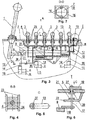
- Fig. 1 represents a general view of the device assembly with the gearbox lever in the rear position
- Fig. 2 represents a plan view of Fig. 1
- Fig. 3 represents a longitudinal section of the device
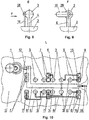
- Fig. 4 is a view taken along B-B line of Fig. 3
- Fig. 5 is a view taken along C of Fig. 6
- Fig. 6 is a detailed view I of Fig. 3
- Fig. 7 is a view taken along line D-D of Fig. 3
- Fig.8 is a view taken along E of Fig. 3
- Fig. 9 - is a view taken along F of Fig. 8
- Fig. 10 is a view taken along L of Fig.
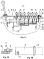
- Fig.11 represents a general view of the device assembly with the gearbox lever in the front position
- Fig. 12 - is a view G of Fig. 11
- Fig. 13 represents a plan view of Fig. 12
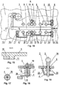
- Fig. 14 - is a view taken along A of Fig. 3
- Fig.15 is a view taken along the line H - H of Fig. 14
- Fig. 16 is a variant of the fixer of Fig. 6
- Fig. 17 - is a view taken along the line J-J of Fig. 16
- Fig. 18 - represents an enlarged cross sectional view of the rod.
- the keyless anti-theft device comprises a security part, a gearbox 2 lever 1 locking means and a drive mechanism of the locking means.
- the security part is made in the form of a set of code and false keys 3 with rods 4 mounted into the gearbox by means of seals 5 and connected by means of three-dimensional levers 6 with weights 7 and 8 of the drive mechanism of the locking means which is in the form of a rocker arm 9 vertically pivotable about the axis 10.
- the locking end of the rocker arm 9 is provided with a limiter 11 for limiting the travel of a gearbox lever adapted for interacting with a stop piece 12 rigidly connected to the gearbox 2 lever 1.
- the device is provided with a limiter 13 for limiting the rocker arm 9 locking end descending travel.
- Three-dimensional levers 6 are connected to the weights 7 and 8 through flexible ties 14. All the weights are freely arranged in open-top baskets 15 rigidly connected to said rocker arm 9 and equipped with tongues 16 preventing the weights 7 and 8 from falling out the baskets 15.
- the baskets 15 are arranged longitudinally on either side of the rocker arm 9 mounting axis 10, thus, forming at least one horizontal row.
- the rocker arm 9 locking part has baskets 15 rigidly attached thereto, wherein the tightening weights 7 of the baskets are connected to the false keys, and the other, i.e.
- the ballast, part of the rocker arm 9 has baskets 15 rigidly attached thereto being able to receive at least three counterweights 8 connected to the code keys.
- the ratio of the total weights of each rocker arm 9 locking and ballast parts is obtained in order to allow the rocker arm 9 pivoting towards the ballast part when loaded with a set of counterweights 8; and the rocker arm 9 pivoting towards the locking part when loaded with at least one tightening weight 7 when the ballast part baskets 15 are completely loaded or the rocker arm 9 both locking and ballast parts not loaded at all.
- each of said code key rods 4 and the travel of associated counterweight 8 is equal to the value B, thus, allowing the latters stopping at the bottom of the rocker arm 9 ballast part basket 15 in the locked position of the gearbox 2 lever 1.
- the value B is inherent to all the false key tightening weights 7.
- the distance between the bottom of the baskets 15 of the rocker arm 9 locking part, more remote from the arm rocker axis 10, and the weights being in contact is equal to the sum of the values B + K 2 , wherein the value K 2 is less than the travel K 1 of the rocker arm locking means till the gearbox 2 lever 1 coming out of the stop piece 12 interaction, and the value B is not less than the value K 1 .
- Each of the rods 3 is equipped with a rotation limiter and axial movement limiters limiting the axial up and down movement and with an upper position stop, performed as a hinge pedestal 16, wherein the security part is equipped with a means for balancing the total weight of each of the moveable elements.
- a vane-type fixer is arranged to fix the rocker arm 9 open position, and said weights, i.e. counterweights 8 and tightening weights 7, are made of magnetically resistant materials.
- the locking means is performed in the form of a downward projection 11 adapted to contact the gearbox lever stop piece 12 in the operation position of the device and to fix the gearbox 2 lever 1 in its front position, or it can be performed as a cross slot adapted to freely engage with a projection provided at the end of the gearbox lever stop piece in its rear position.
- the open position fixer of the gearbox lever locking means is performed as a pivot lever 17 having a vane 18 arranged on its free end and engaged in the operation position with the rocker arm 9 and having a handle 19 on the other end, and in its middle part said lever 17 has limiters 20 and 21 for limiting its vertical travel.
- the lever 17 and the rods 4 are passed through a support plate 22.
- Each rod 4 hinge pedestal 16 has a height providing its fixing in the upper position.
- Each rod 4 rotation limiter is performed as two plates 23 attached to the gearbox, surrounding from either side a rectangular cross-section insert 24 integral with the rod 4.
- the means for balancing the total weight of each of the security part moveable elements can be performed as additional weights 25 attached to the rod 4, the weight of which provides equal total weights of the security part movable elements, and simultaneously the additional weights act as said rod 4 axial movement limiters.
- the rigid ties between the baskets 15 and the rocker arm 9 can be performed, for example, as pins 26, with flexible ties 14 arranged along them.
- the means for balancing the total weight of each of the security part moveable elements also can be performed by changing each three-dimensional lever material consumption and by using for each three-dimensional lever 6 different specific weight materials, as well as the total weight balancing for each of the security part moveable elements can be performed by material removal, such as through or blind openings in each three-dimensional lever 6, whose weight exceeds reference one.
- the limiter for limiting the rocker arm locking end descending travel can be performed as a pedestal 13 fixed to the gearbox and adapted for interacting with the rocker arm 9 ballast end.
- the vane 18 pivot lever 17 has a handle 19 fixed, for example, with a slotted stop washer 27, and a pedestal 16 is arranged on the axis 28.
- the rocker arm 9 may be placed at the gearbox side wall; in this case it is L-shaped ( Fig. 10 , Fig. 14 ) with corresponding changes in its shape and the gearbox lever stop piece 12 attachment point.
- the device operates as follows.
- the code keys are pressed down and the counterweights 8 are released together with the baskets 15 are lowered by the length B. Due to this, the ballast part descends and the rocker arm 9 disengages the stop piece 12 enabling the car to start off. Thus, the rocker arm is locked with the vane 18 and then all the key 3 rods are moved downwards.
- the tightening weights 7 of the false keys equally spaced from the code keys also descend by the value B and a malefactor can't distinguish them from the code keys by their travel length.
- the use of the device allows for increasing the security and expanding the operational capacities due to the reduced weight.
Landscapes
- Engineering & Computer Science (AREA)
- General Engineering & Computer Science (AREA)
- Mechanical Engineering (AREA)
- General Details Of Gearings (AREA)
- Lock And Its Accessories (AREA)
- Arrangement Or Mounting Of Control Devices For Change-Speed Gearing (AREA)
- Gear-Shifting Mechanisms (AREA)
Claims (13)
- Schlüssellose Diebstahlsicherung, umfassend einen Sicherheitsteil, ein Getriebe (2), einen Getriebehebel (1), ein Verriegelungsmittel und einen Antriebsmechanismus für das Verriegelungsmittel, wobei
der Sicherheitsteil als eine Gruppe von Kodetasten und falschen Tasten (3) mit Stangen (4), die im Getriebe (2) mittels Dichtungen (5) befestigt und mittels dreidimensionaler Hebel (6) mit Gewichtselementen (7), (8) des Antriebsmechanismus des Verriegelungsmittels verbunden sind, ausgeführt ist;
das Verriegelungsmittels als ein um eine Achse (10) vertikal schwenkbarer Kipphebel (9) ausgeführt ist, wobei das Verriegelungsende des Kipphebels (9) einen Begrenzer (11) zur Begrenzung der Bewegung des Getriebehebels erhält, der zum Zusammenwirken mit einem mit dem Getriebehebel (1) fest verbundenen Anschlag (12) konfiguriert ist;
die Diebstahlsicherung einen Begrenzer (13) zur Begrenzung der Abwärtsbewegung des Verriegelungsendes des Kipphebels (9) erhält;
dadurch gekennzeichnet, dass
die dreidimensionalen Hebel (6) durch flexible Verbindungen (14) mit den Gewichtselementen (7), (8) verbunden sind, wobei die Gewichtselemente jeweils in oben offenen Körben (15) ungehindert angeordnet sind, die mit dem Kipphebel (9) fest verbunden sind und das Fallen der Gewichtselemente (7), (8) aus den Körben (15) verhindernde Lappen (16) erhalten;
die Körbe (15) längs auf beiden Seiten der Befestigungsachse (10) des Kipphebels (9) in mindestens einer horizontalen Reihe angeordnet sind, wobei die Körbe (15), dessen Lastgewichtselemente (7) mit den falschen Tasten verbunden sind, am Verriegelungsteil des Kipphebels (9) starr befestigt sind; und die Körbe (15), die mindestens drei mit den Kodetasten verbundene Gegengewichtselemente (8) aufnehmen können, am anderen Teil, das heißt am Ballastteil, des Kipphebels (9) starr befestigt sind, wobei das Verhältnis zwischen dem Totalgewichte des Verriegelungs- und Balastteils des Kipphebels (9) bekommen ist, damit der Kipphebel (9) in Richtung des Ballastteils geschwenkt sein kann, wenn er durch die Gruppe der Gegengewichtselemente (8) belastet ist, und in Richtung des Verriegelungsteils geschwenkt werden kann, wenn er durch mindestens ein Lastgewichtselement (7) belastet ist und die Körbe (15) des Ballastteils vollständig beladet sind oder der Verriegelungs- und ballastteils des Kipphebels (9) gar nicht belastet sind;
wobei die Bewegung jeder der Stangen (4) der Kodetasten und die Bewegung des mit ihr verbundenen Gegengewichtselements (8) einem Wert B gleich sind, so dass die Letzten sich in der Verriegelungsposition des Getriebehebels (1) gegen den Boden des Korbes (15) des Ballastteils des Kipphebels (9) stützen können, wobei jedes der Lastgewichtselemente (7) der falschen Tasten auch den Wert B hat, und der Abstand zwischen dem Boden der Körbe (15) der falschen Tasten in den Verriegelungsteil des Kipphebels (9), die von der Achse (10) des Kipphebels mehr entfernt sind, und den Gewichtselementen, wenn sie in Kontakt stehen, der Summe von B + K2 gleich ist, wobei der Wert K2 kleiner als die Bewegung K1 des Verriegelungsmittels des Kipphebels ist, bevor der Anschlag (12) des Getriebehebels (1) außer Eingriff kommt, und der Wert B nicht kleiner als der Wert K1 ist;
wobei jede der Stangen (3) einen Drehungsbegrenzer und axiale Aufwärts- und Abwärtsbewegungen begrenzende Begrenzer, sowie einen Stopper der oberen Position, der als einen Gelenkbock (16) ausgeführt ist, umfasst, wobei der Sicherheitsteil ein Mittel zum Ausgleich des Totalgewichts aller beweglichen Elemente umfasst, wobei ein flügelartiger Fixator zur Fixierung der offenen Position des Kipphebels (9) im oberen Teil des Getriebes angeordnet ist, und die Gewichtselemente, das heißt die Gegengewichtselemente (8) und Lastgewichtselemente (7), aus magnetisch widerstandsfähig Materialien sind, wobei der Getriebehebel (1) und die Stangen (4) durch eine Stützplatte hindurchgeführt sind. - Schlüssellose Diebstahlsicherung nach Anspruch 1, dadurch gekennzeichnet, dass das Verriegelungsmittel als ein nach unten gerichteter Vorsprung ausgeführt ist, der in der Arbeitsstellung der Diebstahlsicherung zum Kontaktieren mit dem Anschlag (12) des Getriebehebels und zur Fixierung des Getriebehebels (1) in seiner vorderen Position konfiguriert ist.
- Schlüssellose Diebstahlsicherung nach Anspruch 1, dadurch gekennzeichnet, dass das Verriegelungsmittel als ein Kreuzschlitz ausgeführt ist, der zum ungehinderten Eingriff mit einem auf dem Ende des Anschlags (12) des Getriebehebels vorgesehenen Vorsprung in seiner hinteren Position konfiguriert ist.
- Schlüssellose Diebstahlsicherung nach Anspruch 1, dadurch gekennzeichnet, dass der Fixator der offenen Position des Verriegelungsmittels des Getriebehebels als ein Schwenkhebel (17) ausgeführt ist, der einen Flügel (18), der auf seinem freien Ende angeordnet und in der Arbeitsstellung mit dem Kipphebel (9) im Eingriff ist, sowie einen Griff (19) auf dem anderen Ende erhält, und am Mittelteil des Schwenkhebels (17) Begrenzer (20), (21) zur Begrenzung seine vertikale Bewegung vorgesehen sind.
- Schlüssellose Diebstahlsicherung nach Anspruch 4, dadurch gekennzeichnet, dass das Mittel zur Begrenzung der vertikalen Bewegung des Schwenkhebels (17) als zwei voneinander beabstandete Hülsen oder eine Hülse mit der Höhe, die dem Abstand zwischen dem Oberteil des Getriebes und der Stützplatte (22) gleich ist, ausgeführt ist.
- Schlüssellose Diebstahlsicherung nach Anspruch 1, dadurch gekennzeichnet, dass der Kipphebel (9) L-förmig ausgeführt und zur Seitenwand des Getriebes verschoben ist.
- Schlüssellose Diebstahlsicherung nach Anspruch 1, dadurch gekennzeichnet, dass der Gelenkbock (16) jeder Stange solche Höhe hat, die seine Fixierung in der oberen Position ermöglicht.
- Schlüssellose Diebstahlsicherung nach Anspruch 1, dadurch gekennzeichnet, dass der Drehungsbegrenzer jeder Stange als zwei Platten ausgeführt ist, die am Getriebe (2) befestigt sind und einen mit der Stange unlösbar verbundenen Einsatz mit rechteckigem Querschnitt beiderseits umgeben.
- Schlüssellose Diebstahlsicherung nach Anspruch 1, dadurch gekennzeichnet, dass das Mittel zum Ausgleich des Totalgewichts jedes der beweglichen Elemente des Sicherheitsteils als zusätzliche Gewichtselemente ausgeführt ist, die an der Stange befestigt sind und deren Gewicht die Totalgewichte der beweglichen Elemente des Sicherheitsteils gleich macht, wobei die zusätzlich Gewichtselemente gleichzeitig als die Begrenzers (11), (13) der Axialbewegung der Stange dienen.
- Schlüssellose Diebstahlsicherung nach Anspruch 1, dadurch gekennzeichnet, dass das Mittel zum Ausgleich des Totalgewichts jedes der beweglichen Elemente des Sicherheitsteils durch die Änderung des Materialverbrauchs jedes dreidimensionalen Hebels (6) ausgeführt ist.
- Schlüssellose Diebstahlsicherung nach Anspruch 1, dadurch gekennzeichnet, dass das Mittel zum Ausgleich des Totalgewichts jedes der beweglichen Elemente des Sicherheitsteils durch die Verwendung von Materialien mit verschiedenem spezifischem Gewicht für jeden dreidimensionalen Hebel (6) ausgeführt ist.
- Schlüssellose Diebstahlsicherung nach Anspruch 1, dadurch gekennzeichnet, dass das mittel zum Ausgleich des Totalgewichts jedes der beweglichen Elemente des Sicherheitsteils durch Materialentfernung mittels Durch- oder Grundbohrungen in jedem dreidimensionalen Hebel (6) ausgeführt ist, dessen Gewicht größer als das Referenzgewicht ist.
- Schlüssellose Diebstahlsicherung nach Anspruch 1, dadurch gekennzeichnet, dass die Begrenzer (13) zur Begrenzung der Abwärtsbewegung des Verriegelungsendes des Kipphebels (9) als ein Bock ausgeführt ist, der am Getriebe (2) befestigt und zum Zusammenwirken mit dem Ballastende des Kipphebels konfiguriert ist.
Applications Claiming Priority (2)
| Application Number | Priority Date | Filing Date | Title |
|---|---|---|---|
| RU2012132530 | 2012-07-30 | ||
| PCT/RU2012/000691 WO2014021732A1 (ru) | 2012-07-30 | 2012-08-22 | Бесключевое противоугонное устройство |
Publications (3)
| Publication Number | Publication Date |
|---|---|
| EP2881288A1 EP2881288A1 (de) | 2015-06-10 |
| EP2881288A4 EP2881288A4 (de) | 2016-03-30 |
| EP2881288B1 true EP2881288B1 (de) | 2017-09-06 |
Family
ID=50028300
Family Applications (1)
| Application Number | Title | Priority Date | Filing Date |
|---|---|---|---|
| EP12882497.6A Not-in-force EP2881288B1 (de) | 2012-07-30 | 2012-08-22 | Schlüssellose diebstahlsichere vorrichtung |
Country Status (6)
| Country | Link |
|---|---|
| US (1) | US20150210248A1 (de) |
| EP (1) | EP2881288B1 (de) |
| JP (1) | JP2015529591A (de) |
| KR (1) | KR101587372B1 (de) |
| CN (1) | CN104245441B (de) |
| WO (1) | WO2014021732A1 (de) |
Families Citing this family (2)
| Publication number | Priority date | Publication date | Assignee | Title |
|---|---|---|---|---|
| US10044710B2 (en) | 2016-02-22 | 2018-08-07 | Bpip Limited Liability Company | Device and method for validating a user using an intelligent voice print |
| CN109849848B (zh) * | 2017-11-30 | 2021-09-17 | 长城汽车股份有限公司 | 车辆防盗方法及系统 |
Family Cites Families (19)
| Publication number | Priority date | Publication date | Assignee | Title |
|---|---|---|---|---|
| US1969350A (en) * | 1933-06-01 | 1934-08-07 | Frank Bulanda | Automobile lock for gear shift levers |
| US2162995A (en) * | 1939-03-07 | 1939-06-20 | George H Bruington | Button operated combination lock |
| US2997872A (en) * | 1958-10-02 | 1961-08-29 | Brooks Carroll | Lock |
| US4350031A (en) * | 1976-12-14 | 1982-09-21 | Junichi Shimono | Pushbutton operated door locks |
| US4709564A (en) * | 1985-11-15 | 1987-12-01 | Osaka Kanagu Co., Ltd. | Digital lock |
| SE8702083L (sv) * | 1987-05-20 | 1988-11-21 | Agneta Nordberg | Laasbart stoeldskydd foer fordon |
| US4866958A (en) * | 1988-08-26 | 1989-09-19 | Lock-R-Lock | Push-button lock mechanisms |
| JPH04119251A (ja) * | 1990-09-07 | 1992-04-20 | Nissan Shatai Co Ltd | シフトレバーのロック装置 |
| DE4120382C2 (de) * | 1991-06-20 | 1993-10-28 | Porsche Ag | Verriegelungsvorrichtung zwischen einem Wählhebel eines Getriebes und einem Zündschloß eines Kraftfahrzeuges |
| FR2686851A1 (fr) * | 1992-02-03 | 1993-08-06 | Valeo Securite Habitacle | Antivol pour vehicule automobile. |
| US5720193A (en) * | 1995-04-11 | 1998-02-24 | Dick; Daniel J. | Push button firearm lock |
| US5950464A (en) * | 1998-02-12 | 1999-09-14 | Tonne; Harry E. | Gear shift lever quick release locking system |
| CN2353612Y (zh) * | 1999-01-18 | 1999-12-15 | 吴正敏 | 机械式汽车防盗装置 |
| JP4481438B2 (ja) * | 2000-05-31 | 2010-06-16 | 株式会社東海理化電機製作所 | シフト装置 |
| KR20030035107A (ko) * | 2001-10-30 | 2003-05-09 | 현대자동차주식회사 | 수동변속기 차량의 변속레버 고정을 이용한차량도난방지장치 |
| JP2009009631A (ja) * | 2007-06-27 | 2009-01-15 | Sumitomo Bakelite Co Ltd | フレキシブル配線ユニットおよび電子機器 |
| JP2009096311A (ja) | 2007-10-16 | 2009-05-07 | Toyota Motor Corp | 車両の盗難防止構造 |
| RU108370U1 (ru) | 2011-05-16 | 2011-09-20 | Александр Константинович Сидоров | Механическое противоугонное устройство автомобиля |
| KR101305674B1 (ko) * | 2011-06-09 | 2013-09-09 | 현대자동차주식회사 | 시동제어타입 오토레버장치 |
-
2012
- 2012-08-22 KR KR1020147023653A patent/KR101587372B1/ko not_active Expired - Fee Related
- 2012-08-22 JP JP2015525398A patent/JP2015529591A/ja active Pending
- 2012-08-22 WO PCT/RU2012/000691 patent/WO2014021732A1/ru not_active Ceased
- 2012-08-22 CN CN201280072415.9A patent/CN104245441B/zh not_active Expired - Fee Related
- 2012-08-22 EP EP12882497.6A patent/EP2881288B1/de not_active Not-in-force
- 2012-08-22 US US14/375,040 patent/US20150210248A1/en not_active Abandoned
Non-Patent Citations (1)
| Title |
|---|
| None * |
Also Published As
| Publication number | Publication date |
|---|---|
| CN104245441A (zh) | 2014-12-24 |
| JP2015529591A (ja) | 2015-10-08 |
| US20150210248A1 (en) | 2015-07-30 |
| EP2881288A1 (de) | 2015-06-10 |
| CN104245441B (zh) | 2016-06-22 |
| EP2881288A4 (de) | 2016-03-30 |
| KR20140131931A (ko) | 2014-11-14 |
| WO2014021732A1 (ru) | 2014-02-06 |
| KR101587372B1 (ko) | 2016-01-20 |
Similar Documents
| Publication | Publication Date | Title |
|---|---|---|
| EP2881288B1 (de) | Schlüssellose diebstahlsichere vorrichtung | |
| EP2543801A3 (de) | Sichere Türgriffeinheit | |
| US20120261212A1 (en) | Anti-panic descender with possibility of ascent | |
| WO2008071246A1 (en) | Flexible trap door for access platforms | |
| EP2592203A3 (de) | Schloss | |
| KR101470248B1 (ko) | 차량 측면 충돌 시 도어 열림 방지장치 | |
| US1129536A (en) | Safety device for elevators. | |
| JP2012030955A (ja) | エレベータ乗場の戸手動開閉装置。 | |
| JP2014151723A (ja) | 可動ホーム柵扉 | |
| US8998334B2 (en) | Head support that can be moved in the X direction | |
| EP2316774B1 (de) | Aufzugskabine | |
| CN105858421B (zh) | 电梯的门装置 | |
| JP5909828B2 (ja) | 電子機器用ラック | |
| CN217106557U (zh) | 锁具及宠物航空箱 | |
| US999318A (en) | Window-operating mechanism. | |
| CN204689331U (zh) | 机械式轿厢门锁定装置 | |
| JP6963756B2 (ja) | エレベータ用乗場ドア及びエレベータ | |
| JP2017206364A (ja) | エレベータ救出装置 | |
| JP6069083B2 (ja) | 建築用シャッター装置におけるシャッターケース | |
| JP6930857B2 (ja) | 移動棚のロック装置 | |
| JP5053171B2 (ja) | エスカレータ用作業箱 | |
| JP5607794B1 (ja) | エレベータの三方枠 | |
| CN104723872A (zh) | 换挡手提机构及应用其的换挡器和汽车 | |
| US595943A (en) | Safety device foe elevators | |
| DD154289A1 (de) | Fahrkorb fuer personen und/oder lasten |
Legal Events
| Date | Code | Title | Description |
|---|---|---|---|
| PUAI | Public reference made under article 153(3) epc to a published international application that has entered the european phase |
Free format text: ORIGINAL CODE: 0009012 |
|
| 17P | Request for examination filed |
Effective date: 20140724 |
|
| AK | Designated contracting states |
Kind code of ref document: A1 Designated state(s): AL AT BE BG CH CY CZ DE DK EE ES FI FR GB GR HR HU IE IS IT LI LT LU LV MC MK MT NL NO PL PT RO RS SE SI SK SM TR |
|
| AX | Request for extension of the european patent |
Extension state: BA ME |
|
| DAX | Request for extension of the european patent (deleted) | ||
| RA4 | Supplementary search report drawn up and despatched (corrected) |
Effective date: 20160226 |
|
| RIC1 | Information provided on ipc code assigned before grant |
Ipc: F16H 61/22 20060101ALI20160222BHEP Ipc: B60R 25/06 20060101AFI20160222BHEP Ipc: F16H 59/02 20060101ALI20160222BHEP |
|
| GRAP | Despatch of communication of intention to grant a patent |
Free format text: ORIGINAL CODE: EPIDOSNIGR1 |
|
| INTG | Intention to grant announced |
Effective date: 20170609 |
|
| GRAS | Grant fee paid |
Free format text: ORIGINAL CODE: EPIDOSNIGR3 |
|
| GRAA | (expected) grant |
Free format text: ORIGINAL CODE: 0009210 |
|
| AK | Designated contracting states |
Kind code of ref document: B1 Designated state(s): AL AT BE BG CH CY CZ DE DK EE ES FI FR GB GR HR HU IE IS IT LI LT LU LV MC MK MT NL NO PL PT RO RS SE SI SK SM TR |
|
| REG | Reference to a national code |
Ref country code: GB Ref legal event code: FG4D |
|
| REG | Reference to a national code |
Ref country code: CH Ref legal event code: EP Ref country code: AT Ref legal event code: REF Ref document number: 925503 Country of ref document: AT Kind code of ref document: T Effective date: 20170915 |
|
| REG | Reference to a national code |
Ref country code: IE Ref legal event code: FG4D |
|
| REG | Reference to a national code |
Ref country code: DE Ref legal event code: R096 Ref document number: 602012037167 Country of ref document: DE |
|
| REG | Reference to a national code |
Ref country code: NL Ref legal event code: MP Effective date: 20170906 |
|
| REG | Reference to a national code |
Ref country code: LT Ref legal event code: MG4D |
|
| PG25 | Lapsed in a contracting state [announced via postgrant information from national office to epo] |
Ref country code: SE Free format text: LAPSE BECAUSE OF FAILURE TO SUBMIT A TRANSLATION OF THE DESCRIPTION OR TO PAY THE FEE WITHIN THE PRESCRIBED TIME-LIMIT Effective date: 20170906 Ref country code: HR Free format text: LAPSE BECAUSE OF FAILURE TO SUBMIT A TRANSLATION OF THE DESCRIPTION OR TO PAY THE FEE WITHIN THE PRESCRIBED TIME-LIMIT Effective date: 20170906 Ref country code: FI Free format text: LAPSE BECAUSE OF FAILURE TO SUBMIT A TRANSLATION OF THE DESCRIPTION OR TO PAY THE FEE WITHIN THE PRESCRIBED TIME-LIMIT Effective date: 20170906 Ref country code: LT Free format text: LAPSE BECAUSE OF FAILURE TO SUBMIT A TRANSLATION OF THE DESCRIPTION OR TO PAY THE FEE WITHIN THE PRESCRIBED TIME-LIMIT Effective date: 20170906 Ref country code: NO Free format text: LAPSE BECAUSE OF FAILURE TO SUBMIT A TRANSLATION OF THE DESCRIPTION OR TO PAY THE FEE WITHIN THE PRESCRIBED TIME-LIMIT Effective date: 20171206 |
|
| REG | Reference to a national code |
Ref country code: AT Ref legal event code: MK05 Ref document number: 925503 Country of ref document: AT Kind code of ref document: T Effective date: 20170906 |
|
| PG25 | Lapsed in a contracting state [announced via postgrant information from national office to epo] |
Ref country code: ES Free format text: LAPSE BECAUSE OF FAILURE TO SUBMIT A TRANSLATION OF THE DESCRIPTION OR TO PAY THE FEE WITHIN THE PRESCRIBED TIME-LIMIT Effective date: 20170906 Ref country code: BG Free format text: LAPSE BECAUSE OF FAILURE TO SUBMIT A TRANSLATION OF THE DESCRIPTION OR TO PAY THE FEE WITHIN THE PRESCRIBED TIME-LIMIT Effective date: 20171206 Ref country code: RS Free format text: LAPSE BECAUSE OF FAILURE TO SUBMIT A TRANSLATION OF THE DESCRIPTION OR TO PAY THE FEE WITHIN THE PRESCRIBED TIME-LIMIT Effective date: 20170906 Ref country code: LV Free format text: LAPSE BECAUSE OF FAILURE TO SUBMIT A TRANSLATION OF THE DESCRIPTION OR TO PAY THE FEE WITHIN THE PRESCRIBED TIME-LIMIT Effective date: 20170906 Ref country code: GR Free format text: LAPSE BECAUSE OF FAILURE TO SUBMIT A TRANSLATION OF THE DESCRIPTION OR TO PAY THE FEE WITHIN THE PRESCRIBED TIME-LIMIT Effective date: 20171207 |
|
| PG25 | Lapsed in a contracting state [announced via postgrant information from national office to epo] |
Ref country code: NL Free format text: LAPSE BECAUSE OF FAILURE TO SUBMIT A TRANSLATION OF THE DESCRIPTION OR TO PAY THE FEE WITHIN THE PRESCRIBED TIME-LIMIT Effective date: 20170906 |
|
| PG25 | Lapsed in a contracting state [announced via postgrant information from national office to epo] |
Ref country code: RO Free format text: LAPSE BECAUSE OF FAILURE TO SUBMIT A TRANSLATION OF THE DESCRIPTION OR TO PAY THE FEE WITHIN THE PRESCRIBED TIME-LIMIT Effective date: 20170906 Ref country code: CZ Free format text: LAPSE BECAUSE OF FAILURE TO SUBMIT A TRANSLATION OF THE DESCRIPTION OR TO PAY THE FEE WITHIN THE PRESCRIBED TIME-LIMIT Effective date: 20170906 Ref country code: PL Free format text: LAPSE BECAUSE OF FAILURE TO SUBMIT A TRANSLATION OF THE DESCRIPTION OR TO PAY THE FEE WITHIN THE PRESCRIBED TIME-LIMIT Effective date: 20170906 |
|
| PG25 | Lapsed in a contracting state [announced via postgrant information from national office to epo] |
Ref country code: IS Free format text: LAPSE BECAUSE OF FAILURE TO SUBMIT A TRANSLATION OF THE DESCRIPTION OR TO PAY THE FEE WITHIN THE PRESCRIBED TIME-LIMIT Effective date: 20180106 Ref country code: EE Free format text: LAPSE BECAUSE OF FAILURE TO SUBMIT A TRANSLATION OF THE DESCRIPTION OR TO PAY THE FEE WITHIN THE PRESCRIBED TIME-LIMIT Effective date: 20170906 Ref country code: SK Free format text: LAPSE BECAUSE OF FAILURE TO SUBMIT A TRANSLATION OF THE DESCRIPTION OR TO PAY THE FEE WITHIN THE PRESCRIBED TIME-LIMIT Effective date: 20170906 Ref country code: AT Free format text: LAPSE BECAUSE OF FAILURE TO SUBMIT A TRANSLATION OF THE DESCRIPTION OR TO PAY THE FEE WITHIN THE PRESCRIBED TIME-LIMIT Effective date: 20170906 Ref country code: IT Free format text: LAPSE BECAUSE OF FAILURE TO SUBMIT A TRANSLATION OF THE DESCRIPTION OR TO PAY THE FEE WITHIN THE PRESCRIBED TIME-LIMIT Effective date: 20170906 Ref country code: SM Free format text: LAPSE BECAUSE OF FAILURE TO SUBMIT A TRANSLATION OF THE DESCRIPTION OR TO PAY THE FEE WITHIN THE PRESCRIBED TIME-LIMIT Effective date: 20170906 |
|
| REG | Reference to a national code |
Ref country code: DE Ref legal event code: R097 Ref document number: 602012037167 Country of ref document: DE |
|
| PLBE | No opposition filed within time limit |
Free format text: ORIGINAL CODE: 0009261 |
|
| STAA | Information on the status of an ep patent application or granted ep patent |
Free format text: STATUS: NO OPPOSITION FILED WITHIN TIME LIMIT |
|
| PG25 | Lapsed in a contracting state [announced via postgrant information from national office to epo] |
Ref country code: DK Free format text: LAPSE BECAUSE OF FAILURE TO SUBMIT A TRANSLATION OF THE DESCRIPTION OR TO PAY THE FEE WITHIN THE PRESCRIBED TIME-LIMIT Effective date: 20170906 |
|
| 26N | No opposition filed |
Effective date: 20180607 |
|
| PG25 | Lapsed in a contracting state [announced via postgrant information from national office to epo] |
Ref country code: SI Free format text: LAPSE BECAUSE OF FAILURE TO SUBMIT A TRANSLATION OF THE DESCRIPTION OR TO PAY THE FEE WITHIN THE PRESCRIBED TIME-LIMIT Effective date: 20170906 |
|
| REG | Reference to a national code |
Ref country code: DE Ref legal event code: R119 Ref document number: 602012037167 Country of ref document: DE |
|
| PG25 | Lapsed in a contracting state [announced via postgrant information from national office to epo] |
Ref country code: MC Free format text: LAPSE BECAUSE OF FAILURE TO SUBMIT A TRANSLATION OF THE DESCRIPTION OR TO PAY THE FEE WITHIN THE PRESCRIBED TIME-LIMIT Effective date: 20170906 |
|
| REG | Reference to a national code |
Ref country code: CH Ref legal event code: PL |
|
| GBPC | Gb: european patent ceased through non-payment of renewal fee |
Effective date: 20180822 |
|
| PG25 | Lapsed in a contracting state [announced via postgrant information from national office to epo] |
Ref country code: LU Free format text: LAPSE BECAUSE OF NON-PAYMENT OF DUE FEES Effective date: 20180822 Ref country code: CH Free format text: LAPSE BECAUSE OF NON-PAYMENT OF DUE FEES Effective date: 20180831 Ref country code: LI Free format text: LAPSE BECAUSE OF NON-PAYMENT OF DUE FEES Effective date: 20180831 |
|
| REG | Reference to a national code |
Ref country code: BE Ref legal event code: MM Effective date: 20180831 |
|
| PG25 | Lapsed in a contracting state [announced via postgrant information from national office to epo] |
Ref country code: DE Free format text: LAPSE BECAUSE OF NON-PAYMENT OF DUE FEES Effective date: 20190301 |
|
| PG25 | Lapsed in a contracting state [announced via postgrant information from national office to epo] |
Ref country code: BE Free format text: LAPSE BECAUSE OF NON-PAYMENT OF DUE FEES Effective date: 20180831 Ref country code: FR Free format text: LAPSE BECAUSE OF NON-PAYMENT OF DUE FEES Effective date: 20180831 |
|
| PG25 | Lapsed in a contracting state [announced via postgrant information from national office to epo] |
Ref country code: GB Free format text: LAPSE BECAUSE OF NON-PAYMENT OF DUE FEES Effective date: 20180822 |
|
| PG25 | Lapsed in a contracting state [announced via postgrant information from national office to epo] |
Ref country code: MT Free format text: LAPSE BECAUSE OF NON-PAYMENT OF DUE FEES Effective date: 20180822 |
|
| PG25 | Lapsed in a contracting state [announced via postgrant information from national office to epo] |
Ref country code: TR Free format text: LAPSE BECAUSE OF FAILURE TO SUBMIT A TRANSLATION OF THE DESCRIPTION OR TO PAY THE FEE WITHIN THE PRESCRIBED TIME-LIMIT Effective date: 20170906 |
|
| PG25 | Lapsed in a contracting state [announced via postgrant information from national office to epo] |
Ref country code: HU Free format text: LAPSE BECAUSE OF FAILURE TO SUBMIT A TRANSLATION OF THE DESCRIPTION OR TO PAY THE FEE WITHIN THE PRESCRIBED TIME-LIMIT; INVALID AB INITIO Effective date: 20120822 Ref country code: PT Free format text: LAPSE BECAUSE OF FAILURE TO SUBMIT A TRANSLATION OF THE DESCRIPTION OR TO PAY THE FEE WITHIN THE PRESCRIBED TIME-LIMIT Effective date: 20170906 |
|
| PG25 | Lapsed in a contracting state [announced via postgrant information from national office to epo] |
Ref country code: MK Free format text: LAPSE BECAUSE OF NON-PAYMENT OF DUE FEES Effective date: 20170906 Ref country code: IE Free format text: LAPSE BECAUSE OF NON-PAYMENT OF DUE FEES Effective date: 20180822 Ref country code: CY Free format text: LAPSE BECAUSE OF FAILURE TO SUBMIT A TRANSLATION OF THE DESCRIPTION OR TO PAY THE FEE WITHIN THE PRESCRIBED TIME-LIMIT Effective date: 20170906 |
|
| PG25 | Lapsed in a contracting state [announced via postgrant information from national office to epo] |
Ref country code: AL Free format text: LAPSE BECAUSE OF FAILURE TO SUBMIT A TRANSLATION OF THE DESCRIPTION OR TO PAY THE FEE WITHIN THE PRESCRIBED TIME-LIMIT Effective date: 20170906 |