EP2881175A1 - Kassettenstapel aus einzelnen Kassetten, vorzugsweise zur Aufnahme von Präparaten für Laboranalysen - Google Patents
Kassettenstapel aus einzelnen Kassetten, vorzugsweise zur Aufnahme von Präparaten für Laboranalysen Download PDFInfo
- Publication number
- EP2881175A1 EP2881175A1 EP14195559.1A EP14195559A EP2881175A1 EP 2881175 A1 EP2881175 A1 EP 2881175A1 EP 14195559 A EP14195559 A EP 14195559A EP 2881175 A1 EP2881175 A1 EP 2881175A1
- Authority
- EP
- European Patent Office
- Prior art keywords
- strand
- cassette
- cassettes
- wall
- stack according
- Prior art date
- Legal status (The legal status is an assumption and is not a legal conclusion. Google has not performed a legal analysis and makes no representation as to the accuracy of the status listed.)
- Granted
Links
- 238000002360 preparation method Methods 0.000 title claims abstract description 5
- 238000004458 analytical method Methods 0.000 title claims description 3
- 238000002372 labelling Methods 0.000 claims description 5
- 239000000463 material Substances 0.000 claims description 2
- 239000000853 adhesive Substances 0.000 description 6
- 230000001070 adhesive effect Effects 0.000 description 6
- 239000002390 adhesive tape Substances 0.000 description 5
- 238000003780 insertion Methods 0.000 description 4
- 230000037431 insertion Effects 0.000 description 4
- 238000000034 method Methods 0.000 description 3
- 238000000926 separation method Methods 0.000 description 3
- 230000015572 biosynthetic process Effects 0.000 description 1
- 238000005516 engineering process Methods 0.000 description 1
- 238000007731 hot pressing Methods 0.000 description 1
- 239000007788 liquid Substances 0.000 description 1
- 229920001296 polysiloxane Polymers 0.000 description 1
Images

Classifications
-
- B—PERFORMING OPERATIONS; TRANSPORTING
- B01—PHYSICAL OR CHEMICAL PROCESSES OR APPARATUS IN GENERAL
- B01L—CHEMICAL OR PHYSICAL LABORATORY APPARATUS FOR GENERAL USE
- B01L9/00—Supporting devices; Holding devices
- B01L9/52—Supports specially adapted for flat sample carriers, e.g. for plates, slides, chips
-
- B—PERFORMING OPERATIONS; TRANSPORTING
- B01—PHYSICAL OR CHEMICAL PROCESSES OR APPARATUS IN GENERAL
- B01L—CHEMICAL OR PHYSICAL LABORATORY APPARATUS FOR GENERAL USE
- B01L2200/00—Solutions for specific problems relating to chemical or physical laboratory apparatus
- B01L2200/02—Adapting objects or devices to another
- B01L2200/025—Align devices or objects to ensure defined positions relative to each other
-
- B—PERFORMING OPERATIONS; TRANSPORTING
- B01—PHYSICAL OR CHEMICAL PROCESSES OR APPARATUS IN GENERAL
- B01L—CHEMICAL OR PHYSICAL LABORATORY APPARATUS FOR GENERAL USE
- B01L2300/00—Additional constructional details
- B01L2300/08—Geometry, shape and general structure
- B01L2300/0809—Geometry, shape and general structure rectangular shaped
- B01L2300/0812—Bands; Tapes
-
- B—PERFORMING OPERATIONS; TRANSPORTING
- B01—PHYSICAL OR CHEMICAL PROCESSES OR APPARATUS IN GENERAL
- B01L—CHEMICAL OR PHYSICAL LABORATORY APPARATUS FOR GENERAL USE
- B01L2300/00—Additional constructional details
- B01L2300/08—Geometry, shape and general structure
- B01L2300/0809—Geometry, shape and general structure rectangular shaped
- B01L2300/0829—Multi-well plates; Microtitration plates
Definitions
- the invention relates to a cassette stack of individual cassettes, preferably for receiving preparations for laboratory analysis, according to the preamble of patent claim 1.
- the cassettes of such a stack serve, for example, in medical laboratories as receptacles for histological samples.
- the cassettes are labeled manually or mechanically for your distinction.
- cassettes are connected to a cassette stack with each other, which is then inserted into a slot. The easiest way to connect the stacked cassettes by means of a guided around them outside cord.
- connection technology would be possible to connect the cassette by means of a drawn along the cassette stack adhesive seam, such as a glued seam of silicone, hot or liquid adhesive. But even in this case would be the slicing, loosening or separating the adhesive seam through in this Area existing walls or wall areas of the printer shaft difficult. In addition, residues may adhere to the cassettes after separation of the adhesive seam, which may make it difficult for the cassettes to slip in the printer tray or cassette magazine.
- the invention is therefore based on the object to propose measures in such a stack of cartridges, which further simplify the handling of the cartridge stack, especially in the context of the printing process and its preparation.
- the resistance moment is a transverse element at the lower end of the strand.
- the cross member prevents the strand from being pulled out of the openings or recesses of the cassette stack already in an attempt to support or lift the cassette stack.
- the resistance element is an end section of the strand which is deformed with respect to the remaining strand path. As a resistance element therefore no additional component is needed.
- a particularly simple way to use the strand itself as a resistance element it is when the resistance element over the other strand course angled end portion of the strand is. So that all individual cassettes of the cassette stack can be raised via a single strand, the angled end section is preferably supported against the underside of the lowermost cassette.
- the strand is a flat strip, preferably made of plastic, and that the opening or recess for receiving the flat strip is of oblong cross-section.
- a ribbon can be well threaded into a corresponding slot-shaped opening or recess in the cassette.
- a side wall of the cassette has a printable labeling field, and that the opening or recess is arranged in the region of this side wall, and further that a side wall is a double wall and composed of an outer wall having the printable label field, and an inner wall, and that the opening or recess is formed by the gap between the two walls.
- the opening or recess is further a latching element for closing the cassette by means of a lid.
- the opening or recess thus has a double function. On the one hand, it provides space for the passage of the strand, on the other hand, it is part of a closing device for a cover of the cassette. It can therefore be used simultaneously as a passage for the strand for closing the cassette anyway existing opening or recess, so that no additional design measures must be made to the cassette.
- the inner wall is arranged at right angles, and the outer wall is arranged at an angle to the bottom of the cassette with the formation of a V-angle. This arrangement is of great advantage when inserting the strand.
- the loop is formed from the material of the strand. This embodiment makes it possible to produce a strand with a loop and cross member from a conventional ribbon without additional elements.
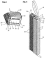
- FIG. 1 shows in a sectional view a side view of a cassette stack while it is introduced from above into a printer shaft 4 of a printer suitable for printing on the cartridges.
- the section runs centrally through the threaded onto a common strand 8 cassettes.
- the representation Fig. 1 is also interrupted twice. In the bottom part of the already introduced into the printer tray 4 cassettes 2 are visible.
- the base 10 of the printing tray 4 and its extension in the longitudinal direction of the cassette 2 is designed such that the inserted cassettes 2 rest in a certain inclination of about 20 °.
- Fig. 1 shows the cassette stack just introduced from above with the cassettes 2 threaded on the strand 8, a loop 12 at the upper end of the strand 8 and a resistance element 14 at the lower end.
- This is designed as an angled end portion of the strand 8, which is located below the bottom 16 of the bottom cassette 2 of the cassette stack, and is supported from below against this bottom 16.
- the cassettes 2 Due to the fact that the cassettes 2 are connected to one another only loosely threaded together by the strand 8 designed as a flat strip and that they are not fastened individually to the strand, the cassettes 2 can enter into the inclined position advantageous for printing when they are introduced into the shaft 4. While all the cassettes 2 of the upper part of the illustration are stacked substantially horizontally yet, changes this in the middle part of FIG. 1 Increasing from top to bottom, so that the bottom cassettes 2 take the desired inclination.
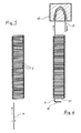
- FIG. 2 is just the cartridge stack off FIG. 1 represented, wherein in an upper partial section can be seen how the strand 8 is passed through all the cassettes 2 within the cassette stack, but without the individual cassettes are fixed in the strand longitudinal direction of the strand 8.
- FIG. 2 unrecognizable openings 18 of the cassettes 2 will be described in more detail below.
- FIG. 2 A lower part section in Fig. 2 as well as the Fig. 3 shows how the strand 8 is bent at right angles below the lowest cassette 2 at an angled portion 28, so that the angled longitudinal portion forms the resistance element 14 arranged transversely to the rest of the strand.
- the angled end portion of the strand 8 is supported against the bottom 16 and against the bottom 20 of the lowermost cassette 2, and thus supports all the cassettes 2 of the cassette stack.
- Each cassette 2 consists of a perforated bottom 16 and side walls 24.
- the perforations may be holes 22 or other apertures of any shape.
- each side wall shown on the left is a double wall 23 and consists of an inner wall 25 and an outer wall 26, which also serves as a printable labeling field 26. While the inner wall 25 is disposed at right angles to the floor 16 and connected directly thereto, the outer wall 26 extends obliquely at an angle to the upper edge of the inner wall 25. Where the inner wall 25 and the outer wall 26 meet V-shaped, a slot-shaped opening 18 for passing the flat strip 8 is arranged on the middle of the width of the cassette. The length and width of the opening 18 corresponds to the corresponding cross section of the flat belt eighth
- the angled portion 28 of the plastic flat strip 8 has such rigidity that it can absorb the weight of the threaded on the flat strip 8 cassettes 2 without major deformation.
- a certain additional pressure on the bend the bend 28 so much that after overcoming this initial resistance of the strand 8 can be pulled upwards out of the cassette 2.
- the additional pressure is generated by pulling on the loop 12 of the ribbon 8 upwards, with simultaneous downward pressure on the topmost cassette 2 of the cassette stack.
- the geometries i. H. in particular, the width of the opening 18 and the length of the angled end portion 30 of the flat strip 8, are coordinated.
- FIG. 4 shows a second embodiment of a cassette stack in a perspective view, in which each cassette 2 additionally has a lid 34.
- the cover 34 can be connected via a hinge 32 to the side wall 24 of the cassette 2 opposite the double wall 23, or the connection between the cassette base body and the cover takes place via a film hinge or a predetermined breaking point.
- the lid 34 engages on its side facing away from the hinge 32 according to the snap-lock principle by means of a hook-shaped latching element 36 in the opening 18 a.
- the opening 18 also acts as a latching element 38.
- FIGS. 5 and 6 show the process of inserting the ribbon 8 into the stack of cassettes and reshaping the top strand to form a loop 12.
- the ribbon 8 is inserted with its front end first from the bottom of the cassette ago in the cassette stack.
- the cassette stack is in this case fixed in a position in which the openings 18 of the individual cassettes are aligned with each other.
- the two forming from the bottom of the cassette forth V-shaped successive walls 25 and 26 to the slot-shaped opening 18 towards constricting funnel which greatly simplifies the insertion and then continue the Stranergfangs from cassette to cassette, so that it is sufficient to push the strand 8 forward at its rear end.
- the front portion of the flat belt after all the cassettes have been passed through, arrives in a fixedly arranged chicane 40, which passes from the flat strip 8 through approximately 180 ° becomes, whereby the loop 12 is formed.
- the loop ends are then connected, for example by hot pressing.
Landscapes
- Health & Medical Sciences (AREA)
- Clinical Laboratory Science (AREA)
- Chemical & Material Sciences (AREA)
- Chemical Kinetics & Catalysis (AREA)
- Impression-Transfer Materials And Handling Thereof (AREA)
Abstract
Description
- Die Erfindung betrifft einen Kassettenstapel aus einzelnen Kassetten, vorzugsweise zur Aufnahme von Präparaten für Laboranalysen, nach dem Oberbegriff des Patentanspruchs 1.
- Die Kassetten eines derartigen Stapels, auch Einbettkassetten genannt, dienen beispielsweise in medizinischen Laboren als Aufnahmebehälter für histologische Proben. Die Kassetten werden zu Ihrer Unterscheidung manuell oder maschinell beschriftet. Um bei der maschinellen Beschriftung nicht jede einzelne Kassette händisch separat in den Druckerschacht eines Druckers bzw. ein Kassettenmagazin einführen zu müssen, werden Kassetten zu einem Kassettenstapel miteinander verbunden, der dann in einen Schacht eingesetzt wird. Dabei ist die einfachste Möglichkeit, die aufeinanderliegenden Kassetten mittels einer außen um sie herum geführten Schnur zu verbinden.
- In der
EP 1 238 706 A2 wird vorgeschlagen, die Kassetten mittels eines längs der Kassetten verlaufenden Klebebandes miteinander zu verbinden, oder über eine dünne Schweißnaht. Hierbei ist jedoch nachteilig, dass nach dem Einführen des Kassettenstapels in den Druckerschacht bzw. in das Kassettenmagazin und vor dem Bedrucken die Kassetten nur durch Aufschneiden, Lösen bzw. durch ein Auftrennen des Klebebandes bzw. der Schweißnaht vereinzelt werden können, um sie dann als Einbettkassette nutzen zu können. Außerdem kann, je nach Gestaltung des Druckerschachts bzw. Kassettenmagazins, das Aufschneiden, Lösen bzw. Auftrennen des Klebebandes bzw. der Schweißnaht durch in diesem Bereich vorhandene Wände oder Wandbereiche des Druckerschachts behindert, zumindest aber erschwert sein. Im Fall der Verbindung der Kassetten über Klebebänder können nach dem Abtrennen des Klebebandes Klebereste außen an den Kassetten haften bleiben, was das Rutschen der Kassetten in dem Druckerschacht bzw. Kassettenmagazin erschweren kann. - Als Alternative zu der in der
EP 1 238 706 A2 beschriebenen Verbindungstechnik bestünde die Möglichkeit, die Kassetten mittels einer längs des Kassettenstapels gezogenen Klebenaht zu verbinden, etwa einer Klebenaht aus Silikon-, Heiß- oder Flüssigkleber. Aber auch in diesem Fall wäre das Aufschneiden, Lösen bzw. Auftrennen der Klebenaht durch in diesem Bereich vorhandene Wände oder Wandbereiche des Druckerschachts erschwert. Außerdem können nach dem Trennen der Klebenaht Reste an den Kassetten haften bleiben, was das Rutschen der Kassetten in dem Druckerschacht bzw. Kassettenmagazin erschweren kann. - Der Erfindung liegt daher die Aufgabe zugrunde, bei einem derartigen Kassettenstapel Maßnahmen vorzuschlagen, welche die Handhabung des Kassettenstapels, insbesondere im Rahmen des Druckvorgangs und dessen Vorbereitung, weiter vereinfachen.
- Zur Lösung dieser Aufgabe wird bei einem Kassettenstapel mit den eingangs angegebenen Merkmalen vorgeschlagen, dass alle Kassetten mit einer Öffnung oder Aussparung versehen sind, durch die der gemeinsame Strang hindurchführt, und dass der Strang unter der untersten Kassette des Kassettenstapels ein Widerstandselement aufweist.
- Diese technische Lösung ermöglicht es, beim Einführen des Kassettenstapels in z. B. einen Druckerschacht oder ein Kassettenmagazin den gesamten Kassettenstapel nur an dem gemeinsamen Strang zu halten und zu tragen. Eine weitergehende Verbindung jeder einzelnen Kassette mit dem Strang, etwa durch Klebekräfte oder durch einzelne Schweißpunkte, ist nicht notwendig und vor allem nicht sinnvoll. Insbesondere erfolgt in Stranglängsrichtung keine Befestigung der einzelnen Kassetten an dem Strang. Es wird die Möglichkeit geschaffen, direkt nach dem Einführen des Kassettenstapels in den Schacht und ohne umgreifen zu müssen, lediglich durch ein verstärktes Ziehen an dem Strang nach oben und unter gleichzeitiger Ausübung von Gegendruck auf die oberste Kassette, beispielweise mit der anderen Hand, den Strang nach oben aus den Öffnungen oder Aussparungen sämtlicher Kassetten herauszuziehen. Mit einer einzigen Bewegung, dem Herausziehen des Strangs, sind die Kassetten unverzüglich vereinzelt.
- Mit einer Ausgestaltung wird vorgeschlagen, dass das Widerstandsmoment ein Querelement am unteren Ende des Strangs ist. Durch das Querelement wird verhindert, dass der Strang bereits bei dem Versuch, den Kassettenstapel zu tragen oder anzuheben, aus den Öffnungen oder Aussparungen des Kassettenstapels herausgezogen wird.
- Mit einer weiteren Ausgestaltung wird vorgeschlagen, dass das Widerstandselement ein gegenüber dem übrigen Strangverlauf verformter Endabschnitt des Strangs ist. Als Widerstandselement wird daher kein zusätzliches Bauteil benötigt.
- Eine besonders einfache Möglichkeit, den Strang selbst als Widerstandselement einzusetzen, ist es, wenn das Widerstandselement ein gegenüber dem übrigen Strangverlauf abgewinkelter Endabschnitt des Strangs ist. Damit sämtliche Einzelkassetten des Kassettenstapels über einen einzigen Strang anhebbar sind, ist der abgewinkelte Endabschnitt vorzugsweise gegen die Unterseite der untersten Kassette abgestützt.
- Mit einer weiteren Ausgestaltung wird vorgeschlagen, dass der Strang ein vorzugsweise aus Kunststoff bestehendes Flachband ist, und dass die Öffnung oder Aussparung zur Aufnahme des Flachbandes von länglichem Querschnitt ist. Ein derartiges Flachband lässt sich gut in eine entsprechend schlitzförmige Öffnung oder Aussparung in den Kassetten einfädeln.
- Weitere Ausgestaltungen des Kassettenstapels betreffen die Positionierung sowie Ausgestaltung der Öffnungen oder Aussparung. Es wird vorgeschlagen, dass eine Seitenwand der Kassette ein bedruckbares Beschriftungsfeld aufweist, und dass die Öffnung oder Aussparung im Bereich dieser Seitenwand angeordnet ist, und ferner, dass eine Seitenwand eine Doppelwand ist und sich zusammensetzt aus einer Außenwand, die das bedruckbare Beschriftungsfeld aufweist, und einer Innenwand, und dass die Öffnung oder Aussparung durch den Zwischenraum zwischen den beiden Wänden gebildet wird.
- Mit einer bevorzugten Ausgestaltung wird vorgeschlagen, dass die Öffnung oder Aussparung ferner ein Verrastelement zum Verschließen der Kassette mittels eines Deckels ist. Die Öffnung oder Aussparung hat somit eine Doppelfunktion. Einerseits bietet sie Platz für das Hindurchführen des Strangs, andererseits ist sie Teil einer Schließvorrichtung für einen Deckel der Kassette. Es kann daher eine zum Verschließen der Kassette ohnehin bestehende Öffnung oder Aussparung gleichzeitig als Durchführung für den Strang genutzt werden, so dass keine zusätzlichen konstruktiven Maßnahmen an der Kassette erfolgen müssen.
- Mit einer weiteren Ausgestaltung wird vorgeschlagen, dass die Innenwand rechtwinklig, und die Außenwand unter Bildung eines V-Winkels schräg zu dem Boden der Kassette angeordnet ist. Diese Anordnung ist von großem Vorteil beim Einführen des Strangs.
- Eine weitere Vereinfachung der Handhabung des Kassettenstapels wird durch eine gut von Hand greifbare Schlaufe am oberen Ende des Strangs erzielt. Vorzugsweise ist die Schlaufe aus dem Material des Strangs geformt. Diese Ausgestaltung ermöglicht es, aus einem konventionellen Flachband ohne zusätzliche Elemente einen Strang mit Schlaufe und Querelement zu fertigen.
- Weitere Vorteile und Einzelheiten ergeben sich aus der nachfolgenden Beschreibung dreier Ausführungsbeispiele, wobei auf die Zeichnungen Bezug genommen wird. Darin zeigen:
- Fig. 1
- in einer geschnittenen sowie zweifach unterbrochenen Seitenansicht eine erste Ausführungsform eines Kassettenstapels während dessen Einführens in einen Druckerschacht;
- Fig. 2
- in einer partiell geschnittenen Seitenansicht nur den Kassettenstapel nach
Fig. 1 ; - Fig. 3
- eine perspektivische Ansicht auf die Unterseite des Kassettenstapels;
- Fig. 4
- eine perspektivische Darstellung einer zweiten Ausführungsform eines Kassettenstapels;
- Fig. 5
- den Vorgang des Einführens des Strangs in den Kassettenstapel;
- Fig. 6
- das Umformen des Strangs zu einer Schlaufe.
-
Figur 1 zeigt in einer Schnittdarstellung eine Seitenansicht eines Kassettenstapels, während dieser von oben her in einen Druckerschacht 4 eines für das Bedrucken der Kassetten geeigneten Druckers eingeführt wird. Der Schnitt verläuft mittig durch die auf einen gemeinsamen Strang 8 aufgefädelten Kassetten 2. - Die Darstellung
Fig. 1 ist ferner zweifach unterbrochen. Im untersten Teil sind die bereits in den Druckerschacht 4 eingeführten Kassetten 2 ersichtlich. Der Grund 10 des Druckerschachtes 4 sowie seine Ausdehnung in Längsrichtung der Kassetten 2 ist derart ausgestaltet, dass die eingeführten Kassetten 2 in einer gewissen Schrägstellung von etwa 20° aufliegen. - Der mittlere und der obere Teil der
Fig. 1 zeigt den soeben von oben her eingeführten Kassettenstapel mit den auf dem Strang 8 aufgefädelten Kassetten 2, einer Schlaufe 12 am oberen Ende des Strangs 8 sowie einem Widerstandselement 14 am unteren Ende. Dieses ist als ein abgewinkelter Endabschnitt des Strangs 8 ausgestaltet, der sich unterhalb des Bodens 16 der untersten Kassette 2 des Kassettenstapels befindet, und von unten her gegen diesen Boden 16 abgestützt ist. - Dadurch, dass die Kassetten 2 durch den als Flachband ausgeführten Strang 8 nur lose aufgefädelt miteinander verbunden sind und sie nicht einzeln an dem Strang befestigt sind, können die Kassetten 2 beim Einführen in den Schacht 4 selbstfindend in die für das Bedrucken vorteilhafte Schrägstellung gelangen. Während sämtliche Kassetten 2 des oberen Teils der Darstellung im Wesentlichen noch waagerecht aufeinandergestapelt sind, ändert sich dies in dem mittleren Teil von
Figur 1 von oben nach unten zunehmend, so dass die untersten Kassetten 2 die gewünschte Schrägstellung einnehmen. - In
Figur 2 ist nur der Kassettenstapel ausFigur 1 dargestellt, wobei in einem oberen Teilschnitt zu sehen ist, wie der Strang 8 innerhalb des Kassettenstapels zwar durch sämtliche Kassetten 2 hindurchgeführt ist, ohne dass jedoch die einzelnen Kassetten in Stranglängsrichtung an dem Strang 8 befestigt sind. InFigur 2 nicht erkennbare Öffnungen 18 der Kassetten 2 werden im Folgenden noch näher beschrieben. - Ein unterer Teilschnitt in
Fig. 2 sowie dieFig. 3 zeigt, wie der Strang 8 unterhalb der untersten Kassette 2 an einer Abwinklung 28 rechtwinklig abgeknickt ist, so dass der abgewinkelte Längsabschnitt das quer zu dem übrigen Strang angeordnete Widerstandselement 14 bildet. Dabei stützt sich der abgewinkelte Endabschnitt des Strangs 8 gegen den Boden 16 bzw. gegen die Unterseite 20 der untersten Kassette 2 ab, und stützt so sämtliche Kassetten 2 des Kassettenstapels. - Jede Kassette 2 besteht aus einem perforierten Boden 16 und Seitenwänden 24. Die Perforationen können Löcher 22 oder andere Durchbrüche beliebiger Form sein.
- Die in den
Figuren 1 bis 3 jeweils links dargestellte Seitenwand ist eine Doppelwand 23 und besteht aus einer Innenwand 25 und einer Außenwand 26, welche gleichzeitig als ein bedruckbares Beschriftungsfeld 26 dient. Während die Innenwand 25 rechtwinklig zum Boden 16 angeordnet und direkt mit diesem verbunden ist, verläuft die Außenwand 26 schräg in einem Winkel auf den oberen Rand der Innenwand 25 zu. Dort wo sich die Innenwand 25 und die Außenwand 26 V-förmig treffen, ist auf der Mitte der Breite der Kassette eine schlitzförmige Öffnung 18 zum Hindurchführen des Flachbandes 8 angeordnet. Die Länge und Breite der Öffnung 18 korrespondiert dabei mit dem entsprechenden Querschnitt des Flachbands 8. - Für eine möglichst horizontale Ausrichtung der nur durch den Strang 8 gehaltenen Kassetten 2 ist es von Vorteil, dass sich jeweils die Innenwand 25 mit ihrer der Außenwand 26 zugewandten Seite unmittelbar gegen den Strang 8 abstützt, also insbesondere gegen die Breitseite des Strangs 8.
- Die Abwinklung 28 des aus Kunststoff bestehenden Flachbands 8 weist eine derartige Steifigkeit auf, dass sie die Gewichtskraft der auf dem Flachband 8 aufgefädelten Kassetten 2 ohne größere Verformung aufnehmen kann. Wird jedoch nach dem Absenken des Stapels in den Druckerschacht 4 durch Ziehen an der Schlaufe 12 ein gewisser zusätzlicher Druck auf die Abwinklung ausgeübt, gibt die Abwinklung 28 so stark nach, dass nach Überwinden dieses anfänglichen Widerstands der Strang 8 nach oben hin aus den Kassetten 2 herausgezogen werden kann. Der zusätzliche Druck wird durch Ziehen an der Schlaufe 12 des Flachbandes 8 nach oben, unter gleichzeitigem Druck nach unten auf die oberste Kassette 2 des Kassettenstapels erzeugt.
- Je nach Beschaffenheit der Kassetten 2 bzw. deren Anzahl innerhalb eines als Ganzes einzuführenden Kassettenstapels können die Geometrien, d. h. insbesondere die Breite der Öffnung 18 und die Länge des abgewinkelten Endabschnitts 30 des Flachbandes 8, aufeinander abgestimmt werden.
- Die
Figur 4 zeigt eine zweite Ausführungsform eines Kassettenstapels in perspektivischer Darstellung, bei der jede Kassette 2 zusätzlich einen Deckel 34 aufweist. Der Deckel 34 kann wie dargestellt über ein Gelenk 32 mit der der Doppelwand 23 gegenüberliegenden Seitenwand 24 der Kassette 2 verbunden sein, oder die Verbindung zwischen Kassettengrundkörper und Deckel erfolgt über ein Filmscharnier oder eine Sollbruchstelle. - Zum Verschließen der Kassette 2 greift der Deckel 34 auf seiner dem Gelenk 32 abgewandten Seite nach dem Snap-Lock-Prinzip mittels eines hakenförmigen Verrastelements 36 in die Öffnung 18 ein. Die Öffnung 18 fungiert insofern ebenfalls als Verrastelement 38.
- Die
Figuren 5 und 6 zeigen das Verfahren des Einführens des Flachbandes 8 in den Kassettenstapel und des Umformens des oberen Strangendes zu einer Schlaufe 12. - Das Flachband 8 wird mit seinem vorderen Ende zuerst von der Unterseite der Kassetten her in den Kassettenstapel eingeschoben. Der Kassettenstapel ist hierbei in einer Position fixiert, in der die Öffnungen 18 der einzelnen Kassetten zueinander fluchten. Dabei bilden die zwei von der Unterseite der Kassetten her V-förmig aufeinander zu laufenden Wände 25 und 26 einen zu der schlitzförmigen Öffnung 18 hin sich verengenden Trichter, der das Einführen und dann Weiterführen des Stranganfangs von Kassette zu Kassette erheblich vereinfacht, so dass es ausreicht, den Strang 8 an seinem hinteren Ende vorwärts zu schieben.
- Der vordere Abschnitt des Flachbands gelangt, nachdem alle Kassetten durchlaufen wurden, in eine ortsfest angeordnete Schikane 40, die von dem Flachband 8 um ca. 180° durchlaufen wird, wodurch die Schlaufe 12 geformt wird. Die Schlaufenenden werden dann verbunden, zum Beispiel durch Heißverpressen.
-
- 2
- Kassette
- 4
- Druckerschacht, Schacht
- 8
- Strang, Flachband
- 10
- Grund
- 12
- Schlaufe
- 14
- Widerstandselement, Querelement
- 16
- Boden
- 18
- Öffnung, Zwischenraum
- 20
- Unterseite
- 22
- Loch, Durchbruch
- 23
- Doppelwand
- 24
- Seitenwand
- 25
- Innenwand
- 26
- Außenwand, Beschriftungsfeld
- 28
- Abwinklung
- 30
- Endabschnitt
- 32
- Gelenk
- 34
- Deckel
- 36
- Verrastelement
- 38
- Verrastelement
- 40
- Schikane
Claims (13)
- Kassettenstapel aus einzelnen Kassetten (2), vorzugsweise zur Aufnahme von Präparaten für Laboranalysen, wobei die einzelnen Kassetten (2) jeweils einen rechteckigen Boden (16) und mindestens vier Seitenwände (24) aufweisen, und die Kassetten (2) über einen gemeinsamen Strang (8) in Stapelform zusammengehalten werden, dadurch gekennzeichnet, dass alle Kassetten (2) mit einer Öffnung (18) oder Aussparung versehen sind, durch die der gemeinsame Strang (8) hindurchführt, und dass der Strang (8) unter der untersten Kassette (2) des Kassettenstapels ein Widerstandselement (14) aufweist.
- Kassettenstapel nach Anspruch 1, dadurch gekennzeichnet, dass das Widerstandselement ein Querelement (14) am unteren Ende des Strangs (8) ist.
- Kassettenstapel nach Anspruch 1 oder 2, dadurch gekennzeichnet, dass das Widerstandselement (14) ein gegenüber dem übrigen Strangverlauf verformter Endabschnitt (30) des Strangs (8) ist.
- Kassettenstapel nach Anspruch 3, dadurch gekennzeichnet, dass das Widerstandselement (14) ein gegenüber dem übrigen Strangverlauf abgewinkelter Endabschnitt (30) des Strangs (8) ist.
- Kassettenstapel nach Anspruch 4, dadurch gekennzeichnet, dass der abgewinkelte Endabschnitt (30) gegen die Unterseite (20) der untersten Kassette (2) abgestützt ist.
- Kassettenstapel nach einem der vorangehenden Ansprüche, dadurch gekennzeichnet, dass der Strang ein vorzugsweise aus Kunststoff bestehendes Flachband (8) ist, und dass die Öffnung (18) oder Aussparung zur Aufnahme des Flachbandes (8) von länglichem Querschnitt ist.
- Kassettenstapel nach Anspruch 6, dadurch gekennzeichnet, dass eine Seitenwand der Kassette (2) ein bedruckbares Beschriftungsfeld (26) aufweist, und dass die Öffnung (18) oder Aussparung im Bereich dieser Seitenwand angeordnet ist.
- Kassettenstapel nach Anspruch 7, dadurch gekennzeichnet, dass die Seitenwand eine Doppelwand (23) ist und sich zusammensetzt aus einer Außenwand (26), die das bedruckbare Beschriftungsfeld aufweist, und einer Innenwand (25), und dass sich die Öffnung (18) oder Aussparung zwischen den beiden Wänden (25, 26) befindet.
- Kassettenstapel nach Anspruch 8, dadurch gekennzeichnet, dass die Öffnung (18) oder Aussparung ferner ein Verrastelement (38) zum Verschließen der Kassette (2) mittels eines Deckels (34) ist.
- Kassettenstapel nach Anspruch 8 oder 9, dadurch gekennzeichnet, dass die Innenwand (25) rechtwinklig, und die Außenwand (26) schräg zu dem Boden (16) der Kassette (2) angeordnet ist.
- Kassettenstapel nach einem der vorangehenden Ansprüche, gekennzeichnet durch eine Schlaufe (12) am oberen Ende des Strangs (8).
- Kassettenstapel nach Anspruch 11, dadurch gekennzeichnet, dass die Schlaufe (12) aus Material des Strangs (8) geformt ist.
- Kassettenstapel nach einem der Ansprüche 10 bis 12, dadurch gekennzeichnet, dass sich jeweils die Innenwand (25) mit ihrer der Außenwand (26) zugewandten Seite unmittelbar gegen den Strang (8), also insbesondere gegen die Breitseite des Strangs (8), abstützt.
Applications Claiming Priority (1)
| Application Number | Priority Date | Filing Date | Title |
|---|---|---|---|
| DE102013020114.4A DE102013020114A1 (de) | 2013-12-06 | 2013-12-06 | Kassettenstapel aus einzelnen Kassetten, vorzugsweise zur Aufnahme von Präparaten für Laboranalysen |
Publications (2)
| Publication Number | Publication Date |
|---|---|
| EP2881175A1 true EP2881175A1 (de) | 2015-06-10 |
| EP2881175B1 EP2881175B1 (de) | 2017-05-24 |
Family
ID=51999317
Family Applications (1)
| Application Number | Title | Priority Date | Filing Date |
|---|---|---|---|
| EP14195559.1A Not-in-force EP2881175B1 (de) | 2013-12-06 | 2014-12-01 | Kassettenstapel aus einzelnen kassetten, vorzugsweise zur aufnahme von präparaten für laboranalysen |
Country Status (2)
| Country | Link |
|---|---|
| EP (1) | EP2881175B1 (de) |
| DE (1) | DE102013020114A1 (de) |
Cited By (3)
| Publication number | Priority date | Publication date | Assignee | Title |
|---|---|---|---|---|
| US20150241325A1 (en) * | 2014-02-26 | 2015-08-27 | CellPath Ltd. | Histology cassette stack |
| EP3566775A1 (de) | 2018-05-08 | 2019-11-13 | KABE-Labortechnik GmbH | Kassettenstapel aus einzelnen kassetten, vorzugsweise zur aufnahme von präparaten für laboranalysen |
| WO2021190814A1 (en) | 2020-03-27 | 2021-09-30 | Shandon Diagnostics Limited | A stack of histology cassettes |
Citations (4)
| Publication number | Priority date | Publication date | Assignee | Title |
|---|---|---|---|---|
| US5628428A (en) * | 1993-05-20 | 1997-05-13 | Calhoun; Jeffrey E. | Automated feeder system and apparatus |
| EP1238706A2 (de) | 2001-03-09 | 2002-09-11 | Leica Microsystems Nussloch GmbH | Kassettenstapel mit Kassetten für histologische Untersuchungen |
| US20050152809A1 (en) * | 2004-01-08 | 2005-07-14 | Hunnell Jack E. | Unitary assembly of biological specimen support articles, and apparatus for dispensing individual biological specimen support articles therefrom |
| US20130224088A1 (en) * | 2010-09-13 | 2013-08-29 | Primera Technology, Inc. | Histological specimen cassette |
-
2013
- 2013-12-06 DE DE102013020114.4A patent/DE102013020114A1/de not_active Withdrawn
-
2014
- 2014-12-01 EP EP14195559.1A patent/EP2881175B1/de not_active Not-in-force
Patent Citations (4)
| Publication number | Priority date | Publication date | Assignee | Title |
|---|---|---|---|---|
| US5628428A (en) * | 1993-05-20 | 1997-05-13 | Calhoun; Jeffrey E. | Automated feeder system and apparatus |
| EP1238706A2 (de) | 2001-03-09 | 2002-09-11 | Leica Microsystems Nussloch GmbH | Kassettenstapel mit Kassetten für histologische Untersuchungen |
| US20050152809A1 (en) * | 2004-01-08 | 2005-07-14 | Hunnell Jack E. | Unitary assembly of biological specimen support articles, and apparatus for dispensing individual biological specimen support articles therefrom |
| US20130224088A1 (en) * | 2010-09-13 | 2013-08-29 | Primera Technology, Inc. | Histological specimen cassette |
Cited By (5)
| Publication number | Priority date | Publication date | Assignee | Title |
|---|---|---|---|---|
| US20150241325A1 (en) * | 2014-02-26 | 2015-08-27 | CellPath Ltd. | Histology cassette stack |
| EP2913655A1 (de) * | 2014-02-26 | 2015-09-02 | CellPath Ltd | Histologischer Kassettenstapel |
| US10288536B2 (en) | 2014-02-26 | 2019-05-14 | CellPath Ltd. | Histology cassette stack |
| EP3566775A1 (de) | 2018-05-08 | 2019-11-13 | KABE-Labortechnik GmbH | Kassettenstapel aus einzelnen kassetten, vorzugsweise zur aufnahme von präparaten für laboranalysen |
| WO2021190814A1 (en) | 2020-03-27 | 2021-09-30 | Shandon Diagnostics Limited | A stack of histology cassettes |
Also Published As
| Publication number | Publication date |
|---|---|
| DE102013020114A1 (de) | 2015-06-11 |
| EP2881175B1 (de) | 2017-05-24 |
Similar Documents
| Publication | Publication Date | Title |
|---|---|---|
| DE2605876C2 (de) | Ablagevorrichtung zum Zusammenhalten von gelochtem Blattmaterial | |
| CH683421A5 (de) | Vorrichtung zur Aufnahme eines Klebzettelblocks. | |
| DE2013796C3 (de) | Probenbehälter für Analysen mit einer lochkartenmäßigen Aufzeichnung. Ausscheidung in: 2065535 | |
| DE19526385A1 (de) | Vorrichtung zum Perforieren von Papierblättern und zum Binden derselben in einem Ringbinder | |
| DE60100868T2 (de) | Drucker zum Unterbringen von aufgewickeltem Papier unterschiedlicher Breiten | |
| DE69012089T2 (de) | Band zum Halten von Nägeln. | |
| EP2881175B1 (de) | Kassettenstapel aus einzelnen kassetten, vorzugsweise zur aufnahme von präparaten für laboranalysen | |
| DE2643006A1 (de) | Vorrichtung zum zusammenheften eines stapels loser blaetter | |
| DE2644824B2 (de) | Hangemappe | |
| DE2230599B2 (de) | Probenbehaelter zur verwendung bei chemischen oder biochemischen analysen | |
| EP0053576B1 (de) | Mappe | |
| DE2706169B2 (de) | Mit einer Klemmeinrichtung versehener Schneidblatthalter | |
| CH627689A5 (de) | Endlossatz. | |
| DE69904196T2 (de) | Ordner | |
| EP3566775B1 (de) | Kassettenstapel aus einzelnen kassetten, vorzugsweise zur aufnahme von präparaten für laboranalysen | |
| DE3537026A1 (de) | Ordner fuer papierboegen, insbesondere edv-papierboegen | |
| DE9401206U1 (de) | Deckel für einen Behälter | |
| DE60301509T2 (de) | Papierschneider und Thermodrucker | |
| DE60001087T2 (de) | Kassette für biologische Probe | |
| DE1907040U (de) | In aktenordner, schnellhefter od. dgl. einfuegbarer heftstreifen. | |
| DE3612022A1 (de) | Ablagemappe | |
| DE3147292C2 (de) | Bürolocher | |
| DE3341175C1 (de) | Ordner für Papierbögen, insbesondere für EDV-Papierbögen | |
| DE3634033A1 (de) | Papiervorschubraupe mit stachelriemen | |
| WO1997009694A1 (de) | Streifenrolle |
Legal Events
| Date | Code | Title | Description |
|---|---|---|---|
| PUAI | Public reference made under article 153(3) epc to a published international application that has entered the european phase |
Free format text: ORIGINAL CODE: 0009012 |
|
| 17P | Request for examination filed |
Effective date: 20141201 |
|
| AK | Designated contracting states |
Kind code of ref document: A1 Designated state(s): AL AT BE BG CH CY CZ DE DK EE ES FI FR GB GR HR HU IE IS IT LI LT LU LV MC MK MT NL NO PL PT RO RS SE SI SK SM TR |
|
| AX | Request for extension of the european patent |
Extension state: BA ME |
|
| R17P | Request for examination filed (corrected) |
Effective date: 20151029 |
|
| RBV | Designated contracting states (corrected) |
Designated state(s): AL AT BE BG CH CY CZ DE DK EE ES FI FR GB GR HR HU IE IS IT LI LT LU LV MC MK MT NL NO PL PT RO RS SE SI SK SM TR |
|
| GRAP | Despatch of communication of intention to grant a patent |
Free format text: ORIGINAL CODE: EPIDOSNIGR1 |
|
| STAA | Information on the status of an ep patent application or granted ep patent |
Free format text: STATUS: GRANT OF PATENT IS INTENDED |
|
| INTG | Intention to grant announced |
Effective date: 20161222 |
|
| GRAS | Grant fee paid |
Free format text: ORIGINAL CODE: EPIDOSNIGR3 |
|
| GRAA | (expected) grant |
Free format text: ORIGINAL CODE: 0009210 |
|
| STAA | Information on the status of an ep patent application or granted ep patent |
Free format text: STATUS: THE PATENT HAS BEEN GRANTED |
|
| AK | Designated contracting states |
Kind code of ref document: B1 Designated state(s): AL AT BE BG CH CY CZ DE DK EE ES FI FR GB GR HR HU IE IS IT LI LT LU LV MC MK MT NL NO PL PT RO RS SE SI SK SM TR |
|
| REG | Reference to a national code |
Ref country code: GB Ref legal event code: FG4D Free format text: NOT ENGLISH |
|
| REG | Reference to a national code |
Ref country code: CH Ref legal event code: EP |
|
| REG | Reference to a national code |
Ref country code: IE Ref legal event code: FG4D Free format text: LANGUAGE OF EP DOCUMENT: GERMAN |
|
| REG | Reference to a national code |
Ref country code: AT Ref legal event code: REF Ref document number: 895750 Country of ref document: AT Kind code of ref document: T Effective date: 20170615 |
|
| REG | Reference to a national code |
Ref country code: DE Ref legal event code: R096 Ref document number: 502014003935 Country of ref document: DE |
|
| REG | Reference to a national code |
Ref country code: NL Ref legal event code: MP Effective date: 20170524 |
|
| REG | Reference to a national code |
Ref country code: LT Ref legal event code: MG4D |
|
| PG25 | Lapsed in a contracting state [announced via postgrant information from national office to epo] |
Ref country code: HR Free format text: LAPSE BECAUSE OF FAILURE TO SUBMIT A TRANSLATION OF THE DESCRIPTION OR TO PAY THE FEE WITHIN THE PRESCRIBED TIME-LIMIT Effective date: 20170524 Ref country code: FI Free format text: LAPSE BECAUSE OF FAILURE TO SUBMIT A TRANSLATION OF THE DESCRIPTION OR TO PAY THE FEE WITHIN THE PRESCRIBED TIME-LIMIT Effective date: 20170524 Ref country code: LT Free format text: LAPSE BECAUSE OF FAILURE TO SUBMIT A TRANSLATION OF THE DESCRIPTION OR TO PAY THE FEE WITHIN THE PRESCRIBED TIME-LIMIT Effective date: 20170524 Ref country code: ES Free format text: LAPSE BECAUSE OF FAILURE TO SUBMIT A TRANSLATION OF THE DESCRIPTION OR TO PAY THE FEE WITHIN THE PRESCRIBED TIME-LIMIT Effective date: 20170524 Ref country code: GR Free format text: LAPSE BECAUSE OF FAILURE TO SUBMIT A TRANSLATION OF THE DESCRIPTION OR TO PAY THE FEE WITHIN THE PRESCRIBED TIME-LIMIT Effective date: 20170825 Ref country code: NO Free format text: LAPSE BECAUSE OF FAILURE TO SUBMIT A TRANSLATION OF THE DESCRIPTION OR TO PAY THE FEE WITHIN THE PRESCRIBED TIME-LIMIT Effective date: 20170824 |
|
| PG25 | Lapsed in a contracting state [announced via postgrant information from national office to epo] |
Ref country code: RS Free format text: LAPSE BECAUSE OF FAILURE TO SUBMIT A TRANSLATION OF THE DESCRIPTION OR TO PAY THE FEE WITHIN THE PRESCRIBED TIME-LIMIT Effective date: 20170524 Ref country code: BG Free format text: LAPSE BECAUSE OF FAILURE TO SUBMIT A TRANSLATION OF THE DESCRIPTION OR TO PAY THE FEE WITHIN THE PRESCRIBED TIME-LIMIT Effective date: 20170824 Ref country code: LV Free format text: LAPSE BECAUSE OF FAILURE TO SUBMIT A TRANSLATION OF THE DESCRIPTION OR TO PAY THE FEE WITHIN THE PRESCRIBED TIME-LIMIT Effective date: 20170524 Ref country code: IS Free format text: LAPSE BECAUSE OF FAILURE TO SUBMIT A TRANSLATION OF THE DESCRIPTION OR TO PAY THE FEE WITHIN THE PRESCRIBED TIME-LIMIT Effective date: 20170924 Ref country code: NL Free format text: LAPSE BECAUSE OF FAILURE TO SUBMIT A TRANSLATION OF THE DESCRIPTION OR TO PAY THE FEE WITHIN THE PRESCRIBED TIME-LIMIT Effective date: 20170524 Ref country code: SE Free format text: LAPSE BECAUSE OF FAILURE TO SUBMIT A TRANSLATION OF THE DESCRIPTION OR TO PAY THE FEE WITHIN THE PRESCRIBED TIME-LIMIT Effective date: 20170524 |
|
| PG25 | Lapsed in a contracting state [announced via postgrant information from national office to epo] |
Ref country code: SK Free format text: LAPSE BECAUSE OF FAILURE TO SUBMIT A TRANSLATION OF THE DESCRIPTION OR TO PAY THE FEE WITHIN THE PRESCRIBED TIME-LIMIT Effective date: 20170524 Ref country code: EE Free format text: LAPSE BECAUSE OF FAILURE TO SUBMIT A TRANSLATION OF THE DESCRIPTION OR TO PAY THE FEE WITHIN THE PRESCRIBED TIME-LIMIT Effective date: 20170524 Ref country code: CZ Free format text: LAPSE BECAUSE OF FAILURE TO SUBMIT A TRANSLATION OF THE DESCRIPTION OR TO PAY THE FEE WITHIN THE PRESCRIBED TIME-LIMIT Effective date: 20170524 Ref country code: DK Free format text: LAPSE BECAUSE OF FAILURE TO SUBMIT A TRANSLATION OF THE DESCRIPTION OR TO PAY THE FEE WITHIN THE PRESCRIBED TIME-LIMIT Effective date: 20170524 Ref country code: RO Free format text: LAPSE BECAUSE OF FAILURE TO SUBMIT A TRANSLATION OF THE DESCRIPTION OR TO PAY THE FEE WITHIN THE PRESCRIBED TIME-LIMIT Effective date: 20170524 |
|
| REG | Reference to a national code |
Ref country code: DE Ref legal event code: R097 Ref document number: 502014003935 Country of ref document: DE |
|
| PG25 | Lapsed in a contracting state [announced via postgrant information from national office to epo] |
Ref country code: PL Free format text: LAPSE BECAUSE OF FAILURE TO SUBMIT A TRANSLATION OF THE DESCRIPTION OR TO PAY THE FEE WITHIN THE PRESCRIBED TIME-LIMIT Effective date: 20170524 Ref country code: SM Free format text: LAPSE BECAUSE OF FAILURE TO SUBMIT A TRANSLATION OF THE DESCRIPTION OR TO PAY THE FEE WITHIN THE PRESCRIBED TIME-LIMIT Effective date: 20170524 |
|
| PLBE | No opposition filed within time limit |
Free format text: ORIGINAL CODE: 0009261 |
|
| STAA | Information on the status of an ep patent application or granted ep patent |
Free format text: STATUS: NO OPPOSITION FILED WITHIN TIME LIMIT |
|
| 26N | No opposition filed |
Effective date: 20180227 |
|
| PG25 | Lapsed in a contracting state [announced via postgrant information from national office to epo] |
Ref country code: SI Free format text: LAPSE BECAUSE OF FAILURE TO SUBMIT A TRANSLATION OF THE DESCRIPTION OR TO PAY THE FEE WITHIN THE PRESCRIBED TIME-LIMIT Effective date: 20170524 |
|
| REG | Reference to a national code |
Ref country code: IE Ref legal event code: MM4A |
|
| PG25 | Lapsed in a contracting state [announced via postgrant information from national office to epo] |
Ref country code: LU Free format text: LAPSE BECAUSE OF NON-PAYMENT OF DUE FEES Effective date: 20171201 Ref country code: MT Free format text: LAPSE BECAUSE OF FAILURE TO SUBMIT A TRANSLATION OF THE DESCRIPTION OR TO PAY THE FEE WITHIN THE PRESCRIBED TIME-LIMIT Effective date: 20170524 |
|
| REG | Reference to a national code |
Ref country code: FR Ref legal event code: ST Effective date: 20180831 |
|
| REG | Reference to a national code |
Ref country code: BE Ref legal event code: MM Effective date: 20171231 |
|
| PG25 | Lapsed in a contracting state [announced via postgrant information from national office to epo] |
Ref country code: FR Free format text: LAPSE BECAUSE OF NON-PAYMENT OF DUE FEES Effective date: 20180102 Ref country code: IE Free format text: LAPSE BECAUSE OF NON-PAYMENT OF DUE FEES Effective date: 20171201 |
|
| PG25 | Lapsed in a contracting state [announced via postgrant information from national office to epo] |
Ref country code: BE Free format text: LAPSE BECAUSE OF NON-PAYMENT OF DUE FEES Effective date: 20171231 |
|
| REG | Reference to a national code |
Ref country code: DE Ref legal event code: R008 Ref document number: 502014003935 Country of ref document: DE Ref country code: DE Ref legal event code: R039 Ref document number: 502014003935 Country of ref document: DE |
|
| PG25 | Lapsed in a contracting state [announced via postgrant information from national office to epo] |
Ref country code: HU Free format text: LAPSE BECAUSE OF FAILURE TO SUBMIT A TRANSLATION OF THE DESCRIPTION OR TO PAY THE FEE WITHIN THE PRESCRIBED TIME-LIMIT; INVALID AB INITIO Effective date: 20141201 Ref country code: MC Free format text: LAPSE BECAUSE OF FAILURE TO SUBMIT A TRANSLATION OF THE DESCRIPTION OR TO PAY THE FEE WITHIN THE PRESCRIBED TIME-LIMIT Effective date: 20170524 |
|
| GBPC | Gb: european patent ceased through non-payment of renewal fee |
Effective date: 20181201 |
|
| PG25 | Lapsed in a contracting state [announced via postgrant information from national office to epo] |
Ref country code: CY Free format text: LAPSE BECAUSE OF FAILURE TO SUBMIT A TRANSLATION OF THE DESCRIPTION OR TO PAY THE FEE WITHIN THE PRESCRIBED TIME-LIMIT Effective date: 20170524 |
|
| PG25 | Lapsed in a contracting state [announced via postgrant information from national office to epo] |
Ref country code: MK Free format text: LAPSE BECAUSE OF FAILURE TO SUBMIT A TRANSLATION OF THE DESCRIPTION OR TO PAY THE FEE WITHIN THE PRESCRIBED TIME-LIMIT Effective date: 20170524 |
|
| PG25 | Lapsed in a contracting state [announced via postgrant information from national office to epo] |
Ref country code: GB Free format text: LAPSE BECAUSE OF NON-PAYMENT OF DUE FEES Effective date: 20181201 |
|
| PG25 | Lapsed in a contracting state [announced via postgrant information from national office to epo] |
Ref country code: TR Free format text: LAPSE BECAUSE OF FAILURE TO SUBMIT A TRANSLATION OF THE DESCRIPTION OR TO PAY THE FEE WITHIN THE PRESCRIBED TIME-LIMIT Effective date: 20170524 |
|
| PG25 | Lapsed in a contracting state [announced via postgrant information from national office to epo] |
Ref country code: PT Free format text: LAPSE BECAUSE OF FAILURE TO SUBMIT A TRANSLATION OF THE DESCRIPTION OR TO PAY THE FEE WITHIN THE PRESCRIBED TIME-LIMIT Effective date: 20170524 |
|
| PG25 | Lapsed in a contracting state [announced via postgrant information from national office to epo] |
Ref country code: AL Free format text: LAPSE BECAUSE OF FAILURE TO SUBMIT A TRANSLATION OF THE DESCRIPTION OR TO PAY THE FEE WITHIN THE PRESCRIBED TIME-LIMIT Effective date: 20170524 |
|
| PGFP | Annual fee paid to national office [announced via postgrant information from national office to epo] |
Ref country code: AT Payment date: 20201215 Year of fee payment: 7 Ref country code: CH Payment date: 20201222 Year of fee payment: 7 |
|
| PGFP | Annual fee paid to national office [announced via postgrant information from national office to epo] |
Ref country code: IT Payment date: 20201230 Year of fee payment: 7 |
|
| PGFP | Annual fee paid to national office [announced via postgrant information from national office to epo] |
Ref country code: DE Payment date: 20201223 Year of fee payment: 7 |
|
| REG | Reference to a national code |
Ref country code: DE Ref legal event code: R042 Ref document number: 502014003935 Country of ref document: DE |
|
| PG25 | Lapsed in a contracting state [announced via postgrant information from national office to epo] |
Ref country code: DE Free format text: THE PATENT HAS BEEN ANNULLED BY A DECISION OF A NATIONAL AUTHORITY Effective date: 20210629 |
|
| REG | Reference to a national code |
Ref country code: CH Ref legal event code: PL |
|
| REG | Reference to a national code |
Ref country code: AT Ref legal event code: MM01 Ref document number: 895750 Country of ref document: AT Kind code of ref document: T Effective date: 20211201 |
|
| PG25 | Lapsed in a contracting state [announced via postgrant information from national office to epo] |
Ref country code: AT Free format text: LAPSE BECAUSE OF NON-PAYMENT OF DUE FEES Effective date: 20211201 |
|
| PG25 | Lapsed in a contracting state [announced via postgrant information from national office to epo] |
Ref country code: LI Free format text: LAPSE BECAUSE OF NON-PAYMENT OF DUE FEES Effective date: 20211231 Ref country code: CH Free format text: LAPSE BECAUSE OF NON-PAYMENT OF DUE FEES Effective date: 20211231 |
|
| PG25 | Lapsed in a contracting state [announced via postgrant information from national office to epo] |
Ref country code: IT Free format text: LAPSE BECAUSE OF NON-PAYMENT OF DUE FEES Effective date: 20211201 |