EP2876222B1 - Unit comprising a fastening device for a wall-mounted toilet and a holding element. - Google Patents
Unit comprising a fastening device for a wall-mounted toilet and a holding element. Download PDFInfo
- Publication number
- EP2876222B1 EP2876222B1 EP14194205.2A EP14194205A EP2876222B1 EP 2876222 B1 EP2876222 B1 EP 2876222B1 EP 14194205 A EP14194205 A EP 14194205A EP 2876222 B1 EP2876222 B1 EP 2876222B1
- Authority
- EP
- European Patent Office
- Prior art keywords
- wall
- holder
- fastening
- toilet
- holding element
- Prior art date
- Legal status (The legal status is an assumption and is not a legal conclusion. Google has not performed a legal analysis and makes no representation as to the accuracy of the status listed.)
- Active
Links
- 238000009434 installation Methods 0.000 claims description 5
- 230000005540 biological transmission Effects 0.000 claims 1
- 239000000919 ceramic Substances 0.000 description 17
- 239000000243 solution Substances 0.000 description 7
- XLYOFNOQVPJJNP-UHFFFAOYSA-N water Substances O XLYOFNOQVPJJNP-UHFFFAOYSA-N 0.000 description 6
- 238000011010 flushing procedure Methods 0.000 description 5
- 239000008237 rinsing water Substances 0.000 description 4
- 238000005516 engineering process Methods 0.000 description 3
- 238000010276 construction Methods 0.000 description 2
- 238000002347 injection Methods 0.000 description 2
- 239000007924 injection Substances 0.000 description 2
- 238000004519 manufacturing process Methods 0.000 description 2
- 239000011449 brick Substances 0.000 description 1
- 238000004140 cleaning Methods 0.000 description 1
- 238000011161 development Methods 0.000 description 1
- 230000018109 developmental process Effects 0.000 description 1
- 230000003993 interaction Effects 0.000 description 1
- 239000002184 metal Substances 0.000 description 1
- 238000000034 method Methods 0.000 description 1
- 235000019645 odor Nutrition 0.000 description 1
- 230000000630 rising effect Effects 0.000 description 1
- 238000007789 sealing Methods 0.000 description 1
- 239000002351 wastewater Substances 0.000 description 1
Images


Classifications
-
- E—FIXED CONSTRUCTIONS
- E03—WATER SUPPLY; SEWERAGE
- E03D—WATER-CLOSETS OR URINALS WITH FLUSHING DEVICES; FLUSHING VALVES THEREFOR
- E03D11/00—Other component parts of water-closets, e.g. noise-reducing means in the flushing system, flushing pipes mounted in the bowl, seals for the bowl outlet, devices preventing overflow of the bowl contents; devices forming a water seal in the bowl after flushing, devices eliminating obstructions in the bowl outlet or preventing backflow of water and excrements from the waterpipe
- E03D11/13—Parts or details of bowls; Special adaptations of pipe joints or couplings for use with bowls, e.g. provisions in bowl construction preventing backflow of waste-water from the bowl in the flushing pipe or cistern, provisions for a secondary flushing, for noise-reducing
- E03D11/14—Means for connecting the bowl to the wall, e.g. to a wall outlet
Definitions
- the invention relates to a fastening device for fastening a wall-mounted toilet, often also referred to as a free-hanging toilet, that is to say a toilet which is not seated on the floor but is fastened to a wall with a rear wall.
- the invention relates to a unit according to the preamble of claim 1.
- fastening means preferably designed as bolts or threaded bolts
- bolts or threaded bolts are usually provided in the wall, which protrude from the wall and onto which the back of the toilet, which thus defines an assembly level, is attachable and attachable. Then washers are placed on the fastening bolts and the free-hanging toilet is attached to the threaded bolts with nuts.
- This solution comprises at least two cylindrical fastening bolts fastened at a distance to the wall with a lateral recess in its lateral surface. Holders are fastened or clipped onto the inside of the toilet, which are pushed onto the fastening bolts together with the toilet. Then screw elements designed as grub screws and inserted laterally into the holders are screwed into the recesses of the fastening bolts using an Allen key, and the holder is thus fixed to the fastening bolt with the toilet.
- the DE9004324U1 comprises clamping part elements placed on the two threaded bolts spaced apart from one another on the wall, which after the ceramic has been placed on the threaded bolts in the axial direction be screwed on.
- the clamping part elements can be screwed onto the threaded bolt during the pre-assembly and then passed through an elongated hole in the ceramic rear wall when the ceramic is put on.
- this elongated hole must be relatively large.
- this device can only be used and clamped if such an elongated hole is available.
- the provision of a round opening in the ceramic is much easier to design.
- tensioning device Another disadvantage of the tensioning device disclosed in this document is that the tensioning elements must first be rotated through 90 degrees before the tensioning process. This may be possible with a washstand that is easily accessible for assembly, but this is impossible with a heavy toilet body, especially a concealed toilet attachment.
- the publication DE2252970A represents the closest prior art and discloses a fixture for a sink. With this fastening device, it is also necessary to align a retaining eyelet at an exact angle to a fastening hole within the ceramic. If this is not the case, it is impossible to pass the fastening element through the eyelet. In this solution too, the clamping wedge used must be inserted by the installer through the corresponding hole in the ceramic so that it fits exactly. In this respect, several parts must be connected to each other exactly on the construction site, which is very disadvantageous and expensive in terms of ease of assembly.
- the WO2009 / 071178A1 discloses a non-generic fastening device for a toilet ceramic. With this solution, a bolt must be pushed through the ceramic wall from above or from a side wall. In this respect, this solution is also unsuitable for concealed ceramics without openings in the ceramic.
- the object of the invention is to at least partially avoid these disadvantages and to provide a unit with a fastening device which is easier to assemble, in particular in toilets with fastening bolts that are inaccessible from the side, that is to say laterally closed toilets.
- the holder is designed for slidably receiving and guiding the clamping wedge, a linear gear being formed between the holder and the clamping wedge, which can be actuated via the screw element extending transversely to the longitudinal axis of the fastening bolt, the unit comprising a holding element which is connected to the fastening bolt can be connected, the clamping wedge and the holding element having mutually corresponding sliding surfaces and the holder having a passage for pushing through the fastening bolt and the holding element connected to the fastening bolt for pre-fixing the toilet, for pre-fastening the toilet with the holder fastened to its rear wall the fastening bolt with the holding element connected to it can be pushed on until the corresponding ones Sliding surfaces of the holding element and the clamping wedge rest against one another, the pre-fixing of the clamping wedge being adjustable via the screw element to the holder fixed to the toilet while causing movement of the toilet through the sliding surfaces sliding between the holding element and the clamping wedge.
- the holder is designed for fastening to the fastening bolt, which is preferably done by plugging onto the fastening bolt.
- the linear gear converts the rotational movement of the screw element into a translational movement
- the rotational movement of the screw element can be implemented not only for fastening, as in the prior art, but for pulling or pushing the rear wall of the toilet against the wall, without the fitter the toilet must press against the wall.
- the assembly is considerably simplified and can be implemented in particular as a one-man assembly, even in confined spaces, in particular in the case of a concealed assembly with a laterally closed toilet. If during the assembly of the holder is first connected to the fastening bolt, this holder can already be used for pre-fixing the toilet by the fastening bolt being designed to be hooked in without actuating the linear gear.
- the linear gear comprises a clamping element which is movable in the holder and which cooperates with the holding element in the installed position.
- this clamping element is thus moved from an installed position into a clamping position.
- the holding and clamping elements work together in such a way that the rear wall is first pushed against the wall along the fastening bolt and in the installed position is pressed against the wall.
- the fastening device accordingly comprises a holder which can be fastened on the inside on the rear side of the toilet, which is designed for the longitudinally displaceable or translational reception or guidance of a clamping wedge and which has a passage for the fastening means and the holding element connected thereto.
- the holding element is designed to cooperate with the clamping wedge in the installed position.
- the screw element serves to adjust the clamping wedge relative to the holder receiving it.
- the clamping wedge can thus be adjusted in relation to the holder fixed to the toilet by means of this screw element and thereby causes a movement of the toilet by the sliding surfaces sliding between the holding element and the clamping wedge.
- the faces of the clamping wedge and the holding element that face each other in the installed position work together in such a way that the toilet is pulled against the wall when pressed and pressed firmly against the wall in the installed position.
- the holder comprises means for tool-free connection to the inside of the rear wall of the toilet, e.g. Locking tabs, which can be snapped into a through opening of the toilet rear wall, the screw element comprises an adjusting screw and the holding element comprises a knurled nut which can be screwed onto the fastening bolt.
- Correspondingly designed sliding surfaces are preferably formed on the clamping wedge and the knurled nut, which interact harmoniously during adjustment.
- harmonic is meant that a smooth and even adjustment path is realized. Thanks to a harmoniously rising sliding surface on the clamping wedge Different tightening forces or pull-in paths can also be realized with different adjustment of the clamping wedge, for example, a slight tightening can initially be ensured at the beginning, by a slight slope and then a stronger tightening later on by an increasing slope at the lower end.
- the sliding surfaces of the clamping wedge preferably have essentially the shape of a parabola, but can also be designed as a free-form surface adapted to the application.
- the horizontal adjustment path of the toilet realized by the unit according to the invention can be in the range from 10 to 20 mm, preferably 10 to 15 mm with a vertical adjustment range of the adjusting screw of approximately 57 mm.
- a tightening torque of approx. 10 Nm and a calculated surface pressure of the toilet against the wall of 3528 kN / m 2 are typically realized.
- the toilet is first pushed onto the fastening bolts with the holding elements set roughly to length until the front sliding surfaces of the holding elements abut the corresponding sliding surfaces of the clamping wedges and the toilet is thus already held due to its own weight.
- the clamping wedges are then adjusted using the adjusting screws, the interacting and correspondingly designed sliding surfaces on the clamping wedge sliding against one another around the running slot and the sliding surface of the holding element.
- the interaction between the clamping wedge and the holding element, preferably the knurled nut thus realizes an exact fixation of the toilet ceramic on the wall.
- the clamping wedge which acts as a slide and is relatively movable in relation to the stationary holder, can thus interact by the design of the one in the installed position Realize sliding surfaces of any adjustment path.
- Known concealed fasteners on the other hand, actually only allow fastening or loosening, that is to say no adjustment path of the horizontal movement of the toilet depending on the rotation of the adjustment means.
- the proposed invention on the other hand, enables simple adjustment without the application of great force.
- the invention also enables simple readjustment, for example when using soundproofing elements between the back of the toilet and the wall.
- the soundproofing element which is usually made of foamed plastic, must be compressed when the toilet is attached, which is easily possible at any time by the device according to the invention to avoid wobbling after the initial assembly.
- the screw element can comprise quick adjustment means, which allow quick adjustment over a longer adjustment path without rotation.
- These quick adjustment means preferably comprise a release element which disengages the linear gear, particularly preferably a clamp.
- the invention thus offers for the first time the possibility of using the installation space above the attachment, that is to say the slide for the toilet technology, because the adjustment only has to be made from below or from the side.
- Existing fastening devices require access from the top, which blocks this space for the assembly and toilet technology.
- the wall can either comprise a brick wall or a pretext, that is to say a frame construction composed of profiled frames, which with panels and / or Tile is laminated, be trained.
- At least two of the proposed units are horizontally spaced apart from one another on the rear wall of the toilet, which can be connected in the installed position with corresponding fastening bolts fastened in the wall.
- the holding element which is preferably designed as a knurled nut, does not have to be positioned particularly precisely, in contrast to the prior art.
- the fastening device according to the invention enables a particularly simple and assembly-tolerant positioning, because by selecting appropriate tensioning elements and / or the design of which enables a needs-based clamping area to be realized, with which the toilet body can be pressed against the wall by actuating the screw element.
- the proposed fastening device allows the assembly of the assembly consisting of the toilet body and the fastening devices to be pre-assembled, so that the installer only has to place the toilet body on the threaded bolts fastened to the wall and then tighten the screw element, which is preferably designed as a clamping screw, for final fixing.
- the proposed toilet is essentially formed by a WC designated in its entirety with 2 or a toilet body, preferably made of ceramic, into or into the back of which a flushing water connection designed as a flushing water nozzle 4 is used for supplying flushing water from a one arranged in the back of the wall and with the flushing water nozzle 4 connected via a cistern not shown, which is installed as a concealed cistern in the wall.
- a flushing water connection designed as a flushing water nozzle 4 is used for supplying flushing water from a one arranged in the back of the wall and with the flushing water nozzle 4 connected via a cistern not shown, which is installed as a concealed cistern in the wall.
- a siphon 2b formed in the lower end of the toilet 2 through the waste water connection designed as a discharge nozzle 6 into a drain pipe.
- the siphon 2b thus prevents, in a known manner, the outflow of odors from the sewer into the toilet 2 by the water contained in the
- the rinsing water connector 4 and the drain connector 6 are each essentially designed as hollow cylindrical injection molded parts, which - with their front ends - seen in the installed position - can be detachably and sealingly inserted into the correspondingly designed receptacles on the back of the toilet body 2 by means of an annular sealing sleeve.
- FIG. 2 shows an enlarged side view of the fastening device 8 according to the invention in the installed position with the rinsing water connector 4 and the drain connector 6 removed.
- the fastening device 8 essentially consists of a holder 8a, a clamping wedge 8b and adjusting means.
- the holder 8a is designed for fastening to the inside of a rear wall 2d of the toilet 2.
- this is designed as a box-shaped plastic injection molded part which, in plan view, is one elongated, rectangular shape.
- a base plate of the holder 8a defines an assembly plane, from which lateral longitudinal and front end walls extend transversely to the plane of the base plate to form a closed frame which surrounds the base plate. With the base plate, this frame of the holder 8a defines a receiving space for the longitudinally displaceable receiving of the clamping wedge 8b, that is to say the receiving space is longer than the clamping wedge 8b.
- the holder 8a In the middle of the base plate, the holder 8a has a through opening, from which a plurality of latching tabs 8c extend concentrically around the through opening on the rear side of the base plate, counter to the receiving space of the holder 8a defined by the side walls.
- latching tabs By means of these latching tabs, the holder 8a can be detachably snapped on the inside with a corresponding through opening in the rear wall 2d of the toilet 2 for fastening.
- a fastening bolt 10 screwed into the wall with its proximal end has an external thread at its distal end, that is to say the end remote from the wall, onto which a holding element designed as a knurled nut 12 is screwed.
- the fastening bolt 10 can be inserted with the knurled nut 12 screwed on through the through opening of the holder 8a, in order to thus already pre-fix the toilet body 2 on the wall, because in this position the top end of the rectangular clamping wedge 8b in the installed position on the top the fastening bolt 10 rests and the toilet 2 is held by the knurled nut 12 due to its own weight.
- the holder 8a has a through opening with an internal thread, into which an adjusting screw 8d is screwed as a screw element, which is fastened with its front end so that it can rotate lower end of the clamping wedge 8b so that it is adjustable relative to the holder 8a by the rotation of the adjusting screw 8d.
- the clamping wedge 8b - in plan view - consists of a rectangular closed frame, which is preferably made of metal or plastic and whose back in the installed position on the holder 8a is flat and the front side is formed with a slope of the front edges, which in the Figures 3 and 4th seen upper end rises to the lower end.
- the long sides of the clamping wedge 8b define front-side sliding surfaces 8e which, in the installed position, interact with a sliding surface 12a which is correspondingly formed on the front of the knurled nut 12.
- this front sliding surface of the knurled nut 8d slides off on the front sliding surfaces 8e of the clamping wedge 8b and pulls the toilet body 2 harmoniously against the wall due to the inclination of the front sliding surfaces 8e.
- the invention can be used particularly well for shower toilets, since they require more installation space for the additional flush fitting, which is more easily accessible due to the invention.
- bracing or tightening can take place from below the ceramic, no openings or enlarged openings within the wall of the toilet body or the ceramic are required for access.
- the invention also relates to an installation set consisting of at least two threaded bolts and two fastening devices described above.
Description
Allgemein betrifft die Erfindung eine Befestigungsvorrichtung für die Befestigung eines wandbefestigten WCs, häufig auch bezeichnet als freihängendes WC, also eines WCs, welches nicht auf dem Boden aufsitzt, sondern mit einer Rückwand an einer Wand befestigt ist.In general, the invention relates to a fastening device for fastening a wall-mounted toilet, often also referred to as a free-hanging toilet, that is to say a toilet which is not seated on the floor but is fastened to a wall with a rear wall.
Im speziellen betrifft die Erfindung eine Einheit gemäß dem Oberbegriff von Anspruch 1.In particular, the invention relates to a unit according to the preamble of claim 1.
Für die Befestigung solcher freihängenden WCs sind in der Wand üblicherweise mehrere vorzugsweise als Bolzen bzw. Gewindebolzen ausgebildete Befestigungsmittel vorgesehen, welche aus der Wand hervorragen und auf die das WC mit seiner Rückseite, welche somit eine Montageebene definiert, aufsetzbar und befestigbar ist. Sodann werden auf die Befestigungsbolzen Unterlegscheiben aufgesetzt und das freihängende WC mit Muttern auf den Gewindebolzen montiert.For the fastening of such free-hanging toilets, several fastening means, preferably designed as bolts or threaded bolts, are usually provided in the wall, which protrude from the wall and onto which the back of the toilet, which thus defines an assembly level, is attachable and attachable. Then washers are placed on the fastening bolts and the free-hanging toilet is attached to the threaded bolts with nuts.
Es existiert ferner eine verdeckte Befestigung für ein seitlich geschlossenes WC, welches für die Befestigung den Zugang über die Öffnungen für den WC-Sitz bzw. Toilettensitz in der Oberseite der WCs verwendet. Diese Lösung umfasst mindestens zwei in einem Abstand an der Wand befestigte, zylindrische Befestigungsbolzen mit einer seitlichen Ausnehmung in ihrer Mantelfläche. Auf die Innenseite des WCs werden Halter befestigt bzw. aufgeklipst, die zusammen mit dem WC auf die Befestigungsbolzen aufgeschoben werden. Sodann werden seitlich in den Haltern eingebrachte als Madenschrauben ausgebildete Schraubelemente mit einem Inbusschlüssel in die Ausnehmungen der Befestigungsbolzen eingedreht und die Halter mit dem WC so an dem Befestigungsbolzen fixiert.There is also a concealed attachment for a laterally closed toilet, which uses the access via the openings for the toilet seat or toilet seat in the top of the toilet. This solution comprises at least two cylindrical fastening bolts fastened at a distance to the wall with a lateral recess in its lateral surface. Holders are fastened or clipped onto the inside of the toilet, which are pushed onto the fastening bolts together with the toilet. Then screw elements designed as grub screws and inserted laterally into the holders are screwed into the recesses of the fastening bolts using an Allen key, and the holder is thus fixed to the fastening bolt with the toilet.
Eine derartige Lösung ist beispielsweise in der
Die
Die Druckschrift
Die
Nachteilig ist bei allen Lösungen der beschränkte Zugang an die Befestigungsbolzen während der Montage, insbesondere seitlich an der WC-Keramik. Neue Designs sehen jedoch geschlossene WC-Keramiken bzw. WC-Körper vor, bei denen die Bolzen und Muttern nicht von der Seite, sondern nur von unten zugänglich sind; wenn überhaupt. Dieses erschwert die Montage.The disadvantage of all solutions is the limited access to the fastening bolts during assembly, especially on the side of the toilet bowl. However, new designs provide closed toilet ceramics or toilet bodies in which the bolts and nuts are not accessible from the side but only from below; if any. This complicates the assembly.
Ausgehend von diesem Stand der Technik liegt der Erfindung die Aufgabe zugrunde, diese Nachteile zumindest teilweise zu vermeiden und eine Einheit mit einer Befestigungsvorrichtung vorzusehen, die insbesondere bei WCs mit seitlich unzugänglichen Befestigungsbolzen, also seitlich geschlossenen WCs, einfacher zu montieren ist.Based on this prior art, the object of the invention is to at least partially avoid these disadvantages and to provide a unit with a fastening device which is easier to assemble, in particular in toilets with fastening bolts that are inaccessible from the side, that is to say laterally closed toilets.
Erfindungsgemäß wird diese Aufgabe mit einer Einheit mit den Merkmalen des Anspruchs 1 gelöst. Vorteilhafte Weiterentwicklungen sind in den Unteransprüchen wiedergegeben.According to the invention, this object is achieved with a unit having the features of claim 1. Advantageous further developments are given in the subclaims.
Erfindungsgemäß ist vorgesehen, dass der Halter ausgebildet ist zur verschieblichen Aufnahme und Führung des Klemmkeils, wobei zwischen Halter und Klemmkeil ein Lineargetriebe ausgebildet ist, welches über das sich quer zur Längsachse des Befestigungsbolzens erstreckende Schraubelement betätigbar ist, wobei die Einheit ein Halteelement umfasst, das mit dem Befestigungsbolzen verbindbar ist, wobei der Klemmkeil und das Halteelement zueinander korrespondierende Gleitflächen aufweisen und wobei der Halter einen Durchgang zum Durchstecken des Befestigungsbolzens und des mit dem Befestigungsbolzen verbundenen Halteelements aufweist zur Vorfixierung des WCs, wobei zur Vorfixierung das WC mit an seiner Rückwand befestigtem Halter auf den Befestigungsbolzen mit mit ihm verbundenen Halteelement aufschiebbar ist, bis die zueinander korrespondierenden Gleitflächen des Halteelements und das Klemmkeils aneinander anliegen, wobei nach der Vorfixierung der Klemmkeil über das Schraubelement zu dem stationär an dem WC fixierten Halter verstellbar ist unter Bewirkung einer Bewegung des WCs durch die zwischen dem Halteelement und dem Klemmkeil aufeinander abgleitenden Gleitflächen.According to the invention, it is provided that the holder is designed for slidably receiving and guiding the clamping wedge, a linear gear being formed between the holder and the clamping wedge, which can be actuated via the screw element extending transversely to the longitudinal axis of the fastening bolt, the unit comprising a holding element which is connected to the fastening bolt can be connected, the clamping wedge and the holding element having mutually corresponding sliding surfaces and the holder having a passage for pushing through the fastening bolt and the holding element connected to the fastening bolt for pre-fixing the toilet, for pre-fastening the toilet with the holder fastened to its rear wall the fastening bolt with the holding element connected to it can be pushed on until the corresponding ones Sliding surfaces of the holding element and the clamping wedge rest against one another, the pre-fixing of the clamping wedge being adjustable via the screw element to the holder fixed to the toilet while causing movement of the toilet through the sliding surfaces sliding between the holding element and the clamping wedge.
Anders ausgedrückt ist der Halter ausgebildet zur Befestigung an dem Befestigungsbolzen, was vorzugsweise durch Aufstecken auf den Befestigungsbolzen erfolgt.In other words, the holder is designed for fastening to the fastening bolt, which is preferably done by plugging onto the fastening bolt.
Diese Ausbildung hat zahlreiche Vorteile. Da das Lineargetriebe die Rotationsbewegung des Schraubelements in eine Translationsbewegung umsetzt, kann die Rotationsbewegung des Schraubelements nicht nur zur Befestigung, wie beim Stand der Technik, sondern zum Heranziehen bzw. Heranschieben der Rückwand des WCs gegen die Wand umgesetzt werden, und zwar ohne dass der Monteur das WC gegen die Wand drücken muss. Die Montage wird insofern wesentlich vereinfacht und ist insbesondere als 1-Mann-Montage realisierbar auch bei beengten Bauräumen, insbesondere bei einer verdeckten Montage mit einem seitlich geschlossenen WC. Wenn bei der Montage der Halter zunächst mit dem Befestigungsbolzen verbunden wird, kann dieser Halter bereits zur Vorfixierung des WCs dienen, indem der Befestigungsbolzen ausgebildet ist, um ohne Betätigung des Lineargetriebes eingehängt zu werden.This training has numerous advantages. Since the linear gear converts the rotational movement of the screw element into a translational movement, the rotational movement of the screw element can be implemented not only for fastening, as in the prior art, but for pulling or pushing the rear wall of the toilet against the wall, without the fitter the toilet must press against the wall. In this respect, the assembly is considerably simplified and can be implemented in particular as a one-man assembly, even in confined spaces, in particular in the case of a concealed assembly with a laterally closed toilet. If during the assembly of the holder is first connected to the fastening bolt, this holder can already be used for pre-fixing the toilet by the fastening bolt being designed to be hooked in without actuating the linear gear.
Erfindungsgemäß umfasst das Lineargetriebe ein in dem Halter bewegliches Klemmelement, welches in Einbaulage mit dem Halteelement zusammenwirkt. Durch Drehung des Schraubelements wird dieses Klemmelement somit aus einer Einbaulage in eine Spannlage verschoben. Beim Verstellen wirken das Halte- und das Klemmelement so zusammen, dass die Rückwand entlang des Befestigungsbolzens zunächst gegen die Wand geschoben und in der Einbaulage gegen die Wand gepresst wird.According to the invention, the linear gear comprises a clamping element which is movable in the holder and which cooperates with the holding element in the installed position. By turning the screw element, this clamping element is thus moved from an installed position into a clamping position. When adjusting, the holding and clamping elements work together in such a way that the rear wall is first pushed against the wall along the fastening bolt and in the installed position is pressed against the wall.
Die Befestigungsvorrichtung umfasst demnach einen innenseitig auf der Rückseite des WCs befestigbaren Halter, der ausgebildet ist zur längsverschieblichen bzw. translatorischen Aufnahme bzw. Führung eines Klemmkeils und der einen Durchgang für das Befestigungsmittel und das damit verbundene Halteelement aufweist. Das Halteelement ist ausgebildet zum Zusammenwirken mit dem Klemmkeil in Einbaulage. Schließlich dient das Schraubelement zum Verstellen des Klemmkeils relativ zu dem diesen aufnehmenden Halter. Der Klemmkeil ist über dieses Schraubelements somit im Verhältnis zu dem stationär an dem WC fixierten Halter verstellbar und bewirkt dabei durch die zwischen dem Halteelement und dem Klemmkeil aufeinander abgleitenden Gleitflächen eine Bewegung des WCs. Oder anders ausgedrückt: Die in Einbaulage einander zugewandten Flächen des Klemmkeils und des Halteelements wirken derart zusammen, dass bei Betätigung das WC an die Wand herangezogen und in Einbaulage fest gegen die Wand gedrückt wird.The fastening device accordingly comprises a holder which can be fastened on the inside on the rear side of the toilet, which is designed for the longitudinally displaceable or translational reception or guidance of a clamping wedge and which has a passage for the fastening means and the holding element connected thereto. The holding element is designed to cooperate with the clamping wedge in the installed position. Finally, the screw element serves to adjust the clamping wedge relative to the holder receiving it. The clamping wedge can thus be adjusted in relation to the holder fixed to the toilet by means of this screw element and thereby causes a movement of the toilet by the sliding surfaces sliding between the holding element and the clamping wedge. In other words, the faces of the clamping wedge and the holding element that face each other in the installed position work together in such a way that the toilet is pulled against the wall when pressed and pressed firmly against the wall in the installed position.
Bei der bevorzugten Ausführungsform umfasst der Halter Mittel zum werkzeuglosen Verbinden mit der Innenseite der Rückwand des WCs, z.B. Rastlaschen, welche in eine Durchgangsöffnung der WC-Rückwand einschnappbar sind, das Schraubelement umfasst eine Einstellschraube und das Halteelement umfasst eine Rändelmutter, welche auf den Befestigungsbolzen aufschraubbar ist.In the preferred embodiment, the holder comprises means for tool-free connection to the inside of the rear wall of the toilet, e.g. Locking tabs, which can be snapped into a through opening of the toilet rear wall, the screw element comprises an adjusting screw and the holding element comprises a knurled nut which can be screwed onto the fastening bolt.
Vorzugsweise sind an dem Klemmkeil und der Rändelmutter korrespondierend ausgebildete Gleitflächen ausgebildet, welche beim Verstellen harmonisch zusammenwirken. Unter harmonisch ist gemeint, dass ein sprungloser und gleichmäßiger Verstellweg realisiert wird. Durch eine harmonisch ansteigende Gleitfläche an dem Klemmkeil können auch unterschiedliche Anzugskräfte bzw. Einzugswege bei unterschiedlicher Verstellung des Klemmkeils realisiert werden, so kann z.B. zunächst ein leichtes Anziehen zu Beginn gewährleistet sein, durch eine geringe Steigung und dann später durch eine zunehmende Steigung am unteren Ende ein stärkeres Anziehen realisiert werden.Correspondingly designed sliding surfaces are preferably formed on the clamping wedge and the knurled nut, which interact harmoniously during adjustment. By harmonic is meant that a smooth and even adjustment path is realized. Thanks to a harmoniously rising sliding surface on the clamping wedge Different tightening forces or pull-in paths can also be realized with different adjustment of the clamping wedge, for example, a slight tightening can initially be ensured at the beginning, by a slight slope and then a stronger tightening later on by an increasing slope at the lower end.
Vorzugsweise weisen die Gleitflächen des Klemmkeils im Wesentlichen die Form einer Parabel auf, können aber auch als an den Anwendungsfall angepasste Freiformfläche ausgebildet sein.The sliding surfaces of the clamping wedge preferably have essentially the shape of a parabola, but can also be designed as a free-form surface adapted to the application.
Der durch die erfindungsgemäße Einheit verwirklichte horizontale Verstellweg des WCs kann im Bereich von 10 bis 20 mm, vorzugsweise 10 bis 15 mm bei einem vertikalen Verstellbereich der Einstellschraube von etwa 57 mm betragen. Dabei wird typischerweise ein Anzugsdrehmoment von ca. 10 Nm und eine rechnerische Flächenpressung des WCs zur Wand von 3528 kN/m2 realisiert.The horizontal adjustment path of the toilet realized by the unit according to the invention can be in the range from 10 to 20 mm, preferably 10 to 15 mm with a vertical adjustment range of the adjusting screw of approximately 57 mm. A tightening torque of approx. 10 Nm and a calculated surface pressure of the toilet against the wall of 3528 kN / m 2 are typically realized.
Im Rahmen der Montage wird das WC zunächst auf die Befestigungsbolzen mit den grob auf Länge eingestellten Halteelementen aufgeschoben, bis die vorderen Gleitflächen der Halteelemente an den korrespondierenden Gleitflächen der Klemmkeile anliegen und das WC bereits so aufgrund seines Eigengewichts gehalten wird. Die Klemmkeile werden sodann über die Einstellschrauben verstellt, wobei die zusammenwirkenden und korrespondierend ausgebildeten Gleitflächen an dem Klemmkeil um den Laufschlitz und die Gleitfläche des Halteelements aneinander abgleiten. Somit wird durch die Wechselwirkung zwischen Klemmkeil und Halteelement, vorzugsweise die Rändelmutter, eine genaue Fixierung der WC-Keramik an der Wand realisiert. Der als Schlitten wirkende und im Verhältnis zu dem stationären Halter relativbewegliche Klemmkeil kann somit einen durch die Gestaltung der in Einbaulage zusammenwirkenden Gleitflächen beliebigen Verstellweg realisieren. Bekannte verdeckte Befestigungen ermöglichen hingegen eigentlich nur das Befestigen oder Lösen, also gar keinen Verstellweg der Horizontalbewegung des WCs in Abhängigkeit der Drehung der Verstellmittel. Die vorgeschlagene Erfindung ermöglicht hingegen eine einfache Einstellung ohne hohe Kraftaufbringung. Die Erfindung ermöglicht ferner das einfache Nachstellen, z.B. beim Einsatz von Schallschutzelementen zwischen der Rückseite des WCs und der Wand. Damit das WC fest an der Wand befestigt ist, muss ein Teil des üblicherweise aus geschäumten Kunststoff bestehenden Schallschutzelements bei der Befestigung des WCs komprimiert werden, was durch die erfindungsgemäße Vorrichtung jederzeit zum Vermeiden vom Wackeln nach der Erstmontage einfach möglich ist.As part of the assembly, the toilet is first pushed onto the fastening bolts with the holding elements set roughly to length until the front sliding surfaces of the holding elements abut the corresponding sliding surfaces of the clamping wedges and the toilet is thus already held due to its own weight. The clamping wedges are then adjusted using the adjusting screws, the interacting and correspondingly designed sliding surfaces on the clamping wedge sliding against one another around the running slot and the sliding surface of the holding element. The interaction between the clamping wedge and the holding element, preferably the knurled nut, thus realizes an exact fixation of the toilet ceramic on the wall. The clamping wedge, which acts as a slide and is relatively movable in relation to the stationary holder, can thus interact by the design of the one in the installed position Realize sliding surfaces of any adjustment path. Known concealed fasteners, on the other hand, actually only allow fastening or loosening, that is to say no adjustment path of the horizontal movement of the toilet depending on the rotation of the adjustment means. The proposed invention, on the other hand, enables simple adjustment without the application of great force. The invention also enables simple readjustment, for example when using soundproofing elements between the back of the toilet and the wall. So that the toilet is firmly attached to the wall, a part of the soundproofing element, which is usually made of foamed plastic, must be compressed when the toilet is attached, which is easily possible at any time by the device according to the invention to avoid wobbling after the initial assembly.
Zur Vereinfachung der Erstmontage kann das Schraubelement Schnellverstellmittel umfassen, welche ein schnelles Verstellen über einen längeren Verstellweg ohne Rotation ermöglichen. Vorzugsweise umfassen diese Schnellverstellmittel ein Löseelement, welches das Lineargetriebe außer Eingriff bringt, besonders vorzugsweise eine Klammer.To simplify the initial assembly, the screw element can comprise quick adjustment means, which allow quick adjustment over a longer adjustment path without rotation. These quick adjustment means preferably comprise a release element which disengages the linear gear, particularly preferably a clamp.
Die Erfindung bietet somit erstmalig die Möglichkeit, den Bauraum oberhalb der Befestigung, also den Schlitten für die WC-Technik zu verwenden, weil die Verstellung nur von unten oder von der Seite erfolgen muss. Bestehende Befestigungsvorrichtungen erfordern einen Zugang von der Oberseite her, wodurch dieser Bauraum für die Montage- und WC-Technik blockiert ist.The invention thus offers for the first time the possibility of using the installation space above the attachment, that is to say the slide for the toilet technology, because the adjustment only has to be made from below or from the side. Existing fastening devices require access from the top, which blocks this space for the assembly and toilet technology.
Die Wand kann entweder als gemauerte Wand oder als Vorwand, also eine aus Profilrahmen zusammengesetzte Rahmenkonstruktion umfassen, die mit Platten und/oder Fliesen kaschiert ist, ausgebildet sein.The wall can either comprise a brick wall or a pretext, that is to say a frame construction composed of profiled frames, which with panels and / or Tile is laminated, be trained.
Vorzugsweise sind mindestens zwei der vorgeschlagenen Einheiten an der Rückwand des WCs horizontal zueinander beabstandet vorgesehen, welche in Einbaulage mit korrespondierend in der Wand befestigten Befestigungsbolzen verbindbar sind.Preferably, at least two of the proposed units are horizontally spaced apart from one another on the rear wall of the toilet, which can be connected in the installed position with corresponding fastening bolts fastened in the wall.
Die erfindungsgemäße Lösung ist insofern besonders geeignet für geschlossene WC-Körper, also WC-Körper, vorzugsweise aus Keramik, ohne Öffnungen in der Außenwand des WC-Körpers für den Zugang zum inneren bzw. hinteren Befestigungsbereich an der Rückwand, weil durch den erfindungsgemäßen Aufbau keine Öffnungen in der Wand des WC-Körpers erforderlich sind. Dadurch werden zahlreiche Vorteile erzielt, insbesondere,
- können die auf die zueinander an der Wand beabstandeten Befestigungsbolzen aufgesetzten Halteelemente im Verhältnis zu den aus dem Stand der Technik bekannten Klemmkeilen wesentlich kleiner ausgebildet sein,
- so dass nur kleine und leicht zu fertigende, runde Durchgangsöffnungen in der Rückwand des WC-Körpers benötigt werden, welche bei einer Keramik in der Entformungsrichtung angeordnet sind,
- so dass die Befestigungsvorrichtungen durch den vorzugsweise geschlossenen WC-Körper völlig verdeckt werden können und insofern komplett unsichtbar sind.
- the holding elements placed on the fastening bolts spaced apart from one another on the wall can be made substantially smaller in relation to the clamping wedges known from the prior art,
- so that only small and easy-to-manufacture round through openings in the rear wall of the toilet body are required, which are arranged in the direction of demolding in the case of a ceramic,
- so that the fastening devices can be completely covered by the preferably closed toilet body and are therefore completely invisible.
Auch muss das vorzugsweise als Rändelmutter ausgebildete Halteelement für die Vorfixierung im Gegensatz zum Stand der Technik nicht besonders exakt positioniert werden. Die erfindungsgemäße Befestigungsvorrichtung ermöglicht insofern eine besonders einfache und montagetolerante Positionierung, weil durch Auswahl entsprechender Spannelemente und/oder deren Gestaltung ein bedarfsgerecht gestaltbarer Spannbereich realisierbar ist, mit dem der WC-Körper durch Betätigung des Schraubelements gegen die Wand gedrückt werden kann.Also, in contrast to the prior art, the holding element, which is preferably designed as a knurled nut, does not have to be positioned particularly precisely, in contrast to the prior art. In this respect, the fastening device according to the invention enables a particularly simple and assembly-tolerant positioning, because by selecting appropriate tensioning elements and / or the design of which enables a needs-based clamping area to be realized, with which the toilet body can be pressed against the wall by actuating the screw element.
Somit erlaubt erst die vorgeschlagene Befestigungsvorrichtung die Vorkonfektionierung der Baugruppe bestehend aus WC-Körper und den Befestigungsvorrichtungen, sodass der Installateur lediglich den WC-Körper auf die an der Wand befestigten Gewindebolzen aufsetzen muss und dann das vorzugsweise als Spannschraube ausgebildete Schraubelements zur Endfixierung anzieht.Thus, only the proposed fastening device allows the assembly of the assembly consisting of the toilet body and the fastening devices to be pre-assembled, so that the installer only has to place the toilet body on the threaded bolts fastened to the wall and then tighten the screw element, which is preferably designed as a clamping screw, for final fixing.
Weitere Einzelheiten, Vorteile und Merkmale der Erfindung lassen sich dem nachfolgenden Teil der Beschreibung entnehmen, in dem ein Ausführungsbeispiel der erfindungsgemäßen Einheit an Hand von vier Zeichnungen näher erläutert wird. Es zeigen:
- Figur 1
- einen Längsschnitt des hinteren Endes eines freihängenden WCs;
Figur 2- einen vergrößerten Längsschnitt der Ansicht gemäß
Figur 1 mit der Befestigungsvorrichtung in Einbaulage; - Figur 3
- eine perspektivische Ansicht der Befestigungsvorrichtung; und
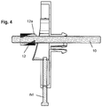
Figur 4- einen Längsschnitt der Befestigungsvorrichtung gemäß
Figur 3 .
- Figure 1
- a longitudinal section of the rear end of a free-hanging toilet;
- Figure 2
- an enlarged longitudinal section of the view
Figure 1 with the fastening device in the installed position; - Figure 3
- a perspective view of the fastening device; and
- Figure 4
- a longitudinal section of the fastening device according to
Figure 3 .
Gleiche oder gleichwirkende Teile sind mit denselben Bezugszeichen versehen.The same or equivalent parts are provided with the same reference numerals.
Das vorgeschlagene WC wird im Wesentlichen gebildet durch ein in seiner Gesamtheit mit 2 bezeichnetes WC bzw. einen WC-Körper, vorzugsweise aus Keramik, in das bzw. in den rückseitig ein als Spülwasserstutzen 4 ausgebildeter Spülwasseranschluss eingesetzt ist zum Zuführen von Spülwasser aus einem in einer hinter der Wand angeordneten und mit der Spülwasserstutzen 4 über einen nicht dargestelltes Spülrohr verbundenen Spülkasten, der als verdeckter Spülkasten in der Wand verbaut ist. Über diesen Spülwasseranschluss 4 strömt Spülwasser im Rahmen einer Spülung in einen durch das WC 2 definierten Spülraum 2a und aus diesem über einen im unteren Ende des WCs 2 ausgebildeten Siphon 2b durch den als Ablaufstutzen 6 ausgebildeten Abwasseranschluss in ein Abflussrohr. Der Siphon 2b verhindert somit in bekannter Weise durch das in der unteren Krümmung nach der Spülung enthaltene Wasser das Ausströmen von Gerüchen aus der Abwasserleitung in das WC 2.The proposed toilet is essentially formed by a WC designated in its entirety with 2 or a toilet body, preferably made of ceramic, into or into the back of which a flushing water connection designed as a flushing
Der Spülwasserstutzen 4 und der Ablaufstutzen 6 sind jeweils im Wesentlichen als hohlzylindrische Spritzgussteile ausgebildet, die mit ihren - in Einbaulage gesehenen - Vorderenden mittels einer kreisringförmigen Dichtmanschette rückseitig in entsprechend ausgebildete Aufnahmen an der Rückseite des WC-Körpers 2 lösbar und dichtend eingesetzt sind.The rinsing
Der Halter 8a ist ausgebildet zur Befestigung an der Innenseite einer Rückwand 2d des WCs 2. Vorliegend ist dieser ausgebildet als kastenförmiges Kunststoffspritzgussteil, das - in der Draufsicht - eine länglich, rechteckige Gestalt aufweist. Dabei definiert eine Bodenplatte des Halters 8a eine Montageebene, von der sich seitliche Längs- und stirnseitige Stirnwände quer zur Ebene der Bodenplatte erstrecken zur Bildung eines geschlossenen, die Bodenplatte umschließenden Rahmens. Dieser Rahmen des Halters 8a definiert mit der Bodenplatte einen Aufnahmeraum zur längsverschieblichen Aufnahme des Klemmkeils 8b, der Aufnahmeraum ist also länger als der Klemmkeil 8b ausgebildet. In der Mitte der Bodenplatte weist der Halter 8a eine Durchgangsöffnung auf, von der sich an der Rückseite der Bodenplatte mehrere Rastlaschen 8c entgegen des durch die Seitenwände definierten Aufnahmeraums des Halters 8a konzentrisch um die Durchgangsöffnung erstrecken. Mittels dieser Rastlaschen kann der Halter 8a innenseitig mit einer korrespondierend ausgebildeten Durchgangsöffnung in der Rückwand 2d des WC 2 lösbar zur Befestigung eingeschnappt werden.The
Ein mit seinem proximalen Ende in die Wand eingeschraubter Befestigungsbolzen 10 weist an seinem distalen, also dem von der Wand entfernten Ende, ein Außengewinde auf, auf das ein als Rändelmutter 12 ausgebildetes Halteelement aufgeschraubt ist. Der Befestigungsbolzen 10 kann mit aufgeschraubter Rändelmutter 12 durch die Durchgangsöffnung des Halters 8a gesteckt werden, um so bereits eine Vorfixierung des WC-Körpers 2 an der Wand zu bewirken, weil in dieser Position das in Einbaulage obere Stirnende des rechteckig ausgebildeten Klemmkeils 8b auf der Oberseite des Befestigungsbolzens 10 aufliegt und das WC 2 durch die Rändelmutter 12 aufgrund seines Eigengewichts gehalten wird.A
Am in Einbaulage unteren Stirnende weist der Halter 8a eine Durchgangsöffnung mit einem Innengewinde auf, in welche als Schraubelement eine Einstellschraube 8d eingedreht ist, die mit ihrem Vorderende drehbeweglich befestigt ist in dem unteren Ende des Klemmkeils 8b, so dass dieser relativ zu dem Halter 8a durch die Drehung der Einstellschraube 8d verstellbar ist.At the lower end in the installed position, the
Der Klemmkeil 8b besteht - in der Draufsicht - aus einem rechteckig geschlossenen Rahmen, der vorzugsweise aus Metall oder Kunststoff gefertigt ist und dessen in Einbaulage auf dem Halter 8a gleitende Rückseite eben und dessen Vorderseite mit einer Steigung der Vorderkanten ausgebildet ist, welche vom in den
Erkennbar ist für die Montage bzw. Feineinstellung nur ein Zugang von unten erforderlich. Die Seiten und der obere Abschnitt des WCs 2 können also vollständig verschlossen sein, was erhebliche hygienische und reinigungstechnische Vorteile bietet.Obviously, only access from below is required for assembly or fine adjustment. The sides and the upper section of the
Die Erfindung lässt sich besonders gut für Dusch-WCs einsetzen, da diese für die zusätzliche Spülarmatur mehr Bauraum benötigen, welcher durch die Erfindung leichter zugänglich ist.The invention can be used particularly well for shower toilets, since they require more installation space for the additional flush fitting, which is more easily accessible due to the invention.
Da bei der Erfindung das Verspannen bzw. Anziehen von unterhalb der Keramik erfolgen kann, sind insofern keine Öffnungen bzw. vergrößerte Öffnungen innerhalb der Wand des WC-Köpers bzw. der Keramik für den Zugang erforderlich.Since in the invention the bracing or tightening can take place from below the ceramic, no openings or enlarged openings within the wall of the toilet body or the ceramic are required for access.
Beim typischen Anwendungsfall zur Befestigung eines freihängenden WCs an einer Wand werden zunächst zwei Befestigungsbolzen in entsprechende Gewindebuchsen in der Wand im Abstand zueinander eingeschraubt, das vorkonfektionierte und mit zwei erfindungsgemäßen Befestigungseinrichtungen bestückte WC wird auf die Befestigungsbolzen aufgesetzt und sodann von unten gegen die Wand verspannt. Insofern betrifft die Erfindung auch ein Einbauset bestehend aus mindestens zwei Gewindebolzen und zwei zuvor beschriebenen Befestigungseinrichtungen.In the typical application for attaching a free-hanging toilet to a wall, two fastening bolts are first screwed into corresponding threaded bushes in the wall at a distance from one another, the pre-assembled and equipped with two fastening devices according to the invention is placed on the fastening bolts and then braced against the wall from below. In this respect, the invention also relates to an installation set consisting of at least two threaded bolts and two fastening devices described above.
- 22nd
- WC-KörperToilet body
- 2a2a
- SpülraumWashroom
- 2b2 B
- PrimärsiphonPrimary siphon
- 2c2c
- Absatzparagraph
- 2d2d
- RückwandBack wall
- 44th
- SpülwasserzufuhrRinse water supply
- 66
- AblaufstutzenDrain connector
- 88th
- BefestigungsvorrichtungFastening device
- 8a8a
- Halterholder
- 8b8b
- KlemmkeilWedge
- 8c8c
- RastlascheLocking tab
- 8d8d
- EinstellschraubeAdjusting screw
- 8e8e
- GleitflächeSliding surface
- 1010th
- BefestigungsbolzenMounting bolts
- 1212th
- RändelmutterKnurled nut
- 12a12a
- GleitflächeSliding surface
Claims (6)
- Unit comprising a holding element (12) and a fastening device (8) for fastening a freely suspended WC on a fixing bolt (10) provided on a wall, the WC comprising a rear wall which defines a fixing plane and is adapted to abut against the wall, the fastening device (8) comprising a holder (8a) that can be fixed to the rear wall and is adapted to receive the fastening bolt (10) in the installed position, a clamping element as well as a screw element (8d) for fixing the holder (8a) to the fastening bolt (10) in the installation position, wherein the clamping element designed as a clamping wedge (8b) is connectible to the fastening bolt (10), wherein the holder (8a) is designed for displaceably receiving and guiding the clamping wedge (8b), wherein a linear transmission is formed between the holder (8a) and clamping wedge (8b), which is actuated via the screw element (8d) extending transversely to the longitudinal axis of the fastening bolt, wherein the unit comprises a holding element (12) which can be connected to the fastening bolt (10), wherein the clamping wedge (8b) and the holding element (12) have sliding surfaces (8e, 12a) corresponding to one another, characterized in that the holder (8a) has a passage for passing through the fastening bolt (10) and the holding element (12) connected to the fastening bolt for pre-fixing the WC (2), wherein for pre-fixing the WC (2) with the holder (8a) fixed on the inside of its rear wall can be pushed onto the fixing bolt with the holding element (12) connected thereto until the mutually corresponding sliding surfaces (8e, 12a) of the holding element (12) and of the clamping part (8b) abut one another, wherein, after the pre-fixing, the clamping wedge (8b) is adjustable via the screw element (8d) to the holder (8a) fixed stationarily to the WC, causing a movement of the WC through the sliding surfaces (8e, 12a) sliding on one another between the holding element and the clamping wedge.
- Unit according to claim 1, characterized in that the holding element (12) is designed as a knurled screw (12).
- Unit according to one of the preceding claims, characterized in that the holder (8a) is designed for detachable fastening to the rear wall of the WC (2).
- Unit according to one of the preceding claims, characterized in that the screw element (8d) comprises quick adjustment means.
- Unit according to claim 4, characterized in that the quick adjustment means comprise a bracket.
- Installation set for fixing a freely suspended WC to a wall, comprising two fixing bolts which can be screwed into the wall and two units according to one of the claims 1 to 5.
Applications Claiming Priority (1)
| Application Number | Priority Date | Filing Date | Title |
|---|---|---|---|
| DE102013223702 | 2013-11-20 |
Publications (2)
| Publication Number | Publication Date |
|---|---|
| EP2876222A1 EP2876222A1 (en) | 2015-05-27 |
| EP2876222B1 true EP2876222B1 (en) | 2020-03-11 |
Family
ID=52020945
Family Applications (1)
| Application Number | Title | Priority Date | Filing Date |
|---|---|---|---|
| EP14194205.2A Active EP2876222B1 (en) | 2013-11-20 | 2014-11-20 | Unit comprising a fastening device for a wall-mounted toilet and a holding element. |
Country Status (1)
| Country | Link |
|---|---|
| EP (1) | EP2876222B1 (en) |
Families Citing this family (2)
| Publication number | Priority date | Publication date | Assignee | Title |
|---|---|---|---|---|
| EP3401452B1 (en) * | 2017-05-12 | 2020-07-29 | Geberit International AG | Fitting device for a bathroom item |
| FR3112179B1 (en) * | 2020-07-02 | 2022-07-22 | Aff Groupe | FIXING DEVICE |
Family Cites Families (6)
| Publication number | Priority date | Publication date | Assignee | Title |
|---|---|---|---|---|
| SE360898B (en) | 1971-11-05 | 1973-10-08 | Ifoe Ab | |
| DE9004324U1 (en) | 1990-04-14 | 1990-06-21 | Keramag Keramische Werke Ag, 4030 Ratingen, De | |
| EP0504587A3 (en) * | 1991-03-19 | 1993-02-24 | Keramag Keramische Werke Aktiengesellschaft | Device for fixing a sanitary unit |
| NL9401071A (en) | 1994-06-28 | 1996-02-01 | Koninkl Sphinx Nv | Mounting assembly for a wall-mounted lavatory |
| ITPD20020048A1 (en) * | 2002-02-26 | 2003-08-26 | Fischer Italia Srl Unipersonal | HIDDEN FIXING DEVICE FOR HANGING TYPE OBJECTS. |
| ITPD20070401A1 (en) | 2007-12-04 | 2009-06-05 | Fischer Italia S R L Uniperson | FIXING DEVICE, PARTICULARLY FOR SANITARY WALLS SUSPENDED |
-
2014
- 2014-11-20 EP EP14194205.2A patent/EP2876222B1/en active Active
Non-Patent Citations (1)
| Title |
|---|
| None * |
Also Published As
| Publication number | Publication date |
|---|---|
| EP2876222A1 (en) | 2015-05-27 |
Similar Documents
| Publication | Publication Date | Title |
|---|---|---|
| EP1863976B1 (en) | Device and method for fixing a sanitary object to a supporting surface using an assembly plate | |
| EP2333169B1 (en) | Sanitary installation and mount for fixing a sanitary installation | |
| EP3746607B1 (en) | System comprising a connecting device and a sanitary appliance | |
| EP0485757A1 (en) | Construction kit for manufacture of handles, hand vails, guard barriers, small furniture and the like | |
| EP2876222B1 (en) | Unit comprising a fastening device for a wall-mounted toilet and a holding element. | |
| EP3296474B1 (en) | Fixing device for a wall-hung item of sanitaryware and fixing arrangement | |
| EP0786562A1 (en) | Wall support on a mounting frame | |
| EP3733986B1 (en) | Assembly frame for a sanitary article with electrical box | |
| EP1260639B1 (en) | Wall support on a mounting frame for sanitary devices | |
| EP0731226B1 (en) | Element for the assembly of a sanitary installation in front of a wall | |
| EP3401452B1 (en) | Fitting device for a bathroom item | |
| EP1510625B1 (en) | Fixing device for wall mounting of sanitary elements | |
| DE19953682A1 (en) | Washstand with side struts uses transparent plastics profile plate joined at two points to channelled struts as joined to plate by level-adjustable metal bar anchorable in strut channels. | |
| EP2407603B1 (en) | Assembly device with an assembly frame and method for assembling such an assembly device | |
| AT522573B1 (en) | Arrangement for the installation and assembly of a wash basin | |
| WO2015180963A1 (en) | Mounting device | |
| EP0731225B1 (en) | Cross-bar for an element for the assembly in front of a wall | |
| EP3296473B1 (en) | Fixing device for a wall-hung item of sanitaryware, fixing arrangement and method for demounting a wall-hung item of sanitaryware | |
| DE102009010428A1 (en) | Device for connecting e.g. prefabricated elements of washbasin at profile rails, has clamping arrangement for producing connection between profile rails and hook-shaped element such that device is fixed at rails in radial direction | |
| DE202009002502U1 (en) | Vanity unit with console | |
| DE19510228A1 (en) | Fastening device of a cistern | |
| EP2868820B1 (en) | Toilet cistern arrangement | |
| DE102004055558A1 (en) | Profiled rail and supporting frame e.g. for sanitary installations, has in cross section exterior surfaces with retaining slots run lengthwise covering partial number of exterior surfaces | |
| DE202004017027U1 (en) | Installation kit for the assembly of sanitary components comprises a first assembly hollow profile and adapter elements for connecting the first hollow profile with a standard light profile | |
| DE102022131506A1 (en) | Mobile flood protection system |
Legal Events
| Date | Code | Title | Description |
|---|---|---|---|
| PUAI | Public reference made under article 153(3) epc to a published international application that has entered the european phase |
Free format text: ORIGINAL CODE: 0009012 |
|
| 17P | Request for examination filed |
Effective date: 20141120 |
|
| AK | Designated contracting states |
Kind code of ref document: A1 Designated state(s): AL AT BE BG CH CY CZ DE DK EE ES FI FR GB GR HR HU IE IS IT LI LT LU LV MC MK MT NL NO PL PT RO RS SE SI SK SM TR |
|
| AX | Request for extension of the european patent |
Extension state: BA ME |
|
| R17P | Request for examination filed (corrected) |
Effective date: 20151127 |
|
| RBV | Designated contracting states (corrected) |
Designated state(s): AL AT BE BG CH CY CZ DE DK EE ES FI FR GB GR HR HU IE IS IT LI LT LU LV MC MK MT NL NO PL PT RO RS SE SI SK SM TR |
|
| STAA | Information on the status of an ep patent application or granted ep patent |
Free format text: STATUS: EXAMINATION IS IN PROGRESS |
|
| 17Q | First examination report despatched |
Effective date: 20170804 |
|
| GRAP | Despatch of communication of intention to grant a patent |
Free format text: ORIGINAL CODE: EPIDOSNIGR1 |
|
| STAA | Information on the status of an ep patent application or granted ep patent |
Free format text: STATUS: GRANT OF PATENT IS INTENDED |
|
| INTG | Intention to grant announced |
Effective date: 20191025 |
|
| GRAS | Grant fee paid |
Free format text: ORIGINAL CODE: EPIDOSNIGR3 |
|
| GRAA | (expected) grant |
Free format text: ORIGINAL CODE: 0009210 |
|
| STAA | Information on the status of an ep patent application or granted ep patent |
Free format text: STATUS: THE PATENT HAS BEEN GRANTED |
|
| AK | Designated contracting states |
Kind code of ref document: B1 Designated state(s): AL AT BE BG CH CY CZ DE DK EE ES FI FR GB GR HR HU IE IS IT LI LT LU LV MC MK MT NL NO PL PT RO RS SE SI SK SM TR |
|
| REG | Reference to a national code |
Ref country code: GB Ref legal event code: FG4D Free format text: NOT ENGLISH |
|
| REG | Reference to a national code |
Ref country code: CH Ref legal event code: EP |
|
| REG | Reference to a national code |
Ref country code: AT Ref legal event code: REF Ref document number: 1243302 Country of ref document: AT Kind code of ref document: T Effective date: 20200315 |
|
| REG | Reference to a national code |
Ref country code: DE Ref legal event code: R096 Ref document number: 502014013780 Country of ref document: DE |
|
| REG | Reference to a national code |
Ref country code: IE Ref legal event code: FG4D Free format text: LANGUAGE OF EP DOCUMENT: GERMAN |
|
| REG | Reference to a national code |
Ref country code: NL Ref legal event code: FP |
|
| PG25 | Lapsed in a contracting state [announced via postgrant information from national office to epo] |
Ref country code: FI Free format text: LAPSE BECAUSE OF FAILURE TO SUBMIT A TRANSLATION OF THE DESCRIPTION OR TO PAY THE FEE WITHIN THE PRESCRIBED TIME-LIMIT Effective date: 20200311 Ref country code: NO Free format text: LAPSE BECAUSE OF FAILURE TO SUBMIT A TRANSLATION OF THE DESCRIPTION OR TO PAY THE FEE WITHIN THE PRESCRIBED TIME-LIMIT Effective date: 20200611 Ref country code: RS Free format text: LAPSE BECAUSE OF FAILURE TO SUBMIT A TRANSLATION OF THE DESCRIPTION OR TO PAY THE FEE WITHIN THE PRESCRIBED TIME-LIMIT Effective date: 20200311 |
|
| PG25 | Lapsed in a contracting state [announced via postgrant information from national office to epo] |
Ref country code: LV Free format text: LAPSE BECAUSE OF FAILURE TO SUBMIT A TRANSLATION OF THE DESCRIPTION OR TO PAY THE FEE WITHIN THE PRESCRIBED TIME-LIMIT Effective date: 20200311 Ref country code: SE Free format text: LAPSE BECAUSE OF FAILURE TO SUBMIT A TRANSLATION OF THE DESCRIPTION OR TO PAY THE FEE WITHIN THE PRESCRIBED TIME-LIMIT Effective date: 20200311 Ref country code: GR Free format text: LAPSE BECAUSE OF FAILURE TO SUBMIT A TRANSLATION OF THE DESCRIPTION OR TO PAY THE FEE WITHIN THE PRESCRIBED TIME-LIMIT Effective date: 20200612 Ref country code: HR Free format text: LAPSE BECAUSE OF FAILURE TO SUBMIT A TRANSLATION OF THE DESCRIPTION OR TO PAY THE FEE WITHIN THE PRESCRIBED TIME-LIMIT Effective date: 20200311 Ref country code: BG Free format text: LAPSE BECAUSE OF FAILURE TO SUBMIT A TRANSLATION OF THE DESCRIPTION OR TO PAY THE FEE WITHIN THE PRESCRIBED TIME-LIMIT Effective date: 20200611 |
|
| REG | Reference to a national code |
Ref country code: LT Ref legal event code: MG4D |
|
| PG25 | Lapsed in a contracting state [announced via postgrant information from national office to epo] |
Ref country code: SK Free format text: LAPSE BECAUSE OF FAILURE TO SUBMIT A TRANSLATION OF THE DESCRIPTION OR TO PAY THE FEE WITHIN THE PRESCRIBED TIME-LIMIT Effective date: 20200311 Ref country code: IS Free format text: LAPSE BECAUSE OF FAILURE TO SUBMIT A TRANSLATION OF THE DESCRIPTION OR TO PAY THE FEE WITHIN THE PRESCRIBED TIME-LIMIT Effective date: 20200711 Ref country code: LT Free format text: LAPSE BECAUSE OF FAILURE TO SUBMIT A TRANSLATION OF THE DESCRIPTION OR TO PAY THE FEE WITHIN THE PRESCRIBED TIME-LIMIT Effective date: 20200311 Ref country code: EE Free format text: LAPSE BECAUSE OF FAILURE TO SUBMIT A TRANSLATION OF THE DESCRIPTION OR TO PAY THE FEE WITHIN THE PRESCRIBED TIME-LIMIT Effective date: 20200311 Ref country code: SM Free format text: LAPSE BECAUSE OF FAILURE TO SUBMIT A TRANSLATION OF THE DESCRIPTION OR TO PAY THE FEE WITHIN THE PRESCRIBED TIME-LIMIT Effective date: 20200311 Ref country code: RO Free format text: LAPSE BECAUSE OF FAILURE TO SUBMIT A TRANSLATION OF THE DESCRIPTION OR TO PAY THE FEE WITHIN THE PRESCRIBED TIME-LIMIT Effective date: 20200311 Ref country code: CZ Free format text: LAPSE BECAUSE OF FAILURE TO SUBMIT A TRANSLATION OF THE DESCRIPTION OR TO PAY THE FEE WITHIN THE PRESCRIBED TIME-LIMIT Effective date: 20200311 Ref country code: PT Free format text: LAPSE BECAUSE OF FAILURE TO SUBMIT A TRANSLATION OF THE DESCRIPTION OR TO PAY THE FEE WITHIN THE PRESCRIBED TIME-LIMIT Effective date: 20200805 |
|
| REG | Reference to a national code |
Ref country code: DE Ref legal event code: R097 Ref document number: 502014013780 Country of ref document: DE |
|
| PLBE | No opposition filed within time limit |
Free format text: ORIGINAL CODE: 0009261 |
|
| STAA | Information on the status of an ep patent application or granted ep patent |
Free format text: STATUS: NO OPPOSITION FILED WITHIN TIME LIMIT |
|
| PG25 | Lapsed in a contracting state [announced via postgrant information from national office to epo] |
Ref country code: ES Free format text: LAPSE BECAUSE OF FAILURE TO SUBMIT A TRANSLATION OF THE DESCRIPTION OR TO PAY THE FEE WITHIN THE PRESCRIBED TIME-LIMIT Effective date: 20200311 Ref country code: IT Free format text: LAPSE BECAUSE OF FAILURE TO SUBMIT A TRANSLATION OF THE DESCRIPTION OR TO PAY THE FEE WITHIN THE PRESCRIBED TIME-LIMIT Effective date: 20200311 Ref country code: DK Free format text: LAPSE BECAUSE OF FAILURE TO SUBMIT A TRANSLATION OF THE DESCRIPTION OR TO PAY THE FEE WITHIN THE PRESCRIBED TIME-LIMIT Effective date: 20200311 |
|
| 26N | No opposition filed |
Effective date: 20201214 |
|
| PG25 | Lapsed in a contracting state [announced via postgrant information from national office to epo] |
Ref country code: SI Free format text: LAPSE BECAUSE OF FAILURE TO SUBMIT A TRANSLATION OF THE DESCRIPTION OR TO PAY THE FEE WITHIN THE PRESCRIBED TIME-LIMIT Effective date: 20200311 Ref country code: PL Free format text: LAPSE BECAUSE OF FAILURE TO SUBMIT A TRANSLATION OF THE DESCRIPTION OR TO PAY THE FEE WITHIN THE PRESCRIBED TIME-LIMIT Effective date: 20200311 |
|
| PG25 | Lapsed in a contracting state [announced via postgrant information from national office to epo] |
Ref country code: MC Free format text: LAPSE BECAUSE OF FAILURE TO SUBMIT A TRANSLATION OF THE DESCRIPTION OR TO PAY THE FEE WITHIN THE PRESCRIBED TIME-LIMIT Effective date: 20200311 |
|
| REG | Reference to a national code |
Ref country code: CH Ref legal event code: PL |
|
| PG25 | Lapsed in a contracting state [announced via postgrant information from national office to epo] |
Ref country code: LU Free format text: LAPSE BECAUSE OF NON-PAYMENT OF DUE FEES Effective date: 20201120 |
|
| REG | Reference to a national code |
Ref country code: BE Ref legal event code: MM Effective date: 20201130 |
|
| PG25 | Lapsed in a contracting state [announced via postgrant information from national office to epo] |
Ref country code: LI Free format text: LAPSE BECAUSE OF NON-PAYMENT OF DUE FEES Effective date: 20201130 Ref country code: CH Free format text: LAPSE BECAUSE OF NON-PAYMENT OF DUE FEES Effective date: 20201130 |
|
| PG25 | Lapsed in a contracting state [announced via postgrant information from national office to epo] |
Ref country code: IE Free format text: LAPSE BECAUSE OF NON-PAYMENT OF DUE FEES Effective date: 20201120 |
|
| PG25 | Lapsed in a contracting state [announced via postgrant information from national office to epo] |
Ref country code: MT Free format text: LAPSE BECAUSE OF FAILURE TO SUBMIT A TRANSLATION OF THE DESCRIPTION OR TO PAY THE FEE WITHIN THE PRESCRIBED TIME-LIMIT Effective date: 20200311 Ref country code: CY Free format text: LAPSE BECAUSE OF FAILURE TO SUBMIT A TRANSLATION OF THE DESCRIPTION OR TO PAY THE FEE WITHIN THE PRESCRIBED TIME-LIMIT Effective date: 20200311 |
|
| PG25 | Lapsed in a contracting state [announced via postgrant information from national office to epo] |
Ref country code: MK Free format text: LAPSE BECAUSE OF FAILURE TO SUBMIT A TRANSLATION OF THE DESCRIPTION OR TO PAY THE FEE WITHIN THE PRESCRIBED TIME-LIMIT Effective date: 20200311 Ref country code: AL Free format text: LAPSE BECAUSE OF FAILURE TO SUBMIT A TRANSLATION OF THE DESCRIPTION OR TO PAY THE FEE WITHIN THE PRESCRIBED TIME-LIMIT Effective date: 20200311 |
|
| PG25 | Lapsed in a contracting state [announced via postgrant information from national office to epo] |
Ref country code: BE Free format text: LAPSE BECAUSE OF NON-PAYMENT OF DUE FEES Effective date: 20201130 |
|
| PGFP | Annual fee paid to national office [announced via postgrant information from national office to epo] |
Ref country code: DE Payment date: 20230127 Year of fee payment: 9 |
|
| P01 | Opt-out of the competence of the unified patent court (upc) registered |
Effective date: 20230527 |
|
| PGFP | Annual fee paid to national office [announced via postgrant information from national office to epo] |
Ref country code: NL Payment date: 20231122 Year of fee payment: 10 |
|
| PGFP | Annual fee paid to national office [announced via postgrant information from national office to epo] |
Ref country code: GB Payment date: 20231123 Year of fee payment: 10 |
|
| PGFP | Annual fee paid to national office [announced via postgrant information from national office to epo] |
Ref country code: TR Payment date: 20231113 Year of fee payment: 10 Ref country code: FR Payment date: 20231122 Year of fee payment: 10 Ref country code: AT Payment date: 20231117 Year of fee payment: 10 |