EP2873823A1 - Abgasreinigungssystem für einen Verbrennungsmotor - Google Patents
Abgasreinigungssystem für einen Verbrennungsmotor Download PDFInfo
- Publication number
- EP2873823A1 EP2873823A1 EP20140193252 EP14193252A EP2873823A1 EP 2873823 A1 EP2873823 A1 EP 2873823A1 EP 20140193252 EP20140193252 EP 20140193252 EP 14193252 A EP14193252 A EP 14193252A EP 2873823 A1 EP2873823 A1 EP 2873823A1
- Authority
- EP
- European Patent Office
- Prior art keywords
- scr catalyst
- ammonia
- temperature
- amount
- temperature rise
- Prior art date
- Legal status (The legal status is an assumption and is not a legal conclusion. Google has not performed a legal analysis and makes no representation as to the accuracy of the status listed.)
- Granted
Links
Images


Classifications
-
- F—MECHANICAL ENGINEERING; LIGHTING; HEATING; WEAPONS; BLASTING
- F01—MACHINES OR ENGINES IN GENERAL; ENGINE PLANTS IN GENERAL; STEAM ENGINES
- F01N—GAS-FLOW SILENCERS OR EXHAUST APPARATUS FOR MACHINES OR ENGINES IN GENERAL; GAS-FLOW SILENCERS OR EXHAUST APPARATUS FOR INTERNAL COMBUSTION ENGINES
- F01N13/00—Exhaust or silencing apparatus characterised by constructional features ; Exhaust or silencing apparatus, or parts thereof, having pertinent characteristics not provided for in, or of interest apart from, groups F01N1/00 - F01N5/00, F01N9/00, F01N11/00
- F01N13/009—Exhaust or silencing apparatus characterised by constructional features ; Exhaust or silencing apparatus, or parts thereof, having pertinent characteristics not provided for in, or of interest apart from, groups F01N1/00 - F01N5/00, F01N9/00, F01N11/00 having two or more separate purifying devices arranged in series
- F01N13/0093—Exhaust or silencing apparatus characterised by constructional features ; Exhaust or silencing apparatus, or parts thereof, having pertinent characteristics not provided for in, or of interest apart from, groups F01N1/00 - F01N5/00, F01N9/00, F01N11/00 having two or more separate purifying devices arranged in series the purifying devices are of the same type
-
- F—MECHANICAL ENGINEERING; LIGHTING; HEATING; WEAPONS; BLASTING
- F01—MACHINES OR ENGINES IN GENERAL; ENGINE PLANTS IN GENERAL; STEAM ENGINES
- F01N—GAS-FLOW SILENCERS OR EXHAUST APPARATUS FOR MACHINES OR ENGINES IN GENERAL; GAS-FLOW SILENCERS OR EXHAUST APPARATUS FOR INTERNAL COMBUSTION ENGINES
- F01N13/00—Exhaust or silencing apparatus characterised by constructional features ; Exhaust or silencing apparatus, or parts thereof, having pertinent characteristics not provided for in, or of interest apart from, groups F01N1/00 - F01N5/00, F01N9/00, F01N11/00
- F01N13/009—Exhaust or silencing apparatus characterised by constructional features ; Exhaust or silencing apparatus, or parts thereof, having pertinent characteristics not provided for in, or of interest apart from, groups F01N1/00 - F01N5/00, F01N9/00, F01N11/00 having two or more separate purifying devices arranged in series
-
- F—MECHANICAL ENGINEERING; LIGHTING; HEATING; WEAPONS; BLASTING
- F01—MACHINES OR ENGINES IN GENERAL; ENGINE PLANTS IN GENERAL; STEAM ENGINES
- F01N—GAS-FLOW SILENCERS OR EXHAUST APPARATUS FOR MACHINES OR ENGINES IN GENERAL; GAS-FLOW SILENCERS OR EXHAUST APPARATUS FOR INTERNAL COMBUSTION ENGINES
- F01N3/00—Exhaust or silencing apparatus having means for purifying, rendering innocuous, or otherwise treating exhaust
- F01N3/02—Exhaust or silencing apparatus having means for purifying, rendering innocuous, or otherwise treating exhaust for cooling, or for removing solid constituents of, exhaust
- F01N3/021—Exhaust or silencing apparatus having means for purifying, rendering innocuous, or otherwise treating exhaust for cooling, or for removing solid constituents of, exhaust by means of filters
- F01N3/023—Exhaust or silencing apparatus having means for purifying, rendering innocuous, or otherwise treating exhaust for cooling, or for removing solid constituents of, exhaust by means of filters using means for regenerating the filters, e.g. by burning trapped particles
- F01N3/025—Exhaust or silencing apparatus having means for purifying, rendering innocuous, or otherwise treating exhaust for cooling, or for removing solid constituents of, exhaust by means of filters using means for regenerating the filters, e.g. by burning trapped particles using fuel burner or by adding fuel to exhaust
- F01N3/0253—Exhaust or silencing apparatus having means for purifying, rendering innocuous, or otherwise treating exhaust for cooling, or for removing solid constituents of, exhaust by means of filters using means for regenerating the filters, e.g. by burning trapped particles using fuel burner or by adding fuel to exhaust adding fuel to exhaust gases
-
- F—MECHANICAL ENGINEERING; LIGHTING; HEATING; WEAPONS; BLASTING
- F01—MACHINES OR ENGINES IN GENERAL; ENGINE PLANTS IN GENERAL; STEAM ENGINES
- F01N—GAS-FLOW SILENCERS OR EXHAUST APPARATUS FOR MACHINES OR ENGINES IN GENERAL; GAS-FLOW SILENCERS OR EXHAUST APPARATUS FOR INTERNAL COMBUSTION ENGINES
- F01N3/00—Exhaust or silencing apparatus having means for purifying, rendering innocuous, or otherwise treating exhaust
- F01N3/02—Exhaust or silencing apparatus having means for purifying, rendering innocuous, or otherwise treating exhaust for cooling, or for removing solid constituents of, exhaust
- F01N3/021—Exhaust or silencing apparatus having means for purifying, rendering innocuous, or otherwise treating exhaust for cooling, or for removing solid constituents of, exhaust by means of filters
- F01N3/033—Exhaust or silencing apparatus having means for purifying, rendering innocuous, or otherwise treating exhaust for cooling, or for removing solid constituents of, exhaust by means of filters in combination with other devices
- F01N3/035—Exhaust or silencing apparatus having means for purifying, rendering innocuous, or otherwise treating exhaust for cooling, or for removing solid constituents of, exhaust by means of filters in combination with other devices with catalytic reactors, e.g. catalysed diesel particulate filters
-
- F—MECHANICAL ENGINEERING; LIGHTING; HEATING; WEAPONS; BLASTING
- F01—MACHINES OR ENGINES IN GENERAL; ENGINE PLANTS IN GENERAL; STEAM ENGINES
- F01N—GAS-FLOW SILENCERS OR EXHAUST APPARATUS FOR MACHINES OR ENGINES IN GENERAL; GAS-FLOW SILENCERS OR EXHAUST APPARATUS FOR INTERNAL COMBUSTION ENGINES
- F01N3/00—Exhaust or silencing apparatus having means for purifying, rendering innocuous, or otherwise treating exhaust
- F01N3/08—Exhaust or silencing apparatus having means for purifying, rendering innocuous, or otherwise treating exhaust for rendering innocuous
- F01N3/10—Exhaust or silencing apparatus having means for purifying, rendering innocuous, or otherwise treating exhaust for rendering innocuous by thermal or catalytic conversion of noxious components of exhaust
- F01N3/101—Three-way catalysts
-
- F—MECHANICAL ENGINEERING; LIGHTING; HEATING; WEAPONS; BLASTING
- F01—MACHINES OR ENGINES IN GENERAL; ENGINE PLANTS IN GENERAL; STEAM ENGINES
- F01N—GAS-FLOW SILENCERS OR EXHAUST APPARATUS FOR MACHINES OR ENGINES IN GENERAL; GAS-FLOW SILENCERS OR EXHAUST APPARATUS FOR INTERNAL COMBUSTION ENGINES
- F01N3/00—Exhaust or silencing apparatus having means for purifying, rendering innocuous, or otherwise treating exhaust
- F01N3/08—Exhaust or silencing apparatus having means for purifying, rendering innocuous, or otherwise treating exhaust for rendering innocuous
- F01N3/10—Exhaust or silencing apparatus having means for purifying, rendering innocuous, or otherwise treating exhaust for rendering innocuous by thermal or catalytic conversion of noxious components of exhaust
- F01N3/18—Exhaust or silencing apparatus having means for purifying, rendering innocuous, or otherwise treating exhaust for rendering innocuous by thermal or catalytic conversion of noxious components of exhaust characterised by methods of operation; Control
- F01N3/20—Exhaust or silencing apparatus having means for purifying, rendering innocuous, or otherwise treating exhaust for rendering innocuous by thermal or catalytic conversion of noxious components of exhaust characterised by methods of operation; Control specially adapted for catalytic conversion ; Methods of operation or control of catalytic converters
- F01N3/2006—Periodically heating or cooling catalytic reactors, e.g. at cold starting or overheating
- F01N3/2033—Periodically heating or cooling catalytic reactors, e.g. at cold starting or overheating using a fuel burner or introducing fuel into exhaust duct
-
- F—MECHANICAL ENGINEERING; LIGHTING; HEATING; WEAPONS; BLASTING
- F01—MACHINES OR ENGINES IN GENERAL; ENGINE PLANTS IN GENERAL; STEAM ENGINES
- F01N—GAS-FLOW SILENCERS OR EXHAUST APPARATUS FOR MACHINES OR ENGINES IN GENERAL; GAS-FLOW SILENCERS OR EXHAUST APPARATUS FOR INTERNAL COMBUSTION ENGINES
- F01N3/00—Exhaust or silencing apparatus having means for purifying, rendering innocuous, or otherwise treating exhaust
- F01N3/08—Exhaust or silencing apparatus having means for purifying, rendering innocuous, or otherwise treating exhaust for rendering innocuous
- F01N3/10—Exhaust or silencing apparatus having means for purifying, rendering innocuous, or otherwise treating exhaust for rendering innocuous by thermal or catalytic conversion of noxious components of exhaust
- F01N3/18—Exhaust or silencing apparatus having means for purifying, rendering innocuous, or otherwise treating exhaust for rendering innocuous by thermal or catalytic conversion of noxious components of exhaust characterised by methods of operation; Control
- F01N3/20—Exhaust or silencing apparatus having means for purifying, rendering innocuous, or otherwise treating exhaust for rendering innocuous by thermal or catalytic conversion of noxious components of exhaust characterised by methods of operation; Control specially adapted for catalytic conversion ; Methods of operation or control of catalytic converters
- F01N3/2066—Selective catalytic reduction [SCR]
- F01N3/208—Control of selective catalytic reduction [SCR], e.g. dosing of reducing agent
-
- F—MECHANICAL ENGINEERING; LIGHTING; HEATING; WEAPONS; BLASTING
- F01—MACHINES OR ENGINES IN GENERAL; ENGINE PLANTS IN GENERAL; STEAM ENGINES
- F01N—GAS-FLOW SILENCERS OR EXHAUST APPARATUS FOR MACHINES OR ENGINES IN GENERAL; GAS-FLOW SILENCERS OR EXHAUST APPARATUS FOR INTERNAL COMBUSTION ENGINES
- F01N9/00—Electrical control of exhaust gas treating apparatus
- F01N9/002—Electrical control of exhaust gas treating apparatus of filter regeneration, e.g. detection of clogging
-
- F—MECHANICAL ENGINEERING; LIGHTING; HEATING; WEAPONS; BLASTING
- F01—MACHINES OR ENGINES IN GENERAL; ENGINE PLANTS IN GENERAL; STEAM ENGINES
- F01N—GAS-FLOW SILENCERS OR EXHAUST APPARATUS FOR MACHINES OR ENGINES IN GENERAL; GAS-FLOW SILENCERS OR EXHAUST APPARATUS FOR INTERNAL COMBUSTION ENGINES
- F01N2610/00—Adding substances to exhaust gases
- F01N2610/02—Adding substances to exhaust gases the substance being ammonia or urea
-
- F—MECHANICAL ENGINEERING; LIGHTING; HEATING; WEAPONS; BLASTING
- F01—MACHINES OR ENGINES IN GENERAL; ENGINE PLANTS IN GENERAL; STEAM ENGINES
- F01N—GAS-FLOW SILENCERS OR EXHAUST APPARATUS FOR MACHINES OR ENGINES IN GENERAL; GAS-FLOW SILENCERS OR EXHAUST APPARATUS FOR INTERNAL COMBUSTION ENGINES
- F01N2610/00—Adding substances to exhaust gases
- F01N2610/03—Adding substances to exhaust gases the substance being hydrocarbons, e.g. engine fuel
-
- F—MECHANICAL ENGINEERING; LIGHTING; HEATING; WEAPONS; BLASTING
- F01—MACHINES OR ENGINES IN GENERAL; ENGINE PLANTS IN GENERAL; STEAM ENGINES
- F01N—GAS-FLOW SILENCERS OR EXHAUST APPARATUS FOR MACHINES OR ENGINES IN GENERAL; GAS-FLOW SILENCERS OR EXHAUST APPARATUS FOR INTERNAL COMBUSTION ENGINES
- F01N2900/00—Details of electrical control or of the monitoring of the exhaust gas treating apparatus
- F01N2900/06—Parameters used for exhaust control or diagnosing
- F01N2900/16—Parameters used for exhaust control or diagnosing said parameters being related to the exhaust apparatus, e.g. particulate filter or catalyst
- F01N2900/1602—Temperature of exhaust gas apparatus
-
- F—MECHANICAL ENGINEERING; LIGHTING; HEATING; WEAPONS; BLASTING
- F01—MACHINES OR ENGINES IN GENERAL; ENGINE PLANTS IN GENERAL; STEAM ENGINES
- F01N—GAS-FLOW SILENCERS OR EXHAUST APPARATUS FOR MACHINES OR ENGINES IN GENERAL; GAS-FLOW SILENCERS OR EXHAUST APPARATUS FOR INTERNAL COMBUSTION ENGINES
- F01N2900/00—Details of electrical control or of the monitoring of the exhaust gas treating apparatus
- F01N2900/06—Parameters used for exhaust control or diagnosing
- F01N2900/16—Parameters used for exhaust control or diagnosing said parameters being related to the exhaust apparatus, e.g. particulate filter or catalyst
- F01N2900/1622—Catalyst reducing agent absorption capacity or consumption amount
-
- F—MECHANICAL ENGINEERING; LIGHTING; HEATING; WEAPONS; BLASTING
- F01—MACHINES OR ENGINES IN GENERAL; ENGINE PLANTS IN GENERAL; STEAM ENGINES
- F01N—GAS-FLOW SILENCERS OR EXHAUST APPARATUS FOR MACHINES OR ENGINES IN GENERAL; GAS-FLOW SILENCERS OR EXHAUST APPARATUS FOR INTERNAL COMBUSTION ENGINES
- F01N2900/00—Details of electrical control or of the monitoring of the exhaust gas treating apparatus
- F01N2900/06—Parameters used for exhaust control or diagnosing
- F01N2900/18—Parameters used for exhaust control or diagnosing said parameters being related to the system for adding a substance into the exhaust
- F01N2900/1806—Properties of reducing agent or dosing system
- F01N2900/1812—Flow rate
-
- Y—GENERAL TAGGING OF NEW TECHNOLOGICAL DEVELOPMENTS; GENERAL TAGGING OF CROSS-SECTIONAL TECHNOLOGIES SPANNING OVER SEVERAL SECTIONS OF THE IPC; TECHNICAL SUBJECTS COVERED BY FORMER USPC CROSS-REFERENCE ART COLLECTIONS [XRACs] AND DIGESTS
- Y02—TECHNOLOGIES OR APPLICATIONS FOR MITIGATION OR ADAPTATION AGAINST CLIMATE CHANGE
- Y02T—CLIMATE CHANGE MITIGATION TECHNOLOGIES RELATED TO TRANSPORTATION
- Y02T10/00—Road transport of goods or passengers
- Y02T10/10—Internal combustion engine [ICE] based vehicles
- Y02T10/12—Improving ICE efficiencies
-
- Y—GENERAL TAGGING OF NEW TECHNOLOGICAL DEVELOPMENTS; GENERAL TAGGING OF CROSS-SECTIONAL TECHNOLOGIES SPANNING OVER SEVERAL SECTIONS OF THE IPC; TECHNICAL SUBJECTS COVERED BY FORMER USPC CROSS-REFERENCE ART COLLECTIONS [XRACs] AND DIGESTS
- Y02—TECHNOLOGIES OR APPLICATIONS FOR MITIGATION OR ADAPTATION AGAINST CLIMATE CHANGE
- Y02T—CLIMATE CHANGE MITIGATION TECHNOLOGIES RELATED TO TRANSPORTATION
- Y02T10/00—Road transport of goods or passengers
- Y02T10/10—Internal combustion engine [ICE] based vehicles
- Y02T10/40—Engine management systems
Definitions
- the present invention relates to an exhaust gas purification system for an internal combustion engine.
- an NOx selective reduction catalyst (hereinafter, also referred to simply as an "SCR catalyst") which purifies (removes or reduces) NOx contained in an exhaust gas from an internal combustion engine by using ammonia as a reducing agent.
- SCR catalyst an NOx selective reduction catalyst
- a reducing agent supply valve which serves to supply ammonia or a precursor (e.g., urea) of ammonia into the exhaust gas.
- Such two SCR catalysts may be arranged in series with each other in an exhaust passage of an internal combustion engine.
- only one reducing agent supply valve is arranged at the upstream side of an upstream side SCR catalyst (hereinafter, also referred to as a first SCR catalyst).
- Ammonia having flowed out from the first SCR catalyst is adsorbed to a downstream side SCR catalyst (hereinafter, also referred to as a second SCR catalyst), and hence, NOx can be reduced in the second SCR catalyst, too.
- the two SCR catalysts which are arranged in series with each other, the NOx which was not reduced in the first SCR catalyst can be reduced in the second SCR catalyst.
- the first SCR catalyst and the second SCR catalyst are different in temperature, etc., so that even if one of the SCR catalysts is in a state where NOx can not be reduced, the other SCR catalyst may be in a state where NOx can be reduced. Accordingly, the rate of NOx reduction (hereinafter, also referred to as an NOx reduction rate) of a system as a whole can be improved by the provision of the two SCR catalysts in series with each other.
- the filter supporting the SCR catalyst is also referred to as an SCRF.
- the filter regeneration processing is to oxidize and remove the PM deposited on the SCRF.
- the filter regeneration processing is achieved by supplying fuel (HC) to a pre-stage catalyst having an oxidation function which is arranged in the exhaust passage at the upstream side of the SCRF.
- the exhaust gas flowing into the SCRF will be heated by the heat of oxidation. For that reason, the temperature of the SCRF can be raised to a filter regeneration temperature at which the oxidation of the PM is promoted.
- the amount of NOx to be generated by the oxidation of ammonia may become larger than the amount of NOx to be reduced by ammonia. For this reason, even if the amount of ammonia to be supplied is increased, the NOx reduction rate decreases.
- the temperature of the first SCR catalyst is high, the temperature of the second SCR catalyst may be low.
- the ammonia to be supplied will be oxidized in the first SCR catalyst. For this reason, it will become difficult to supply ammonia to the second SCR catalyst, so that ammonia will become short or insufficient in the second SCR catalyst.
- the present invention has been made in view of the problems as mentioned above, and the object of the invention is that in cases where a plurality of SCR catalysts are provided in series with one another, a decrease in the NOx reduction rate of a system as a whole is suppressed when an upstream side SCR catalyst is at a high temperature.
- the present invention resides in an exhaust gas purification system for an internal combustion engine which is provided with:
- the temperature of said first SCR catalyst goes up by carrying out the temperature rise control.
- the temperature rise control is not limited to the control of raising the temperature of said first SCR catalyst, for the purpose of said first SCR catalyst.
- the temperature of the exhaust gas may be caused to rise when particulate matter trapped in the filter is removed.
- the temperature of the first SCR catalyst or the second SCR catalyst, or the temperature of a further catalyst which is provided in the exhaust passage is caused to rise
- the temperature of the exhaust gas may be raised.
- the rise in temperature of such a catalyst is carried out in order to cause it to arrive at its activation temperature quickly, or in order to recover sulfur poisoning or HC poisoning of the catalyst. In this manner, the temperature rise control should just be such that the temperature of the first SCR catalyst goes up irrespective of its purpose.
- the predetermined temperature can be set to a temperature at which ammonia is oxidized.
- the predetermined temperature may be a temperature at which the particulate matter is oxidized.
- the temperature of the second SCR catalyst may become less than the predetermined temperature.
- ammonia or the precursor of ammonia is supplied when the temperature of the first SCR catalyst is equal to or higher than the predetermined temperature, the ammonia is oxidized in the first SCR catalyst, so it is difficult to cause the ammonia to be adsorbed to the second SCR catalyst.
- said control device starts the temperature rise control at the time when the amount of ammonia adsorbed by the second SCR catalyst is equal to or larger than the temperature rise start threshold value.
- the temperature rise control may be inhibited at the time when the amount of ammonia adsorbed by the second SCR catalyst is less than the temperature rise start threshold value.
- the temperature rise start threshold value is an amount of ammonia sufficient to reduce NOx in the second SCR catalyst in the course of carrying out the temperature rise control.
- the temperature rise start threshold value may also be set to an amount of ammonia which is smaller than an amount of adsorption of ammonia at the time when the ammonia is saturated in the second SCR catalyst (hereinafter, referred to as a saturated amount of adsorption of ammonia), and which is an amount of ammonia with a margin with respect to the saturated amount of ammonia. Because the saturated amount of adsorption of ammonia changes according to the temperature of the second SCR catalyst, the temperature rise start threshold value may be set in such a manner that ammonia does not desorb from the second SCR catalyst, when the temperature rise control is being carried out.
- Said control device can make the amount of ammonia or the amount of the precursor thereof to be supplied from said supply device to said first SCR catalyst larger at the time when there is a request for carrying out said temperature rise control and before said temperature rise control is carried out, than at the time when there is no request for carrying out said temperature rise control.
- Said control device may make a determination as to whether there is a request for carrying out the temperature rise control.
- the case where there is a request for carrying out the temperature rise control means that there is a need to carry out the temperature rise control, for example, a case where a predetermined condition for carrying out the temperature rise control is satisfied.
- a predetermined condition for carrying out the temperature rise control For example, when the temperature rise control is not carried out, it can be said that in cases where the amount of particulate matter (PM) trapped by the filter exceeds an allowable value, or in cases where the exhaust gas purification ability of the system becomes lower than an allowable range, there is a request for carrying out the temperature rise control. Then, when there is a request for carrying out the temperature rise control, it is desirable to start the temperature rise control quickly.
- PM particulate matter
- said control device does not start the temperature rise control at times other than when the amount of ammonia adsorbed by the second SCR catalyst is equal to or larger than the temperature rise start threshold value.
- the amount of ammonia or the amount of the precursor thereof to be supplied to the first SCR catalyst is made relatively large at the time when there is a request for carrying out the temperature rise control, the amount of ammonia or the amount of the precursor thereof flowing out from the first SCR catalyst will increase. In that case, the amount of adsorption of ammonia in the second SCR catalyst can be made to increase quickly. For this reason, the amount of ammonia having been adsorbed by the second SCR catalyst will quickly reach the temperature rise start threshold value. Accordingly, after there has been a request for carrying out the temperature rise control, it becomes possible to quickly start the temperature rise control.
- said control device can make the amount of ammonia or the amount of the precursor thereof to be supplied from said supply device to said first SCR catalyst larger in the case where the amount of ammonia adsorbed by said second SCR catalyst is less than said temperature rise start threshold value, than in the case where the amount of ammonia adsorbed by said second SCR catalyst is equal to or larger than said temperature rise start threshold value.
- the amount of ammonia adsorbed by the second SCR catalyst is equal to or larger than said temperature rise start threshold value, it is not necessary to supply ammonia or the precursor thereof.
- the amount of ammonia adsorbed to the second SCR catalyst can be caused to arrive at the temperature rise start threshold value quickly, by making relatively large the amount of ammonia or the precursor thereof to be supplied to the first SCR catalyst. As a result of this, the temperature rise control can be started quickly.
- said control device can adjust the amount of ammonia or the amount of the precursor thereof to be supplied from said supply device to said first SCR catalyst in such a manner that the ammonia or the precursor thereof flows out from said first SCR catalyst.
- Ammonia can not be supplied to the second SCR catalyst, unless ammonia flows out from the first SCR catalyst.
- Ammonia can be caused to flow out from the first SCR catalyst, for example, by supplying an amount of ammonia more than that which can be adsorbed by the first SCR catalyst.
- ammonia or the precursor thereof can be caused to flow out from the first SCR catalyst by supplying ammonia or the precursor thereof to the first SCR catalyst.
- ammonia can be caused to be adsorbed to the second SCR catalyst.
- ammonia flows out from the first SCR catalyst depending on conditions.
- said control device can stop the supply of ammonia or the precursor thereof from said supply device to said first SCR catalyst.
- the temperature of the first SCR catalyst becomes high, whereby ammonia therein is oxidized to generate NOx.
- ammonia or the precursor thereof to the first SCR catalyst By stopping the supply of ammonia or the precursor thereof to the first SCR catalyst at the time when the temperature rise control is carried out, it is possible to suppress NOx from being generated in the first SCR catalyst. As a result of this, the NOx reduction rate of the system as a whole can be improved.
- said control device can resume the supply of ammonia or the precursor thereof from said supply device to said first SCR catalyst, in cases where the temperature of said first SCR catalyst is lower than said predetermined temperature, and in cases where the amount of ammonia adsorbed by said second SCR catalyst is less than said temperature rise start threshold value.
- ammonia or the precursor thereof may be supplied to the first SCR catalyst in such a manner that ammonia does not flow out from the first SCR catalyst. If the temperature of the first SCR catalyst goes up again, ammonia will desorb from the first SCR catalyst, so that it will be supplied to the second SCR catalyst.
- said control device can carry out temperature drop control in which the temperature of said first SCR catalyst is caused to drop lower than said predetermined temperature, in cases where the temperature of said first SCR catalyst is equal to or larger than said predetermined temperature, and in cases where the amount of ammonia adsorbed by said second SCR catalyst is equal to or less than an ammonia supply threshold value at which the adsorption of ammonia is caused to be resumed, and can resume the supply of ammonia or the precursor thereof from said supply device to said first SCR catalyst, after the temperature of said first SCR catalyst becomes lower than the predetermined temperature by means of the temperature drop control.
- said control device can make the temperature of the first SCR catalyst drop in order to cause ammonia to be desorbed to the second SCR catalyst.
- the temperature drop control may only simply stop or inhibit the temperature rise control, or may cause the temperature of the exhaust gas to drop in a positive manner. By doing in this manner, it is possible to suppress ammonia from becoming short in the second SCR catalyst, thus making it possible to suppress the reduction rate of NOx from decreasing to a remarkable extent.
- a decrease in the NOx reduction rate of a system as a whole can be suppressed when an upstream side SCR catalyst is at a high temperature.
- an exhaust gas purification system for an internal combustion engine according to the present invention is applied to a diesel engine for driving a vehicle.
- the internal combustion engine related to the present invention is not limited to a diesel engine, but may be a gasoline engine, etc.
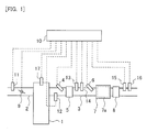
- Fig. 1 is a view showing the schematic construction of intake and exhaust systems of an internal combustion engine according to an embodiment.
- the internal combustion engine 1 is a diesel engine for driving a vehicle.
- An intake passage 2 and an exhaust passage 3 are connected to the internal combustion engine 1.
- the air flow meter 11 serves to detect an amount of intake air sucked into the internal combustion engine 1.
- the throttle valve 9 serves to adjust the amount of intake air sucked into the internal combustion engine 1.
- a first exhaust gas temperature sensor 12 In the exhaust passage 3, there are arranged a first exhaust gas temperature sensor 12, a fuel addition valve 4, a pre-stage catalyst 5, a first NOx sensor 13, a second exhaust gas temperature sensor 14, a reducing agent supply valve 6, an SCRF 7, a second SCR catalyst 8, a second NOx sensor 15, and a third exhaust gas temperature sensor 16, sequentially from an upstream side along the flow of an exhaust gas.
- the pre-stage catalyst 5 is an oxidation catalyst.
- the pre-stage catalyst 5 may be a catalyst other than the oxidation catalyst, as long as it has an oxidation function.
- the pre-stage catalyst 5 may be a three-way catalyst, for example.
- the fuel addition valve 4 adds fuel (HC) into the exhaust gas.
- the SCRF 7 is constructed such that a first SCR catalyst 7a is supported by a wall flow type filter which serves to trap particulate matter in the exhaust gas.
- the first SCR catalyst 7a and the second SCR catalyst 8 adsorb ammonia, and reduce the NOx in the exhaust gas by using the ammonia as a reducing agent.
- the reducing agent supply valve 6 supplies ammonia into the exhaust gas.
- a precursor of ammonia may be supplied, in place of ammonia.
- the precursor of ammonia there can be mentioned urea, for example. When urea is hydrolyzed by the heat of the exhaust gas, ammonia is generated.
- the ammonia or the precursor thereof may be supplied in any state of gas, liquid and solid. A part of the ammonia is adsorbed by the first SCR catalyst 7a.
- the reducing agent supply valve 6 corresponds to a supply device in the present invention.
- the first exhaust gas temperature sensor 12, the second exhaust gas temperature sensor 14, and the third exhaust gas temperature sensor 16 are each a sensor for detecting the temperature of exhaust gas.
- the first exhaust gas temperature sensor 12 detects the temperature of the exhaust gas which flows out from the internal combustion engine 1 or detects the temperature of the exhaust gas which flows into the pre-stage catalyst 5.
- the second exhaust gas temperature sensor 14 detects the temperature of the exhaust gas which flows out from the pre-stage catalyst 5 or detects the temperature of the exhaust gas which flows into the SCRF 7.
- the third exhaust gas temperature sensor 16 detects the temperature of the exhaust gas which flows out from the second SCR catalyst 8.
- the first NOx sensor 13 and the second NOx sensor 15 are each a sensor for detecting the concentration of NOx in the exhaust gas.
- the first NOx sensor 13 detects the concentration of NOx in the exhaust gas flowing into the SCRF 7.
- the second NOx sensor 15 detects the concentration of NOx in the exhaust gas flowing out from the second SCR catalyst 8. All of these sensors are not necessary required, but some of them can be provided as appropriate.
- a fuel injection valve 17 for directly injecting fuel into a corresponding cylinder.
- An electronic control unit (ECU) 10 is provided in combination with the internal combustion engine 1.
- the ECU 10 is electrically connected to a variety of kinds of sensors such as the air flow meter 11, the first exhaust gas temperature sensor 12, the first NOx sensor 13, the second exhaust gas temperature sensor 14, the second NOx sensor 15, the third exhaust gas temperature sensor 16, and so on. Then, output signals of these various kinds of sensors are inputted to the ECU 10.
- the ECU 10 estimates the flow rate of the exhaust gas in the exhaust passage 3 based on the output value of the air flow meter 11.
- the ECU 10 estimates the temperature of the pre-stage catalyst 5 based on the output value of the first exhaust gas temperature sensor 12, the temperature of the SCRF 7 (i.e., the temperature of the first SCR catalyst 7a) based on the output value of the second exhaust gas temperature sensor 14, and the temperature of the second SCR catalyst 8 based on the output value of the third exhaust gas temperature sensor 16.
- the throttle valve 9, the fuel addition valve 4, the reducing agent supply valve 6, and the fuel injection valves 17 are electrically connected to the ECU 10. Then, these parts are controlled by means of the ECU 10.
- the ECU 10 corresponds to a control device in the present invention.
- unburnt fuel can also be discharged from the internal combustion engine 1.
- the ECU 10 can also supply fuel to the pre-stage catalyst 5 in the internal combustion engine 1 by carrying out post injection in which fuel is injected at the timing at which the fuel injected from each fuel injection valve 17 is discharged into the exhaust passage 3 in an unburnt state without being combusted.
- filter regeneration processing is carried out by means of the ECU 10 in order to remove the PM deposited in the SCRF 7.
- temperature rise control is carried out in which the temperature of the exhaust gas is caused to go up in the pre-stage catalyst 5 by supplying fuel to the pre-stage catalyst 5.
- the supply of fuel to the pre-stage catalyst 5 is carried out by means of at least one of the addition of fuel from the fuel addition valve 4, and the post injection.
- the execution of the filter regeneration processing may also be requested.
- the amount of PM deposition in the SCRF 7 can be estimated based on the histories of the amount of fuel injection in the internal combustion engine 1, the flow rate of the exhaust gas flowing into the SCRF 7, the temperature of the SCRF 7, and so on.
- Fig. 2 is a view showing the relation between the temperature of the SCR catalyst and the rate of NOx reduction therein.
- the NOx reduction rate of the SCR catalyst changes with the temperature thereof. Then, there exists a temperature at which the NOx reduction rate of the SCR catalyst becomes the highest, and the NOx reduction rate decreases therefrom, whether the temperature becomes higher or lower than this temperature.
- a range indicated by a "first SCR” in Fig. 2 is a temperature range of the first SCR catalyst 7a when the filter regeneration processing is carried out.
- the second SCR catalyst 8 is a temperature range of the second SCR catalyst 8 when the filter regeneration processing is carried out.
- the first SCR catalyst 7a is closer to the pre-stage catalyst 5 than the second SCR catalyst 8, and hence, is higher in temperature than the second SCR catalyst 8.
- the PM is oxidized to generate heat, so that the temperature of the first SCR catalyst 7a becomes higher than the temperature of the second SCR catalyst 8.
- the temperature of the first SCR catalyst 7a is high, and so, the NOx reduction rate thereof becomes low.
- the temperature of the first SCR catalyst 7a at the time when the filter regeneration processing is carried out goes up to a temperature at which ammonia is oxidized and changed into NOx.
- an amount of NOx flowing out from the SCRF 7 can become more than an amount of NOx flowing into the SCRF 7.
- the NOx reduction rate of the SCRF 7 becomes a negative value.
- the ammonia having been adsorbed thereto desorbs therefrom due to high temperature, so that the reducing agent for reducing NOx runs short. For these reasons, the NOx reduction rate of the first SCR catalyst 7a at the time when filter regeneration processing is carried out becomes low.
- the temperature of the second SCR catalyst 8 at the time when the filter regeneration processing is carried out becomes low, as compared with the temperature of the first SCR catalyst 7a. For this reason, the NOx reduction rate of the second SCR catalyst 8 at the time when the filter regeneration processing is carried out becomes relatively high.
- an amount of ammonia equal to or larger than a threshold value A has been caused to be adsorbed to the second SCR catalyst 8 in advance.
- the filter regeneration processing may be carried out, after waiting until the amount of ammonia equal to or larger than the threshold value A is adsorbed to the second SCR catalyst 8.
- the filter regeneration processing may be inhibited, until the amount of ammonia equal to or larger than the threshold value A is adsorbed to the second SCR catalyst 8.
- the threshold value A referred to herein is an amount of adsorption of ammonia which is required in order to reduce NOx in the second SCR catalyst 8 during the execution of the filter regeneration processing.
- the threshold value A corresponds to a temperature rise start threshold value in the present invention.
- Fig. 3 is a view showing the relation between an amount of adsorption of ammonia in the SCR catalyst and the NOx reduction rate thereof. Until the amount of adsorption of ammonia increases to some extent, the larger the amount of adsorption of ammonia in the SCR catalyst, the higher becomes the NOx reduction rate thereof. On the other hand, when the amount of adsorption of ammonia in the SCR catalyst increases to some extent, the NOx reduction rate thereof does not substantially change even if the amount of adsorption of ammonia in the SCR catalyst further increases. Thus, the threshold value A is set to a value smaller than a range where the NOx reduction rate does not substantially change.
- the threshold value A is set to an amount of adsorption of ammonia in the SCR catalyst at which the NOx reduction rate thereof also changes in accordance with a change in the amount of adsorption of ammonia, and with which the NOx reduction rate of the SCR catalyst becomes relatively high.
- a threshold value C will be described later.
- the threshold value A is set to a value which is smaller than the saturated amount of adsorption of ammonia in the second SCR catalyst 8, and which has a margin with respect to the saturated amount of adsorption of ammonia in the second SCR catalyst 8. For example, during the execution of the filter regeneration processing, ammonia desorbs from the first SCR catalyst 7a, and hence, it is preferable that ammonia can be adsorbed in the second SCR catalyst 8.
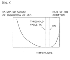
- Fig. 4 is a view showing the relation between the temperature, the saturated amount of adsorption of ammonia (solid line), and the rate of ammonia oxidation (alternate long and short dash line), of the SCR catalyst.
- the rate of ammonia oxidation is a ratio of an amount of ammonia which is oxidized to change into NOx with respect to an amount of ammonia supplied.
- TPM in Fig. 4 is a temperature at which the oxidation of particulate matter (PM) begins. The higher the temperature of the SCR catalyst, the smaller becomes the saturated amount of adsorption of ammonia, and when the temperature of the SCR catalyst is equal to or higher than a threshold value TA, the saturated amount of adsorption of ammonia becomes zero.
- This threshold value TA is a maximum (the highest) temperature at which the SCR catalyst can adsorb ammonia.
- the temperature of the first SCR catalyst 7a will become equal to or higher than TPM, but the temperature of the second SCR catalyst 8 becomes equal to or lower than the threshold value TA.
- the amount of adsorption of ammonia in the second SCR catalyst 8 is estimated by the ECU 10.
- the amount of adsorption of ammonia in the second SCR catalyst 8 is obtained, for example, by subtracting an amount of ammonia consumed by the second SCR catalyst 8 from an amount of ammonia which flows into the second SCR catalyst 8.
- the amount of ammonia flowing into the second SCR catalyst 8 is equal to an amount of ammonia which flows out from the first SCR catalyst 7a.
- the amount of ammonia flowing out from the first SCR catalyst 7a is in the correlation with an engine operating condition and the rate of NOx reduction in the first SCR catalyst 7a, and hence, such a correlation has been obtained by experiments or simulations in advance, and stored in the ECU 10.
- an ammonia sensor for detecting ammonia may be mounted on the exhaust passage 3 at a location between the first SCR catalyst 7a and the second SCR catalyst 8, and the amount of ammonia flowing out from the first SCR catalyst 7a may be calculated based on a detected value of the ammonia sensor.
- the amount of ammonia consumed by the second SCR catalyst 8 is in the correlation with the engine operating condition and the rate of NOx reduction in the second SCR catalyst 8, and hence, such a correlation has been obtained by experiments or simulations in advance, and stored in the ECU 10.
- the rates of NOx reduction in the first SCR catalyst 7a and the second SCR catalyst 8 are in the correlation with the temperatures of the individual catalysts and an amount of intake air, so that they can be estimated based on the temperatures of the individual catalysts and the amount of intake air.
- the rates of NOx reduction in the individual catalysts can also be obtained based on an estimated value of the concentration of NOx discharged from the internal combustion engine 1, and the concentrations of NOx detected by and the first NOx sensor 13 and the second NOx sensor 15, respectively.
- Fig. 5 is a flow chart showing a flow or routine of the filter regeneration processing according to this embodiment of the present invention. This routine is carried out by means of the ECU 10 in a repeated manner at each predetermined time interval.
- step S101 it is determined whether there is any request for the execution of the filter regeneration processing.
- the temperature rise control is carried out in which the temperature of the exhaust gas flowing into the SCRF 7 becomes a temperature at which ammonia is oxidized. For example, each time a predetermined period of time elapses after the execution of the last filter regeneration processing ends, the execution of the filter regeneration processing is requested. In addition, each time the vehicle with the internal combustion engine 1 mounted thereon travels a predetermined travel distance, the execution of the filter regeneration processing may also instead be requested. Moreover, each time the amount of PM deposition in the SCRF 7 reaches a predetermined amount of deposition, the execution of the filter regeneration processing may also be requested. In cases where an affirmative determination is made in step S101, the routine advances to step S102, whereas in cases where a negative determination is made, this routine is ended.
- step S102 it is determined whether the amount of adsorption of ammonia in the second SCR catalyst 8 is equal to or larger than the threshold value A.
- the threshold value A has been obtained through experiments, simulations or the like in advance. In cases where an affirmative determination is made in step S102, the routine advances to step S103, whereas in cases where a negative determination is made, this routine is ended.
- step S103 the filter regeneration processing is carried out. As a result of this, in the first SCR catalyst 7a, it becomes difficult to reduce NOx.
- step S104 it is determined whether the regeneration of the filter has been completed. In cases where the amount of the PM having been trapped by the SCRF 7 has decreased to a sufficient extent, the regeneration of the filter is completed.
- a determination may be made that the regeneration of the filter has been completed. In cases where an affirmative determination is made in step S104, this routine is ended, whereas in cases where a negative determination is made, the processing of step S104 is carried out again. That is, the execution of the step S104 is carried out until the regeneration of the filter is completed.
- the temperature of the first SCR catalyst 7a becomes high during the execution of the filter regeneration processing, but a similar consideration can be made in a case where the temperature of the first SCR catalyst 7a becomes high for other reasons.
- fuel may be supplied to the pre-stage catalyst 5. That is, in order to activate a catalyst arranged at the downstream side of the pre-stage catalyst 5, or in order to eliminate the sulfur poisoning of an NOx storage reduction catalyst in the case where the NOx storage reduction catalyst is provided, fuel may be supplied to the pre-catalyst 5. That is, in these cases, too, the temperature rise control is carried out. In these cases, if the temperature of the first SCR catalyst 7a goes up to a temperature at which ammonia is oxidized, ammonia may have been caused to be adsorbed to the second SCR catalyst 8 before the execution of the temperature rise control.
- the amount of ammonia to be supplied to the first SCR catalyst 7a is caused to increase in a positive manner. According to this, the amount of ammonia having been adsorbed to the second SCR catalyst 8 is caused to increase quickly.
- the other devices, parts and so on are the same as those in the first embodiment, so the explanation thereof is omitted.
- the ammonia not having been adsorbed in the first SCR catalyst 7a, or ammonia having desorbed from the first SCR catalyst 7a is adsorbed to the second SCR catalyst 8. If the first SCR catalyst 7a is in a state to be able to adsorb ammonia, the amount of ammonia flowing out from the first SCR catalyst 7a is small, so that the amount of ammonia to be adsorbed to the second SCR catalyst 8 also becomes small. For this reason, it may take time until the amount of ammonia having been adsorbed by the second SCR catalyst 8 becomes equal to or more than the threshold value A.
- the amount of ammonia to be supplied to the first SCR catalyst 7a is made to be larger, as compared with the time when there is no request for carrying out the filter regeneration processing.
- the amount of ammonia flowing out from the first SCR catalyst 7a can be caused to increase, by making higher the concentration of ammonia in the exhaust gas.
- the concentration of ammonia in the exhaust gas may also be made high by increasing the amount of supply of ammonia by making a period of time to supply the ammonia long, or the concentration of ammonia in the exhaust gas may also be made high by increasing the amount of supply of ammonia by increasing the amount of supply of ammonia per unit time.
- the amount of ammonia flowing out from the first SCR catalyst 7a increases, so that the amount of ammonia to be adsorbed to the second SCR catalyst 8 also increases.
- ammonia may be forced to flow out from the first SCR catalyst 7a in a positive manner, by supplying to the first SCR catalyst 7a an amount of ammonia more than that at which ammonia is saturated in the first SCR catalyst 7a.
- Fig. 6 is a flow chart showing a flow or routine of the filter regeneration processing according to this second embodiment of the present invention. This routine is carried out by means of the ECU 10 in a repeated manner at each predetermined time interval.
- This routine is carried out by means of the ECU 10 in a repeated manner at each predetermined time interval.
- step S201 in cases where an affirmative determination is made in step S101, the routine advances to step S201.
- the amount of ammonia supplied from the reducing agent supply valve 6 is caused to increase in step S201. That is, the amount of supply of ammonia at the time when there is a request for the execution of the filter regeneration processing is made to be larger than the amount of supply of ammonia at the time when there is no request for the execution of the filter regeneration processing.
- the amount of supply of ammonia at the time when there is no request for the execution of the filter regeneration processing is decided according to an amount of NOx flowing into the first SCR catalyst 7a.
- the increase in the amount of supply of ammonia is continued until an affirmative determination is made in step S102. That is, in cases where a negative determination is made in step S102, the routine returns to step S201.
- an optimal value of the amount of supply of ammonia after the increase may have been obtained in advance through experiments, simulations, or the like.
- step S202 the supply of ammonia is stopped. At this time, a sufficient amount of ammonia has been adsorbed to the second SCR catalyst 8, even if the supply of ammonia is stopped, NOx can be reduced by the ammonia which has been adsorbed to the second SCR catalyst 8.
- step S202 instead of stopping the supply of ammonia, the amount of supply of ammonia may be decreased. That is, the amount of ammonia to be supplied to the first SCR catalyst 7a may also be made smaller than that in the case where the amount of ammonia having been adsorbed by the second SCR catalyst 8 is less than the threshold value A.
- step S104 in cases where an affirmative determination is made in step S104, i.e., in cases where it is determined that the regeneration of the filter was completed, the routine goes to step S203, where the supply of ammonia is resumed.
- step S203 ammonia is supplied by setting the amount of supply thereof to that at the time when there is no request for the execution of the filter regeneration processing.
- the amount of ammonia flowing out from the first SCR catalyst 7a is caused to increase in a positive manner, so that ammonia can be caused to be adsorbed to the second SCR catalyst 8 quickly. Accordingly, it is possible to quickly start the filter regeneration processing.
- ammonia is not supplied during the execution of the filter regeneration processing, and hence, there is a fear that all the ammonia adsorbed to the second SCR catalyst 8 may be consumed. At this time, ammonia has not been adsorbed to the first SCR catalyst 7a, either, so the rate of NOx reduction of the system as a whole will decrease. Accordingly, in this third embodiment, even during the execution of the filter regeneration processing, in cases where the temperature of the first SCR catalyst 7a is a temperature at which ammonia can be adsorbed, or a temperature at which ammonia is not oxidized, ammonia is supplied from the reducing agent supply valve 6.
- the threshold value B can be made to be an amount of ammonia which is required for reducing NOx in the second SCR catalyst 8.
- the threshold value B may also be made to be an amount of saturated ammonia in the first SCR catalyst 7a. If ammonia has been caused to be adsorbed to the first SCR catalyst 7a, the ammonia will desorb from the first SCR catalyst 7a in an early stage of the execution of the filter regeneration processing, so that the ammonia can be supplied to the second SCR catalyst 8.
- ammonia may be supplied in such a manner as to flow out from the first SCR catalyst 7a, similar to the above-mentioned second embodiment.
- ammonia may be supplied in such a manner as to flow out from the first SCR catalyst 7a, similar to the above-mentioned second embodiment.
- the exhaust gas of low temperature flows through the SCRF 7, for example during deceleration, so that the temperature of the first SCR catalyst 7a can drop to a temperature at which it is able to adsorb ammonia.
- ammonia is not oxidized into NOx. If ammonia has been caused to be adsorbed to the first SCR catalyst 7a at this time, the ammonia will desorb from the first SCR catalyst 7a at the next time when the temperature of the SCRF 7 goes up. Then, this ammonia is adsorbed to the second SCR catalyst 8. As a result, it becomes possible to reduce NOx in the second SCR catalyst 7a.
- temperature drop control which is control to cause the temperature of the SCRF 7 to drop.
- the temperature drop control is achieved, for example, by stopping the supply of fuel to the pre-stage catalyst 5.
- the temperature drop control may also be control which stops the temperature rise control. That is, the temperature drop control is carried out by stopping or inhibiting the addition of fuel from the fuel addition valve 4, or post injection. Then, after the temperature of the SCRF 7 has dropped to a temperature at which it is able to adsorb ammonia, ammonia is supplied from the reducing agent supply valve 6.
- the threshold value C is a specific amount of adsorption of ammonia which when the amount of adsorption of ammonia becomes equal to or smaller than, the rate of NOx reduction decreases by a fixed value or more with respect to a target value. That is, the threshold value C is a specific amount of adsorption of ammonia to or below which when the amount of adsorption of ammonia decreases, the rate of NOx reduction decreases to a remarkable extent.
- the threshold value C may also be an amount of adsorption of ammonia which is smaller by a fixed value or more with respect to an amount of adsorption of ammonia which is required for the second SCR catalyst 8 to reduce NOx.
- the threshold value C corresponds to an ammonia supply threshold value in the present invention.
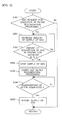
- Fig. 7 is a flow chart showing a flow or routine of the filter regeneration processing according to this third embodiment of the present invention. This routine is carried out by means of the ECU 10 in a repeated manner at each predetermined time interval.
- This routine is carried out by means of the ECU 10 in a repeated manner at each predetermined time interval.
- step S301 is processed after step S103.
- step S301 it is determined whether the amount of adsorption of ammonia in the second SCR catalyst 8 is equal to or larger than a threshold value A.
- This threshold value A is the same as the threshold value A in step S102.
- the threshold value A in step S301 can also be set to a value different from the threshold value A in step S102.
- the amount of adsorption of ammonia in the second SCR catalyst 8 is estimated based on an amount of NOx reduction after the supply of ammonia is stopped in step S202.
- the amount of NOx reduction is estimated based on an amount of NOx flowing into the second SCR catalyst 8, the temperature of the second SCR catalyst 8, and an amount of intake air in the internal combustion engine 1.
- the amount of NOx reduction in the second SCR catalyst 8 is in relation with the temperature of the second SCR catalyst 8 and the amount of intake air in the internal combustion engine 1. Then, the amount of consumption of ammonia in the second SCR catalyst 8 can be calculated from the amount of NOx flowing into the second SCR catalyst 8 and the rate of NOx reduction in the second SCR catalyst 8.
- step S102 a determination is made that the amount of adsorption of ammonia in the second SCR catalyst 8 is equal to or larger than the threshold value A, and so, the amount of adsorption of ammonia before reducing NOx is calculated as the threshold value A.
- Such a relation may have been obtained in advance through experiments, simulations or the like, and made into a map.
- step S301 In cases where an affirmative determination is made in step S301, the routine advances to step S104. Thereafter, in cases where a negative determination is made in step S104, the routine returns to step S301.
- step S301 the routine advances to step S302.
- step S302 the control to increase the amount of adsorption of ammonia in the second SCR catalyst 8 is carried out.
- Fig. 8 is a flow chart showing a flow or routine of the control to increase the amount of adsorption of ammonia in the second SCR catalyst 8, which is carried out in step S302 shown in Fig. 7 .
- This routine is carried out by means of the ECU 10 in a repeated manner at each predetermined time interval.
- step S303 it is determined whether the temperature of the SCRF 7 is equal to or lower than a threshold value TA.
- This threshold value TA is an upper limit value of the temperature at which ammonia is able to be adsorbed in the first SCR catalyst 7a.
- This threshold value TA is the same as the threshold value TA in Fig. 4 .
- step S303 it is determined whether the first SCR catalyst 7a is able to adsorb ammonia. In cases where an affirmative determination is made in step S303, the routine advances to step S304.
- step S304 an increase in the supply of ammonia is started.
- the amount of supply of ammonia in step S304 is made larger than that at times other than the execution of the filter regeneration processing. As a result of this, ammonia can be caused to be adsorbed to the first SCR catalyst 7a in a quick manner.
- the amount of supply of ammonia in step S304 may also be made to be the same as the amount of supply of ammonia at the times other than the execution of the filter regeneration processing.
- step S305 it is determined whether the amount of adsorption of ammonia in the first SCR catalyst 7a is equal to or larger than the threshold value B.
- This threshold value B may have been obtained in advance through experiments, simulations, or the like.
- step S305 the routine advances to step S202, whereas in cases where a negative determination is made, the routine returns to step S304. That is, ammonia is continued to be supplied until the amount of adsorption of ammonia in the first SCR catalyst 7a becomes equal to or more than the threshold value B.
- SCRF temperature sudden rise control which is control for causing a sudden rise in the temperature of the SCRF 7 is carried out in step S306.
- exhaust gas or unburnt fuel of high temperature is caused to discharge from the internal combustion engine 1, or fuel is added from the fuel addition valve 4, so that the temperature of the SCRF 7 is caused to go up quickly to a temperature at which particulate matter can be oxidized.
- the temperature of the first SCR catalyst 7a becomes higher than a temperature at which the first SCR catalyst 7a is able to adsorb ammonia, so that ammonia desorbs from the first SCR catalyst 7a.
- NOx can be reduced in the second SCR catalyst 8 during the execution of the filter regeneration processing.
- step S307 it is determined whether the amount of adsorption of ammonia in the second SCR catalyst 8 is equal to or less than the threshold value C.
- This threshold value C may have been obtained in advance through experiments, simulations, or the like.
- step S307 it is determined whether the rate of NOx reduction of the system as a whole will become low to a remarkable extent, if ammonia is not supplied to the second SCR catalyst 8.
- the routine advances to step S308, whereas in cases where a negative determination is made, the routine returns to step S303.
- step S308 the temperature drop control, which is the control for causing the temperature of the SCRF 7 to drop, is carried out.
- the temperature of the SCRF 7 is raised to a temperature at which it is able to adsorb ammonia. That is, in cases where the amount of adsorption of ammonia in the second SCR catalyst 8 is equal to or less than the threshold value C, ammonia is made possible to be adsorbed in the first SCR catalyst, by causing the temperature of the SCRF 7 to drop.
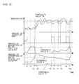
- Fig. 9 is a time chart showing changes over time of various kinds of values at the time when the filter regeneration processing according to this third embodiment of the present invention is carried out.
- a solid line in the "temperature” indicates the temperature of the first SCR catalyst 7a (the SCRF 7), and an alternate long and short dash line indicates the temperature of the second SCR catalyst 8.
- the "amount of supply of ammonia” is in relation to the amount of ammonia to be supplied to the first SCR catalyst 7a.
- a point in time T1 is that at which a request for carrying out the filter regeneration processing starts. Before the point in time T1, the amount of supply of ammonia is decided according to the concentration of NOx in the exhaust gas.
- the filter regeneration processing is not carried out, and the amount of supply of ammonia is caused to increase more than before the request for the filter regeneration processing is made.
- the amount of adsorption of ammonia in the first SCR catalyst 7a is increased due to the increase in the amount of supply of ammonia.
- the amount of adsorption of ammonia in the first SCR catalyst 7a becomes equal to or larger than the threshold value B. Accordingly, in a period of time from T2 to T3, ammonia flows out from the first SCR catalyst 7a, so that the amount of adsorption of ammonia in the second SCR catalyst 8 increases.
- the filter regeneration processing is started.
- the amount of adsorption of ammonia in the second SCR catalyst 8 becomes the threshold value A, so the supply of ammonia is stopped, and at the same time, the filter regeneration processing is started.
- the filter regeneration processing is carried out, so the temperature of the first SCR catalyst 7a and the temperature of the second SCR catalyst 8 become high. As a result of this, ammonia desorbs from the first SCR catalyst 7a, and the ammonia thus desorbed is adsorbed to the second SCR catalyst 8. Accordingly, in a period of time from T3 to T4, the amount of adsorption of ammonia in the first SCR catalyst 7a decreases, and at the same time, the amount of adsorption of ammonia in the second SCR catalyst 8 increases.
- the amount of adsorption of ammonia in the first SCR catalyst 7a becomes zero.
- the ammonia flowing out from the first SCR catalyst 7a runs short or out, and so, the ammonia to be supplied to the second SCR catalyst 8 also becomes zero.
- the ammonia having been adsorbed to the second SCR catalyst 8 is consumed by the reduction of NOx, so the amount of adsorption of ammonia in the second SCR catalyst 8 decreases.
- the temperature of the first SCR catalyst 7a becomes lower than the threshold value TA, and at the same time, the amount of adsorption of ammonia in the second SCR catalyst 8 becomes less than the threshold value A.
- ammonia can be caused to be adsorbed to the first SCR catalyst 7a. For this reason, ammonia is supplied.
- the amount of adsorption of ammonia in the first SCR catalyst 7a is increased due to this supply of ammonia.
- ammonia is supplied in such a manner as not to flow out from the first SCR catalyst 7a, and hence, the amount of adsorption of ammonia in the second SCR catalyst 8 does not increase.
- NOx is reduced in the first SCR catalyst 7a, the decrease in the amount of adsorption of ammonia in the second SCR catalyst 8 is suppressed.
- the temperature of the first SCR catalyst 7a becomes equal to or higher than the threshold value TA, so the supply of ammonia is stopped. In this period of time, ammonia desorbs from the first SCR catalyst 7a, so that the amount of adsorption of ammonia in the first SCR catalyst 7a decreases.
- the ammonia flowing out from the first SCR catalyst 7a is supplied to the second SCR catalyst 8, the amount of supply of ammonia is small, so the amount of adsorption of ammonia in the second SCR catalyst 8 decreases.
- the processing also becomes the same as in the period of time from T5 to T7.
- ammonia is supplied because the temperature of the first SCR catalyst 7a becomes lower than the threshold value TA, and at the same time, the amount of adsorption of ammonia in the second SCR catalyst 8 becomes less than the threshold value A. Then, at a point in time of T10, the amount of adsorption of ammonia in the first SCR catalyst 7a arrives at the threshold value B, so the supply of ammonia is stopped. After that, ammonia desorbs from the first SCR catalyst 7a, and the amount of adsorption of ammonia in the first SCR catalyst 7a decreases, according to which the amount of adsorption of ammonia in the second SCR catalyst 8 increases.
- ammonia can be caused to be adsorbed to the second SCR catalyst 8, thus making it possible to suppress a decrease in the rate of NOx reduction.
Landscapes
- Engineering & Computer Science (AREA)
- Chemical & Material Sciences (AREA)
- Combustion & Propulsion (AREA)
- Mechanical Engineering (AREA)
- General Engineering & Computer Science (AREA)
- Chemical Kinetics & Catalysis (AREA)
- Health & Medical Sciences (AREA)
- Toxicology (AREA)
- Materials Engineering (AREA)
- Exhaust Gas After Treatment (AREA)
- Exhaust Gas Treatment By Means Of Catalyst (AREA)
- Combined Controls Of Internal Combustion Engines (AREA)
Applications Claiming Priority (1)
| Application Number | Priority Date | Filing Date | Title |
|---|---|---|---|
| JP2013235782A JP5915623B2 (ja) | 2013-11-14 | 2013-11-14 | 内燃機関の排気浄化システム |
Publications (2)
| Publication Number | Publication Date |
|---|---|
| EP2873823A1 true EP2873823A1 (de) | 2015-05-20 |
| EP2873823B1 EP2873823B1 (de) | 2017-03-29 |
Family
ID=51900271
Family Applications (1)
| Application Number | Title | Priority Date | Filing Date |
|---|---|---|---|
| EP14193252.5A Not-in-force EP2873823B1 (de) | 2013-11-14 | 2014-11-14 | Abgasreinigungssystem für einen Verbrennungsmotor |
Country Status (2)
| Country | Link |
|---|---|
| EP (1) | EP2873823B1 (de) |
| JP (1) | JP5915623B2 (de) |
Cited By (4)
| Publication number | Priority date | Publication date | Assignee | Title |
|---|---|---|---|---|
| EP3150814A1 (de) * | 2015-10-01 | 2017-04-05 | MAN Truck & Bus AG | Verfahren zum betreiben eines abgasnachbehandlungssystems |
| EP3369904A1 (de) * | 2017-03-02 | 2018-09-05 | Toyota Jidosha Kabushiki Kaisha | Abgasreinigungsvorrichtung für einen verbrennungsmotor |
| CN110945220A (zh) * | 2017-08-10 | 2020-03-31 | 大众汽车有限公司 | 废气后处理系统和对内燃机进行废气后处理的方法 |
| US10799833B2 (en) | 2015-08-03 | 2020-10-13 | Cummins Emission Solutions Inc. | Sensor configuration for aftertreatment system including SCR on filter |
Families Citing this family (3)
| Publication number | Priority date | Publication date | Assignee | Title |
|---|---|---|---|---|
| JP6444823B2 (ja) * | 2015-07-06 | 2018-12-26 | ヤンマー株式会社 | ディーゼルエンジン |
| KR102563441B1 (ko) * | 2018-11-12 | 2023-08-03 | 현대자동차 주식회사 | 배출 가스 정화 장치 |
| JP2021127741A (ja) * | 2020-02-14 | 2021-09-02 | 株式会社Subaru | 触媒温度推定装置 |
Citations (7)
| Publication number | Priority date | Publication date | Assignee | Title |
|---|---|---|---|---|
| JP2006342734A (ja) | 2005-06-09 | 2006-12-21 | Mitsubishi Fuso Truck & Bus Corp | 排気浄化装置 |
| JP2009264181A (ja) | 2008-04-23 | 2009-11-12 | Toyota Motor Corp | 内燃機関の排気浄化装置 |
| JP2009270449A (ja) | 2008-05-01 | 2009-11-19 | Mitsubishi Fuso Truck & Bus Corp | 排気浄化装置 |
| EP2292904A2 (de) * | 2009-09-02 | 2011-03-09 | Kabushiki Kaisha Toyota Jidoshokki | Abgasreinigungsvorrichtung |
| EP2439384A1 (de) * | 2009-06-03 | 2012-04-11 | Toyota Jidosha Kabushiki Kaisha | Abgasreinigungsvorrichtung für einen verbrennungsmotor |
| JP2012154238A (ja) | 2011-01-26 | 2012-08-16 | Isuzu Motors Ltd | 排気ガス浄化システム及びディーゼルパティキュレートフィルタの強制再生方法 |
| JP2012215154A (ja) | 2011-04-01 | 2012-11-08 | Honda Motor Co Ltd | 内燃機関の排気浄化システム |
Family Cites Families (2)
| Publication number | Priority date | Publication date | Assignee | Title |
|---|---|---|---|---|
| EP2295750B1 (de) * | 2008-04-18 | 2012-05-23 | Honda Motor Co., Ltd. | Abgasreinigungsvorrichtung für verbrennungsmotor |
| JP5259653B2 (ja) * | 2010-07-23 | 2013-08-07 | 本田技研工業株式会社 | 内燃機関の排気浄化システム |
-
2013
- 2013-11-14 JP JP2013235782A patent/JP5915623B2/ja active Active
-
2014
- 2014-11-14 EP EP14193252.5A patent/EP2873823B1/de not_active Not-in-force
Patent Citations (7)
| Publication number | Priority date | Publication date | Assignee | Title |
|---|---|---|---|---|
| JP2006342734A (ja) | 2005-06-09 | 2006-12-21 | Mitsubishi Fuso Truck & Bus Corp | 排気浄化装置 |
| JP2009264181A (ja) | 2008-04-23 | 2009-11-12 | Toyota Motor Corp | 内燃機関の排気浄化装置 |
| JP2009270449A (ja) | 2008-05-01 | 2009-11-19 | Mitsubishi Fuso Truck & Bus Corp | 排気浄化装置 |
| EP2439384A1 (de) * | 2009-06-03 | 2012-04-11 | Toyota Jidosha Kabushiki Kaisha | Abgasreinigungsvorrichtung für einen verbrennungsmotor |
| EP2292904A2 (de) * | 2009-09-02 | 2011-03-09 | Kabushiki Kaisha Toyota Jidoshokki | Abgasreinigungsvorrichtung |
| JP2012154238A (ja) | 2011-01-26 | 2012-08-16 | Isuzu Motors Ltd | 排気ガス浄化システム及びディーゼルパティキュレートフィルタの強制再生方法 |
| JP2012215154A (ja) | 2011-04-01 | 2012-11-08 | Honda Motor Co Ltd | 内燃機関の排気浄化システム |
Cited By (9)
| Publication number | Priority date | Publication date | Assignee | Title |
|---|---|---|---|---|
| US10799833B2 (en) | 2015-08-03 | 2020-10-13 | Cummins Emission Solutions Inc. | Sensor configuration for aftertreatment system including SCR on filter |
| GB2556753B (en) * | 2015-08-03 | 2020-12-09 | Cummins Emission Solutions Inc | Sensor configuration for aftertreatment system including SCR on filter |
| EP3150814A1 (de) * | 2015-10-01 | 2017-04-05 | MAN Truck & Bus AG | Verfahren zum betreiben eines abgasnachbehandlungssystems |
| US9976462B2 (en) | 2015-10-01 | 2018-05-22 | Man Truck & Bus Ag | Method for the operation of an exhaust gas aftertreatment system |
| RU2736984C2 (ru) * | 2015-10-01 | 2020-11-23 | Ман Трак Унд Бас Аг | Способ и устройство эксплуатации системы нейтрализации отработавших газов |
| EP3369904A1 (de) * | 2017-03-02 | 2018-09-05 | Toyota Jidosha Kabushiki Kaisha | Abgasreinigungsvorrichtung für einen verbrennungsmotor |
| CN108533366A (zh) * | 2017-03-02 | 2018-09-14 | 丰田自动车株式会社 | 内燃机的排气净化装置 |
| CN110945220A (zh) * | 2017-08-10 | 2020-03-31 | 大众汽车有限公司 | 废气后处理系统和对内燃机进行废气后处理的方法 |
| US11193411B2 (en) | 2017-08-10 | 2021-12-07 | Volkswagen Aktiengesellschaft | System and method for exhaust gas aftertreatment of an internal combustion engine |
Also Published As
| Publication number | Publication date |
|---|---|
| JP5915623B2 (ja) | 2016-05-11 |
| EP2873823B1 (de) | 2017-03-29 |
| JP2015094337A (ja) | 2015-05-18 |
Similar Documents
| Publication | Publication Date | Title |
|---|---|---|
| EP2873823B1 (de) | Abgasreinigungssystem für einen Verbrennungsmotor | |
| US9604177B2 (en) | Exhaust gas purification apparatus for an internal combustion engine | |
| US10107163B2 (en) | Exhaust gas purification apparatus for an internal combustion engine | |
| US9440194B2 (en) | Exhaust gas purification apparatus for an internal combustion engine | |
| US20100192544A1 (en) | Exhaust gas purification apparatus in an internal combustion engine | |
| EP2937534B1 (de) | System zum reinigen von verbrennungsmotorabgasen | |
| JP6264048B2 (ja) | 噴射制御装置 | |
| EP2940267B1 (de) | Abgasreinigungsvorrichtung für einen verbrennungsmotor | |
| EP2940265A1 (de) | Abgasreinigungssystem für verbrennungsmotor | |
| US20180230878A1 (en) | Exhaust gas purification apparatus for an internal combustion engine | |
| EP3342998B1 (de) | Abgasreinigungsvorrichtung für eine brennkraftmaschine | |
| JP2016079852A (ja) | 内燃機関の排気浄化装置の異常判定システム | |
| US9464554B2 (en) | Exhaust gas purification system for internal combustion engine | |
| EP2905443B1 (de) | Abgasreinigungsvorrichtung für einen verbrennungsmotor | |
| EP2957736B1 (de) | Abgasreinigungsvorrichtung für einen verbrennungsmotor | |
| EP2868884B1 (de) | Abgasreinigungssystem für verbrennungsmotor | |
| EP3130774B1 (de) | Abgasreinigungssystem für einen verbrennungsmotor | |
| EP2128397A1 (de) | Abgasreinigungssystem für einen verbrennungsmotor | |
| JP2013238164A (ja) | 内燃機関の排気浄化装置 | |
| JP2014084763A (ja) | 内燃機関の制御装置 |
Legal Events
| Date | Code | Title | Description |
|---|---|---|---|
| PUAI | Public reference made under article 153(3) epc to a published international application that has entered the european phase |
Free format text: ORIGINAL CODE: 0009012 |
|
| 17P | Request for examination filed |
Effective date: 20141114 |
|
| AK | Designated contracting states |
Kind code of ref document: A1 Designated state(s): AL AT BE BG CH CY CZ DE DK EE ES FI FR GB GR HR HU IE IS IT LI LT LU LV MC MK MT NL NO PL PT RO RS SE SI SK SM TR |
|
| AX | Request for extension of the european patent |
Extension state: BA ME |
|
| R17P | Request for examination filed (corrected) |
Effective date: 20151116 |
|
| RBV | Designated contracting states (corrected) |
Designated state(s): AL AT BE BG CH CY CZ DE DK EE ES FI FR GB GR HR HU IE IS IT LI LT LU LV MC MK MT NL NO PL PT RO RS SE SI SK SM TR |
|
| 17Q | First examination report despatched |
Effective date: 20160309 |
|
| REG | Reference to a national code |
Ref country code: DE Ref legal event code: R079 Ref document number: 602014008035 Country of ref document: DE Free format text: PREVIOUS MAIN CLASS: F01N0003200000 Ipc: F01N0003100000 |
|
| GRAP | Despatch of communication of intention to grant a patent |
Free format text: ORIGINAL CODE: EPIDOSNIGR1 |
|
| RIC1 | Information provided on ipc code assigned before grant |
Ipc: F01N 9/00 20060101ALI20160927BHEP Ipc: F01N 3/025 20060101ALI20160927BHEP Ipc: F01N 3/10 20060101AFI20160927BHEP Ipc: F01N 3/20 20060101ALI20160927BHEP Ipc: F01N 13/00 20100101ALI20160927BHEP Ipc: F01N 3/035 20060101ALI20160927BHEP |
|
| INTG | Intention to grant announced |
Effective date: 20161020 |
|
| STAA | Information on the status of an ep patent application or granted ep patent |
Free format text: STATUS: GRANT OF PATENT IS INTENDED |
|
| GRAS | Grant fee paid |
Free format text: ORIGINAL CODE: EPIDOSNIGR3 |
|
| GRAA | (expected) grant |
Free format text: ORIGINAL CODE: 0009210 |
|
| STAA | Information on the status of an ep patent application or granted ep patent |
Free format text: STATUS: THE PATENT HAS BEEN GRANTED |
|
| AK | Designated contracting states |
Kind code of ref document: B1 Designated state(s): AL AT BE BG CH CY CZ DE DK EE ES FI FR GB GR HR HU IE IS IT LI LT LU LV MC MK MT NL NO PL PT RO RS SE SI SK SM TR |
|
| REG | Reference to a national code |
Ref country code: GB Ref legal event code: FG4D |
|
| REG | Reference to a national code |
Ref country code: CH Ref legal event code: EP |
|
| REG | Reference to a national code |
Ref country code: AT Ref legal event code: REF Ref document number: 879996 Country of ref document: AT Kind code of ref document: T Effective date: 20170415 |
|
| REG | Reference to a national code |
Ref country code: IE Ref legal event code: FG4D |
|
| REG | Reference to a national code |
Ref country code: DE Ref legal event code: R096 Ref document number: 602014008035 Country of ref document: DE |
|
| PG25 | Lapsed in a contracting state [announced via postgrant information from national office to epo] |
Ref country code: GR Free format text: LAPSE BECAUSE OF FAILURE TO SUBMIT A TRANSLATION OF THE DESCRIPTION OR TO PAY THE FEE WITHIN THE PRESCRIBED TIME-LIMIT Effective date: 20170630 Ref country code: LT Free format text: LAPSE BECAUSE OF FAILURE TO SUBMIT A TRANSLATION OF THE DESCRIPTION OR TO PAY THE FEE WITHIN THE PRESCRIBED TIME-LIMIT Effective date: 20170329 Ref country code: NO Free format text: LAPSE BECAUSE OF FAILURE TO SUBMIT A TRANSLATION OF THE DESCRIPTION OR TO PAY THE FEE WITHIN THE PRESCRIBED TIME-LIMIT Effective date: 20170629 Ref country code: FI Free format text: LAPSE BECAUSE OF FAILURE TO SUBMIT A TRANSLATION OF THE DESCRIPTION OR TO PAY THE FEE WITHIN THE PRESCRIBED TIME-LIMIT Effective date: 20170329 Ref country code: HR Free format text: LAPSE BECAUSE OF FAILURE TO SUBMIT A TRANSLATION OF THE DESCRIPTION OR TO PAY THE FEE WITHIN THE PRESCRIBED TIME-LIMIT Effective date: 20170329 |
|
| REG | Reference to a national code |
Ref country code: NL Ref legal event code: MP Effective date: 20170329 |
|
| REG | Reference to a national code |
Ref country code: AT Ref legal event code: MK05 Ref document number: 879996 Country of ref document: AT Kind code of ref document: T Effective date: 20170329 |
|
| REG | Reference to a national code |
Ref country code: DE Ref legal event code: R084 Ref document number: 602014008035 Country of ref document: DE |
|
| PG25 | Lapsed in a contracting state [announced via postgrant information from national office to epo] |
Ref country code: BG Free format text: LAPSE BECAUSE OF FAILURE TO SUBMIT A TRANSLATION OF THE DESCRIPTION OR TO PAY THE FEE WITHIN THE PRESCRIBED TIME-LIMIT Effective date: 20170629 Ref country code: LV Free format text: LAPSE BECAUSE OF FAILURE TO SUBMIT A TRANSLATION OF THE DESCRIPTION OR TO PAY THE FEE WITHIN THE PRESCRIBED TIME-LIMIT Effective date: 20170329 Ref country code: SE Free format text: LAPSE BECAUSE OF FAILURE TO SUBMIT A TRANSLATION OF THE DESCRIPTION OR TO PAY THE FEE WITHIN THE PRESCRIBED TIME-LIMIT Effective date: 20170329 Ref country code: RS Free format text: LAPSE BECAUSE OF FAILURE TO SUBMIT A TRANSLATION OF THE DESCRIPTION OR TO PAY THE FEE WITHIN THE PRESCRIBED TIME-LIMIT Effective date: 20170329 |
|
| PG25 | Lapsed in a contracting state [announced via postgrant information from national office to epo] |
Ref country code: NL Free format text: LAPSE BECAUSE OF FAILURE TO SUBMIT A TRANSLATION OF THE DESCRIPTION OR TO PAY THE FEE WITHIN THE PRESCRIBED TIME-LIMIT Effective date: 20170329 |
|
| REG | Reference to a national code |
Ref country code: FR Ref legal event code: PLFP Year of fee payment: 4 |
|
| PG25 | Lapsed in a contracting state [announced via postgrant information from national office to epo] |
Ref country code: IT Free format text: LAPSE BECAUSE OF FAILURE TO SUBMIT A TRANSLATION OF THE DESCRIPTION OR TO PAY THE FEE WITHIN THE PRESCRIBED TIME-LIMIT Effective date: 20170329 Ref country code: SK Free format text: LAPSE BECAUSE OF FAILURE TO SUBMIT A TRANSLATION OF THE DESCRIPTION OR TO PAY THE FEE WITHIN THE PRESCRIBED TIME-LIMIT Effective date: 20170329 Ref country code: ES Free format text: LAPSE BECAUSE OF FAILURE TO SUBMIT A TRANSLATION OF THE DESCRIPTION OR TO PAY THE FEE WITHIN THE PRESCRIBED TIME-LIMIT Effective date: 20170329 Ref country code: CZ Free format text: LAPSE BECAUSE OF FAILURE TO SUBMIT A TRANSLATION OF THE DESCRIPTION OR TO PAY THE FEE WITHIN THE PRESCRIBED TIME-LIMIT Effective date: 20170329 Ref country code: AT Free format text: LAPSE BECAUSE OF FAILURE TO SUBMIT A TRANSLATION OF THE DESCRIPTION OR TO PAY THE FEE WITHIN THE PRESCRIBED TIME-LIMIT Effective date: 20170329 Ref country code: RO Free format text: LAPSE BECAUSE OF FAILURE TO SUBMIT A TRANSLATION OF THE DESCRIPTION OR TO PAY THE FEE WITHIN THE PRESCRIBED TIME-LIMIT Effective date: 20170329 Ref country code: EE Free format text: LAPSE BECAUSE OF FAILURE TO SUBMIT A TRANSLATION OF THE DESCRIPTION OR TO PAY THE FEE WITHIN THE PRESCRIBED TIME-LIMIT Effective date: 20170329 |
|
| PG25 | Lapsed in a contracting state [announced via postgrant information from national office to epo] |
Ref country code: IS Free format text: LAPSE BECAUSE OF FAILURE TO SUBMIT A TRANSLATION OF THE DESCRIPTION OR TO PAY THE FEE WITHIN THE PRESCRIBED TIME-LIMIT Effective date: 20170729 Ref country code: PT Free format text: LAPSE BECAUSE OF FAILURE TO SUBMIT A TRANSLATION OF THE DESCRIPTION OR TO PAY THE FEE WITHIN THE PRESCRIBED TIME-LIMIT Effective date: 20170731 Ref country code: SM Free format text: LAPSE BECAUSE OF FAILURE TO SUBMIT A TRANSLATION OF THE DESCRIPTION OR TO PAY THE FEE WITHIN THE PRESCRIBED TIME-LIMIT Effective date: 20170329 Ref country code: PL Free format text: LAPSE BECAUSE OF FAILURE TO SUBMIT A TRANSLATION OF THE DESCRIPTION OR TO PAY THE FEE WITHIN THE PRESCRIBED TIME-LIMIT Effective date: 20170329 |
|
| REG | Reference to a national code |
Ref country code: DE Ref legal event code: R097 Ref document number: 602014008035 Country of ref document: DE |
|
| PG25 | Lapsed in a contracting state [announced via postgrant information from national office to epo] |
Ref country code: DK Free format text: LAPSE BECAUSE OF FAILURE TO SUBMIT A TRANSLATION OF THE DESCRIPTION OR TO PAY THE FEE WITHIN THE PRESCRIBED TIME-LIMIT Effective date: 20170329 |
|
| PLBE | No opposition filed within time limit |
Free format text: ORIGINAL CODE: 0009261 |
|
| STAA | Information on the status of an ep patent application or granted ep patent |
Free format text: STATUS: NO OPPOSITION FILED WITHIN TIME LIMIT |
|
| 26N | No opposition filed |
Effective date: 20180103 |
|
| PG25 | Lapsed in a contracting state [announced via postgrant information from national office to epo] |
Ref country code: SI Free format text: LAPSE BECAUSE OF FAILURE TO SUBMIT A TRANSLATION OF THE DESCRIPTION OR TO PAY THE FEE WITHIN THE PRESCRIBED TIME-LIMIT Effective date: 20170329 |
|
| PG25 | Lapsed in a contracting state [announced via postgrant information from national office to epo] |
Ref country code: MC Free format text: LAPSE BECAUSE OF FAILURE TO SUBMIT A TRANSLATION OF THE DESCRIPTION OR TO PAY THE FEE WITHIN THE PRESCRIBED TIME-LIMIT Effective date: 20170329 |
|
| PG25 | Lapsed in a contracting state [announced via postgrant information from national office to epo] |
Ref country code: CH Free format text: LAPSE BECAUSE OF NON-PAYMENT OF DUE FEES Effective date: 20171130 Ref country code: LI Free format text: LAPSE BECAUSE OF NON-PAYMENT OF DUE FEES Effective date: 20171130 |
|
| PG25 | Lapsed in a contracting state [announced via postgrant information from national office to epo] |
Ref country code: LU Free format text: LAPSE BECAUSE OF NON-PAYMENT OF DUE FEES Effective date: 20171114 |
|
| REG | Reference to a national code |
Ref country code: BE Ref legal event code: MM Effective date: 20171130 |
|
| REG | Reference to a national code |
Ref country code: IE Ref legal event code: MM4A |
|
| PG25 | Lapsed in a contracting state [announced via postgrant information from national office to epo] |
Ref country code: MT Free format text: LAPSE BECAUSE OF NON-PAYMENT OF DUE FEES Effective date: 20171114 |
|
| REG | Reference to a national code |
Ref country code: FR Ref legal event code: PLFP Year of fee payment: 5 |
|
| PG25 | Lapsed in a contracting state [announced via postgrant information from national office to epo] |
Ref country code: IE Free format text: LAPSE BECAUSE OF NON-PAYMENT OF DUE FEES Effective date: 20171114 |
|
| PG25 | Lapsed in a contracting state [announced via postgrant information from national office to epo] |
Ref country code: BE Free format text: LAPSE BECAUSE OF NON-PAYMENT OF DUE FEES Effective date: 20171130 |
|
| PG25 | Lapsed in a contracting state [announced via postgrant information from national office to epo] |
Ref country code: HU Free format text: LAPSE BECAUSE OF FAILURE TO SUBMIT A TRANSLATION OF THE DESCRIPTION OR TO PAY THE FEE WITHIN THE PRESCRIBED TIME-LIMIT; INVALID AB INITIO Effective date: 20141114 |
|
| GBPC | Gb: european patent ceased through non-payment of renewal fee |
Effective date: 20181114 |
|
| PG25 | Lapsed in a contracting state [announced via postgrant information from national office to epo] |
Ref country code: CY Free format text: LAPSE BECAUSE OF FAILURE TO SUBMIT A TRANSLATION OF THE DESCRIPTION OR TO PAY THE FEE WITHIN THE PRESCRIBED TIME-LIMIT Effective date: 20170329 |
|
| PG25 | Lapsed in a contracting state [announced via postgrant information from national office to epo] |
Ref country code: MK Free format text: LAPSE BECAUSE OF FAILURE TO SUBMIT A TRANSLATION OF THE DESCRIPTION OR TO PAY THE FEE WITHIN THE PRESCRIBED TIME-LIMIT Effective date: 20170329 |
|
| PG25 | Lapsed in a contracting state [announced via postgrant information from national office to epo] |
Ref country code: GB Free format text: LAPSE BECAUSE OF NON-PAYMENT OF DUE FEES Effective date: 20181114 |
|
| PG25 | Lapsed in a contracting state [announced via postgrant information from national office to epo] |
Ref country code: TR Free format text: LAPSE BECAUSE OF FAILURE TO SUBMIT A TRANSLATION OF THE DESCRIPTION OR TO PAY THE FEE WITHIN THE PRESCRIBED TIME-LIMIT Effective date: 20170329 |
|
| PG25 | Lapsed in a contracting state [announced via postgrant information from national office to epo] |
Ref country code: AL Free format text: LAPSE BECAUSE OF FAILURE TO SUBMIT A TRANSLATION OF THE DESCRIPTION OR TO PAY THE FEE WITHIN THE PRESCRIBED TIME-LIMIT Effective date: 20170329 |
|
| PGFP | Annual fee paid to national office [announced via postgrant information from national office to epo] |
Ref country code: FR Payment date: 20201013 Year of fee payment: 7 Ref country code: DE Payment date: 20201103 Year of fee payment: 7 |
|
| REG | Reference to a national code |
Ref country code: DE Ref legal event code: R119 Ref document number: 602014008035 Country of ref document: DE |
|
| PG25 | Lapsed in a contracting state [announced via postgrant information from national office to epo] |
Ref country code: DE Free format text: LAPSE BECAUSE OF NON-PAYMENT OF DUE FEES Effective date: 20220601 |
|
| PG25 | Lapsed in a contracting state [announced via postgrant information from national office to epo] |
Ref country code: FR Free format text: LAPSE BECAUSE OF NON-PAYMENT OF DUE FEES Effective date: 20211130 |