EP2128397A1 - Abgasreinigungssystem für einen verbrennungsmotor - Google Patents
Abgasreinigungssystem für einen verbrennungsmotor Download PDFInfo
- Publication number
- EP2128397A1 EP2128397A1 EP08703948A EP08703948A EP2128397A1 EP 2128397 A1 EP2128397 A1 EP 2128397A1 EP 08703948 A EP08703948 A EP 08703948A EP 08703948 A EP08703948 A EP 08703948A EP 2128397 A1 EP2128397 A1 EP 2128397A1
- Authority
- EP
- European Patent Office
- Prior art keywords
- exhaust
- amount
- nox
- increase
- discharged
- Prior art date
- Legal status (The legal status is an assumption and is not a legal conclusion. Google has not performed a legal analysis and makes no representation as to the accuracy of the status listed.)
- Withdrawn
Links
Images

Classifications
-
- B—PERFORMING OPERATIONS; TRANSPORTING
- B01—PHYSICAL OR CHEMICAL PROCESSES OR APPARATUS IN GENERAL
- B01D—SEPARATION
- B01D53/00—Separation of gases or vapours; Recovering vapours of volatile solvents from gases; Chemical or biological purification of waste gases, e.g. engine exhaust gases, smoke, fumes, flue gases, aerosols
- B01D53/34—Chemical or biological purification of waste gases
- B01D53/92—Chemical or biological purification of waste gases of engine exhaust gases
- B01D53/94—Chemical or biological purification of waste gases of engine exhaust gases by catalytic processes
- B01D53/9459—Removing one or more of nitrogen oxides, carbon monoxide, or hydrocarbons by multiple successive catalytic functions; systems with more than one different function, e.g. zone coated catalysts
-
- B—PERFORMING OPERATIONS; TRANSPORTING
- B01—PHYSICAL OR CHEMICAL PROCESSES OR APPARATUS IN GENERAL
- B01D—SEPARATION
- B01D53/00—Separation of gases or vapours; Recovering vapours of volatile solvents from gases; Chemical or biological purification of waste gases, e.g. engine exhaust gases, smoke, fumes, flue gases, aerosols
- B01D53/34—Chemical or biological purification of waste gases
- B01D53/92—Chemical or biological purification of waste gases of engine exhaust gases
- B01D53/94—Chemical or biological purification of waste gases of engine exhaust gases by catalytic processes
- B01D53/9404—Removing only nitrogen compounds
- B01D53/9409—Nitrogen oxides
-
- B—PERFORMING OPERATIONS; TRANSPORTING
- B01—PHYSICAL OR CHEMICAL PROCESSES OR APPARATUS IN GENERAL
- B01D—SEPARATION
- B01D53/00—Separation of gases or vapours; Recovering vapours of volatile solvents from gases; Chemical or biological purification of waste gases, e.g. engine exhaust gases, smoke, fumes, flue gases, aerosols
- B01D53/34—Chemical or biological purification of waste gases
- B01D53/92—Chemical or biological purification of waste gases of engine exhaust gases
- B01D53/94—Chemical or biological purification of waste gases of engine exhaust gases by catalytic processes
- B01D53/9495—Controlling the catalytic process
-
- F—MECHANICAL ENGINEERING; LIGHTING; HEATING; WEAPONS; BLASTING
- F01—MACHINES OR ENGINES IN GENERAL; ENGINE PLANTS IN GENERAL; STEAM ENGINES
- F01N—GAS-FLOW SILENCERS OR EXHAUST APPARATUS FOR MACHINES OR ENGINES IN GENERAL; GAS-FLOW SILENCERS OR EXHAUST APPARATUS FOR INTERNAL-COMBUSTION ENGINES
- F01N13/00—Exhaust or silencing apparatus characterised by constructional features
- F01N13/009—Exhaust or silencing apparatus characterised by constructional features having two or more separate purifying devices arranged in series
-
- F—MECHANICAL ENGINEERING; LIGHTING; HEATING; WEAPONS; BLASTING
- F01—MACHINES OR ENGINES IN GENERAL; ENGINE PLANTS IN GENERAL; STEAM ENGINES
- F01N—GAS-FLOW SILENCERS OR EXHAUST APPARATUS FOR MACHINES OR ENGINES IN GENERAL; GAS-FLOW SILENCERS OR EXHAUST APPARATUS FOR INTERNAL-COMBUSTION ENGINES
- F01N3/00—Exhaust or silencing apparatus having means for purifying, rendering innocuous, or otherwise treating exhaust
- F01N3/02—Exhaust or silencing apparatus having means for purifying, rendering innocuous, or otherwise treating exhaust for cooling, or for removing solid constituents of, exhaust
- F01N3/021—Exhaust or silencing apparatus having means for purifying, rendering innocuous, or otherwise treating exhaust for cooling, or for removing solid constituents of, exhaust by means of filters
- F01N3/023—Exhaust or silencing apparatus having means for purifying, rendering innocuous, or otherwise treating exhaust for cooling, or for removing solid constituents of, exhaust by means of filters using means for regenerating the filters, e.g. by burning trapped particles
- F01N3/025—Exhaust or silencing apparatus having means for purifying, rendering innocuous, or otherwise treating exhaust for cooling, or for removing solid constituents of, exhaust by means of filters using means for regenerating the filters, e.g. by burning trapped particles using fuel burner or by adding fuel to exhaust
- F01N3/0253—Exhaust or silencing apparatus having means for purifying, rendering innocuous, or otherwise treating exhaust for cooling, or for removing solid constituents of, exhaust by means of filters using means for regenerating the filters, e.g. by burning trapped particles using fuel burner or by adding fuel to exhaust adding fuel to exhaust gases
-
- F—MECHANICAL ENGINEERING; LIGHTING; HEATING; WEAPONS; BLASTING
- F01—MACHINES OR ENGINES IN GENERAL; ENGINE PLANTS IN GENERAL; STEAM ENGINES
- F01N—GAS-FLOW SILENCERS OR EXHAUST APPARATUS FOR MACHINES OR ENGINES IN GENERAL; GAS-FLOW SILENCERS OR EXHAUST APPARATUS FOR INTERNAL-COMBUSTION ENGINES
- F01N3/00—Exhaust or silencing apparatus having means for purifying, rendering innocuous, or otherwise treating exhaust
- F01N3/08—Exhaust or silencing apparatus having means for purifying, rendering innocuous, or otherwise treating exhaust for rendering innocuous
- F01N3/0807—Exhaust or silencing apparatus having means for purifying, rendering innocuous, or otherwise treating exhaust for rendering innocuous by using absorbents or adsorbents
- F01N3/0814—Exhaust or silencing apparatus having means for purifying, rendering innocuous, or otherwise treating exhaust for rendering innocuous by using absorbents or adsorbents combined with catalytic converters, e.g. NOx absorption/storage reduction catalysts
-
- F—MECHANICAL ENGINEERING; LIGHTING; HEATING; WEAPONS; BLASTING
- F01—MACHINES OR ENGINES IN GENERAL; ENGINE PLANTS IN GENERAL; STEAM ENGINES
- F01N—GAS-FLOW SILENCERS OR EXHAUST APPARATUS FOR MACHINES OR ENGINES IN GENERAL; GAS-FLOW SILENCERS OR EXHAUST APPARATUS FOR INTERNAL-COMBUSTION ENGINES
- F01N3/00—Exhaust or silencing apparatus having means for purifying, rendering innocuous, or otherwise treating exhaust
- F01N3/08—Exhaust or silencing apparatus having means for purifying, rendering innocuous, or otherwise treating exhaust for rendering innocuous
- F01N3/0807—Exhaust or silencing apparatus having means for purifying, rendering innocuous, or otherwise treating exhaust for rendering innocuous by using absorbents or adsorbents
- F01N3/0828—Exhaust or silencing apparatus having means for purifying, rendering innocuous, or otherwise treating exhaust for rendering innocuous by using absorbents or adsorbents characterised by the absorbed or adsorbed substances
- F01N3/0842—Nitrogen oxides
-
- F—MECHANICAL ENGINEERING; LIGHTING; HEATING; WEAPONS; BLASTING
- F01—MACHINES OR ENGINES IN GENERAL; ENGINE PLANTS IN GENERAL; STEAM ENGINES
- F01N—GAS-FLOW SILENCERS OR EXHAUST APPARATUS FOR MACHINES OR ENGINES IN GENERAL; GAS-FLOW SILENCERS OR EXHAUST APPARATUS FOR INTERNAL-COMBUSTION ENGINES
- F01N3/00—Exhaust or silencing apparatus having means for purifying, rendering innocuous, or otherwise treating exhaust
- F01N3/08—Exhaust or silencing apparatus having means for purifying, rendering innocuous, or otherwise treating exhaust for rendering innocuous
- F01N3/0807—Exhaust or silencing apparatus having means for purifying, rendering innocuous, or otherwise treating exhaust for rendering innocuous by using absorbents or adsorbents
- F01N3/0871—Exhaust or silencing apparatus having means for purifying, rendering innocuous, or otherwise treating exhaust for rendering innocuous by using absorbents or adsorbents using means for controlling, e.g. purging, the absorbents or adsorbents
- F01N3/0878—Bypassing absorbents or adsorbents
-
- F—MECHANICAL ENGINEERING; LIGHTING; HEATING; WEAPONS; BLASTING
- F01—MACHINES OR ENGINES IN GENERAL; ENGINE PLANTS IN GENERAL; STEAM ENGINES
- F01N—GAS-FLOW SILENCERS OR EXHAUST APPARATUS FOR MACHINES OR ENGINES IN GENERAL; GAS-FLOW SILENCERS OR EXHAUST APPARATUS FOR INTERNAL-COMBUSTION ENGINES
- F01N9/00—Electrical control of exhaust gas treating apparatus
-
- B—PERFORMING OPERATIONS; TRANSPORTING
- B01—PHYSICAL OR CHEMICAL PROCESSES OR APPARATUS IN GENERAL
- B01D—SEPARATION
- B01D2251/00—Reactants
- B01D2251/20—Reductants
- B01D2251/208—Hydrocarbons
-
- B—PERFORMING OPERATIONS; TRANSPORTING
- B01—PHYSICAL OR CHEMICAL PROCESSES OR APPARATUS IN GENERAL
- B01D—SEPARATION
- B01D2255/00—Catalysts
- B01D2255/90—Physical characteristics of catalysts
- B01D2255/91—NOx-storage component incorporated in the catalyst
-
- B—PERFORMING OPERATIONS; TRANSPORTING
- B01—PHYSICAL OR CHEMICAL PROCESSES OR APPARATUS IN GENERAL
- B01D—SEPARATION
- B01D2258/00—Sources of waste gases
- B01D2258/01—Engine exhaust gases
- B01D2258/012—Diesel engines and lean burn gasoline engines
-
- B—PERFORMING OPERATIONS; TRANSPORTING
- B01—PHYSICAL OR CHEMICAL PROCESSES OR APPARATUS IN GENERAL
- B01D—SEPARATION
- B01D53/00—Separation of gases or vapours; Recovering vapours of volatile solvents from gases; Chemical or biological purification of waste gases, e.g. engine exhaust gases, smoke, fumes, flue gases, aerosols
- B01D53/34—Chemical or biological purification of waste gases
- B01D53/92—Chemical or biological purification of waste gases of engine exhaust gases
- B01D53/94—Chemical or biological purification of waste gases of engine exhaust gases by catalytic processes
- B01D53/9459—Removing one or more of nitrogen oxides, carbon monoxide, or hydrocarbons by multiple successive catalytic functions; systems with more than one different function, e.g. zone coated catalysts
- B01D53/9477—Removing one or more of nitrogen oxides, carbon monoxide, or hydrocarbons by multiple successive catalytic functions; systems with more than one different function, e.g. zone coated catalysts with catalysts positioned on separate bricks, e.g. exhaust systems
-
- F—MECHANICAL ENGINEERING; LIGHTING; HEATING; WEAPONS; BLASTING
- F01—MACHINES OR ENGINES IN GENERAL; ENGINE PLANTS IN GENERAL; STEAM ENGINES
- F01N—GAS-FLOW SILENCERS OR EXHAUST APPARATUS FOR MACHINES OR ENGINES IN GENERAL; GAS-FLOW SILENCERS OR EXHAUST APPARATUS FOR INTERNAL-COMBUSTION ENGINES
- F01N2410/00—By-passing, at least partially, exhaust from inlet to outlet of apparatus, to atmosphere or to other device
- F01N2410/04—By-passing, at least partially, exhaust from inlet to outlet of apparatus, to atmosphere or to other device during regeneration period, e.g. of particle filter
-
- F—MECHANICAL ENGINEERING; LIGHTING; HEATING; WEAPONS; BLASTING
- F01—MACHINES OR ENGINES IN GENERAL; ENGINE PLANTS IN GENERAL; STEAM ENGINES
- F01N—GAS-FLOW SILENCERS OR EXHAUST APPARATUS FOR MACHINES OR ENGINES IN GENERAL; GAS-FLOW SILENCERS OR EXHAUST APPARATUS FOR INTERNAL-COMBUSTION ENGINES
- F01N2410/00—By-passing, at least partially, exhaust from inlet to outlet of apparatus, to atmosphere or to other device
- F01N2410/12—By-passing, at least partially, exhaust from inlet to outlet of apparatus, to atmosphere or to other device in case of absorption, adsorption or desorption of exhaust gas constituents
-
- F—MECHANICAL ENGINEERING; LIGHTING; HEATING; WEAPONS; BLASTING
- F01—MACHINES OR ENGINES IN GENERAL; ENGINE PLANTS IN GENERAL; STEAM ENGINES
- F01N—GAS-FLOW SILENCERS OR EXHAUST APPARATUS FOR MACHINES OR ENGINES IN GENERAL; GAS-FLOW SILENCERS OR EXHAUST APPARATUS FOR INTERNAL-COMBUSTION ENGINES
- F01N2570/00—Exhaust treating apparatus eliminating, absorbing or adsorbing specific elements or compounds
- F01N2570/14—Nitrogen oxides
-
- F—MECHANICAL ENGINEERING; LIGHTING; HEATING; WEAPONS; BLASTING
- F01—MACHINES OR ENGINES IN GENERAL; ENGINE PLANTS IN GENERAL; STEAM ENGINES
- F01N—GAS-FLOW SILENCERS OR EXHAUST APPARATUS FOR MACHINES OR ENGINES IN GENERAL; GAS-FLOW SILENCERS OR EXHAUST APPARATUS FOR INTERNAL-COMBUSTION ENGINES
- F01N2610/00—Adding substances to exhaust gases
- F01N2610/02—Adding substances to exhaust gases the substance being ammonia or urea
-
- Y—GENERAL TAGGING OF NEW TECHNOLOGICAL DEVELOPMENTS; GENERAL TAGGING OF CROSS-SECTIONAL TECHNOLOGIES SPANNING OVER SEVERAL SECTIONS OF THE IPC; TECHNICAL SUBJECTS COVERED BY FORMER USPC CROSS-REFERENCE ART COLLECTIONS [XRACs] AND DIGESTS
- Y02—TECHNOLOGIES OR APPLICATIONS FOR MITIGATION OR ADAPTATION AGAINST CLIMATE CHANGE
- Y02A—TECHNOLOGIES FOR ADAPTATION TO CLIMATE CHANGE
- Y02A50/00—TECHNOLOGIES FOR ADAPTATION TO CLIMATE CHANGE in human health protection, e.g. against extreme weather
- Y02A50/20—Air quality improvement or preservation, e.g. vehicle emission control or emission reduction by using catalytic converters
-
- Y—GENERAL TAGGING OF NEW TECHNOLOGICAL DEVELOPMENTS; GENERAL TAGGING OF CROSS-SECTIONAL TECHNOLOGIES SPANNING OVER SEVERAL SECTIONS OF THE IPC; TECHNICAL SUBJECTS COVERED BY FORMER USPC CROSS-REFERENCE ART COLLECTIONS [XRACs] AND DIGESTS
- Y02—TECHNOLOGIES OR APPLICATIONS FOR MITIGATION OR ADAPTATION AGAINST CLIMATE CHANGE
- Y02T—CLIMATE CHANGE MITIGATION TECHNOLOGIES RELATED TO TRANSPORTATION
- Y02T10/00—Road transport of goods or passengers
- Y02T10/10—Internal combustion engine [ICE] based vehicles
- Y02T10/12—Improving ICE efficiencies
-
- Y—GENERAL TAGGING OF NEW TECHNOLOGICAL DEVELOPMENTS; GENERAL TAGGING OF CROSS-SECTIONAL TECHNOLOGIES SPANNING OVER SEVERAL SECTIONS OF THE IPC; TECHNICAL SUBJECTS COVERED BY FORMER USPC CROSS-REFERENCE ART COLLECTIONS [XRACs] AND DIGESTS
- Y02—TECHNOLOGIES OR APPLICATIONS FOR MITIGATION OR ADAPTATION AGAINST CLIMATE CHANGE
- Y02T—CLIMATE CHANGE MITIGATION TECHNOLOGIES RELATED TO TRANSPORTATION
- Y02T10/00—Road transport of goods or passengers
- Y02T10/10—Internal combustion engine [ICE] based vehicles
- Y02T10/40—Engine management systems
Definitions
- the present invention relates to an exhaust purification system for an internal combustion engine.
- Exhaust gas of an internal combustion engine contains harmful substances such as NOx. It is known that a NOx catalyst for purifying NOx in the exhaust gas may be provided in an exhaust system of the internal combustion engine to reduce discharge of these harmful substances.
- a reducer is supplied to the storage-reduction type NOx catalyst by executing rich spike control to reduce and release the NOx stored in the catalyst (hereinafter, referred to as a "NOx reduction treatment").
- Exhaust gas from an internal combustion engine also contains particulate matter (PM) having carbon as a main component.
- PM particulate matter
- a particulate filter hereafter, referred to as a "filter” is provided in the exhaust system of the internal combustion engine to trap the particulate matter.
- the temperature of the filter is raised to remove the trapped particulate matter through oxidation (hereafter, referred to as a "PM regeneration treatment").
- a fuel as a reducer may be supplied to the filter in order to raise the temperature of the filter.
- a reducer is supplied, and at the same time, a part of the exhaust gas is caused to bypass an exhaust purification device, such as the NOx catalyst and the filter, to reduce the flow rate of the exhaust gas passing through the exhaust purification device.
- the reducer can be prevented from being oxidized by a large amount of exhaust gas before reaching the exhaust purification device, and sufficient time can be ensured for the reducer to react in the exhaust purification device. As a result, the efficiency of regenerating the purification performance of the exhaust purification device can be improved.
- a technique is disclosed in, for example, Japanese Patent Application Publication No. JP-A-2002-349236 . That is, a NOx storage-reduction catalyst is provided in an exhaust pipe of an engine, and a liquid injection nozzle capable of injecting a reducer is provided in the exhaust pipe on the exhaust gas upstream side of the NOx storage-reduction catalyst. Moreover, a particulate filter functioning as an oxidation catalyst is provided in the exhaust pipe on the exhaust gas downstream side of the NOx storage-reduction catalyst. Moreover, a bypass pipe is connected to the exhaust pipe so that the exhaust gas bypasses the NOx storage-reduction catalyst.
- An exhaust gas regulation valve switches so that the exhaust gas flows into either the NOx storage-reduction catalyst or the bypass pipe. Injection of the reducer and the degree of opening of the exhaust gas regulation valve are controlled based on a detection output of a temperature sensor for detecting the temperature of the exhaust gas in the exhaust pipe on the exhaust gas upstream side of the NOx storage-reduction catalyst.
- the exhaust gas regulation valve is regulated so that the exhaust gas flows into the NOx storage-reduction catalyst and does not flow into the bypass pipe.
- NOx in the exhaust gas is stored in the catalyst, and HC in the exhaust gas is oxidized by an oxidation function of a noble metal carried by the catalyst.
- the exhaust gas regulation valve is regulated so that a major part of the exhaust gas flows into the bypass pipe and a part of the exhaust gas flows into the catalyst, and at the same time, the reducer is injected from the liquid injection nozzle.
- the excess air ratio of the exhaust gas at the catalyst inlet is reduced, and NOx stored in the catalyst reacts with the HC and the like, and are released from the catalyst as N 2 , CO 2 , and H 2 O.
- a part of HC and the like generated by injection of the reducer passes through the catalyst and are trapped by the filter. While the reducer is being injected, a major part of the exhaust gas flows into the bypass pipe and the exhaust gas having a high excess air ratio flows into the filter. Therefore, HC and the like thus trapped by the filter are oxidized and burnt by an oxidation function of an active metal carried by the filter.
- the discharge amount of NOx and particulates contained in the exhaust gas can be reduced with high efficiency, and the reducer injected from the liquid injection nozzle into the exhaust pipe can be prevented from being discharged into the atmosphere in a vaporized state.
- An engine exhaust purification device disclosed in Japanese Patent Application Publication No. JP-A-2000-265827 includes an exhaust purifying catalyst provided right below an exhaust manifold, a bypass passage for bypassing the exhaust purifying catalyst, a sensor for detecting the temperature of exhaust gas, and an exhaust control valve for limiting entry of the exhaust gas into the exhaust purifying catalyst.
- a controller reduces the limitation by the exhaust control valve to increase the amount of exhaust gas to be introduced into the exhaust purifying catalyst. As a result, the catalyst temperature is raised without degrading running performance and fuel consumption.
- the efficiency of regenerating the purification performance of the exhaust purification device can be increased as described above, and improvement of the rate of purification can be expected.
- a purification substance in the exhaust gas which has bypassed the exhaust purification device may be discharged without passing through the exhaust purification device, which may degrade emission.
- the present invention has been made on the premise that regeneration exhaust flow rate control is executed when a treatment of regenerating purification performance of an exhaust purification device is performed.
- a reducer is supplied and, of the exhaust gas passing through an exhaust passage, the amount of exhaust gas passing through a bypass passage is increased, and the amount of exhaust gas passing through the exhaust purification device is reduced.
- the largest feature of the present invention is that whether the regeneration exhaust flow rate control is executed or not is determined based on the following two values which are obtained when the regeneration exhaust flow rate control is executed: a decrease in an amount of a purification substance discharged from the exhaust purification device due to an increase in a rate of purification by the exhaust purification device; and an increase in an amount of the purification substance discharged from the bypass passage due to an increase in the exhaust gas passing through the bypass passage.
- an exhaust purification system for an internal combustion engine is characterized by including:
- the regeneration exhaust flow rate control can be executed only when it is determined that the amount of the purification substance discharged to the downstream side of the merging portion of the exhaust passage and the bypass passage becomes smaller than that in the case where the regeneration exhaust flow rate control is not executed. Accordingly, exhaust emission can be more reliably improved by the regeneration exhaust flow rate control.
- purification substance in the above description collectively refers to substances which are contained in the exhaust gas from an internal combustion engine, such as NOx and particulate matter, and which should be purified by the exhaust purification device.
- the expression "regenerates the purification performance of the exhaust purification device when the amount of the purification substance becomes equal to or larger than the predetermined value means that a NOx reduction treatment, a PM regeneration treatment, and the like are performed when NOx storage performance of a storage-reduction type NOx catalyst has significantly degraded as a result of an excessive amount of NOx stored in the storage-reduction type NOx catalyst, or when increase in the back pressure by the filter becomes significant as a result of an excessive amount of particulate matter accumulated on the filter.
- the present invention has been made on the premise that the regeneration exhaust flow rate control is executed when the treatment of regenerating the purification performance of the exhaust purification device is performed.
- the reducer is supplied and, of the exhaust gas passing through the exhaust passage, the amount of exhaust gas passing through the bypass passage is increased, and the amount of exhaust gas passing through the exhaust purification device is reduced.
- the exhaust purification system of the present invention is characterized in that the magnitude relation is determined between the following two values which are obtained when the regeneration exhaust flow rate control is executed: the decrease in the amount of the purification substance discharged from the exhaust purification device due to the increase in the rate of purification by the exhaust purification device; and the increase in the amount of the purification substance discharged from the bypass passage due to the increase in the exhaust gas passing through the bypass passage.
- the regeneration exhaust flow rate control is executed when it is determined that the decrease in the amount of the purification substance discharged from the exhaust purification device due to the increase in the rate of purification by the exhaust purification device is larger than the increase in the amount of the purification substance discharged from the bypass passage due to the increase in the exhaust gas passing through the bypass passage.
- the exhaust purification system for an internal combustion engine is characterized by further including purification substance amount determination means for determining the magnitude relation between the following two values which are obtained when the regeneration exhaust flow rate control is executed during execution of the regeneration treatment: the decrease in the amount of the purification substance discharged from the exhaust purification device due to the increase in the rate of purification by the exhaust purification device; and the increase in the amount of the purification substance discharged from the bypass passage due to the increase in the exhaust gas passing through the bypass passage, wherein the regeneration exhaust flow rate control is executed when the purification substance amount determination means determines that the decrease in the amount of the purification substance discharged from the exhaust purification device due to the increase in the rate of purification by the exhaust purification device is larger than the increase in the amount of the purification substance discharged from the bypass passage due to the increase in the exhaust gas passing through the bypass passage.
- an exhaust purification system for an internal combustion engine is characterized by including:
- the regeneration exhaust flow rate control in the case where the regeneration exhaust flow rate control is executed, it is possible to execute the regeneration exhaust flow rate control only when the total amount of the purification substance discharged to the downstream side of the merging portion of the exhaust passage and the bypass passage (the difference between the decrease in the amount of the purification substance discharged from the exhaust purification device due to the increase in the rate of purification by the exhaust purification device and the increase in the amount of the purification substance discharged from the bypass passage due to the increase in the exhaust gas passing through the bypass passage) becomes smaller, compared to the case where the regeneration exhaust flow rate control is not executed. Accordingly, exhaust emission can be more reliably improved by the regeneration exhaust flow rate control.
- the purification substance amount determining means may determine the magnitude relation between the following two values which are obtained in a period from start of supplying the reducer in the regeneration treatment to start of supplying the reducer in a next regeneration treatment: the decrease in the amount of the discharged purification substance due to the increase in the rate of purification by the exhaust purification device; and the increase in the amount of the discharged purification substance due to the increase in the exhaust gas passing through the bypass passage.
- the regeneration exhaust flow rate control is executed in a period in which the reducer is supplied from the reducer supply means.
- the increase in the discharged purification substance due to the increase in the exhaust gas passing through the bypass passage occurs in a period in which the regeneration exhaust flow rate control is executed.
- the purification performance of the exhaust purification device is regenerated in the period in which the regeneration exhaust flow rate control is executed. Therefore, the amount of the discharged purification substance is reduced thereafter due to improvement in the rate of purification in a period until the purification substance is accumulated in the exhaust purification device.
- a similar change is repeated from the supply of the reducer in the next regeneration treatment as a starting point.
- whether the regeneration exhaust flow rate control is executed or not in each regeneration treatment is determined based on the magnitude relation between the following two values in a period from the start of supplying the reducer in the regeneration treatment to the start of supplying the reducer in the next regeneration treatment: the decrease in the amount of the discharged purification substance due to the increase in the rate of purification by the exhaust purification device; and the increase in the amount of the discharged purification substance due to the increase in the exhaust gas passing through the bypass passage.
- the magnitude relation is determined between the following two values in the period from the start of supplying the reducer in the regeneration treatment to the start of supplying the reducer in the next regeneration treatment: the decrease in the amount of the discharged purification substance due to the increase in the rate of purification by the exhaust purification device; and the increase in the amount of the discharged purification substance due to the increase in the exhaust gas passing through the bypass passage.
- the exhaust purification device may be a storage-reduction type NOx catalyst
- the exhaust purification system may further include an oxidation catalyst that has an oxidation ability and is provided in the exhaust passage on a downstream side of a merging portion of the exhaust passage and the bypass passage, and whether the regeneration exhaust flow rate control is executed or not may be determined based on the following three values which are obtained when the regeneration exhaust flow rate control is executed during execution of the regeneration treatment: a decrease in an amount of NOx discharged from the exhaust purification device due to an increase in the rate of purification by the exhaust purification device; an increase in an amount of NOx discharged from the bypass passage due to an increase in the exhaust gas passing through the bypass passage; and an increase in an amount of NOx through oxidation of NH 3 discharged from the exhaust purification device by the oxidation catalyst.
- the exhaust purification device of the internal combustion engine is a storage-reduction type NOx catalyst.
- NOx stored (including absorption and adsorption) in the storage-reduction type NOx catalyst, and NOx which is newly discharged from the internal combustion engine during the regeneration treatment are reduced for the most part, but are partially converted into NH 3 and discharged from the storage-reduction type NOx.
- a part of the NH 3 may be oxidized back to NOx in the oxidation catalyst located downstream. In this case, NOx thus generated may reduce the overall rate of purification of NOx in an exhaust system of the internal combustion engine.
- the present invention it is possible to determine whether the regeneration exhaust flow rate control is executed or not in view of all of the following values which are obtained when the regeneration exhaust flow rate control is executed: the decrease in the amount of NOx discharged from the exhaust purification device due to the increase in the rate of purification by the exhaust purification device; the increase in the amount of NOx discharged from the bypass passage due to the increase in the exhaust gas passing through the bypass passage; and the increase in the amount of NOx through oxidation of NH 3 discharged from the exhaust purification device by the oxidation catalyst.
- the regeneration exhaust flow rate control can be executed only when it is determined that the amount of NOx discharged to the downstream side of the oxidation catalyst is reduced compared to the case where the regeneration exhaust flow rate control is not executed. Accordingly, exhaust emission can be more reliably improved by the regeneration exhaust flow rate control.
- the exhaust purification system may further include NOx amount determining means for determining the magnitude relation between the following two values which are obtained when the regeneration exhaust flow rate control is executed during execution of the regeneration treatment: the decrease in the amount of NOx discharged from the exhaust purification device due to the increase in the rate of purification by the exhaust purification device; and a sum of the increase in the amount of NOx discharged from the bypass passage due to the increase in the exhaust gas passing through the bypass passage and the increase in the amount of NOx through oxidation of NH 3 discharged from the exhaust purification device by the oxidation catalyst, and the regeneration exhaust flow rate control may be executed when the NOx amount determining means determines that the decrease in the amount of NOx discharged from the exhaust purification device due to the increase in the rate of purification by the exhaust purification device is larger than the sum of the increase in the amount of NOx discharged from the bypass passage due to the increase in the exhaust gas passing through the bypass passage and the increase in the amount of NOx through oxidation of NH 3 discharged from
- the regeneration exhaust flow rate control in the case where the regeneration exhaust flow rate control is executed, it is possible to execute the regeneration exhaust flow rate control only when the total amount of NOx discharged to the downstream side of the oxidation catalyst (the total of the decrease in the amount of NOx discharged from the exhaust purification device due to the increase in the rate of purification by the exhaust purification device and the sum of the increase in the amount of NOx discharged from the bypass passage due to the increase in the exhaust gas passing through the bypass passage and the increase in the amount of NOx through NH 3 discharged from the exhaust purification device by the oxidation catalyst) becomes smaller, compared to the case where the regeneration exhaust flow rate control is not executed. Accordingly, exhaust emission can be more reliably improved by the regeneration exhaust flow rate control.
- the NOx amount determination means may determine the magnitude relation between the following two values which are obtained in a period from start of supplying the reducer in the regeneration treatment (in this case, a NOx reduction treatment) to start of supplying the reducer in a next regeneration treatment: the decrease in the amount of NOx discharged from the exhaust purification device due to the increase in the rate of purification by the exhaust purification device; and the sum of the increase in the amount of NOx discharged from the bypass passage due to the increase in the exhaust gas passing through the bypass passage and the increase in the amount of NOx through oxidation of NH 3 discharged from the exhaust purification device by the oxidation catalyst.
- whether the regeneration exhaust flow rate control is executed or not in each regeneration treatment is determined based on the magnitude relation between the following two values in a period from the start of supplying the reducer in the regeneration treatment to the start of supplying the reducer in the next regeneration treatment: the decrease in the amount of discharged NOx due to the increase in the rate of purification by the exhaust purification device; and the sum of the increase in the amount of NOx discharged from the bypass passage due to the increase in the exhaust gas passing through the bypass passage and the increase in the amount of NOx through oxidation of NH 3 discharged from the exhaust purification device by the oxidation catalyst.
- the magnitude relationship is determined between the following two values in the period from the start of supplying the reducer in the regeneration treatment to the start of supplying the reducer in the next regeneration treatment: the decrease in the amount of NOx discharged from the exhaust purification device due to the increase in the rate of purification by the exhaust purification device and the sum of the increase in the amount of NOx discharged from the bypass passage due to the increase in the exhaust gas passing through the bypass passage and the increase in the amount of NOx through NH 3 discharged from the exhaust purification device by the oxidation catalyst.
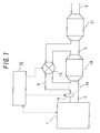
- FIG. 1 is a diagram showing a schematic structure of an internal combustion engine according to the present embodiment, and an exhaust system and a control system thereof.
- An internal combustion engine I shown in FIG. 1 is a diesel engine. Note that the interior of the internal combustion engine I and an intake system thereof are omitted in FIG. l.
- an exhaust pipe 5 is connected to the internal combustion engine 1 as an exhaust passage through which exhaust gas flows after being discharged from the internal combustion engine 1.
- the exhaust pipe 5 is connected downstream to a muffler (not shown).
- a storage-reduction type NOx catalyst (hereinafter, abbreviated as "NSR") 10 for purifying NOx contained in the exhaust gas is provided in the exhaust pipe 5.
- a filter 11 for trapping particulate matter contained in the exhaust gas is provided on the downstream side of the NSR 10 in the exhaust pipe 5.
- an oxidation catalyst CCo having an oxidation ability may be added to the NSR 10.
- a bypass pipe 6 serving as a bypass passage branches off from the exhaust pipe 5 in a bifurcating portion 5a upstream of the NSR 10.
- a switch valve 15 for switching to allow or block the flow of the exhaust gas from the internal combustion engine 1 into the bypass pipe 6 is provided in the bypass pipe 6.
- the bypass pipe 6 merges into the exhaust pipe 5 at a position between the NSR 10 and the filter 11.
- the switch valve 15 By operating the switch valve 15 to cause the exhaust gas from the internal combustion engine 1 to pass directly through the exhaust pipe 5, the exhaust gas is enabled to pass through both the NSR 10 and the filter 11. Similarly, by allowing the exhaust gas from the internal combustion engine 1 to pass through the bypass pipe 6, the exhaust gas is enabled to bypass the NSR 10 and to pass only through the filter 11.
- a fuel addition valve 14 for adding fuel serving as a reducer to the exhaust gas during a NOx reduction treatment or a SOx poisoning regeneration treatment of the NSR 10, and during a PM regeneration treatment of the filter 11 is provided on the upstream side of the NSR 10 in the exhaust pipe 5.
- the NSR 10 described above functions as an exhaust purification device in the present embodiment.
- the fuel addition valve 14 functions as reducer supply means.
- An electronic control unit (ECU) 20 for controlling the internal combustion engine 1 and the exhaust system thereof is also provided for the internal combustion engine 1 and the exhaust system which are structured as described above.
- the ECU 20 is a unit for not only controlling the operational state of the internal combustion engine 1 and the like according to the operating conditions of the internal combustion engine 1 and requests from a driver, but also performing control relating to an exhaust purification system including the NSR 10 and the filter 11 for the internal combustion engine 1.
- Sensors relating to control of the operational state of the internal combustion engine 1, such as an airflow meter, a crank position sensor, and an accelerator position sensor, which are not shown in the drawing, are connected to the ECU 20 via electric wirings, and output signals from these sensors are applied to the ECU 20.
- a fuel injection valve (not shown) and the like in the internal combustion engine 1 are connected to the ECU 20 via electric wiring, while the switch valve 15, the fuel addition valve 14, and the like of the present embodiment are connected to the ECU 20 via electric wiring so that these valves and the like are controlled by the ECU 20.
- the ECU 20 includes a CPU, a ROM, a RAM, and the like. Programs for executing various controls relating to the internal combustion engine 1 and maps storing data are stored in the ROM. An addition-synchronous bypass control execution determination routine according to the present embodiment, which will be described below, is one of the programs stored in the ROM in the ECU 20.
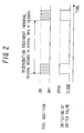
- FIG. 2 is a timing chart relating to fuel addition from the fuel addition valve 14 and switching of the switch valve 15 in the NOx reduction treatment.
- the addition-synchronous bypass control functions as regeneration exhaust flow rate control
- the ECU 20 for executing the addition-synchronous bypass control and the switch valve 15 function as regeneration exhaust flow rate control means.
- the ECU 20 also functions as regeneration means in the present embodiment.
- the interval of the NOx reduction treatment may significantly vary depending on the amount of NOx stored in the NSR 10 and the amount of NOx discharged from the internal combustion engine 1.
- the magnitude relation between a decrease in the amount of discharged NOx due to improvement in the rate of purification by the NSR 10 and an increase in the amount of discharged NOx from the bypass pipe 6 may change.
- the above amounts of discharged NOx may be compared in advance by adjustment in a steady state. In this method, however, it is sometimes difficult to adapt to a change in interval in an actual transient state.
- a decrease in the amount of discharged NOx due to improvement in the rate of purification by the NSR 10 and an increase in the amount of discharged NOx from the bypass pipe 6 are compared with each other regarding an interval of the NOx reduction treatment.
- the addition-synchronous bypass control is executed only when it is determined that the decrease in the amount of discharged NOx due to improvement in the rate of purification by the NSR 10 is larger than the increase in the amount of discharged NOx from the bypass pipe 6.
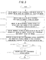
- FIG. 3 shows a flowchart of the addition-synchronous bypass control execution determination routine of the present embodiment.
- This routine is a program stored in the ROM in the ECU 20, and is a routine which is executed every predetermined period by the ECU 20 during execution of the NOx reduction treatment.
- the amount of NOx (g/s) discharged from the internal combustion engine 1 per unit time is derived from a current engine speed and a current fuel injection amount. More specifically, the amount of NOx (g/s) discharged from the internal combustion engine I per unit time is derived by reading the amount of NOx discharged per unit time, which corresponds to the current engine speed and the current fuel injection amount, from a map storing the relation between the engine speed and the fuel injection amount and the amount of NOx discharged from the internal combustion engine 1 per unit time.
- the routine proceeds to S 102 after the process of S 101 is completed.
- the flow division ratio of the exhaust gas into the bypass pipe 6, which is controlled by the switch valve 15, is derived based on a current intake air amount. More specifically, the flow division ratio of the exhaust gas into the bypass pipe 6 is derived by reading the value of the flow division ratio corresponding to the current intake air amount from a map storing the relation between the intake air amount and a control target value of the flow division ratio in the addition-synchronous bypass control. The routine proceeds to S 103 after the process of S 102 is completed.
- an increase in the amount of NOx discharged through the bypass pipe 6 while the switch valve 15 is open is calculated. More specifically, the increase in the amount of NOx is calculated by multiplying the amount of NOx (g/s) discharged from the internal combustion engine 1 per unit time which has been derived in S 101, by the valve open time (s) of the switch valve 15, and the flow division ratio derived in S102. The routine proceeds to S104 after the process of S103 is completed.
- an increase in the rate of purification of NOx by the addition-synchronous bypass control is derived from a current bed temperature of the NSR 10 and the current intake air amount. More specifically, the increase in the rate of purification of NOx is derived by reading the value of the increase in the rate of purification of NOx, which corresponds to the current bed temperature of the NSR 10 and the current intake air amount, from a map storing the relation between the bed temperature of the NSR 10 and the intake air amount and the increase in the rate of purification of NOx.
- the routine proceeds to S 105 after the process of S 104 is completed.
- a decrease in the amount of NOx discharged from the NSR 10 by the addition-synchronous bypass control is calculated. More specifically, the decrease in NOx discharged from the NSR 10 is calculated by multiplying a NOx reduction interval (s), by the amount of NOx (g/s) discharged from the internal combustion engine 1 per unit time and the increase in the rate of purification of NOx due to the decreased SV.
- the routine proceeds to S 106 after the process of S105 is completed.
- the amount of NOx discharged through the bypass pipe 6 while the switch valve 15 is open is compared with the decrease in the amount of NOx discharged from the NSR 10 by the addition-synchronous bypass control, which has been calculated in S105. If it is determined that the decrease in the amount of discharged NOx by the addition-synchronous bypass control is larger than the amount of NOx discharged through the bypass pipe 6 while the switch valve 15 is open, the routine proceeds to S107. On the other hand, the routine is terminated once if it is determined that the amount of NOx discharged through the bypass pipe 6 while the switch valve 15 is open is equal to or larger than the decrease in the amount of discharged NOx by the addition-synchronous bypass control.
- the amount of NOx discharged through the bypass pipe 6 while the switch valve 15 is open (which can also be referred to as the "increase in the amount of discharged NOx") is compared with the decrease in the amount of NOx discharged from the NSR 10 by the addition-synchronous bypass control, which has been calculated in S105.
- the addition-synchronous bypass control is executed only when the decrease in the amount of NOx discharged from the NSR 10 by the addition-synchronous bypass control is larger. Accordingly, the addition-synchronous bypass control can be executed only when it is determined that the total emission is improved by performing the addition-synchronous bypass control. The effect of improving emission can therefore be reliably obtained.
- the ECU 20 for performing the processes of S 101 through S106 functions as purification substance amount determining means in the present embodiment.
- the exhaust purification device may be a DPNR in which a storage-reduction type NOx catalyst is carried by a filter, or a selective-reduction type NOx catalyst.
- the present invention may be applied to PM regeneration of the DPNR.
- the present invention may also be applicable to an exhaust purification system using a liquid other than fuel, for example, a urea solution, as a reducer.
- a method for supplying fuel to the exhaust purification device is not limited to addition of the fuel from the fuel addition valve 14, but may be implemented by, for example, auxiliary injection in the internal combustion engine 1.
- the addition-synchronous bypass control is executed by switching the switch valve 15 between an open state and a closed state.
- the degree of opening of the switch valve 15 may be continuously varied to appropriately adjust the amount of exhaust gas passing through the bypass pipe 6 and the amount of exhaust gas passing through the NSR 10, of the exhaust gas passing through the exhaust pipe 5.
- the addition-synchronous bypass control may be executed by using a three-way valve provided in the bifurcating portion 5a.
- the amount of NOx discharged through the bypass pipe 6 while the switch valve 15 is open and the decrease in the amount of discharged NOx due to improvement in the rate of purification by the NSR 10 are compared with each other for the regeneration treatment (NOx reduction) interval.
- the period for comparison is not limited to the NOx reduction interval.
- the rate of purification by the NSR 10 gradually decreases as NOx is stored in the NSR 10. Therefore, comparison may be performed for a period in which significant decrease in the amount of discharged NOx due to improvement in the rate of purification by the NSR 10 is actually expected.
- a mean value of the amounts of NOx discharged through the bypass pipe 6 while the switch valve 15 is open may be compared with a mean value of the decreases in the amount of discharged NOx due to improvement in the rate of purification by the NSR 10.
- the method for calculating the amount of NOx discharged through the bypass pipe 6 while the switch valve 15 is open and the decrease in the amount of NOx discharged from the NSR 10 by the addition-synchronous bypass control is not specifically limited to the method described in the present embodiment.
- the above calculation method may be modified as appropriate if there is any method capable of calculating these values more accurately.
- the amount of NOx discharged through the bypass pipe 6 while the switch valve 15 is open is compared with the decrease in the amount of NOx discharged from the NSR 10 by the addition-synchronous bypass control, which has been calculated in S105.
- the addition-synchronous bypass control is executed only when it is determined that the decrease in the amount of NOx discharged from the NSR 10 by the addition-synchronous bypass control is larger than the amount of NOx discharged through the bypass pipe 6 while the switch valve 15 is open.
- the method for determining whether the addition-synchronous bypass control is executed or not based on the amount of NOx discharged through the bypass pipe 6 while the switch valve 15 is open and the decrease in the amount of NOx discharged from the NSR 10 by the addition-synchronous bypass control is not limited to this.
- the above method for determining whether the addition-synchronous bypass control is executed or not may be modified as appropriate by, for example, multiplying one of the above two values by a weighting coefficient.
- the addition-synchronous bypass control may be executed when it is determined that the total emission is substantially improved in view of the following two factors: the amount of NOx discharged through the bypass pipe 6 while the switch valve 15 is open; and the decrease in the amount of NOx discharged from the NSR 10 by the addition-synchronous bypass control.
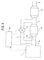
- FIG. 4 shows a schematic structure of an internal combustion engine according to the present embodiment, and an exhaust system and a control system thereof.
- a fuel addition valve 24 is provided in an exhaust pipe 5 on the downstream side of a bifurcating portion 5a to a bypass pipe 6 in the exhaust pipe 5.
- An oxidation catalyst 21 is also provided on the downstream side of a merging portion at which the bypass pipe 6 merges with the exhaust pipe 5, and that is located on the downstream side of an NSR 10 in the exhaust pipe 5.
- the structure is otherwise the same as that shown in FIG. 1 . Therefore, in the following description, the same components as those shown in FIG. 1 will be denoted by the same reference numerals and characters, and description thereof will be omitted.
- a NOx reduction treatment is performed according to the timing chart of FIG. 2 .
- NH 3 discharged from the NSR 10 may be oxidized back to NOx in the oxidation catalyst 21.
- NOx thus generated may be discharged from the oxidation catalyst 21, which may reduce the rate of purification of NOx as a result.
- a decrease in the amount of discharged NOx due to improvement in the rate of purification by the NSR 10 and the sum of an increase in the amount of NOx discharged from the bypass pipe 6 and an increase in the amount of NOx through oxidation of NH 3 discharged from the NSR 10 by the oxidation catalyst 21 are compared with each other for an interval of the NOx reduction treatment.
- the addition-synchronous bypass control is executed only when it is determined that the decrease in the amount of discharged NOx due to improvement in the rate of purification by the NSR 10 is larger than the sum of the increase in the amount of NOx discharged from the bypass pipe 6 and the increase in the amount of NOx through oxidation of NH 3 discharged from the NSR 10 by the oxidation catalyst 21.
- FIG. 5 is a flowchart showing an addition-synchronous bypass control execution determination routine 2 of the present embodiment.
- This routine is a program stored in the ROM in the ECU 20, and is a routine which is executed every predetermined period by the ECU 20 while the NOx reduction treatment is performed. Since the processes of S 101 to S 105 in this routine are the same as those of the addition-synchronous bypass control execution determination routine shown in FIG. 3 , description thereof will be omitted.
- the amount of NH 3 discharged from the NSR 10 in a NOx reduction (regeneration treatment) interval shown in FIG. 2 is derived from the sum of the amount of NOx discharged from the internal combustion engine 1 in the NOx reduction interval and the amount of NOx stored in the NSR 10, and an estimated value of an air-fuel ratio in the addition-synchronous bypass control.
- the total amount of NOx is derived from a product of the amount of NOx (g/s) discharged from the internal combustion engine 1 per unit time which is derived in S 101 and the time of the NOx reduction interval, and the amount of NOx stored in the NSR 10 which is estimated from the history of the operational state of the internal combustion engine 1.
- the amount of NH 3 discharged from the NSR 10 in the NOx reduction interval is derived by reading the amount of NH 3 corresponding to the current total amount of NOx and the estimated air-fuel ratio, from a map storing the relation among the total amount of NOx, the air-fuel ratio estimated based on the amount of fuel added from the fuel addition valve 24 to the exhaust gas and the intake air amount, and the amount of NH 3 discharged from the NSR 10 in the NOx reduction interval. Note that, at this time, a part of the amount of NOx discharged from the internal combustion engine 1 in the NOx reduction (regeneration treatment) interval passes through the bypass pipe 6 and is not introduced into the NSR 10. This value is ignored as an error in the present embodiment. The routine proceeds to S202 after the process of S201 is completed.
- the conversion ratio of NH 3 discharged from the NSR 10 into NOx in the oxidation catalyst 21 is derived from the bed temperature of the oxidation catalyst 21. More specifically, the conversion ratio is derived by reading the value of the conversion ratio corresponding to a current bed temperature of the oxidation catalyst 21 from a map storing the relation between the bed temperature of the oxidation catalyst 21 and the conversion ratio. Note that the bed temperature of the oxidation catalyst 21 may be obtained by detecting the temperature of the exhaust gas discharged from the oxidation catalyst by an exhaust temperature sensor (not-shown). The bed temperature of the oxidation catalyst 21 may alternatively be estimated from the operational state of the internal combustion engine 1. The routine proceeds to S203 after the process of S202 is completed.
- the amount of NOx generated through oxidation of NH 3 discharged from the NSR 10 by the oxidation catalyst 21 is calculated. More specifically, the amount of NOx generated through oxidation of NH 3 discharged from the NSR 10 in the NOx reduction interval by the oxidation catalyst 21 is calculated by multiplying the amount of NH 3 discharged from the NSR 10 in the NOx reduction interval, which has been derived in S201, by the conversion ratio into the NOx derived in S202.
- the routine proceeds to S204 after the process of S203 is completed.
- the routine proceeds to S 107 if it is determined that the decrease in the amount of NOx discharged from the NSR 10 by the addition-synchronous bypass control is larger than the sum of the amount of NOx discharged through the bypass pipe 6 while the switch valve 15 is open and the amount of NOx generated through oxidation of NH 3 discharged from the NSR 10 in the NOx reduction interval by the oxidation catalyst 21.
- the routine is terminated once if it is determined that the total amount of NOx is equal to or larger than the decrease in the amount of NOx discharged from the NSR 10 by the addition-synchronous bypass control.
- the sum of the amount of NOx discharged through the bypass pipe 6 while the switch valve 15 is open and the amount of NOx generated through oxidation of NH 3 discharged from the NSR 10 in the NOx reduction interval by the oxidation catalyst 21 which has been calculated in S203 is compared with the decrease in the amount of NOx discharged from the NSR 10 by the addition-synchronous bypass control.
- the addition-synchronous bypass control is executed only when the decrease in the amount of NOx discharged from the NSR 10 by the addition-synchronous bypass control is larger than the total amount of NOx. Accordingly, the addition-synchronous bypass control can be executed only when it is determined that the total emission is improved by executing the addition-synchronous bypass control. Therefore, the effect of improving emission can be more reliably obtained.
- the ECU 20 for performing the processes of S 101 through S204 functions as NOx amount determining means in the present embodiment.
- the sum of the amount of NOx discharged through the bypass pipe 6 while the switch valve 15 is open and the amount of NOx generated through oxidation of NH 3 discharged from the NSR 10 in the NOx reduction interval by the oxidation catalyst 21 is compared with the decrease in the amount of discharged NOx due to improvement in the rate of purification by the NSR 10 for the NOx reduction interval.
- the period for comparison is not limited to the NOx reduction interval.
- a mean value of the sums of the amount of NOx discharged through the bypass pipe 6 while the switch valve 15 is open and the amount of NOx generated through oxidation of NH 3 discharged from the NSR 10 in the NOx reduction interval by the oxidation catalyst 21 may be compared with a mean value of the decreases in the amount of discharged NOx due to improvement in the rate of purification by the NSR 10.
- the method for calculating the amount of NOx generated through oxidation of NH 3 discharged from the NSR 10 in the NOx reduction interval by the oxidation catalyst 21 is not specifically limited to the method described in the present embodiment.
- the above calculation method may be modified as appropriate if there is any method capable of calculating the value more accurately.
- the sum of the amount of discharged NOx calculated in S 103 and the amount of generated NOx calculated in S203 is compared with the decrease in the amount of discharged NOx calculated in S105.
- the addition-synchronous bypass control is executed only when it is determined that the decrease in the amount of discharged NOx calculated in S105 is larger than the sum of the amount of discharged NOx calculated in S 103 and the amount of generated NOx calculated in S203.
- the method for determining whether the addition-synchronous bypass control is executed or not based on the amount of NOx discharged through the bypass pipe 6 while the switch valve 15 is open, the decrease in the amount of NOx discharged from the NSR 10 by the addition-synchronous bypass control, and the amount of NOx generated through oxidation of NH 3 discharged from the NSR 10 by the oxidation catalyst 21 is not limited to this.
- the above method for determining whether the addition-synchronous bypass control is executed or not may be modified as appropriate by, for example, multiplying any of the above three values by a weighting coefficient.
- the addition-synchronous bypass control may be executed when it is determined that the total emission is substantially improved in view of the following three factors: the amount of NOx discharged through the bypass pipe 6 while the switch valve 15 is open; the amount of NOx generated through oxidation of NH 3 discharged from the NSR 10 by the oxidation catalyst 21; and the decrease in the amount of NOx discharged from the NSR 10 by the addition-synchronous bypass control.
- a reducer is supplied to the exhaust purification device and a part of the exhaust gas is caused to bypass the exhaust purification device, whereby exhaust emission can be more reliably improved.
Landscapes
- Engineering & Computer Science (AREA)
- Chemical & Material Sciences (AREA)
- Combustion & Propulsion (AREA)
- Mechanical Engineering (AREA)
- General Engineering & Computer Science (AREA)
- Chemical Kinetics & Catalysis (AREA)
- Health & Medical Sciences (AREA)
- Biomedical Technology (AREA)
- Environmental & Geological Engineering (AREA)
- Analytical Chemistry (AREA)
- General Chemical & Material Sciences (AREA)
- Oil, Petroleum & Natural Gas (AREA)
- Exhaust Gas After Treatment (AREA)
- Exhaust Gas Treatment By Means Of Catalyst (AREA)
Applications Claiming Priority (3)
| Application Number | Priority Date | Filing Date | Title |
|---|---|---|---|
| JP2007009813 | 2007-01-19 | ||
| JP2007322119A JP2008196478A (ja) | 2007-01-19 | 2007-12-13 | 内燃機関の排気浄化システム |
| PCT/JP2008/051136 WO2008088090A1 (ja) | 2007-01-19 | 2008-01-21 | 内燃機関の排気浄化システム |
Publications (2)
| Publication Number | Publication Date |
|---|---|
| EP2128397A1 true EP2128397A1 (de) | 2009-12-02 |
| EP2128397A4 EP2128397A4 (de) | 2010-11-24 |
Family
ID=39636078
Family Applications (1)
| Application Number | Title | Priority Date | Filing Date |
|---|---|---|---|
| EP08703948A Withdrawn EP2128397A4 (de) | 2007-01-19 | 2008-01-21 | Abgasreinigungssystem für einen verbrennungsmotor |
Country Status (4)
| Country | Link |
|---|---|
| US (1) | US20100077736A1 (de) |
| EP (1) | EP2128397A4 (de) |
| JP (1) | JP2008196478A (de) |
| WO (1) | WO2008088090A1 (de) |
Families Citing this family (3)
| Publication number | Priority date | Publication date | Assignee | Title |
|---|---|---|---|---|
| US9016046B2 (en) * | 2012-01-02 | 2015-04-28 | Ford Global Technologies, Llc | Internal combustion engine with exhaust-gas aftertreatment arrangement and method for operating an internal combustion engine of said type |
| US10874496B2 (en) | 2014-06-25 | 2020-12-29 | Canary Medical Inc. | Devices, systems and methods for using and monitoring implants |
| EP4198272B1 (de) * | 2021-12-20 | 2024-11-20 | Volvo Truck Corporation | Verfahren zur steuerung des betriebs eines abgasnachbehandlungssystems |
Family Cites Families (11)
| Publication number | Priority date | Publication date | Assignee | Title |
|---|---|---|---|---|
| JP2830464B2 (ja) * | 1989-12-06 | 1998-12-02 | トヨタ自動車株式会社 | 内燃機関の排気浄化装置 |
| JP3228232B2 (ja) * | 1998-07-28 | 2001-11-12 | トヨタ自動車株式会社 | 内燃機関の排気浄化装置 |
| JP3757668B2 (ja) | 1999-03-18 | 2006-03-22 | 日産自動車株式会社 | エンジンの排気浄化装置 |
| JP3628277B2 (ja) | 2001-05-25 | 2005-03-09 | 日野自動車株式会社 | エンジンの排ガス浄化装置 |
| JP3945335B2 (ja) * | 2002-07-31 | 2007-07-18 | トヨタ自動車株式会社 | 内燃機関の排気浄化装置 |
| CA2422188A1 (en) * | 2002-10-02 | 2004-04-02 | Westport Research Inc. | Bypass controlled regeneration of nox adsorbers |
| CA2406386C (en) * | 2002-10-02 | 2004-05-18 | Westport Research Inc. | Method and apparatus for regenerating nox adsorbers |
| CA2453689A1 (en) * | 2003-03-14 | 2004-09-14 | Westport Research Inc. | Management of thermal fluctuations in lean nox adsorber aftertreatment systems |
| US7900441B2 (en) * | 2004-02-12 | 2011-03-08 | Fleetguard, Inc. | Precat-NOx adsorber exhaust aftertreatment system for internal combustion engines |
| GB0421168D0 (en) * | 2004-09-23 | 2004-10-27 | Ford Global Tech Llc | An emission control system for an engine |
| JP2006233894A (ja) * | 2005-02-25 | 2006-09-07 | Toyota Motor Corp | 内燃機関の排気浄化装置 |
-
2007
- 2007-12-13 JP JP2007322119A patent/JP2008196478A/ja active Pending
-
2008
- 2008-01-21 EP EP08703948A patent/EP2128397A4/de not_active Withdrawn
- 2008-01-21 US US12/448,947 patent/US20100077736A1/en not_active Abandoned
- 2008-01-21 WO PCT/JP2008/051136 patent/WO2008088090A1/ja not_active Ceased
Also Published As
| Publication number | Publication date |
|---|---|
| US20100077736A1 (en) | 2010-04-01 |
| JP2008196478A (ja) | 2008-08-28 |
| EP2128397A4 (de) | 2010-11-24 |
| WO2008088090A1 (ja) | 2008-07-24 |
Similar Documents
| Publication | Publication Date | Title |
|---|---|---|
| EP2146065B1 (de) | Abgasreinigungssystem für einen verbrennungsmotor | |
| US8720190B2 (en) | Method for predicting SOx stored at DeNOx catalyst and exhaust system using the same | |
| US8978367B2 (en) | Exhaust gas purifying system of internal combustion engine | |
| EP2824296A1 (de) | Abgasreinigungsvorrichtung für einen verbrennungsmotor | |
| CN101490375A (zh) | 内燃机排气净化系统 | |
| EP2868881A1 (de) | Abgasreinigungsvorrichtung für einen verbrennungsmotor | |
| US9644513B2 (en) | Method of regenerating lean NOx trap of exhaust purification system provided with lean NOx trap and selective catalytic reduction catalyst and exhaust purification system | |
| EP3133258B1 (de) | Steuerungssystem für einen verbrennungsmotor und steuerungsverfahren | |
| EP2873823A1 (de) | Abgasreinigungssystem für einen Verbrennungsmotor | |
| JP2010053703A (ja) | 排気浄化装置 | |
| US8347608B2 (en) | Exhaust gas purification system for an internal combustion engine | |
| CN107448264A (zh) | 内燃机的排气净化装置 | |
| CN101583781A (zh) | 内燃机的排气净化系统 | |
| EP2128397A1 (de) | Abgasreinigungssystem für einen verbrennungsmotor | |
| EP1510679B1 (de) | Verfahren und Vorrichtung zur Schwefelentfernung eines Abgaskatalysators | |
| EP2264291B1 (de) | Abgasreinigungssystem für verbrennungsmotor | |
| US7963102B2 (en) | Exhaust purification system for internal combustion engine | |
| KR20150017382A (ko) | 촉매 미립자 필터를 포함하는 배기 가스 처리 시스템 및 배기 가스 처리 방법 | |
| EP3130774B1 (de) | Abgasreinigungssystem für einen verbrennungsmotor | |
| JP4729990B2 (ja) | 内燃機関の排気浄化装置 | |
| JP2008025467A (ja) | 内燃機関の排気浄化システム | |
| JP4327759B2 (ja) | 内燃機関の排気浄化システムおよび添加還元剤量決定方法 | |
| JP2008280980A (ja) | 内燃機関の排気浄化システム | |
| JP4720748B2 (ja) | 内燃機関の排気浄化システム | |
| JP2007032396A (ja) | 内燃機関の排気浄化装置 |
Legal Events
| Date | Code | Title | Description |
|---|---|---|---|
| PUAI | Public reference made under article 153(3) epc to a published international application that has entered the european phase |
Free format text: ORIGINAL CODE: 0009012 |
|
| 17P | Request for examination filed |
Effective date: 20090819 |
|
| AK | Designated contracting states |
Kind code of ref document: A1 Designated state(s): AT BE BG CH CY CZ DE DK EE ES FI FR GB GR HR HU IE IS IT LI LT LU LV MC MT NL NO PL PT RO SE SI SK TR |
|
| DAX | Request for extension of the european patent (deleted) | ||
| A4 | Supplementary search report drawn up and despatched |
Effective date: 20101026 |
|
| RIC1 | Information provided on ipc code assigned before grant |
Ipc: F01N 9/00 20060101ALI20101020BHEP Ipc: B01D 53/94 20060101ALI20101020BHEP Ipc: F01N 3/025 20060101ALI20101020BHEP Ipc: F01N 3/02 20060101ALI20101020BHEP Ipc: F01N 3/08 20060101AFI20101020BHEP Ipc: F01N 3/24 20060101ALI20101020BHEP Ipc: F01N 3/28 20060101ALI20101020BHEP Ipc: F01N 3/36 20060101ALI20101020BHEP |
|
| STAA | Information on the status of an ep patent application or granted ep patent |
Free format text: STATUS: THE APPLICATION IS DEEMED TO BE WITHDRAWN |
|
| 18D | Application deemed to be withdrawn |
Effective date: 20110526 |