EP2873324A2 - Dispositif de remplissage d'enveloppes en forme de tuyau - Google Patents
Dispositif de remplissage d'enveloppes en forme de tuyau Download PDFInfo
- Publication number
- EP2873324A2 EP2873324A2 EP20140190850 EP14190850A EP2873324A2 EP 2873324 A2 EP2873324 A2 EP 2873324A2 EP 20140190850 EP20140190850 EP 20140190850 EP 14190850 A EP14190850 A EP 14190850A EP 2873324 A2 EP2873324 A2 EP 2873324A2
- Authority
- EP
- European Patent Office
- Prior art keywords
- filling tube
- filling
- receiving part
- tube
- intestinal
- Prior art date
- Legal status (The legal status is an assumption and is not a legal conclusion. Google has not performed a legal analysis and makes no representation as to the accuracy of the status listed.)
- Granted
Links
- 230000000968 intestinal effect Effects 0.000 claims abstract description 50
- 235000013580 sausages Nutrition 0.000 claims abstract description 21
- 235000011837 pasties Nutrition 0.000 claims abstract description 20
- 235000013372 meat Nutrition 0.000 claims abstract description 14
- 238000004804 winding Methods 0.000 claims description 4
- 235000019690 meat sausages Nutrition 0.000 claims 1
- 238000005429 filling process Methods 0.000 description 12
- 230000033001 locomotion Effects 0.000 description 11
- 238000000034 method Methods 0.000 description 5
- 210000001035 gastrointestinal tract Anatomy 0.000 description 4
- 239000007787 solid Substances 0.000 description 4
- 210000000936 intestine Anatomy 0.000 description 3
- 238000004519 manufacturing process Methods 0.000 description 3
- 238000005452 bending Methods 0.000 description 2
- 230000008878 coupling Effects 0.000 description 2
- 238000010168 coupling process Methods 0.000 description 2
- 238000005859 coupling reaction Methods 0.000 description 2
- 102000008186 Collagen Human genes 0.000 description 1
- 108010035532 Collagen Proteins 0.000 description 1
- 241000287828 Gallus gallus Species 0.000 description 1
- 230000006978 adaptation Effects 0.000 description 1
- 230000000712 assembly Effects 0.000 description 1
- 238000000429 assembly Methods 0.000 description 1
- 239000011324 bead Substances 0.000 description 1
- 230000015572 biosynthetic process Effects 0.000 description 1
- 229920001436 collagen Polymers 0.000 description 1
- 230000007423 decrease Effects 0.000 description 1
- 238000011161 development Methods 0.000 description 1
- 230000018109 developmental process Effects 0.000 description 1
- 238000006073 displacement reaction Methods 0.000 description 1
- 238000009826 distribution Methods 0.000 description 1
- 238000001125 extrusion Methods 0.000 description 1
- 239000000945 filler Substances 0.000 description 1
- 238000007667 floating Methods 0.000 description 1
- 238000004806 packaging method and process Methods 0.000 description 1
- 230000002028 premature Effects 0.000 description 1
- 230000000750 progressive effect Effects 0.000 description 1
- 238000007665 sagging Methods 0.000 description 1
- 238000010008 shearing Methods 0.000 description 1
- 238000003860 storage Methods 0.000 description 1
- 238000009827 uniform distribution Methods 0.000 description 1
- 238000011144 upstream manufacturing Methods 0.000 description 1
Images
Classifications
-
- A—HUMAN NECESSITIES
- A22—BUTCHERING; MEAT TREATMENT; PROCESSING POULTRY OR FISH
- A22C—PROCESSING MEAT, POULTRY, OR FISH
- A22C11/00—Sausage making ; Apparatus for handling or conveying sausage products during manufacture
- A22C11/02—Sausage filling or stuffing machines
-
- A—HUMAN NECESSITIES
- A22—BUTCHERING; MEAT TREATMENT; PROCESSING POULTRY OR FISH
- A22C—PROCESSING MEAT, POULTRY, OR FISH
- A22C11/00—Sausage making ; Apparatus for handling or conveying sausage products during manufacture
- A22C11/02—Sausage filling or stuffing machines
- A22C11/0209—Stuffing horn assembly
- A22C11/0218—Stuffing horn assembly with multiple interchangeable stuffing horns, e.g. magazine arrangements
-
- A—HUMAN NECESSITIES
- A22—BUTCHERING; MEAT TREATMENT; PROCESSING POULTRY OR FISH
- A22C—PROCESSING MEAT, POULTRY, OR FISH
- A22C11/00—Sausage making ; Apparatus for handling or conveying sausage products during manufacture
- A22C11/02—Sausage filling or stuffing machines
- A22C11/0245—Controlling devices
- A22C11/0263—Braking means
Definitions
- the present invention relates to a device for filling tubular casings, with a pasty mass, in particular of intestinal caterpillars with sausage meat, with at least one about its longitudinal axis rotatable and drivable filling tube on which a fillable with a mass shell can be pulled up, wherein the filling tube to one end rotatably mounted on a receiving part and the opposite, open end is associated with a pulled over the filling tube shell operatively engageable intestinal brake unit.
- the invention further relates to a filling machine for producing sausages of pasty mass, in particular from sausage meat.
- Devices for filling tubular casings are used in particular on filling machines for the production of sausage strands, by means of which a pasty mass, such as sausage meat or the like, in portions or in the form of portions of predetermined amount in tubular shells made of plastic or natural casing is filled.
- a pasty mass such as sausage meat or the like
- the filled casing is divided or turned off at predetermined intervals between the individual filling steps, as a result of which separable strand sections of the same length and the same weight are generated which can subsequently be separated from one another.
- separable strand sections of the same length and the same weight are generated which can subsequently be separated from one another.
- the tubular casing Before filling the tubular casing, this is mounted on the filling tube of a filling device, wherein the tubular casing whose actual length corresponds to a multiple of the length of the filling tube, is already usually gathered, so that the shirred casing, also referred to as intestinal caterpillar, is shorter than the filling tube.
- the shirred casings can have different diameters, also called calibers.
- the filling process is briefly interrupted and, in order to separate the input portion from the subsequent portion, the shell portion located on the filling tube rotated by means of the filling tube rotatably mounted about its longitudinal axis.
- the filling tube is connected for this purpose with a arranged on the receiving part for the filling tube drive.
- the filling tube, together with the drawn on the filling tube, shirred casing section is rotated about its longitudinal axis and thus produced after a given in the tubular shell amount of sausage meat a constricting or twisting.
- the intestinal brake unit has in this regard a rotatably mounted brake ring, which is to ensure a frictional or positive connection between the outer lateral surface of the filling tube and a portion of the intestinal caterpillar mounted thereon and thus transmits the rotary motion generated by the filling tube to the over-pulled shell portion.
- the drawn on the filling tube tubular Shell used up and it must be a new, shirred tubular casing mounted on the filling tube.
- the intestinal brake unit is to be removed from the open end of the filling tube, in which the intestinal brake unit is withdrawn from the same in the longitudinal direction of the filling tube.
- a new, shirred tubular casing is slid or drawn onto the filling tube from the open end of the filling tube with the aid of, for example, a gut gripping device, and then the intestinal catching device or intestinal brake unit is brought back into contact with the front open end of the filling tube, whereby the tubular casing at least in Area of Artrohrspitze is pressed onto the filling tube.
- a filling device of the aforementioned type is known, on the filling tube at regular intervals tubular sheaths are raised or pushed.
- filling tubes are used, which have large length dimensions (minimum lengths) to accommodate correspondingly long tubular sheath sections can.
- minimum lengths minimum lengths
- a predetermined minimum number of mutually separated strand sections can be generated without shell change.
- the bent filling tubes may vibrate, resulting in incorrect loading of the tubular casing.
- the filling tubes are bent when changing sheath so that they can not be used during further operation of the filling device and must be replaced.
- the object of the present invention is to improve a device for filling tubular casings of the aforementioned type in such a way that improved process reliability is ensured during the operation of the filling device.
- the invention solves the underlying object in a device for filling tubular envelopes of the aforementioned type by a support member disposed on the support means, which has a longitudinally of the filling tube at a distance from the receiving part arranged support member for the filling tube, wherein the support member for receiving on the Fill tube acting transverse forces is set up.
- the invention is based on the recognition, by means of the support means and its filler tube engaging on the support member, that spaced, i. is arranged at a distance to the receiving part and thus rotatably mounted on the receiving part end of the filling tube to form a second bearing point for the filling tube.
- the filling tube is additionally supported in a region between its rotatably mounted end and the open end, where the pasty mass exits, whereby transverse forces acting on the filling tube can be absorbed.
- the fill tube can be prevented from moving transversely to its longitudinal direction.
- the support device itself has a preferably rigid connection to the receiving part of the filling device.
- the support element preferably has a rotary receptacle for the filling tube, which ensures that the filling tube is rotatably received about its longitudinal axis on the support element.
- the rotary receptacle is preferably designed as a pivot bearing and takes directly on the outer diameter of the filling tube.
- the support element is movable along the filling tube. This ensures that the distance between the support member is variable to the receiving part, so that the sections of the filling tube can be supported by the support element targeted at which temporarily act the largest lateral forces.
- the support element is displaceable along the filling tube between two end positions. The first end position is close to the receiving part and thus near the Golfrohrende, which is rotatably and drivably disposed on the receiving part. The second end position is close to the open Grezierende.
- the term "close” is preferably to be understood as meaning a distance to a respective filling tube end of 1/5 or less, based on the total length of the filling tube.
- the support member is preferably controlled so that it is positioned in the second end position near the open filling tube of the, when the shirred casing is pushed onto the filling tube.
- the shearing forces possibly acting on the shirred casing, in particular at the open end, can thus be reliably absorbed by the support element which can be positioned there.
- the support element along the filling tube or in the longitudinal direction of the filling tube is slidably mounted.
- a preferred embodiment of the invention provides that at the open end of the filling tube, the positionable support member when pushing the shirred casing, also referred to as intestinal caterpillar, is automatically displaced in the direction of the rotatably mounted end of the filling tube, so that the distance between the support member and the receiving part reduced for the filling tube.
- a plurality of rotatable and drivable filling tubes are arranged on the receiving part, wherein each filling tube is mounted on a spaced apart from the receiving part and thus rotatably mounted end of the filling tube supporting member.
- a plurality of filling tubes an improved filling process with respect to the economy is achieved on the filling device designed according to the invention.
- the filling process of the shell mounted thereon can be implemented on the respective other filling tube.
- the filling device on the receiving part on two rotatably mounted filling tubes.
- each filling tube is preferably assigned a separate drive means.
- the second preferably designed as a floating bearing point for the filling tubes that none of the receiving part drivable mounted filling tubes when mounting a new tubular casing or when in contact with the Darmbremsaku is bent transversely to the longitudinal direction.
- the filling tubes stabilized with the support device are held, for example, positionally accurate to the intestinal gripping device or the intestinal brake unit, which simplifies the pushing on or pulling on of a new tubular casing and / or bringing the open end of a respective filling tube into contact with the casing brake unit.
- the inclusion of at least two bearing points of the filling tube also has the advantage that the filling tubes, even if they are slightly curved in the direction of extension, during the Abcardvorganges have a significantly reduced vibration behavior.
- the receiving part has a pivot plate which is movably held on the device and on which the filling tube preferably arranged horizontally projecting.
- the pivot plate has a plate plane on which the filling tube preferably projects vertically.
- the pivot plate has an axis of rotation, wherein the axis of rotation of the pivot plate and each axis of rotation of the filling tube are aligned parallel to each other.
- a structurally easy to implement pivotal movement of the filling tube is achieved at the filling device.
- an easily implementable rotary motion on the pivot plate to preferably its axis of rotation, a respective new filling tube to be loaded from its filling position to be moved.
- the filling position is the position of the filling tube at the filling device, in which the filling tube is brought into contact with the intestinal brake unit during the filling process, wherein the filling tube is transferred to a position in which a sufficient freedom of movement for the filling tube with the tubular shell stocking intestinal gripping device is available.
- the pivot plate preferably has a circular shape, whose central axis simultaneously forms the axis of rotation of the pivot plate.
- the preferably two or more filling tubes arranged on the pivoting plate are uniformly spaced and arranged symmetrically with respect to the axis of rotation of the pivoting plate, so that a uniform mass distribution of the filling tubes is provided on the pivoting plate.
- the filling tubes are also held during the pivotal movement of the pivot plate in its predetermined orientation to the axis of rotation, so that the pivoting movement can be performed at a high speed without the risk that the filling tubes are vibrated in such a way that permanent deformation of the filling tubes occur.
- the support element has a guide carriage, which along a parallel to the longitudinal axis of the filling tube aligned guideway of the support means is mobile.
- the support element can preferably be moved along the filling tube, whereby the distance of the support element to the end of the filling tube, which is rotatably and drivably held on the receiving part of the device, variable or is adjustable.
- the length of the receiving area on the filling tube for the ceremonischiebende on the filling tube or réelle istde tubular casing is made changeable and allows individual adaptation to, for example, different lengths tubular sheaths.
- the position of the support element is adapted to the filling tube depending on the length of the inflatable on the filling tube shell and / or changing during the filling length of the remaining remaining on the filling tube tubular casing.
- each guide track has two guide struts extending parallel to each other.
- the two mutually spaced guide struts which are designed as precision guide struts, an exact guidance of the guide carriage of the support element along the guideway of the support means and thus a positionally accurate alignment of the filling tube is ensured coaxially to the central axes.
- the use of two guide struts has the additional advantage that the guide carriage of the contactor part is preferably guided torsionally rigid along the guide path of the support device.
- the guide struts have a cylindrical cross section, but any other cross section, such as oval or rectangular is possible.
- the guide struts preferably extend almost over the entire length of the respective associated filling tube, whereby the support member can support almost every section of a respective filling tube.
- the support means preferably has a coaxial with the axis of rotation of the pivot plate arranged central strut on which the guide struts of a respective guideway are arranged to extend parallel.
- the guide struts of a respective guideway for each support element are aligned parallel to the central strut of the support means, whereby the movably received supporting elements precisely guided and an exact centering of the otherwise only one end rotatably and drivably received filling tubes is ensured.
- the ends of the guide struts are coupled on both sides via connecting flanges with the central strut, about what a solid and thus secure connection with the central strut and a positionally accurate alignment of the guide struts is ensured for the support elements to the central strut.
- connecting flanges further a structurally simple way for the formation of a solid, frame-like structure of the support device is ensured, which can thus absorb possible acting on these transverse forces, without the support itself bends or twisted disadvantageous.
- a partially along the central strut movable guide part of the intestinal brake unit is arranged.
- a coupling between the support means and the intestinal brake unit is created, whereby a preferred exact alignment of the intestinal brake unit is effected to the support means of the filling device according to the invention.
- the postponement of the intestinal brake unit on a supported by the support device filling tube can therefore be simplified and done safely.
- the guide member of the intestinal brake unit is preferably slidably movable along the free end of the central strut, whereby the distance between the Darmbremsaku and the filling tube can be changed so that then the change of the filling tubes by preferably pivoting of the receiving part of the filling device according to the invention is possible.
- the guide member remains in permanent contact with the free end of the central strut.
- Each supporting element preferably has a bearing part, via which a guttering ring is rotatably received, which is in each case rotationally fixedly received on the filling tube and slidingly movable along the filling tube.
- the tubular casing is pressed onto the outside of the filling tube, but also the open end of the tubular casing, also referred to as intestinal caterpillar, form-fitting or frictionally engaged with the Filling tube is brought into operative connection.
- the tubular sheath is preferably offset evenly over its entire length in a rotational movement, when the filling tube is rotated to produce the Abteil- or Abwindstellen by a predetermined angular extent. A twisting of the ends of the tubular casing to each other is thus prevented.
- the support element is adapted to be moved during the winding of the tubular casing on the filling tube, preferably by means of a gut gripping device in the direction of the receiving part.
- the support element is preferably arranged to be displaced during the filling of the tubular casing, by means of an intestinal slide in the direction of the open end of the filling tube.
- the distance between the support element and the receiving part is increased, in particular during the filling process of the tubular casing with the pasty mass, depending on the current length of the tubular casing on the filling tube and thus the Darmmit shakingring rotatably mounted on the support member in its position changed or adjusted along the filling tube.
- This ensures that the shirred tubular casing, also referred to as intestinal caterpillar, is brought to its original initial length only at the open end especially by the arranged at the top of the filling tube Darmbremsring.
- Moving the support element with his guide carriage along the guideway of the support means on the intestinal slide has the advantage that the support element does not require its own drive to be moved along the guide tube.
- a support device for at least one filling tube of a device for filling tubular casings with pasty mass, in particular of intestinal caterpillars with sausage meat which is characterized according to the invention by a support element for the filling tube, which in the longitudinal direction of the filling tube at a distance to a in the filling tube rotatably receiving part is arranged and adapted to receive forces acting on the filling tube forces, and wherein the support means is adapted for use on a device for filling tubular sheaths according to one of the preferred embodiments described above.
- a second bearing point is implemented for the particular filling pipe to be supported.
- the support member acting on the filling tube transversely to the longitudinal axis acting forces safely and further allows each open end of the filling tube positionally accurate to the shirred casing on the filling tube suspending intestinal gripping device or one with the shell at the open end of the filling tube align actively engageable intestinal brake unit.
- the support element along a parallel to the longitudinal axis of the filling tube extending guideway of the support means is movable, wherein the support means is preferably rigidly receivable on a formed as a swivel plate receiving part of a filling device.
- the invention also relates to a filling machine for producing sausages of pasty mass, in particular from sausage meat with a hopper for receiving the pasty mass with a feed pump for conveying the pasty mass and a device for filling tubular casings with a pasty mass, in particular of Cat broilers with sausage meat according to any one of claims 1-13, and preferably with at least one intestinal gripping device for shirred tubular casings, such as intestinal caterpillars or the like with two relatively movable holding gripping elements which are rotatably mounted on at least one lever element.
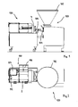
- the Figures 1 and 2 show a machine 100 for filling tubular casings, in particular of sausage casings, in conjunction with a header 110, on which a filling device 2 and a gut gripping device 112 is mounted.
- the machine 100 has a hopper 102 and an extrusion head 104, which is connected via an output tube 106 to a revolving magazine 4 of the filling device 2 in the medium-conducting manner.
- a drive unit 114 and a magazine 116 is arranged on the attachment 110, which is stored with a plurality of intestinal caterpillars.
- the intestinal gripping device 112, the drive unit 114 and the magazine 116 are basically rigidly connected to one another on the attachment via a frame structure, wherein the individual components preferably have mutually movably supporting assemblies or components.
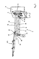
- the FIG. 3 shows the filling device 2 for filling tubular casings with a pasty mass of particular sausage meat.
- the revolver magazine 4 has a rotatably received receiving part 6 for two rotatably and drivably on the receiving part 6 arranged filling tubes 8, 10, on each of which can be filled with the pasty mass tubular casing can be pulled.
- the receiving part 6 is formed in particular as a pivot plate with a horizontally oriented to the axis of rotation.
- a support means 12 is arranged for the filling tubes, which for each filling tube 8, 10 at a distance x to the receiving part 6 and thus rotatably mounted end 14, 16 of the filling tube 8, 10 arranged support member 18, 20 has.
- the axis of rotation of the receiving part 6 designed as a swiveling plate and the axes of rotation of the filling tubes 8, 10 run parallel to one another and, moreover, the axes of rotation of the filling tubes 8, 10 are arranged uniformly spaced from the axis of rotation of the receiving part 6.
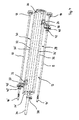
- FIG. 4 a detail view of the support means 12, which is intended to illustrate their structure and function.
- Each support element 18, 20 has a guide carriage 24, 26 which is in each case slide-along along a guide track 28, 30 of the support device 12 running parallel to the longitudinal axis of the filling tube 8, 10 so that the distance x of the support elements 18, 20 to the receiving part 6 is variable is.
- each guideway 28, 30 of two mutually parallel guide struts 32, 32 ' is formed.
- the support device 12 also has a coaxial with the axis of rotation of the receiving part 6 arranged central strut 34, to which the guide struts 32, 32 ' a respective guideway are arranged to extend parallel.
- the guide struts 32, 32 ' are coupled at the ends via a connecting flange 36, 36' to the central strut 34, so that the support device 12 forms a solid frame structure.
- FIG. 3 it can be seen, the free end of the central strut 34 of the support means 12 is coupled to a receptacle of a holding member 38 of the intestinal brake unit 22, whereby the support means 12 relative to their orientation transversely to the longitudinal axis of the central strut 34 is securely held to the pivot plate 6 of the filling device 2.
- the central strut 34 is displaceable in the receiving of the holding member 38 in the longitudinal direction.
- Each supporting element 18, 20 has a bearing part 40, 40 'configured as a rotary receptacle for a guttering ring 42, 42' held slidably along the filling tube, by means of which it is ensured that the end of the tubular casing pushed onto the filling tube during production of the dividing points between the individual sections of the strand sections to be produced is held in contact with the filling tube.
- a firm attachment of the tubular casing during the filling process at the open end 14 'of the filling tube 8 is effected via a brake ring, not shown, the intestinal brake unit 22.
- the support members 18, 20 are arranged, during the winding of the tubular casing on the respective filling tube 8, 10 by means of the intestinal gripping device 112 in the direction of rotatably and drivable attached to the receiving part 6 end 14, 16 of the filling tube 8, 10, whereby the distance x between support member 18, 20 and receiving part 6 is increased, and during the filling of the tubular casing, by means of a gutter slide, not shown in the direction of the open end 14 ', 16' of the filling tube 8, 10, whereby the distance x between support member 18, 20 and receiving part 6 is reduced to be moved.
- the pulling on of a tubular casing onto the filling tube 10 and the filling of a tubular casing accommodated on a filling tube 8 are carried out as explained below.
- the lower filling tube 8 is in the filling position for the wound on the filling tube, but not shown tubular casing.
- a casing brake unit 22 is brought into contact with the shell mounted on the stuffing tube and at the same time the open end of the tubular casing is brought into abutment with the guttering ring 42 so that the casing mounted on the stuffing tube 8 rotates the filling tube 8 around its axis of rotation produces the rotational movement generated uniformly over its entire length.
- the support member 20 is in its front end position in the vicinity of the open end 16 'of the filling tube 10, thereby ensuring that the filling tube 10 is aligned precisely to the intestinal gripping device 112 and the pulling over tubular casing.
- the support member 20 is then, since it has no own drive, moved by the intestinal gripping device 112 along the guide struts 32, 32 'in the direction of the formed as a pivot plate receiving part 6. After pulling the tubular casing through the intestinal gripping device this goes back to its original position.
- the gut brake unit 22 is pulled down from the open end 14 'of the filling tube 8 in the longitudinal direction of the filling tube, and then that formed as a pivot plate receiving part 6 pivoted by about 180 ° (arrow 44), so now more the previously upper and Now more stuffed with the tubular casing filling tube 10 is moved to the lower position and the empty filling tube 8 is then in the upper position.
- the pivotal movement of the pivot plate 6 can be made with the filling tubes about its axis of rotation at high speed, since a swinging of the filling tubes is counteracted by the support elements.
Landscapes
- Engineering & Computer Science (AREA)
- Life Sciences & Earth Sciences (AREA)
- Wood Science & Technology (AREA)
- Zoology (AREA)
- Food Science & Technology (AREA)
- Mechanical Engineering (AREA)
- Processing Of Meat And Fish (AREA)
Priority Applications (1)
| Application Number | Priority Date | Filing Date | Title |
|---|---|---|---|
| PL14190850T PL2873324T3 (pl) | 2013-11-13 | 2014-10-29 | Urządzenie do wypełniania rękawowych osłonek |
Applications Claiming Priority (1)
| Application Number | Priority Date | Filing Date | Title |
|---|---|---|---|
| DE201320010285 DE202013010285U1 (de) | 2013-11-13 | 2013-11-13 | Vorrichtung zum Füllen schlauchförmiger Hüllen |
Publications (3)
| Publication Number | Publication Date |
|---|---|
| EP2873324A2 true EP2873324A2 (fr) | 2015-05-20 |
| EP2873324A3 EP2873324A3 (fr) | 2015-11-25 |
| EP2873324B1 EP2873324B1 (fr) | 2017-07-26 |
Family
ID=51862127
Family Applications (1)
| Application Number | Title | Priority Date | Filing Date |
|---|---|---|---|
| EP14190850.9A Active EP2873324B1 (fr) | 2013-11-13 | 2014-10-29 | Dispositif de remplissage d'enveloppes en forme de tuyau |
Country Status (5)
| Country | Link |
|---|---|
| US (1) | US9314035B2 (fr) |
| EP (1) | EP2873324B1 (fr) |
| DE (1) | DE202013010285U1 (fr) |
| ES (1) | ES2640881T3 (fr) |
| PL (1) | PL2873324T3 (fr) |
Families Citing this family (4)
| Publication number | Priority date | Publication date | Assignee | Title |
|---|---|---|---|---|
| US9622491B2 (en) * | 2015-04-01 | 2017-04-18 | Inox Meccanica S.R.L. | Automatic stuffing machine for food products |
| DE102017120108B3 (de) * | 2017-08-31 | 2018-08-16 | Vemag Maschinenbau Gmbh | Vorrichtung zum Füllen schlauchförmiger Hüllen |
| DE102018110888B3 (de) * | 2018-05-07 | 2019-05-02 | Vemag Maschinenbau Gmbh | Verfahren zum Bestücken eines Füllrohrs sowie Vorrichtung zum Befüllen von schlauchförmigen Hüllen |
| DE202019106178U1 (de) * | 2019-11-06 | 2021-02-10 | Vemag Maschinenbau Gmbh | Darmhaltevorrichtung für eine Vorrichtung zum Füllen schlauchförmiger Hüllen |
Citations (1)
| Publication number | Priority date | Publication date | Assignee | Title |
|---|---|---|---|---|
| EP2040556B1 (fr) | 2006-07-07 | 2011-01-12 | VEMAG Maschinenbau GmbH | Appareil de remplissage, machine et procédé pour remplir des enveloppes, en particulier des boyaux de saucisses |
Family Cites Families (13)
| Publication number | Priority date | Publication date | Assignee | Title |
|---|---|---|---|---|
| US3964128A (en) * | 1972-12-14 | 1976-06-22 | Townsend Engineering Company | Apparatus for encasing a product |
| DE2610315C3 (de) * | 1976-03-12 | 1982-02-04 | Albert Handtmann Gmbh & Co, 7950 Biberach | Aufhängevorrichtung für Würste |
| DE3311567A1 (de) * | 1983-03-30 | 1984-10-04 | Karl 7065 Winterbach Schnell | Maschine zum abfuellen teigiger medien, insbesondere wurstbraet |
| US4624029A (en) * | 1985-10-15 | 1986-11-25 | Tipper Tie, Inc. | Shirring device |
| US4893377A (en) * | 1988-01-06 | 1990-01-16 | Delaware Capital Formation, Inc. | Stuffing horn turret machine |
| US5277021A (en) | 1991-05-13 | 1994-01-11 | Sundstrand Corporation | Very high altitude turbine combustor |
| DE4135702C2 (de) * | 1991-10-30 | 1995-07-13 | Guenter Kollross | Vorrichtung zum Raffen von schlauchförmigem Verpackungsmaterial, insbesondere Kunstdarm für die Wurstherstellung |
| JP3596544B2 (ja) * | 1992-04-30 | 2004-12-02 | ハイテック株式会社 | 連鎖状ソーセージ等の製造装置 |
| ITMN20000007A1 (it) * | 2000-01-31 | 2001-07-31 | Inox Meccanica Srl | Dispositivo in macchina porzionatrice-insaccatrice di carne per il collegamento con macchina clippatrice |
| DE10123808A1 (de) * | 2001-05-16 | 2002-11-21 | Frey Heinrich Maschinenbau | Darmhalteeinrichtung |
| DE102007061119A1 (de) * | 2007-12-19 | 2009-06-25 | Heinrich Frey Maschinenbau Gmbh | Darmhalteeinrichtung |
| ES2365990T5 (es) * | 2009-03-13 | 2014-05-08 | Albert Handtmann Maschinenfabrik Gmbh & Co. Kg | Dispositivo de sujeción |
| ATE520309T1 (de) * | 2009-06-24 | 2011-09-15 | Handtmann Albert Maschf | Vorrichtung zum füllen von därmen |
-
2013
- 2013-11-13 DE DE201320010285 patent/DE202013010285U1/de not_active Expired - Lifetime
-
2014
- 2014-10-29 ES ES14190850.9T patent/ES2640881T3/es active Active
- 2014-10-29 EP EP14190850.9A patent/EP2873324B1/fr active Active
- 2014-10-29 PL PL14190850T patent/PL2873324T3/pl unknown
- 2014-11-03 US US14/531,321 patent/US9314035B2/en active Active
Patent Citations (1)
| Publication number | Priority date | Publication date | Assignee | Title |
|---|---|---|---|---|
| EP2040556B1 (fr) | 2006-07-07 | 2011-01-12 | VEMAG Maschinenbau GmbH | Appareil de remplissage, machine et procédé pour remplir des enveloppes, en particulier des boyaux de saucisses |
Also Published As
| Publication number | Publication date |
|---|---|
| US20150245627A1 (en) | 2015-09-03 |
| US9314035B2 (en) | 2016-04-19 |
| EP2873324B1 (fr) | 2017-07-26 |
| ES2640881T3 (es) | 2017-11-07 |
| DE202013010285U1 (de) | 2015-03-06 |
| PL2873324T3 (pl) | 2018-01-31 |
| EP2873324A3 (fr) | 2015-11-25 |
Similar Documents
| Publication | Publication Date | Title |
|---|---|---|
| DE102017120108B3 (de) | Vorrichtung zum Füllen schlauchförmiger Hüllen | |
| EP1844659B1 (fr) | Nouage direct d'un dispositif d'agrafe de saucisson et d'alimentation de saucisson | |
| EP1897446B1 (fr) | Ligne de fabrication pour la fabrication de produits sous forme de saucisse | |
| EP0424675B1 (fr) | Procédé et dispositif pour suspension mécanisée de saucisses | |
| EP0962143B1 (fr) | Dispositif pour la fabrication de saucisses | |
| DE102008026095B4 (de) | Verfahren und Vorrichtung zum Anbringen einer Umhüllung für Lebensmittelprodukte, wie z.B. Würste, an einem Füllrohr | |
| DE102007011422B3 (de) | Automatische Spreizverstellung | |
| EP0025923A1 (fr) | Procédé et dispositif pour la production automatique de saucisses en chapelets en utilisant des enveloppes synthétiques comme boyaux | |
| EP2873324B1 (fr) | Dispositif de remplissage d'enveloppes en forme de tuyau | |
| DE2610315B2 (de) | Aufhängevorrichtung für Würste | |
| DE3907488A1 (de) | Verfahren zum verpacken eines zu einer hohlzylindrischen raupe gerafften schlauchhuellenabschnittes in ein schlauchnetz fuer die spaetere verarbeitung als wursthuelle auf einem wurstfuellautomaten | |
| EP1767096A1 (fr) | Dispositif ainsi que procédé pour débiter un produit alimentaire | |
| DE3244064A1 (de) | Verfahren und vorrichtung zum taktweisen beschicken des fuellrohrs einer wurstfuell- und verschliessmaschine mit fuellfertigen schlauchhuellenabschnitten | |
| DE202006019883U1 (de) | Fertigungslinie zur Herstellung wurstförmiger Produkte | |
| EP2225948B1 (fr) | Dispositif d'entrée pour éléments de suspension | |
| DE202009014671U1 (de) | Portionier- und/oder Transportvorrichtung zum Portionieren und/oder Transportieren von Würstchen oder anderen länglichen Lebensmittelprodukten | |
| EP3318131B1 (fr) | Dispositif de suspension et procédé de détachement d'un ensemble de saucisses | |
| EP0131753A1 (fr) | Procédé et dispositif pour le plissage de boyaux tubulaires | |
| DE60310589T2 (de) | Verfahren und mittel zum schnellen laden von hüllenlagerhülsen auf eine wurstherstellungsmaschine | |
| DE2749947A1 (de) | Maschine zur filterherstellung | |
| EP1874122B1 (fr) | Dispositif pour remplir des enveloppes d'emballage au moyen d'une matiere de remplissage | |
| DE8612520U1 (de) | Vorrichtung zum Umhüllen eines Produktes | |
| DE2941872A1 (de) | Verfahren und anordnung zum automatisierten herstellen von wuersten im strang unter verwendung von synthetischem schlauchmaterial fuer die wursthuellen | |
| DE2724424C2 (de) | Vorrichtung zum Ablegen von Garnknäueln in die Becher eines Förderbandes | |
| EP3566584A1 (fr) | Procédé de montage d'un tube de remplissage ainsi que dispositif de remplissage des enveloppes tubulaires |
Legal Events
| Date | Code | Title | Description |
|---|---|---|---|
| PUAI | Public reference made under article 153(3) epc to a published international application that has entered the european phase |
Free format text: ORIGINAL CODE: 0009012 |
|
| 17P | Request for examination filed |
Effective date: 20141029 |
|
| AK | Designated contracting states |
Kind code of ref document: A2 Designated state(s): AL AT BE BG CH CY CZ DE DK EE ES FI FR GB GR HR HU IE IS IT LI LT LU LV MC MK MT NL NO PL PT RO RS SE SI SK SM TR |
|
| AX | Request for extension of the european patent |
Extension state: BA ME |
|
| PUAL | Search report despatched |
Free format text: ORIGINAL CODE: 0009013 |
|
| AK | Designated contracting states |
Kind code of ref document: A3 Designated state(s): AL AT BE BG CH CY CZ DE DK EE ES FI FR GB GR HR HU IE IS IT LI LT LU LV MC MK MT NL NO PL PT RO RS SE SI SK SM TR |
|
| AX | Request for extension of the european patent |
Extension state: BA ME |
|
| RIC1 | Information provided on ipc code assigned before grant |
Ipc: A22C 11/02 20060101AFI20151021BHEP |
|
| R17P | Request for examination filed (corrected) |
Effective date: 20160525 |
|
| RBV | Designated contracting states (corrected) |
Designated state(s): AL AT BE BG CH CY CZ DE DK EE ES FI FR GB GR HR HU IE IS IT LI LT LU LV MC MK MT NL NO PL PT RO RS SE SI SK SM TR |
|
| GRAP | Despatch of communication of intention to grant a patent |
Free format text: ORIGINAL CODE: EPIDOSNIGR1 |
|
| INTG | Intention to grant announced |
Effective date: 20170316 |
|
| GRAS | Grant fee paid |
Free format text: ORIGINAL CODE: EPIDOSNIGR3 |
|
| GRAA | (expected) grant |
Free format text: ORIGINAL CODE: 0009210 |
|
| AK | Designated contracting states |
Kind code of ref document: B1 Designated state(s): AL AT BE BG CH CY CZ DE DK EE ES FI FR GB GR HR HU IE IS IT LI LT LU LV MC MK MT NL NO PL PT RO RS SE SI SK SM TR |
|
| REG | Reference to a national code |
Ref country code: GB Ref legal event code: FG4D Free format text: NOT ENGLISH |
|
| REG | Reference to a national code |
Ref country code: CH Ref legal event code: EP |
|
| REG | Reference to a national code |
Ref country code: AT Ref legal event code: REF Ref document number: 911633 Country of ref document: AT Kind code of ref document: T Effective date: 20170815 |
|
| REG | Reference to a national code |
Ref country code: IE Ref legal event code: FG4D Free format text: LANGUAGE OF EP DOCUMENT: GERMAN |
|
| REG | Reference to a national code |
Ref country code: DE Ref legal event code: R096 Ref document number: 502014004722 Country of ref document: DE |
|
| REG | Reference to a national code |
Ref country code: FR Ref legal event code: PLFP Year of fee payment: 4 |
|
| REG | Reference to a national code |
Ref country code: NL Ref legal event code: FP |
|
| REG | Reference to a national code |
Ref country code: ES Ref legal event code: FG2A Ref document number: 2640881 Country of ref document: ES Kind code of ref document: T3 Effective date: 20171107 |
|
| REG | Reference to a national code |
Ref country code: LT Ref legal event code: MG4D |
|
| PG25 | Lapsed in a contracting state [announced via postgrant information from national office to epo] |
Ref country code: LT Free format text: LAPSE BECAUSE OF FAILURE TO SUBMIT A TRANSLATION OF THE DESCRIPTION OR TO PAY THE FEE WITHIN THE PRESCRIBED TIME-LIMIT Effective date: 20170726 Ref country code: FI Free format text: LAPSE BECAUSE OF FAILURE TO SUBMIT A TRANSLATION OF THE DESCRIPTION OR TO PAY THE FEE WITHIN THE PRESCRIBED TIME-LIMIT Effective date: 20170726 Ref country code: NO Free format text: LAPSE BECAUSE OF FAILURE TO SUBMIT A TRANSLATION OF THE DESCRIPTION OR TO PAY THE FEE WITHIN THE PRESCRIBED TIME-LIMIT Effective date: 20171026 Ref country code: SE Free format text: LAPSE BECAUSE OF FAILURE TO SUBMIT A TRANSLATION OF THE DESCRIPTION OR TO PAY THE FEE WITHIN THE PRESCRIBED TIME-LIMIT Effective date: 20170726 Ref country code: HR Free format text: LAPSE BECAUSE OF FAILURE TO SUBMIT A TRANSLATION OF THE DESCRIPTION OR TO PAY THE FEE WITHIN THE PRESCRIBED TIME-LIMIT Effective date: 20170726 |
|
| PG25 | Lapsed in a contracting state [announced via postgrant information from national office to epo] |
Ref country code: RS Free format text: LAPSE BECAUSE OF FAILURE TO SUBMIT A TRANSLATION OF THE DESCRIPTION OR TO PAY THE FEE WITHIN THE PRESCRIBED TIME-LIMIT Effective date: 20170726 Ref country code: IS Free format text: LAPSE BECAUSE OF FAILURE TO SUBMIT A TRANSLATION OF THE DESCRIPTION OR TO PAY THE FEE WITHIN THE PRESCRIBED TIME-LIMIT Effective date: 20171126 Ref country code: LV Free format text: LAPSE BECAUSE OF FAILURE TO SUBMIT A TRANSLATION OF THE DESCRIPTION OR TO PAY THE FEE WITHIN THE PRESCRIBED TIME-LIMIT Effective date: 20170726 Ref country code: BG Free format text: LAPSE BECAUSE OF FAILURE TO SUBMIT A TRANSLATION OF THE DESCRIPTION OR TO PAY THE FEE WITHIN THE PRESCRIBED TIME-LIMIT Effective date: 20171026 Ref country code: GR Free format text: LAPSE BECAUSE OF FAILURE TO SUBMIT A TRANSLATION OF THE DESCRIPTION OR TO PAY THE FEE WITHIN THE PRESCRIBED TIME-LIMIT Effective date: 20171027 |
|
| PG25 | Lapsed in a contracting state [announced via postgrant information from national office to epo] |
Ref country code: RO Free format text: LAPSE BECAUSE OF FAILURE TO SUBMIT A TRANSLATION OF THE DESCRIPTION OR TO PAY THE FEE WITHIN THE PRESCRIBED TIME-LIMIT Effective date: 20170726 Ref country code: CZ Free format text: LAPSE BECAUSE OF FAILURE TO SUBMIT A TRANSLATION OF THE DESCRIPTION OR TO PAY THE FEE WITHIN THE PRESCRIBED TIME-LIMIT Effective date: 20170726 Ref country code: DK Free format text: LAPSE BECAUSE OF FAILURE TO SUBMIT A TRANSLATION OF THE DESCRIPTION OR TO PAY THE FEE WITHIN THE PRESCRIBED TIME-LIMIT Effective date: 20170726 |
|
| REG | Reference to a national code |
Ref country code: DE Ref legal event code: R097 Ref document number: 502014004722 Country of ref document: DE |
|
| PG25 | Lapsed in a contracting state [announced via postgrant information from national office to epo] |
Ref country code: SK Free format text: LAPSE BECAUSE OF FAILURE TO SUBMIT A TRANSLATION OF THE DESCRIPTION OR TO PAY THE FEE WITHIN THE PRESCRIBED TIME-LIMIT Effective date: 20170726 Ref country code: IT Free format text: LAPSE BECAUSE OF FAILURE TO SUBMIT A TRANSLATION OF THE DESCRIPTION OR TO PAY THE FEE WITHIN THE PRESCRIBED TIME-LIMIT Effective date: 20170726 Ref country code: MC Free format text: LAPSE BECAUSE OF FAILURE TO SUBMIT A TRANSLATION OF THE DESCRIPTION OR TO PAY THE FEE WITHIN THE PRESCRIBED TIME-LIMIT Effective date: 20170726 Ref country code: SM Free format text: LAPSE BECAUSE OF FAILURE TO SUBMIT A TRANSLATION OF THE DESCRIPTION OR TO PAY THE FEE WITHIN THE PRESCRIBED TIME-LIMIT Effective date: 20170726 Ref country code: EE Free format text: LAPSE BECAUSE OF FAILURE TO SUBMIT A TRANSLATION OF THE DESCRIPTION OR TO PAY THE FEE WITHIN THE PRESCRIBED TIME-LIMIT Effective date: 20170726 |
|
| REG | Reference to a national code |
Ref country code: CH Ref legal event code: PL |
|
| PLBE | No opposition filed within time limit |
Free format text: ORIGINAL CODE: 0009261 |
|
| STAA | Information on the status of an ep patent application or granted ep patent |
Free format text: STATUS: NO OPPOSITION FILED WITHIN TIME LIMIT |
|
| 26N | No opposition filed |
Effective date: 20180430 |
|
| REG | Reference to a national code |
Ref country code: IE Ref legal event code: MM4A |
|
| PG25 | Lapsed in a contracting state [announced via postgrant information from national office to epo] |
Ref country code: LU Free format text: LAPSE BECAUSE OF NON-PAYMENT OF DUE FEES Effective date: 20171029 Ref country code: CH Free format text: LAPSE BECAUSE OF NON-PAYMENT OF DUE FEES Effective date: 20171031 Ref country code: LI Free format text: LAPSE BECAUSE OF NON-PAYMENT OF DUE FEES Effective date: 20171031 |
|
| REG | Reference to a national code |
Ref country code: BE Ref legal event code: MM Effective date: 20171031 |
|
| PG25 | Lapsed in a contracting state [announced via postgrant information from national office to epo] |
Ref country code: SI Free format text: LAPSE BECAUSE OF FAILURE TO SUBMIT A TRANSLATION OF THE DESCRIPTION OR TO PAY THE FEE WITHIN THE PRESCRIBED TIME-LIMIT Effective date: 20170726 Ref country code: BE Free format text: LAPSE BECAUSE OF NON-PAYMENT OF DUE FEES Effective date: 20171031 |
|
| PG25 | Lapsed in a contracting state [announced via postgrant information from national office to epo] |
Ref country code: MT Free format text: LAPSE BECAUSE OF FAILURE TO SUBMIT A TRANSLATION OF THE DESCRIPTION OR TO PAY THE FEE WITHIN THE PRESCRIBED TIME-LIMIT Effective date: 20170726 |
|
| REG | Reference to a national code |
Ref country code: FR Ref legal event code: PLFP Year of fee payment: 5 |
|
| PG25 | Lapsed in a contracting state [announced via postgrant information from national office to epo] |
Ref country code: IE Free format text: LAPSE BECAUSE OF NON-PAYMENT OF DUE FEES Effective date: 20171029 |
|
| PG25 | Lapsed in a contracting state [announced via postgrant information from national office to epo] |
Ref country code: HU Free format text: LAPSE BECAUSE OF FAILURE TO SUBMIT A TRANSLATION OF THE DESCRIPTION OR TO PAY THE FEE WITHIN THE PRESCRIBED TIME-LIMIT; INVALID AB INITIO Effective date: 20141029 |
|
| PG25 | Lapsed in a contracting state [announced via postgrant information from national office to epo] |
Ref country code: CY Free format text: LAPSE BECAUSE OF FAILURE TO SUBMIT A TRANSLATION OF THE DESCRIPTION OR TO PAY THE FEE WITHIN THE PRESCRIBED TIME-LIMIT Effective date: 20170726 |
|
| PG25 | Lapsed in a contracting state [announced via postgrant information from national office to epo] |
Ref country code: MK Free format text: LAPSE BECAUSE OF FAILURE TO SUBMIT A TRANSLATION OF THE DESCRIPTION OR TO PAY THE FEE WITHIN THE PRESCRIBED TIME-LIMIT Effective date: 20170726 |
|
| PG25 | Lapsed in a contracting state [announced via postgrant information from national office to epo] |
Ref country code: PT Free format text: LAPSE BECAUSE OF FAILURE TO SUBMIT A TRANSLATION OF THE DESCRIPTION OR TO PAY THE FEE WITHIN THE PRESCRIBED TIME-LIMIT Effective date: 20170726 |
|
| PG25 | Lapsed in a contracting state [announced via postgrant information from national office to epo] |
Ref country code: AL Free format text: LAPSE BECAUSE OF FAILURE TO SUBMIT A TRANSLATION OF THE DESCRIPTION OR TO PAY THE FEE WITHIN THE PRESCRIBED TIME-LIMIT Effective date: 20170726 |
|
| PGFP | Annual fee paid to national office [announced via postgrant information from national office to epo] |
Ref country code: TR Payment date: 20211026 Year of fee payment: 8 |
|
| PGFP | Annual fee paid to national office [announced via postgrant information from national office to epo] |
Ref country code: PL Payment date: 20220922 Year of fee payment: 9 |
|
| PGFP | Annual fee paid to national office [announced via postgrant information from national office to epo] |
Ref country code: NL Payment date: 20231023 Year of fee payment: 10 |
|
| PGFP | Annual fee paid to national office [announced via postgrant information from national office to epo] |
Ref country code: GB Payment date: 20231025 Year of fee payment: 10 |
|
| PGFP | Annual fee paid to national office [announced via postgrant information from national office to epo] |
Ref country code: ES Payment date: 20231117 Year of fee payment: 10 |
|
| PGFP | Annual fee paid to national office [announced via postgrant information from national office to epo] |
Ref country code: FR Payment date: 20231023 Year of fee payment: 10 Ref country code: DE Payment date: 20231109 Year of fee payment: 10 Ref country code: AT Payment date: 20231019 Year of fee payment: 10 |