EP2873324A2 - Device for filling tubular casings - Google Patents
Device for filling tubular casings Download PDFInfo
- Publication number
- EP2873324A2 EP2873324A2 EP20140190850 EP14190850A EP2873324A2 EP 2873324 A2 EP2873324 A2 EP 2873324A2 EP 20140190850 EP20140190850 EP 20140190850 EP 14190850 A EP14190850 A EP 14190850A EP 2873324 A2 EP2873324 A2 EP 2873324A2
- Authority
- EP
- European Patent Office
- Prior art keywords
- filling tube
- filling
- receiving part
- tube
- intestinal
- Prior art date
- Legal status (The legal status is an assumption and is not a legal conclusion. Google has not performed a legal analysis and makes no representation as to the accuracy of the status listed.)
- Granted
Links
- 230000000968 intestinal effect Effects 0.000 claims abstract description 50
- 235000013580 sausages Nutrition 0.000 claims abstract description 21
- 235000011837 pasties Nutrition 0.000 claims abstract description 20
- 235000013372 meat Nutrition 0.000 claims abstract description 14
- 238000004804 winding Methods 0.000 claims description 4
- 235000019690 meat sausages Nutrition 0.000 claims 1
- 238000005429 filling process Methods 0.000 description 12
- 230000033001 locomotion Effects 0.000 description 11
- 238000000034 method Methods 0.000 description 5
- 210000001035 gastrointestinal tract Anatomy 0.000 description 4
- 239000007787 solid Substances 0.000 description 4
- 210000000936 intestine Anatomy 0.000 description 3
- 238000004519 manufacturing process Methods 0.000 description 3
- 238000005452 bending Methods 0.000 description 2
- 230000008878 coupling Effects 0.000 description 2
- 238000010168 coupling process Methods 0.000 description 2
- 238000005859 coupling reaction Methods 0.000 description 2
- 102000008186 Collagen Human genes 0.000 description 1
- 108010035532 Collagen Proteins 0.000 description 1
- 241000287828 Gallus gallus Species 0.000 description 1
- 230000006978 adaptation Effects 0.000 description 1
- 230000000712 assembly Effects 0.000 description 1
- 238000000429 assembly Methods 0.000 description 1
- 239000011324 bead Substances 0.000 description 1
- 230000015572 biosynthetic process Effects 0.000 description 1
- 229920001436 collagen Polymers 0.000 description 1
- 230000007423 decrease Effects 0.000 description 1
- 238000011161 development Methods 0.000 description 1
- 230000018109 developmental process Effects 0.000 description 1
- 238000006073 displacement reaction Methods 0.000 description 1
- 238000009826 distribution Methods 0.000 description 1
- 238000001125 extrusion Methods 0.000 description 1
- 239000000945 filler Substances 0.000 description 1
- 238000007667 floating Methods 0.000 description 1
- 238000004806 packaging method and process Methods 0.000 description 1
- 230000002028 premature Effects 0.000 description 1
- 230000000750 progressive effect Effects 0.000 description 1
- 238000007665 sagging Methods 0.000 description 1
- 238000010008 shearing Methods 0.000 description 1
- 238000003860 storage Methods 0.000 description 1
- 238000009827 uniform distribution Methods 0.000 description 1
- 238000011144 upstream manufacturing Methods 0.000 description 1
Images
Classifications
-
- A—HUMAN NECESSITIES
- A22—BUTCHERING; MEAT TREATMENT; PROCESSING POULTRY OR FISH
- A22C—PROCESSING MEAT, POULTRY, OR FISH
- A22C11/00—Sausage making ; Apparatus for handling or conveying sausage products during manufacture
- A22C11/02—Sausage filling or stuffing machines
-
- A—HUMAN NECESSITIES
- A22—BUTCHERING; MEAT TREATMENT; PROCESSING POULTRY OR FISH
- A22C—PROCESSING MEAT, POULTRY, OR FISH
- A22C11/00—Sausage making ; Apparatus for handling or conveying sausage products during manufacture
- A22C11/02—Sausage filling or stuffing machines
- A22C11/0209—Stuffing horn assembly
- A22C11/0218—Stuffing horn assembly with multiple interchangeable stuffing horns, e.g. magazine arrangements
-
- A—HUMAN NECESSITIES
- A22—BUTCHERING; MEAT TREATMENT; PROCESSING POULTRY OR FISH
- A22C—PROCESSING MEAT, POULTRY, OR FISH
- A22C11/00—Sausage making ; Apparatus for handling or conveying sausage products during manufacture
- A22C11/02—Sausage filling or stuffing machines
- A22C11/0245—Controlling devices
- A22C11/0263—Braking means
Abstract
Die Erfindung betrifft eine Vorrichtung zum Füllen von schlauchförmigen Hüllen, mit einer pastösen Masse, insbesondere von Darmraupen mit Wurstbrät, mit zumindest einem um seine Längsachse dreh- und antreibbaren Füllrohr (8, 10), auf das eine mit einer Masse befüllbare Hülle aufziehbar ist, wobei ein Ende des Füllrohrs (8, 10) an einem Aufnahmeteil (6) drehbeweglich gelagert und dem gegenüberliegenden, offenen Ende eine mit einer über das Füllrohr gezogenen Hülle in Wirkverbindung bringbare Darmbremseinheit (22) zugeordnet ist. Erfindungsgemäß ist am Aufnahmeteil (6) eine Stützeinrichtung (12) angeordnet, welche ein in Längsrichtung des Füllrohres (8, 10) im Abstand (x) zum Aufnahmeteil (6) angeordnetes Stützelement (18, 20) für das Füllrohr (8, 10) aufweist, wobei das Stützelement (18, 20) zur Aufnahme von auf das Füllrohr (8, 10) wirkenden Querkräften eingerichtet ist.The invention relates to a device for filling tubular casings, with a pasty mass, in particular of sausage meat with sausage meat, with at least one filling tube (8, 10) rotatable and drivable about its longitudinal axis, onto which a shell which can be filled with a mass can be pulled up, wherein one end of the filling tube (8, 10) rotatably mounted on a receiving part (6) and the opposite, open end is associated with an over the filling tube drawn shell operatively engageable intestinal brake unit (22). According to the invention, a supporting device (12) is arranged on the receiving part (6), which support element (18, 20) for the filling tube (8, 10) arranged in the longitudinal direction of the filling tube (8, 10) at a distance (x) from the receiving part (6). wherein the support element (18, 20) is adapted to receive transverse forces acting on the filling tube (8, 10).
Description
Die vorliegende Erfindung betrifft eine Vorrichtung zum Füllen von schlauchförmigen Hüllen, mit einer pastösen Masse, insbesondere von Darmraupen mit Wurstbrät, mit zumindest einem um seine Längsachse dreh- und antreibbaren Füllrohr, auf das eine mit einer Masse befüllbare Hülle aufziehbar ist, wobei das Füllrohr an einem Ende drehbeweglich an einem Aufnahmeteil gelagert und dem gegenüberliegenden, offenen Ende eine mit einer über das Füllrohr gezogenen Hülle in Wirkverbindung bringbare Darmbremseinheit zugeordnet ist.The present invention relates to a device for filling tubular casings, with a pasty mass, in particular of intestinal caterpillars with sausage meat, with at least one about its longitudinal axis rotatable and drivable filling tube on which a fillable with a mass shell can be pulled up, wherein the filling tube to one end rotatably mounted on a receiving part and the opposite, open end is associated with a pulled over the filling tube shell operatively engageable intestinal brake unit.
Die Erfindung betrifft desweiteren eine Füllmaschine zum Herstellen von Würstchen aus pastöser Masse, insbesondere aus Wurstbrät.The invention further relates to a filling machine for producing sausages of pasty mass, in particular from sausage meat.
Vorrichtungen zum Füllen von schlauchförmigen Hüllen werden insbesondere an Füllmaschinen zum Herstellen von Wurststrängen eingesetzt, mittels denen eine pastöse Masse, wie Wurstbrät oder dergleichen, portionsweise bzw. in Form von Portionen vorbestimmter Menge in schlauchförmige Hüllen aus Kunststoff oder Naturdarm eingefüllt wird. Während des Füllvorganges wird zwischen den einzelnen Befüllschritten die befüllte Hülle, in vorbestimmten Abständen abgeteilt oder abgedreht, wodurch voneinander separierbare Strangabschnitte möglichst gleicher Länge und gleichen Gewichts erzeugt werden, die anschließend voneinander getrennt werden können. Durch das Trennen der voneinander separierten Abschnitte werden dann die einzelnen Würste gebildet, die unter anderem für eine Weiterverarbeitung einer Verpackungsmaschine zugeführt werden können.Devices for filling tubular casings are used in particular on filling machines for the production of sausage strands, by means of which a pasty mass, such as sausage meat or the like, in portions or in the form of portions of predetermined amount in tubular shells made of plastic or natural casing is filled. During the filling process, the filled casing is divided or turned off at predetermined intervals between the individual filling steps, as a result of which separable strand sections of the same length and the same weight are generated which can subsequently be separated from one another. By separating the separated sections then the individual sausages are formed under can be supplied to another for further processing of a packaging machine.
Vor dem Befüllen der schlauchförmigen Hülle wird diese auf das Füllrohr einer Füllvorrichtung aufgezogen, wobei die schlauchförmige Hülle, deren eigentliche Länge ein Vielfaches der Länge des Füllrohrs entspricht, bereits üblicherweise gerafft ist, so dass die geraffte Hülle, auch bezeichnet als Darmraupe, kürzer ist als das Füllrohr. Die gerafften Hüllen können unterschiedliche Durchmesser, auch Kaliber genannt, aufweisen. Mittels einer der Füllvorrichtung vorzugsweise vorgeschalteten Fördereinrichtung, wie zum Beispiel einer Pumpe, insbesondere einer Flügelzellenpumpe oder einer Förderschnecke, wird die pastöse Masse durch das Füllrohr in die einseitig geschlossene schlauchförmige Hülle gepresst. Aufgrund der in die Hülle eingeleiteten Masse wird die Hülle allmählich von dem offenen Ende des Füllrohres abgezogen. Ist eine voreinstellbare Menge beziehungsweise Portion der Masse in die Hülle eingefüllt, wird der Füllvorgang kurz unterbrochen und, um die eingegebene Portion von der nachfolgenden Portion abzutrennen, der auf dem Füllrohr befindliche Hüllenabschnitt mithilfe des um seine Längsachse drehbar gelagerten Füllrohres gedreht. Das Füllrohr ist zu diesem Zweck mit einem am Aufnahmeteil für das Füllrohr angeordneten Antrieb verbunden. Das Füllrohr wird mitsamt des auf dem Füllrohr aufgezogenen, gerafften Hüllenabschnittes um seine Längsachse verdreht und somit nach einer in die schlauchförmige Hülle abgegebenen Menge an Wurstbrät eine Einschnür- oder Abdrehstelle erzeugt. Nach erfolgtem Abdrehvorgang, wobei das Füllrohr um eine voreinstellbares Winkelmaß verdreht wird, wird wiederum eine vorbestimmte Menge der einzufüllenden Masse durch das Füllrohr in die schlauchförmige Hülle gepresst und damit diese wieder ein stückweit vom Füllrohr abgezogen. Nach dem erfolgten Eingeben der Masse wird der Abdrehvorgang erneut gestartet und mit kontinuierlicher Abfolge der vorbeschriebenen Prozessschritte ein Strang mit einzelnen, voneinander separierbaren Strangabschnitten hergestellt.Before filling the tubular casing, this is mounted on the filling tube of a filling device, wherein the tubular casing whose actual length corresponds to a multiple of the length of the filling tube, is already usually gathered, so that the shirred casing, also referred to as intestinal caterpillar, is shorter than the filling tube. The shirred casings can have different diameters, also called calibers. By means of a preferably upstream of the filling conveyor, such as a pump, in particular a vane pump or a screw conveyor, the pasty mass is pressed through the filling tube in the closed on one side tubular casing. Due to the introduced into the shell mass, the shell is gradually withdrawn from the open end of the filling tube. If a presettable amount or portion of the mass is filled into the shell, the filling process is briefly interrupted and, in order to separate the input portion from the subsequent portion, the shell portion located on the filling tube rotated by means of the filling tube rotatably mounted about its longitudinal axis. The filling tube is connected for this purpose with a arranged on the receiving part for the filling tube drive. The filling tube, together with the drawn on the filling tube, shirred casing section is rotated about its longitudinal axis and thus produced after a given in the tubular shell amount of sausage meat a constricting or twisting. After the calibration process, wherein the filling tube is rotated by a presettable angle, in turn, a predetermined amount of the mass to be filled is pressed through the filling tube in the tubular casing and thus this again subtracted a piece from the filling tube. After the input of the mass, the calibration process is restarted and, with a continuous sequence of the above-described process steps, a strand is produced with individual, mutually separable strand sections.
Um ein sicheres Mitdrehen des Darms auf dem Füllrohr zu gewährleisten sind Darmmitnahmeeinrichtungen beziehungsweise Darmbremseinhsiten insbesondere am offenen Ende des Füllrohrs vorgesehen, welche die Hülle auf das Füllrohr drücken. Die Darmbremseinheit weist diesbezüglich einen drehbargelagerten Bremsring auf, der einen Reib- oder Formschluss zwischen der äußeren Mantelfläche des Füllrohres und einem Abschnitt der darauf aufgezogenen Darmraupe sicherstellen soll und damit die vom Füllrohr erzeugte Drehbewegung auf den darüber gezogenen Hüllenabschnitt überträgt. In vorgegebenen Zeitabständen ist die auf das Füllrohr aufgezogene schlauchförmige Hülle aufgebraucht und es muss eine neue, geraffte schlauchförmige Hülle auf das Füllrohr aufgezogen werden. Zu diesem Zweck ist die Darmbremseinheit vom offenen Ende des Füllrohres zu entfernen, in dem die Darmbremseinheit in Längsrichtung des Füllrohres vom selbigen abgezogen wird. Eine neue, geraffte schlauchförmige Hülle wird mit Hilfe zum Beispiel einer Darmgreifvorrichtung vom offenen Ende des Füllrohres aus auf das Füllrohr aufgeschoben oder aufgezogen und anschließend die Darmmitnahmeeinrichtung bzw. Darmbremseinheit mit dem vorderen offenen Ende des Füllrohres wieder in Kontakt gebracht, wodurch die schlauchförmige Hülle zumindest in Bereich der Füllrohrspitze auf das Füllrohr gedrückt wird.In order to ensure a safe turning of the intestine on the filling tube Darmmitnahmeeinrichtungen or Darmbremseinhsiten are provided in particular at the open end of the filling tube, which press the shell on the filling tube. The intestinal brake unit has in this regard a rotatably mounted brake ring, which is to ensure a frictional or positive connection between the outer lateral surface of the filling tube and a portion of the intestinal caterpillar mounted thereon and thus transmits the rotary motion generated by the filling tube to the over-pulled shell portion. At predetermined intervals, the drawn on the filling tube tubular Shell used up and it must be a new, shirred tubular casing mounted on the filling tube. For this purpose, the intestinal brake unit is to be removed from the open end of the filling tube, in which the intestinal brake unit is withdrawn from the same in the longitudinal direction of the filling tube. A new, shirred tubular casing is slid or drawn onto the filling tube from the open end of the filling tube with the aid of, for example, a gut gripping device, and then the intestinal catching device or intestinal brake unit is brought back into contact with the front open end of the filling tube, whereby the tubular casing at least in Area of Füllrohrspitze is pressed onto the filling tube.
Aus der
Vor diesem Hintergrund liegt der vorliegenden Erfindung die Aufgabe zugrunde, eine Vorrichtung zum Füllen schlauchförmiger Hüllen vorbezeichneten Gattung dahingehend zu verbessern, dass eine verbesserte Prozesssicherheit während des Betriebes der Füllvorrichtung gewährleistet ist.Against this background, the object of the present invention is to improve a device for filling tubular casings of the aforementioned type in such a way that improved process reliability is ensured during the operation of the filling device.
Die Erfindung löst die ihr zugrunde liegende Aufgabe bei einer Vorrichtung zum Füllen schlauchförmiger Hüllen der vorbezeichneten Gattung durch eine am Aufnahmeteil angeordnete Stützeinrichtung, welche ein in Längsrichtung des Füllrohres im Abstand zum Aufnahmeteil angeordnetes Stützelement für das Füllrohr aufweist, wobei das Stützelement zur Aufnahme von auf das Füllrohr wirkenden Querkräften eingerichtet ist.The invention solves the underlying object in a device for filling tubular envelopes of the aforementioned type by a support member disposed on the support means, which has a longitudinally of the filling tube at a distance from the receiving part arranged support member for the filling tube, wherein the support member for receiving on the Fill tube acting transverse forces is set up.
Der Erfindung liegt die Erkenntnis zugrunde, mithilfe der Stützeinrichtung und ihrem am Füllrohr angreifenden Stützelement, dass beabstandet, d.h. im Abstand, zum Aufnahmeteil und damit zum drehbeweglich am Aufnahmeteil gelagerten Ende des Füllrohres angeordnet ist, einen zweiten Lagerpunkt für das Füllrohr auszubilden. Über das Stützelement wird das Füllrohr in einem Bereich zwischen seinem drehbar gelagerten Ende und dem offenen Ende, an dem die pastöse Masse austritt, zusätzlich abgestützt, wodurch auf das Füllrohr einwirkende Querkräfte aufgefangen werden können. Somit lässt sich verhindern, dass das Füllrohr, während eine neue schlauchförmige Hülle über das Füllrohr gezogen wird oder das offene Ende des Füllrohres mit der Darmbremseinheit in Kontakt gebracht wird, eine Bewegung quer zu seiner Längs- bzw. Erstreckungsrichtung ausführt. Zudem kann mit dem Stützelement dem Durchhängen eines mittleren Abschnittes des Füllrohres, hervorgerufen durch dessen Eigengewicht, entgegengewirkt und damit Verformungen, hervorgerufen durch Fliehkräfte beim Abdrehvorgang, vermieden werden. Damit ist das Risiko deutlich verringert, dass ein jeweiliges Füllrohr übermäßig verbogen oder gar beschädigt wird, sodass, wenn überhaupt, nur geringfügige bleibende Verformungen am Füllrohr auftreten, die eine weitere Verwendung an der Füllvorrichtung nicht beeinträchtigen. Ein vorzeitiger Austausch des Füllrohres ist damit vorzugsweise vermieden. Die Stützeinrichtung selbst weist dabei eine bevorzugt starre Verbindung zum Aufnahmeteil der Füllvorrichtung auf. Das Stützelement weist bevorzugt eine Drehaufnahme für das Füllrohr auf, wodurch gewährleistet ist, dass das Füllrohr um seine Längsachse drehbar am Stützelement aufgenommen ist. Die Drehaufnahme ist vorzugsweise als Drehlager ausgebildet und nimmt unmittelbar den Außendurchmesser des Füllrohres auf.The invention is based on the recognition, by means of the support means and its filler tube engaging on the support member, that spaced, i. is arranged at a distance to the receiving part and thus rotatably mounted on the receiving part end of the filling tube to form a second bearing point for the filling tube. About the support member, the filling tube is additionally supported in a region between its rotatably mounted end and the open end, where the pasty mass exits, whereby transverse forces acting on the filling tube can be absorbed. Thus, as a new tubular sheath is pulled over the fill tube or the open end of the fill tube is brought into contact with the skin brake unit, the fill tube can be prevented from moving transversely to its longitudinal direction. In addition, with the support member, the sagging of a central portion of the filling tube, caused by its own weight, counteracted and thus deformations caused by centrifugal forces during Abdrehvorgang be avoided. This significantly reduces the risk that an individual filling tube will be excessively bent or even damaged, so that only slight permanent deformation of the filling tube occurs, if at all, which does not affect further use of the filling device. Premature replacement of the filling tube is thus preferably avoided. The support device itself has a preferably rigid connection to the receiving part of the filling device. The support element preferably has a rotary receptacle for the filling tube, which ensures that the filling tube is rotatably received about its longitudinal axis on the support element. The rotary receptacle is preferably designed as a pivot bearing and takes directly on the outer diameter of the filling tube.
Gemäß einer bevorzugten Weiterbildung der Erfindung ist vorgesehen, dass das Stützelement entlang des Füllrohres beweglich ist. Damit ist erreicht, dass der Abstand des Stützelements zum Aufnahmeteil veränderlich ist, sodass die Abschnitte des Füllrohrs durch das Stützelement gezielt abgestützt werden können, an denen zeitweise die größten Querkräfte wirken. Das Stützelement ist entlang des Füllrohres zwischen zwei Endpositionen verschiebbar. Die erste Endposition ist nahe dem Aufnahmeteil und damit nahe dem Füllrohrende, das dreh- und antreibbar am Aufnahmeteil angeordnet ist. Die zweite Endposition liegt nahe dem offenen Füllrohrende. Unter der Begrifflichkeit "nahe" ist vorliegend vorzugsweise ein Abstand zu einem jeweiligen Füllrohrende von 1/5 oder weniger bezogen auf die Gesamtlänge des Füllrohres zu verstehen. Das Stützelement ist vorzugsweise so gesteuert, dass es in der zweiten Endposition nahe des offenen Füllrohren des positioniert ist, wenn die geraffte Hülle auf das Füllrohr aufgeschoben wird.According to a preferred embodiment of the invention it is provided that the support element is movable along the filling tube. This ensures that the distance between the support member is variable to the receiving part, so that the sections of the filling tube can be supported by the support element targeted at which temporarily act the largest lateral forces. The support element is displaceable along the filling tube between two end positions. The first end position is close to the receiving part and thus near the Füllrohrende, which is rotatably and drivably disposed on the receiving part. The second end position is close to the open Füllrohrende. In the present case, the term "close" is preferably to be understood as meaning a distance to a respective filling tube end of 1/5 or less, based on the total length of the filling tube. The support member is preferably controlled so that it is positioned in the second end position near the open filling tube of the, when the shirred casing is pushed onto the filling tube.
Die beim Aufschieben der gerafften Hülle, insbesondere am offenen Ende möglicherweise wirkenden Querkräfte können somit sicher von dem dort positionierbaren Stützelement aufgenommen werden. Vorzugsweise ist das Stützelement entlang des Füllrohrs bzw. in Längsrichtung des Füllrohrs schiebebeweglich gelagert. Eine bevorzugte Ausgestaltung der Erfindung sieht vor, dass am offenen Ende des Füllrohrs das positionierbare Stützelement beim Aufschieben der gerafften Hülle, auch als Darmraupe bezeichnet, automatisch in Richtung des drehbeweglich gelagerten Ende des Füllrohrs verschoben wird, sodass sich der Abstand zwischen dem Stützelement und dem Aufnahmeteil für das Füllrohr verkleinert.The shearing forces possibly acting on the shirred casing, in particular at the open end, can thus be reliably absorbed by the support element which can be positioned there. Preferably, the support element along the filling tube or in the longitudinal direction of the filling tube is slidably mounted. A preferred embodiment of the invention provides that at the open end of the filling tube, the positionable support member when pushing the shirred casing, also referred to as intestinal caterpillar, is automatically displaced in the direction of the rotatably mounted end of the filling tube, so that the distance between the support member and the receiving part reduced for the filling tube.
Vorzugsweise sind am Aufnahmeteil mehrere dreh- und antreibbare Füllrohre angeordnet, wobei jedes Füllrohr über ein im Abstand zum Aufnahmeteil und damit zum drehbeweglich gelagerten Ende des Füllrohres angeordnetes Stützelement gelagert ist. Mit der Verwendung mehrerer Füllrohre ist ein, bezogen auf die Wirtschaftlichkeit, verbesserter Füllvorgang an der erfindungsgemäß ausgebildeten Füllvorrichtung erreicht. In dem Moment, wo an einem Füllrohr eine neue schlauchförmige Hülle aufgezogen beziehungsweise aufgeschoben wird, kann an dem jeweils anderen Füllrohr der Füllvorgang, der darauf aufgezogenen Hülle umgesetzt werden. Bevorzugt weist die Füllvorrichtung am Aufnahmeteil zwei drehbeweglich gelagerte Füllrohre auf. Zur Umsetzung der Drehbewegung der Füllrohre am Aufnahmeteil ist jedem Füllrohr bevorzugt ein separates Antriebsmittel zugeordnet. Durch den Einsatz eines bevorzugt entlang eines jeweiligen Füllrohres beweglichen Stützelementes an jedem der Füllrohre ist durch den zweiten vorzugsweise als Loslager ausgebildeten Lagerpunkt für die Füllrohre gewährleistet, dass keines der am Aufnahmeteil antreibbar gelagerten Füllrohre beim Aufziehen einer neuen schlauchförmigen Hülle oder beim in Kontakt bringen mit der Darmbremseinheit quer zur Längsrichtung verbogen wird. Zudem werden die mit der Stützeinrichtung stabilisierten Füllrohre beispielsweise positionsgenau zur Darmgreifvorrichtung oder der Darmbremseinheit gehalten, was das Aufschieben beziehungsweise Aufziehen einer neuen schlauchförmigen Hülle und/oder dass in Kontakt bringen des offenen Endes eines jeweiligen Füllrohres mit der Darmbremseinheit vereinfacht. Die Aufnahme über wenigstens zwei Lagerpunkte des Füllrohres hat darüber hinaus den Vorteil, dass die Füllrohre, selbst wenn sie in Erstreckungsrichtung geringfügig gekrümmt sind, während des Abdrehvorganges ein deutlich verringertes Schwingungsverhalten aufweisen.Preferably, a plurality of rotatable and drivable filling tubes are arranged on the receiving part, wherein each filling tube is mounted on a spaced apart from the receiving part and thus rotatably mounted end of the filling tube supporting member. With the use of a plurality of filling tubes, an improved filling process with respect to the economy is achieved on the filling device designed according to the invention. At the moment where a new tubular casing is mounted or pushed on a filling tube, the filling process of the shell mounted thereon can be implemented on the respective other filling tube. Preferably, the filling device on the receiving part on two rotatably mounted filling tubes. To implement the rotational movement of the filling tubes on the receiving part, each filling tube is preferably assigned a separate drive means. Through the use of a preferably along a respective filling tube movable support member to each of the filling tubes is ensured by the second preferably designed as a floating bearing point for the filling tubes that none of the receiving part drivable mounted filling tubes when mounting a new tubular casing or when in contact with the Darmbremseinheit is bent transversely to the longitudinal direction. In addition, the filling tubes stabilized with the support device are held, for example, positionally accurate to the intestinal gripping device or the intestinal brake unit, which simplifies the pushing on or pulling on of a new tubular casing and / or bringing the open end of a respective filling tube into contact with the casing brake unit. The inclusion of at least two bearing points of the filling tube also has the advantage that the filling tubes, even if they are slightly curved in the direction of extension, during the Abdrehvorganges have a significantly reduced vibration behavior.
Gemäß einer bevorzugten Ausführungsform der Erfindung weist das Aufnahmeteil eine Schwenkplatte auf, die beweglich an der Vorrichtung gehalten und an der das Füllrohr vorzugsweise waagerecht abstehend angeordnet ist. Mit der beweglichen Aufnahme der Schwenkplatte an der Vorrichtung, ist es auf einfach Weise möglich, das Füllrohr, an dem eine neuen schlauchförmige Hülle aufzuziehen ist, aus seiner Befüllposition an der erfindungsgemäßen Füllvorrichtung heraus zu bewegen, in der üblicherweise der Füllvorgang der schlauchförmigen Hülle vorgenommen wird. Damit ist eine verbesserte Bewegungsfreiheit für beispielsweise eine zum Aufziehen der schlauchförmigen Hülle auf das jeweilige Füllrohr umsetzende Darmgreifvorrichtung geschaffen. Vorzugsweise weist die Schwenkplatte eine Plattenebene auf, an der das Füllrohr bevorzugt senkrecht absteht. Damit ist eine konstruktiv einfache Lagerung des Füllrohres mit seinem am Aufnahmeteil drehbeweglich gehaltenen Ende geschaffen.According to a preferred embodiment of the invention, the receiving part has a pivot plate which is movably held on the device and on which the filling tube preferably arranged horizontally projecting. With the movable receiving the swivel plate on the device, it is easily possible to move the filling tube on which a new tubular casing is to raise out of its filling position on the filling device according to the invention, in which usually the filling of the tubular casing is made , This provides improved freedom of movement for, for example, a gripping device which converts the tubular casing onto the respective filling tube. Preferably, the pivot plate has a plate plane on which the filling tube preferably projects vertically. For a structurally simple storage of the filling tube is created with its rotatably held on the receiving part end.
Bevorzugt weist die Schwenkplatte eine Drehachse auf, wobei die Drehachse der Schwenkplatte und jeweils die Drehachse des Füllrohres parallel zueinander ausgerichtet sind. Durch die parallel zur Drehachse des Füllrohres verlaufende Drehachse der Schwenkplatte, ist eine konstruktiv einfach umzusetzende Schwenkbewegung des Füllrohres an der Füllvorrichtung erreicht. Durch eine einfach umsetzbare Drehbewegung an der Schwenkplatte um bevorzugt ihre Rotationsachse kann ein jeweils neu zu bestückendes Füllrohr aus seiner Befüllposition bewegt werden. Die Befüllposition ist die Stellung des Füllrohres an der Füllvorrichtung, in der das Füllrohr während des Befüllvorganges mit der Darmbremseinheit in Kontakt gebracht ist, wobei das Füllrohr in eine Position überführt wird, in der eine ausreichenende Bewegungsfreiheit für die das Füllrohr mit der schlauchförmigen Hülle bestückende Darmgreifvorrichtung vorhanden ist. Die Schwenkplatte weist vorzugsweise eine Kreisform auf, deren Mittelachse gleichzeitig die Drehachse der Schwenkplatte ausbildet. Die bevorzugt zwei oder mehr an der Schwenkplatte angeordneten Füllrohre sind gleichmäßig beabstandet und zu dem symmetrisch zur Drehachse der Schwenkplatte angeordnet, sodass eine gleichmäßige Massenverteilung der Füllrohre an der Schwenkplatte gegeben ist. Während des Schwenkvorganges der Schwenkplatte mit den daran angeordneten, dreh- und antreibbaren Füllrohren ist somit eine gleichmäßige Kräfteverteilung bewirkt. Mit Hilfe der die Füllrohre zusätzlich abstützenden Stützelemente werden die Füllrohre zudem während der Schwenkbewegung der Schwenkplatte in ihrer vorgegebenen Ausrichtung zur Drehachse gehalten, sodass die Schwenkbewegung mit einer hohen Geschwindigkeit durchgeführt werden kann, ohne das Risiko, dass die Füllrohre derart in Schwingungen versetzt werden, dass bleibende Verformungen an den Füllrohren auftreten.Preferably, the pivot plate has an axis of rotation, wherein the axis of rotation of the pivot plate and each axis of rotation of the filling tube are aligned parallel to each other. By running parallel to the axis of rotation of the filling tube axis of rotation of the pivot plate, a structurally easy to implement pivotal movement of the filling tube is achieved at the filling device. By an easily implementable rotary motion on the pivot plate to preferably its axis of rotation, a respective new filling tube to be loaded from its filling position to be moved. The filling position is the position of the filling tube at the filling device, in which the filling tube is brought into contact with the intestinal brake unit during the filling process, wherein the filling tube is transferred to a position in which a sufficient freedom of movement for the filling tube with the tubular shell stocking intestinal gripping device is available. The pivot plate preferably has a circular shape, whose central axis simultaneously forms the axis of rotation of the pivot plate. The preferably two or more filling tubes arranged on the pivoting plate are uniformly spaced and arranged symmetrically with respect to the axis of rotation of the pivoting plate, so that a uniform mass distribution of the filling tubes is provided on the pivoting plate. During the pivoting operation of the pivot plate with the arranged thereon, rotatable and drivable filling tubes thus a uniform distribution of forces is effected. With the help of the filling tubes additionally supporting support elements, the filling tubes are also held during the pivotal movement of the pivot plate in its predetermined orientation to the axis of rotation, so that the pivoting movement can be performed at a high speed without the risk that the filling tubes are vibrated in such a way that permanent deformation of the filling tubes occur.
Bevorzugt weist das Stützelement einen Führungsschlitten auf, der entlang einer parallel zur Längsachse des Füllrohres ausgerichteten Führungsbahn der Stützeinrichtung beweglich ist. Mit dem Einsatz eines Führungsschlittens, der entlang einer Führungsbahn der Stützeinrichtung vorzugsweise schiebebeweglich aufgenommen ist, lässt sich das Stützelement vorzugsweise entlang des Füllrohres verschieben, wodurch der Abstand des Stützelementes zum Ende des Füllrohres, welches dreh- und antreibbar am Aufnahmeteil der Vorrichtung gehalten ist, variabel bzw. verstellbar ist. Damit ist die Länge des Aufnahmebereiches am Füllrohr für die auf das Füllrohr aufzuschiebende beziehungsweise aufzuziehende schlauchförmige Hülle veränderbar ausgebildet und ermöglicht eine individuelle Anpassung an zum Beispiel unterschiedlich lange schlauchförmigen Hüllen. Bevorzugt wird die Position des Stützelementes am Füllrohr in Abhängigkeit von der Länge der auf dem Füllrohr aufziehbaren Hülle und/oder der sich während des Füllvorganges verändernden Länge der noch auf dem Füllrohr verbleibenden schlauchförmigen Hülle angepasst.Preferably, the support element has a guide carriage, which along a parallel to the longitudinal axis of the filling tube aligned guideway of the support means is mobile. With the use of a guide carriage which is preferably slideably received along a guideway of the support means, the support element can preferably be moved along the filling tube, whereby the distance of the support element to the end of the filling tube, which is rotatably and drivably held on the receiving part of the device, variable or is adjustable. Thus, the length of the receiving area on the filling tube for the aufzuschiebende on the filling tube or aufzuziehende tubular casing is made changeable and allows individual adaptation to, for example, different lengths tubular sheaths. Preferably, the position of the support element is adapted to the filling tube depending on the length of the inflatable on the filling tube shell and / or changing during the filling length of the remaining remaining on the filling tube tubular casing.
Eine bevorzugte Ausführungsform der Erfindung sieht vor, dass jede Führungsbahn zwei sich parallel zueinander erstreckende Führungsstreben aufweist. Über die zwei zueinander beabstandet angeordneten Führungsstreben, die als Präzisionsführungsstreben ausgebildet sind, ist eine exakte Führung des Führungsschlittens des Stützelementes entlang der Führungsbahn der Stützeinrichtung und damit ein positionsgenaues Ausrichten des Füllrohres koaxial zu deren Mittelachsen gewährleistet. Der Einsatz von zwei Führungsstreben hat im Gegensatz zum Einsatz von nur einer Führungsstreben den darüber hinaus den Vorteil, dass der Führungsschlitten des Schützteiles bevorzugt verwindungssteif entlang der Führungsbahn der Stützeinrichtung geführt wird. Vorzugsweise weisen die Führungsstreben einen zylindrischen Querschnitt auf, wobei jedoch jeder andere Querschnitt, wie zum Beispiel oval oder auch rechteckig möglich ist. Die Führungsstreben erstrecken sich vorzugsweise nahezu über die gesamte Länge des jeweils zugeordneten Füllrohres, wodurch das Stützelement nahezu jeden Abschnitt eines jeweiligen Füllrohres abstützen kann.A preferred embodiment of the invention provides that each guide track has two guide struts extending parallel to each other. About the two mutually spaced guide struts, which are designed as precision guide struts, an exact guidance of the guide carriage of the support element along the guideway of the support means and thus a positionally accurate alignment of the filling tube is ensured coaxially to the central axes. In contrast to the use of only one guide strut, the use of two guide struts has the additional advantage that the guide carriage of the contactor part is preferably guided torsionally rigid along the guide path of the support device. Preferably, the guide struts have a cylindrical cross section, but any other cross section, such as oval or rectangular is possible. The guide struts preferably extend almost over the entire length of the respective associated filling tube, whereby the support member can support almost every section of a respective filling tube.
Nach einer anderen Weiterbildung der Erfindung weist die Stützeinrichtung vorzugsweise eine koaxial zur Drehachse der Schwenkplatte angeordnete Zentralstrebe auf, an der die Führungsstreben einer jeweiligen Führungsbahn parallel verlaufend angeordnet sind. Mit dem Einsatz einer Zentralstrebe und den parallel dazu verlaufenden Führungsstreben ist eine feste, rahmenartige Struktur der Stützeinrichtung für die am Aufnahmeteil der Vorrichtung angeordneten Füllrohre geschaffen, welche gleichzeitig eine hohe strukturelle Festigkeit aufweist. Damit ist eine exakte Ausrichtung der Füllrohre zur Schwenkplatte sichergestellt. Die Führungsstreben einer jeweiligen Führungsbahn für jedes Stützelement sind parallel zur Zentralstrebe der Stützeinrichtung ausgerichtet, wodurch die beweglich aufgenommen Stützelemente präzise geführt und eine exakte Zentrierung der sonst nur an einem Ende dreh- und antreibbar aufgenommen Füllrohre gewährleistet ist.According to another embodiment of the invention, the support means preferably has a coaxial with the axis of rotation of the pivot plate arranged central strut on which the guide struts of a respective guideway are arranged to extend parallel. With the use of a central strut and the guide struts running parallel thereto, a solid, frame-like structure of the support device for the filling tubes arranged on the receiving part of the device is created, which at the same time has a high structural strength. This ensures an exact alignment of the filling tubes to the pivot plate. The guide struts of a respective guideway for each support element are aligned parallel to the central strut of the support means, whereby the movably received supporting elements precisely guided and an exact centering of the otherwise only one end rotatably and drivably received filling tubes is ensured.
Gemäß einer bevorzugten Ausgestaltung der Erfindung sind die Enden der Führungsstreben beidseitig über jeweils Verbindungsflansche mit der Zentralstrebe gekoppelt, worüber eine feste und damit sichere Verbindung mit der Zentralstrebe und eine positionsgenaue Ausrichtung der Führungsstreben für die Stützelemente zur Zentralstrebe gewährleistet ist. Mit dem Einsatz von Verbindungsflanschen ist des Weiteren eine konstruktiv einfache Möglichkeit für die Ausbildung einer festen, rahmenartigen Struktur der Stützeinrichtung gewährleistet, die damit mögliche auf diese einwirkende Querkräfte aufnehmen kann, ohne dass sich die Stützeinrichtung selbst nachteilig verbiegt oder verwindet.According to a preferred embodiment of the invention, the ends of the guide struts are coupled on both sides via connecting flanges with the central strut, about what a solid and thus secure connection with the central strut and a positionally accurate alignment of the guide struts is ensured for the support elements to the central strut. With the use of connecting flanges further a structurally simple way for the formation of a solid, frame-like structure of the support device is ensured, which can thus absorb possible acting on these transverse forces, without the support itself bends or twisted disadvantageous.
Bevorzugt ist am freien Ende der Zentralstrebe ein abschnittsweise entlang der Zentralstrebe bewegliches Führungsteil der Darmbremseinheit angeordnet. Über das an der Zentralstrebe angreifende Führungsteil ist eine Kopplung zwischen der Stützeinrichtung und der Darmbremseinheit geschaffen, wodurch eine bevorzugt exakte Ausrichtung der Darmbremseinheit zur Stützeinrichtung der erfindungsgemäßen Füllvorrichtung bewirkt ist. Speziell das Aufschieben der Darmbremseinheit auf ein durch die Stützeinrichtung gestütztes Füllrohr kann daher vereinfacht und sicher erfolgen. Das Führungsteil der Darmbremseinheit ist vorzugsweise schiebebeweglich entlang des freien Endes der Zentralstrebe verschiebbar, wodurch der Abstand zwischen der Darmbremseinheit und dem Füllrohr verändert werden kann, sodass dann der Wechsel der Füllrohre durch bevorzugt das Schwenken des Aufnahmeteils an der erfindungsgemäßen Füllvorrichtung möglich ist. Vorzugsweise verbleibt das Führungsteil mit dem freien Ende der Zentralstrebe dauerhaft in Kontakt.Preferably, at the free end of the central strut a partially along the central strut movable guide part of the intestinal brake unit is arranged. About the acting on the central strut guide part a coupling between the support means and the intestinal brake unit is created, whereby a preferred exact alignment of the intestinal brake unit is effected to the support means of the filling device according to the invention. Specifically, the postponement of the intestinal brake unit on a supported by the support device filling tube can therefore be simplified and done safely. The guide member of the intestinal brake unit is preferably slidably movable along the free end of the central strut, whereby the distance between the Darmbremseinheit and the filling tube can be changed so that then the change of the filling tubes by preferably pivoting of the receiving part of the filling device according to the invention is possible. Preferably, the guide member remains in permanent contact with the free end of the central strut.
Jedes Stützelement weist vorzugsweise ein Lagerteil auf, über das ein Darmmitnahmering drehbeweglich aufgenommen ist, der jeweils drehfest am Füllrohr aufgenommen und schiebebeweglich entlang des Füllrohres ist. Mit der drehbeweglichen Aufnahme des Darmmitnahmeringes am Stützelement über bevorzugt ein Drehlager ist eine einfache Möglichkeit für eine Kopplung zwischen Stützelement und Füllrohr geschaffen, ohne ein separate strukturelle Verbindung mit dem Füllrohr herstellen zu müssen. Über den Darmmitnahmering, welcher Teil des Füllrohres ist, wird üblicherweise das Ende der auf das Füllrohr aufgeschobenen beziehungsweise aufgezogenen gerafften schlauchförmigen Hülle aufgenommen und gleichzeitig in Umfangsrichtung zum Füllrohres fixiert, dass zuerst oder voran beim Aufziehen der schlauchförmigen Hülle auf das Füllrohr aufgezogen wird. Darüber wird gewährleistet, dass nicht nur am offenen Ende des Füllrohres beziehungsweise im Bereich der Spitze eines Füllrohres die schlauchförmige Hülle auf die Außenseite des Füllrohres angedrückt wird, sondern auch das offene Ende der schlauchförmigen Hülle, auch als Darmraupe bezeichnet, form- oder reibschlüssig mit dem Füllrohr in Wirkverbindung gebracht wird. Demzufolge wird die schlauchförmige Hülle bevorzugt über ihre gesamte Länge gleichmäßig in eine Drehbewegung versetzt wird, wenn das Füllrohr zum Erzeugen der Abteil- beziehungsweise Abdrehstellen um ein vorbestimmtes Winkelmaß verdreht wird. Ein Verwinden der Enden der schlauchförmigen Hülle zueinander wird damit verhindert.Each supporting element preferably has a bearing part, via which a guttering ring is rotatably received, which is in each case rotationally fixedly received on the filling tube and slidingly movable along the filling tube. With the rotatable receiving the Darmmitnahmeringes on the support element on preferably a pivot bearing a simple way for a coupling between the support element and filling tube is created without having to establish a separate structural connection with the filling tube. About the Darmmitnahmering, which is part of the stuffing tube, usually the end of the pushed onto the stuffing tube or mounted shirred tubular casing is added and simultaneously fixed in the circumferential direction of the filling tube, that is drawn up first or ahead when pulling the tubular casing on the filling tube. It is ensured that not only at the open end of the filling tube or in the region of the tip of a filling tube, the tubular casing is pressed onto the outside of the filling tube, but also the open end of the tubular casing, also referred to as intestinal caterpillar, form-fitting or frictionally engaged with the Filling tube is brought into operative connection. Accordingly, the tubular sheath is preferably offset evenly over its entire length in a rotational movement, when the filling tube is rotated to produce the Abteil- or Abdrehstellen by a predetermined angular extent. A twisting of the ends of the tubular casing to each other is thus prevented.
Bei einer bevorzugten Ausführungsform der erfindungsgemäßen Füllvorrichtung ist vorgesehen, dass das Stützelement dazu eingerichtet ist, während des Aufziehens der schlauchförmigen Hülle auf das Füllrohr, vorzugsweise mittels einer Darmgreifvorrichtung in Richtung des Aufnahmeteils bewegt zu werden. Durch das Verschieben des Stützelementes mit dem drehbar daran angeordneten Darmaufnahmering entlang des Füllrohres durch die Darmgreifvorrichtung kann das Stützelement bevorzugt ohne eigenen Antrieb entlang des Füllrohres in Richtung des Aufnahmeteils bewegt werden. Zudem werden quer zur Längsachse des Füllrohres wirkende Kräfte, währenddessen die schlauchförmige Hülle auf das Füllrohr aufgezogen wird, in dem Bereich durch das Stützelement aufgenommen, indem sie direkt durch die vorzugsweise koaxial über das Füllrohr verfahrbare Darmgreifvorrichtung am Füllrohr erzeugt werden. Damit ist sichergestellt, dass das Füllrohr beim Aufziehen der Darmraupe mittels der Darmgreifvorrichtung nicht übermäßig verbogen wird.In a preferred embodiment of the filling device according to the invention it is provided that the support element is adapted to be moved during the winding of the tubular casing on the filling tube, preferably by means of a gut gripping device in the direction of the receiving part. By displacing the support element with the intestine receiving ring arranged rotatably thereon along the filling tube through the intestinal gripping device, the support element can preferably be moved along the filling tube in the direction of the receiving part without its own drive. In addition, forces acting transversely to the longitudinal axis of the filling tube, during which the tubular casing is drawn onto the filling tube, are received in the region by the supporting element by being generated directly on the filling tube by the intestinal gripping device, which is preferably movable coaxially over the filling tube. This ensures that the filling tube is not excessively bent when pulling up the intestine bead by means of the intestinal gripping device.
Gemäß einer anderen Weiterbildung der erfindungsgemäßen Füllvorrichtung ist vorgesehen, dass das Stützelement bevorzugt eingerichtet ist, während des Füllens der schlauchförmigen Hülle, mittels eines Darmschiebers in Richtung des offenen Endes des Füllrohres verschoben zu werden. Mit dem Darmschieber wird insbesondere während des Füllvorganges der schlauchförmigen Hülle mit der pastösen Masse, in Abhängigkeit von der aktuellen Länge der schlauchförmigen Hülle auf dem Füllrohr, der Abstand des Stützelements zum Aufnahmeteil vergrößert und damit der drehbar über die Drehaufnahme am Stützelement gelagerte Darmmitnahmering in seiner Position entlang des Füllrohres verändert beziehungsweise angepasst. Dadurch ist gewährleistet, dass die geraffte schlauchförmige Hülle, auch als Darmraupe bezeichnet, erst am offenen Ende speziell durch den an der Spitze des Füllrohres angeordneten Darmbremsring auf seine ursprüngliche Ausgangslänge gebracht wird. Das Bewegen des Stützelementes mit seinem Führungsschlitten entlang der Führungsbahn der Stützeinrichtung über den Darmschieber hat den Vorteil, dass das Stützelement keinen eigenen Antrieb benötigt, um entlang des Führungsrohres verschoben zu werden.According to another embodiment of the filling device according to the invention it is provided that the support element is preferably arranged to be displaced during the filling of the tubular casing, by means of an intestinal slide in the direction of the open end of the filling tube. The distance between the support element and the receiving part is increased, in particular during the filling process of the tubular casing with the pasty mass, depending on the current length of the tubular casing on the filling tube and thus the Darmmitnahmering rotatably mounted on the support member in its position changed or adjusted along the filling tube. This ensures that the shirred tubular casing, also referred to as intestinal caterpillar, is brought to its original initial length only at the open end especially by the arranged at the top of the filling tube Darmbremsring. Moving the support element with his guide carriage along the guideway of the support means on the intestinal slide has the advantage that the support element does not require its own drive to be moved along the guide tube.
Ein weiterer Aspekt der Erfindung betrifft eine Stützeinrichtung für zumindest ein Füllrohr einer Vorrichtung zum Füllen von schlauchförmigen Hüllen mit pastöser Masse, insbesondere von Darmraupen mit Wurstbrät, welche sich erfindungsgemäß durch ein Stützelement für das Füllrohr auszeichnet, das in Längsrichtung des Füllrohrs im Abstand zu einem in das Füllrohr drehbeweglich aufnehmende Aufnahmeteil anordenbar und zur Aufnahme von auf das Füllrohr wirkenden Kräften eingerichtet ist, und wobei die Stützeinrichtung zum Einsatz an einer Vorrichtung zum Füllen von schlauchförmigen Hüllen nach einer der vorstehend beschriebenen bevorzugten Ausführungsformen eingerichtet ist. Mit einer derartig erfindungsgemäßen Stützvorrichtung mit ihren vorzugsweise zwei im Abstand zum Aufnahmeteil und damit im Abstand zu den dreh- und antreibbar gelagerten Enden der Füllrohre anordbaren Stützelementen, ist ein zweiter Lagerpunkt für das jeweils abzustützende Füllrohr umgesetzt. Bevorzugt können mittels des Stützelements auf das Füllrohr quer zu dessen Längsachse wirkende Kräfte sicher aufgenommen und des Weiteren lässt sich ein jeweils offenes Ende des Füllrohrs positionsgenau zu einer die geraffte Hülle auf das Füllrohr aufschiebenden Darmgreifvorrichtung bzw. zu einer mit der Hülle am offenen Ende des Füllrohrs in Wirkverbindung bringbaren Darmbremseinheit ausrichten. Bevorzugt ist das Stützelement entlang einer parallel zur Längsachse des Füllrohres verlaufenden Führungsbahn der Stützeinrichtung bewegbar, wobei die Stützeinrichtung bevorzugt starr an einem als Schwenkplatte ausgebildeten Aufnahmeteil einer Füllvorrichtung aufnehmbar ist.Another aspect of the invention relates to a support device for at least one filling tube of a device for filling tubular casings with pasty mass, in particular of intestinal caterpillars with sausage meat, which is characterized according to the invention by a support element for the filling tube, which in the longitudinal direction of the filling tube at a distance to a in the filling tube rotatably receiving part is arranged and adapted to receive forces acting on the filling tube forces, and wherein the support means is adapted for use on a device for filling tubular sheaths according to one of the preferred embodiments described above. With such a support device according to the invention with its preferably two spaced apart from the receiving part and thus at a distance to the rotatably and drivable mounted ends of the filling tubes can be arranged support elements, a second bearing point is implemented for the particular filling pipe to be supported. Preferably, by means of the support member acting on the filling tube transversely to the longitudinal axis acting forces safely and further allows each open end of the filling tube positionally accurate to the shirred casing on the filling tube suspending intestinal gripping device or one with the shell at the open end of the filling tube align actively engageable intestinal brake unit. Preferably, the support element along a parallel to the longitudinal axis of the filling tube extending guideway of the support means is movable, wherein the support means is preferably rigidly receivable on a formed as a swivel plate receiving part of a filling device.
Vorteilhafte Weiterbildungen der erfindungsgemäßen Stützeinrichtung ergeben sich aus den vorstehenden Erläuterungen zur erfindungsgemäßen Füllvorrichtung und deren bevorzugten Ausführungsformen. Insoweit wird auf die oben stehenden Erläuterungen verwiesen.Advantageous developments of the support device according to the invention will become apparent from the foregoing explanations of the filling device according to the invention and its preferred embodiments. In that regard, reference is made to the above explanations.
Die Erfindung bezieht sich zudem auf eine Füllmaschine zum Herstellen von Würstchen aus pastöser Masse, insbesondere aus Wurstbrät mit einem Fülltrichter zum Aufnehmen der pastösen Masse mit einer Förderpumpe zum Fördern der pastösen Masse und einer Vorrichtung zum Füllen von schlauchförmigen Hüllen mit einer pastösen Masse, insbesondere von Darmraupen mit Wurstbrät, nach einem der Ansprüche 1-13, und vorzugsweise mit mindestens einer Darmgreifvorrichtung für geraffte schlauchförmige Hüllen, wie Darmraupen oder dergleichen mit zwei relativ zueinander beweglich gehaltenden Greifelementen, die an mindestens einem Hebelelement drehbar gelagert sind.The invention also relates to a filling machine for producing sausages of pasty mass, in particular from sausage meat with a hopper for receiving the pasty mass with a feed pump for conveying the pasty mass and a device for filling tubular casings with a pasty mass, in particular of Cat broilers with sausage meat according to any one of claims 1-13, and preferably with at least one intestinal gripping device for shirred tubular casings, such as intestinal caterpillars or the like with two relatively movable holding gripping elements which are rotatably mounted on at least one lever element.
An einer Füllmaschine mit einer derartig erfindungsgemäß ausgebildeten Füllvorrichtung ist durch die verringerte Biegebelastung an den Füllrohren eine verbesserte Prozesssicherheit während der Herstellung der Würstchen bewirkt. Das Risiko eines übermäßigen Verbiegens der Füllrohre quer zu deren Längsachse während des Aufziehens der schlauchförmigen Hüllen beziehungsweise während des in Kontakt bringen mit einer Darmbremseinheit am offenen Ende eines jeweiligen Füllrohres wird mit dem bevorzugt entlang des Füllrohres verschiebebeweglich ausgebildeten Stützelement vermieden. Vorteilhafte Ausführungsformen der Füllmaschine sind den vorstehenden Ausführungen zur erfindungsgemäßen Füllvorrichtung und deren bevorzugten Ausführungsformen zu entnehmen.At a filling machine with such a filling device designed in accordance with the invention, improved process reliability during the production of the sausages is brought about by the reduced bending load on the filling tubes. The risk of excessive bending of the filling tubes transversely to the longitudinal axis during the winding of the tubular sheaths or during bringing into contact with a Darmbremseinheit at the open end of a respective filling tube is avoided with the preferably along the filling tube displaced movable support member. Advantageous embodiments of the filling machine can be found in the above embodiments of the filling device according to the invention and its preferred embodiments.
Nachfolgend wird die Erfindung anhand eines möglichen Ausführungsbeispiels unter Bezugnahme auf die beiliegenden Figuren näher beschrieben. Hierbei zeigen:
- Figur 1:
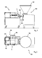
- Eine Maschine zum Füllen von schlauchförmigen Hüllen mit einer erfindungsgemäßen Füllvorrichtung;
- Figur 2:
- eine Draufsicht auf die Füllmaschine und die erfindungsgemäße Füllvorrichtung nach
Figur 1 ; - Figur 3:
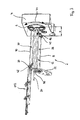
- eine perspektivische Ansicht einer erfindungsgemäßen Füllvorrichtung und einer damit gekoppelten Darmgreifvorrichtung für schlauchförmige Hüllen, und
- Figur 4:
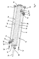
- eine perspektivische Teilansicht der die Füllrohre abstützenden Stützeinrichtung nach
Figur 3 .
- FIG. 1:
- A machine for filling tubular casings with a filling device according to the invention;
- FIG. 2:
- a plan view of the filling machine and the filling device according to the invention
FIG. 1 ; - FIG. 3:
- a perspective view of a filling device according to the invention and coupled thereto intestinal gripping device for tubular sheaths, and
- FIG. 4:
- a perspective partial view of the filling tubes supporting support means after
FIG. 3 ,
Die
Die
In
Wie aus
Mit der erfindungsgemäßen Füllvorrichtung 2 erfolgt das Aufziehen einer schlauchförmigen Hülle auf das Füllrohr 10 und das Füllen einer auf einem Füllrohr 8 aufgenommenen schlauchförmigen Hülle wie nachfolgend erläutert. Wie die
Nach Beendigung des Füllvorganges am Füllrohr 8 wird die Darmbremseinheit 22 vom offenen Ende 14' des Füllrohres 8 in Längsrichtung des Füllrohres heruntergezogen, und dann dass als Schwenkplatte ausgebildete Aufnahmeteil 6 um etwa 180° (Pfeil 44) verschwenkt, sodass nun mehr das zuvor obere und nun mehr mit der schlauchförmigen Hülle bestückte Füllrohr 10 in die untere Position verfahren wird und das leere Füllrohr 8 sich dann in der oberen Position befindet. Durch die an den Füllrohren 8, 10 angreifenden Stützelemente 18, 20 kann die Schwenkbewegung der Schwenkplatte 6 mit den Füllrohren um ihre Drehachse mit hoher Geschwindigkeit vorgenommen werden, da einem Schwingen der Füllrohre durch die Stützelemente entgegengewirkt wird. Nach erfolgtem Positionswechsel der Füllrohre kann nunmehr mit dem Füllvorgang am Füllrohr 10 und dem wiederholten Aufziehen der schlauchförmigen Hülle auf das Füllrohr 8 begonnen werden.After completion of the filling process on the filling
Claims (15)
eine am Aufnahmeteil (6) angeordnete Stützeinrichtung (12), welche ein in Längsrichtung des Füllrohres (8, 10) im Abstand (x) zum Aufnahmeteil (6) angeordnetes Stützelement (18, 20) für das Füllrohr (8, 10) aufweist, wobei das Stützelement (18, 20) zur Aufnahme von auf das Füllrohr (8, 10) wirkenden Querkräften eingerichtet ist.
a supporting device (12) arranged on the receiving part (6) and having a supporting element (18, 20) for the filling tube (8, 10) arranged in the longitudinal direction of the filling tube (8, 10) at a distance (x) from the receiving part (6), wherein the support element (18, 20) is adapted to receive transverse forces acting on the filling tube (8, 10).
dadurch gekennzeichnet, dass das Stützelement (18, 20) entlang des Füllrohres (8, 10) beweglich ist.Device according to claim 1,
characterized in that the support element (18, 20) along the filling tube (8, 10) is movable.
dadurch gekennzeichnet, dass am Aufnahmeteil (6) mehrere dreh- und antreibbare Füllrohre (8, 10) angeordnet sind, wobei jedes Füllrohr (8, 10) über ein in Längsrichtung im Abstand (x) zum Aufnahmeteil (6) angeordnetes Stützelement (18, 20) gelagert ist.Device according to one of claims 1 and 2,
characterized in that on the receiving part (6) a plurality of rotatable and drivable filling tubes (8, 10) are arranged, each filling tube (8, 10) via a longitudinally at a distance (x) to the receiving part (6) arranged supporting element (18, 20) is stored.
dadurch gekennzeichnet, dass das Aufnahmeteil (6) eine Schwenkplatte aufweist, die beweglich an der Vorrichtung (2) gehalten und an der jeweils das Füllrohr (8, 10) vorzugsweise waagerecht abstehend angeordnet ist.Device according to one of claims 1 to 3,
characterized in that the receiving part (6) has a pivot plate which is movably held on the device (2) and on which in each case the filling tube (8, 10) is preferably arranged projecting horizontally.
dadurch gekennzeichnet, dass die Schwenkplatte eine Drehachse aufweist, wobei die Drehachse der Schwenkplatte und jeweils die Drehachse des Füllrohres (8, 10) parallel zueinander ausgerichtet sind.Device according to claim 4,
characterized in that the pivot plate has an axis of rotation, wherein the axis of rotation of the pivot plate and in each case the axis of rotation of the filling tube (8, 10) are aligned parallel to each other.
dadurch gekennzeichnet, dass das Stützelement (18, 20) jeweils einen Führungsschlitten (24, 26) aufweist, welcher entlang einer parallel zur Längsachse des Füllrohres (8, 10) verlaufenden Führungsbahn (28, 30) der Stützeinrichtung (12) beweglich ist.Device according to one of claims 1 to 5,
characterized in that the support element (18, 20) each have a guide carriage (24, 26) which along a parallel to the longitudinal axis of the filling tube (8, 10) extending guideway (28, 30) of the support means (12) is movable.
dadurch gekennzeichnet, dass jede Führungsbahn (28, 30) zwei sich parallel zueinander erstreckende Führungsstreben (32, 32') aufweist.Device according to claim 6,
characterized in that each guide track (28, 30) has two guide struts (32, 32 ') extending parallel to each other.
dadurch gekennzeichnet, dass die Stützeinrichtung (12) eine koaxial zur Drehachse der Schwenkplatte (6) angeordnete Zentralstrebe (34) aufweist, zu der die Führungsstreben (32, 32') einer jeweiligen Führungsbahn (28, 30) parallel angeordnet sind.Device according to one of claims 4 to 7,
characterized in that the support means (12) has a coaxial with the axis of rotation of the pivot plate (6) arranged central strut (34) to which the guide struts (32, 32 ') of a respective guide track (28, 30) are arranged in parallel.
dadurch gekennzeichnet, dass die Enden der Führungsstreben (32, 32') beidseitig über jeweils einen Verbindungsflansch (36, 36') mit der Zentralstrebe (34) verbunden sind.Device according to claim 8,
characterized in that the ends of the guide struts (32, 32 ') on both sides via a respective connecting flange (36, 36') with the central strut (34) are connected.
dadurch gekennzeichnet, dass am freien Ende der Zentralstrebe (34) ein abschnittsweise entlang der Zentralstrebe bewegliches Führungsteil der Darmbremseinheit (22) angeordnet ist.Device according to one of claims 8 and 9,
characterized in that at the free end of the central strut (34) a partially along the central strut movable guide part of the intestinal brake unit (22) is arranged.
dadurch gekennzeichnet, dass jedes Stützelements (18, 20) ein Lagerteil (40, 40') aufweist, über das ein Darmmitnahmering (42, 42') drehbeweglich aufgenommen ist, der jeweils drehfest am Füllrohr (8, 10) aufgenommen und schiebbeweglich entlang des Füllrohres (8, 10) ist.Device according to one of claims 1 to 10,
characterized in that each support element (18, 20) has a bearing part (40, 40 ') via which a gutter ring (42, 42') is rotatably received, each rotatably received on the filling tube (8, 10) and slidably movable along the Filling tube (8, 10).
dadurch gekennzeichnet, dass das Stützelement (18, 20) dazu eingerichtet ist, während des Aufziehens der schlauchförmigen Hülle auf das Füllrohr (8, 10), vorzugsweise mittels einer Darmgreifvorrichtung (112) in Richtung des Aufnahmeteils (6) bewegt zu werden.Device according to one of claims 1 to 11,
characterized in that the support member (18, 20) is adapted to be moved during the winding of the tubular casing on the filling tube (8, 10), preferably by means of a gut gripping device (112) in the direction of the receiving part (6).
dadurch gekennzeichnet, dass das Stützelement (18, 20) eingerichtet ist, während des Füllens der schlauchförmigen Hülle, vorzugsweise mittels eines Darmschiebers, in Richtung des offenen Endes (14', 16') des Füllrohres (8, 10) verschoben zu werden.Device according to one of claims 1 to 12,
characterized in that the support element (18, 20) is adapted to be displaced during filling of the tubular casing, preferably by means of an intestinal slide, in the direction of the open end (14 ', 16') of the filling tube (8, 10).
gekennzeichnet durch ein Stützelement (18, 20) für das Füllrohr (8, 10), das in Längsrichtung des Füllrohres (8, 10) im Abstand (x) zu einem das Füllrohr drehbeweglich aufnehmenden Aufnahmeteil (6) anordenbar und zur Aufnahme von auf das Füllrohr (8, 10) wirkenden Querkräften eingerichtet ist, und wobei
die Stützeinrichtung zum Einsatz an einer Vorrichtung zum Füllen von schlauchförmigen Hüllen, nach einem der Ansprüche 1 bis 13, eingerichtet ist.Support device for at least one filling tube (8, 10) of a device for filling tubular casings with pasty mass, in particular of sausage meat sausage meat,
characterized by a support member (18, 20) for the filling tube (8, 10) in the longitudinal direction of the filling tube (8, 10) at a distance (x) to a receiving member (6) receiving the filling tube rotatably movable and for receiving on the Filling tube (8, 10) acting transverse forces is set, and wherein
the support device is adapted for use on a device for filling tubular casings, according to one of claims 1 to 13.
Priority Applications (1)
| Application Number | Priority Date | Filing Date | Title |
|---|---|---|---|
| PL14190850T PL2873324T3 (en) | 2013-11-13 | 2014-10-29 | Device for filling tubular casings |
Applications Claiming Priority (1)
| Application Number | Priority Date | Filing Date | Title |
|---|---|---|---|
| DE201320010285 DE202013010285U1 (en) | 2013-11-13 | 2013-11-13 | Device for filling tubular casings |
Publications (3)
| Publication Number | Publication Date |
|---|---|
| EP2873324A2 true EP2873324A2 (en) | 2015-05-20 |
| EP2873324A3 EP2873324A3 (en) | 2015-11-25 |
| EP2873324B1 EP2873324B1 (en) | 2017-07-26 |
Family
ID=51862127
Family Applications (1)
| Application Number | Title | Priority Date | Filing Date |
|---|---|---|---|
| EP14190850.9A Active EP2873324B1 (en) | 2013-11-13 | 2014-10-29 | Device for filling tubular casings |
Country Status (5)
| Country | Link |
|---|---|
| US (1) | US9314035B2 (en) |
| EP (1) | EP2873324B1 (en) |
| DE (1) | DE202013010285U1 (en) |
| ES (1) | ES2640881T3 (en) |
| PL (1) | PL2873324T3 (en) |
Families Citing this family (4)
| Publication number | Priority date | Publication date | Assignee | Title |
|---|---|---|---|---|
| US9622491B2 (en) * | 2015-04-01 | 2017-04-18 | Inox Meccanica S.R.L. | Automatic stuffing machine for food products |
| DE102017120108B3 (en) | 2017-08-31 | 2018-08-16 | Vemag Maschinenbau Gmbh | Device for filling tubular casings |
| DE102018110888B3 (en) * | 2018-05-07 | 2019-05-02 | Vemag Maschinenbau Gmbh | Method for loading a filling tube and device for filling tubular casings |
| DE202019106178U1 (en) * | 2019-11-06 | 2021-02-10 | Vemag Maschinenbau Gmbh | Casing holding device for a device for filling tubular casings |
Citations (1)
| Publication number | Priority date | Publication date | Assignee | Title |
|---|---|---|---|---|
| EP2040556B1 (en) | 2006-07-07 | 2011-01-12 | VEMAG Maschinenbau GmbH | Filling apparatus, machine and method for filling of casings, particularly sausage casings |
Family Cites Families (13)
| Publication number | Priority date | Publication date | Assignee | Title |
|---|---|---|---|---|
| US3964128A (en) * | 1972-12-14 | 1976-06-22 | Townsend Engineering Company | Apparatus for encasing a product |
| DE2610315C3 (en) * | 1976-03-12 | 1982-02-04 | Albert Handtmann Gmbh & Co, 7950 Biberach | Suspension device for sausages |
| DE3311567A1 (en) * | 1983-03-30 | 1984-10-04 | Karl 7065 Winterbach Schnell | MACHINE FOR FILLING DOUGH MEDIA, ESPECIALLY SAUSAGE BREAD |
| US4624029A (en) * | 1985-10-15 | 1986-11-25 | Tipper Tie, Inc. | Shirring device |
| US4893377A (en) * | 1988-01-06 | 1990-01-16 | Delaware Capital Formation, Inc. | Stuffing horn turret machine |
| US5277021A (en) | 1991-05-13 | 1994-01-11 | Sundstrand Corporation | Very high altitude turbine combustor |
| DE4135702C2 (en) * | 1991-10-30 | 1995-07-13 | Guenter Kollross | Device for gathering tubular packaging material, in particular artificial casings for sausage production |
| JP3596544B2 (en) * | 1992-04-30 | 2004-12-02 | ハイテック株式会社 | Chain sausage manufacturing equipment |
| ITMN20000007A1 (en) * | 2000-01-31 | 2001-07-31 | Inox Meccanica Srl | DEVICE IN PORTIONING-BAGGING MACHINE FOR CONNECTION WITH CLIPPING MACHINE |
| DE10123808A1 (en) * | 2001-05-16 | 2002-11-21 | Frey Heinrich Maschinenbau | Sausage filling rotating tube has surrounding jacket with flexible end-section |
| DE102007061119A1 (en) * | 2007-12-19 | 2009-06-25 | Heinrich Frey Maschinenbau Gmbh | Casing holding device |
| ES2365990T5 (en) * | 2009-03-13 | 2014-05-08 | Albert Handtmann Maschinenfabrik Gmbh & Co. Kg | Clamping device |
| ATE520309T1 (en) * | 2009-06-24 | 2011-09-15 | Handtmann Albert Maschf | DEVICE FOR FILLING INTESTINES |
-
2013
- 2013-11-13 DE DE201320010285 patent/DE202013010285U1/en not_active Expired - Lifetime
-
2014
- 2014-10-29 PL PL14190850T patent/PL2873324T3/en unknown
- 2014-10-29 EP EP14190850.9A patent/EP2873324B1/en active Active
- 2014-10-29 ES ES14190850.9T patent/ES2640881T3/en active Active
- 2014-11-03 US US14/531,321 patent/US9314035B2/en active Active
Patent Citations (1)
| Publication number | Priority date | Publication date | Assignee | Title |
|---|---|---|---|---|
| EP2040556B1 (en) | 2006-07-07 | 2011-01-12 | VEMAG Maschinenbau GmbH | Filling apparatus, machine and method for filling of casings, particularly sausage casings |
Also Published As
| Publication number | Publication date |
|---|---|
| DE202013010285U1 (en) | 2015-03-06 |
| ES2640881T3 (en) | 2017-11-07 |
| EP2873324A3 (en) | 2015-11-25 |
| EP2873324B1 (en) | 2017-07-26 |
| PL2873324T3 (en) | 2018-01-31 |
| US9314035B2 (en) | 2016-04-19 |
| US20150245627A1 (en) | 2015-09-03 |
Similar Documents
| Publication | Publication Date | Title |
|---|---|---|
| DE102017120108B3 (en) | Device for filling tubular casings | |
| EP1844659B1 (en) | Direct connection of sausage clip and sausage handling device | |
| EP1897446B1 (en) | Production line for manufacturing sausage-shaped products | |
| EP0424675B1 (en) | Method and device for mechanized suspension of sausages | |
| EP0962143B1 (en) | Device for manufacturing sausages | |
| DE102008026095B4 (en) | Method and apparatus for applying a wrapper for food products, such as e.g. Sausages, on a stuffing tube | |
| DE102007011422B3 (en) | Plait-forming device e.g. for sausage, has drive force transmission unit transmitting drive force generated by drive unit, on displacement shear pair and swivelable reversibly about swivel point, where position of swivel point is adjustable | |
| EP0025923A1 (en) | Method and device for the automated production of string sausages while using synthetic casing material for the sausage skins | |
| EP2873324B1 (en) | Device for filling tubular casings | |
| DE3502274C2 (en) | Device for applying a sausage chain in particular to a smoke stick | |
| DE2610315B2 (en) | Suspension device for sausages | |
| DE3907488A1 (en) | METHOD FOR PACKAGING A HOSE SECTION SECTORED TO A HOLLOW CYLINDRICAL Caterpillar INTO A HOSE NET FOR LATER PROCESSING AS A SAUSAGE CASE ON A SAUSAGE MACHINE | |
| EP1767096A1 (en) | Apparatus and method for portioning food | |
| DE3244064A1 (en) | METHOD AND DEVICE FOR INACTIVELY LOADING THE FILLING TUBE OF A SAUSAGE FILLER AND SEALING MACHINE WITH FULLY FINISHED HOSE SLEEVE SECTIONS | |
| DE202006019883U1 (en) | Production line for production of sausages shaped products, has control device is provided in position to regulate speed of conveying element of the loading machine on basis of control variable derived from clipping | |
| EP2225948B1 (en) | Feed device for suspension elements | |
| DE202009014671U1 (en) | Portioning and / or transporting device for portioning and / or transporting sausages or other elongated food products | |
| EP3318131B1 (en) | Suspension device and method for removing a sausage group | |
| EP0131753A1 (en) | Method and device for shirring tubular casings | |
| DE60310589T2 (en) | METHOD AND MEANS FOR QUICKLY LOADING SLEEVE BEARINGS ON A SAUSAGE MANUFACTURER | |
| DE2749947A1 (en) | FILTER PRODUCTION MACHINE | |
| EP1874122B1 (en) | Device for filling packing wrappers with stuffing | |
| DE8612520U1 (en) | Device for wrapping a product | |
| DE2941872A1 (en) | Machine for making sausages with synthetic skins - has bath to moisten skin immediately before filling | |
| DE2724424C2 (en) | Device for depositing balls of yarn in the buckets of a conveyor belt |
Legal Events
| Date | Code | Title | Description |
|---|---|---|---|
| PUAI | Public reference made under article 153(3) epc to a published international application that has entered the european phase |
Free format text: ORIGINAL CODE: 0009012 |
|
| 17P | Request for examination filed |
Effective date: 20141029 |
|
| AK | Designated contracting states |
Kind code of ref document: A2 Designated state(s): AL AT BE BG CH CY CZ DE DK EE ES FI FR GB GR HR HU IE IS IT LI LT LU LV MC MK MT NL NO PL PT RO RS SE SI SK SM TR |
|
| AX | Request for extension of the european patent |
Extension state: BA ME |
|
| PUAL | Search report despatched |
Free format text: ORIGINAL CODE: 0009013 |
|
| AK | Designated contracting states |
Kind code of ref document: A3 Designated state(s): AL AT BE BG CH CY CZ DE DK EE ES FI FR GB GR HR HU IE IS IT LI LT LU LV MC MK MT NL NO PL PT RO RS SE SI SK SM TR |
|
| AX | Request for extension of the european patent |
Extension state: BA ME |
|
| RIC1 | Information provided on ipc code assigned before grant |
Ipc: A22C 11/02 20060101AFI20151021BHEP |
|
| R17P | Request for examination filed (corrected) |
Effective date: 20160525 |
|
| RBV | Designated contracting states (corrected) |
Designated state(s): AL AT BE BG CH CY CZ DE DK EE ES FI FR GB GR HR HU IE IS IT LI LT LU LV MC MK MT NL NO PL PT RO RS SE SI SK SM TR |
|
| GRAP | Despatch of communication of intention to grant a patent |
Free format text: ORIGINAL CODE: EPIDOSNIGR1 |
|
| INTG | Intention to grant announced |
Effective date: 20170316 |
|
| GRAS | Grant fee paid |
Free format text: ORIGINAL CODE: EPIDOSNIGR3 |
|
| GRAA | (expected) grant |
Free format text: ORIGINAL CODE: 0009210 |
|
| AK | Designated contracting states |
Kind code of ref document: B1 Designated state(s): AL AT BE BG CH CY CZ DE DK EE ES FI FR GB GR HR HU IE IS IT LI LT LU LV MC MK MT NL NO PL PT RO RS SE SI SK SM TR |
|
| REG | Reference to a national code |
Ref country code: GB Ref legal event code: FG4D Free format text: NOT ENGLISH |
|
| REG | Reference to a national code |
Ref country code: CH Ref legal event code: EP |
|
| REG | Reference to a national code |
Ref country code: AT Ref legal event code: REF Ref document number: 911633 Country of ref document: AT Kind code of ref document: T Effective date: 20170815 |
|
| REG | Reference to a national code |
Ref country code: IE Ref legal event code: FG4D Free format text: LANGUAGE OF EP DOCUMENT: GERMAN |
|
| REG | Reference to a national code |
Ref country code: DE Ref legal event code: R096 Ref document number: 502014004722 Country of ref document: DE |
|
| REG | Reference to a national code |
Ref country code: FR Ref legal event code: PLFP Year of fee payment: 4 |
|
| REG | Reference to a national code |
Ref country code: NL Ref legal event code: FP |
|
| REG | Reference to a national code |
Ref country code: ES Ref legal event code: FG2A Ref document number: 2640881 Country of ref document: ES Kind code of ref document: T3 Effective date: 20171107 |
|
| REG | Reference to a national code |
Ref country code: LT Ref legal event code: MG4D |
|
| PG25 | Lapsed in a contracting state [announced via postgrant information from national office to epo] |
Ref country code: LT Free format text: LAPSE BECAUSE OF FAILURE TO SUBMIT A TRANSLATION OF THE DESCRIPTION OR TO PAY THE FEE WITHIN THE PRESCRIBED TIME-LIMIT Effective date: 20170726 Ref country code: FI Free format text: LAPSE BECAUSE OF FAILURE TO SUBMIT A TRANSLATION OF THE DESCRIPTION OR TO PAY THE FEE WITHIN THE PRESCRIBED TIME-LIMIT Effective date: 20170726 Ref country code: NO Free format text: LAPSE BECAUSE OF FAILURE TO SUBMIT A TRANSLATION OF THE DESCRIPTION OR TO PAY THE FEE WITHIN THE PRESCRIBED TIME-LIMIT Effective date: 20171026 Ref country code: SE Free format text: LAPSE BECAUSE OF FAILURE TO SUBMIT A TRANSLATION OF THE DESCRIPTION OR TO PAY THE FEE WITHIN THE PRESCRIBED TIME-LIMIT Effective date: 20170726 Ref country code: HR Free format text: LAPSE BECAUSE OF FAILURE TO SUBMIT A TRANSLATION OF THE DESCRIPTION OR TO PAY THE FEE WITHIN THE PRESCRIBED TIME-LIMIT Effective date: 20170726 |
|
| PG25 | Lapsed in a contracting state [announced via postgrant information from national office to epo] |
Ref country code: RS Free format text: LAPSE BECAUSE OF FAILURE TO SUBMIT A TRANSLATION OF THE DESCRIPTION OR TO PAY THE FEE WITHIN THE PRESCRIBED TIME-LIMIT Effective date: 20170726 Ref country code: IS Free format text: LAPSE BECAUSE OF FAILURE TO SUBMIT A TRANSLATION OF THE DESCRIPTION OR TO PAY THE FEE WITHIN THE PRESCRIBED TIME-LIMIT Effective date: 20171126 Ref country code: LV Free format text: LAPSE BECAUSE OF FAILURE TO SUBMIT A TRANSLATION OF THE DESCRIPTION OR TO PAY THE FEE WITHIN THE PRESCRIBED TIME-LIMIT Effective date: 20170726 Ref country code: BG Free format text: LAPSE BECAUSE OF FAILURE TO SUBMIT A TRANSLATION OF THE DESCRIPTION OR TO PAY THE FEE WITHIN THE PRESCRIBED TIME-LIMIT Effective date: 20171026 Ref country code: GR Free format text: LAPSE BECAUSE OF FAILURE TO SUBMIT A TRANSLATION OF THE DESCRIPTION OR TO PAY THE FEE WITHIN THE PRESCRIBED TIME-LIMIT Effective date: 20171027 |
|
| PG25 | Lapsed in a contracting state [announced via postgrant information from national office to epo] |
Ref country code: RO Free format text: LAPSE BECAUSE OF FAILURE TO SUBMIT A TRANSLATION OF THE DESCRIPTION OR TO PAY THE FEE WITHIN THE PRESCRIBED TIME-LIMIT Effective date: 20170726 Ref country code: CZ Free format text: LAPSE BECAUSE OF FAILURE TO SUBMIT A TRANSLATION OF THE DESCRIPTION OR TO PAY THE FEE WITHIN THE PRESCRIBED TIME-LIMIT Effective date: 20170726 Ref country code: DK Free format text: LAPSE BECAUSE OF FAILURE TO SUBMIT A TRANSLATION OF THE DESCRIPTION OR TO PAY THE FEE WITHIN THE PRESCRIBED TIME-LIMIT Effective date: 20170726 |
|
| REG | Reference to a national code |
Ref country code: DE Ref legal event code: R097 Ref document number: 502014004722 Country of ref document: DE |
|
| PG25 | Lapsed in a contracting state [announced via postgrant information from national office to epo] |
Ref country code: SK Free format text: LAPSE BECAUSE OF FAILURE TO SUBMIT A TRANSLATION OF THE DESCRIPTION OR TO PAY THE FEE WITHIN THE PRESCRIBED TIME-LIMIT Effective date: 20170726 Ref country code: IT Free format text: LAPSE BECAUSE OF FAILURE TO SUBMIT A TRANSLATION OF THE DESCRIPTION OR TO PAY THE FEE WITHIN THE PRESCRIBED TIME-LIMIT Effective date: 20170726 Ref country code: MC Free format text: LAPSE BECAUSE OF FAILURE TO SUBMIT A TRANSLATION OF THE DESCRIPTION OR TO PAY THE FEE WITHIN THE PRESCRIBED TIME-LIMIT Effective date: 20170726 Ref country code: SM Free format text: LAPSE BECAUSE OF FAILURE TO SUBMIT A TRANSLATION OF THE DESCRIPTION OR TO PAY THE FEE WITHIN THE PRESCRIBED TIME-LIMIT Effective date: 20170726 Ref country code: EE Free format text: LAPSE BECAUSE OF FAILURE TO SUBMIT A TRANSLATION OF THE DESCRIPTION OR TO PAY THE FEE WITHIN THE PRESCRIBED TIME-LIMIT Effective date: 20170726 |
|
| REG | Reference to a national code |
Ref country code: CH Ref legal event code: PL |
|
| PLBE | No opposition filed within time limit |
Free format text: ORIGINAL CODE: 0009261 |
|
| STAA | Information on the status of an ep patent application or granted ep patent |
Free format text: STATUS: NO OPPOSITION FILED WITHIN TIME LIMIT |
|
| 26N | No opposition filed |
Effective date: 20180430 |
|
| REG | Reference to a national code |
Ref country code: IE Ref legal event code: MM4A |
|
| PG25 | Lapsed in a contracting state [announced via postgrant information from national office to epo] |
Ref country code: LU Free format text: LAPSE BECAUSE OF NON-PAYMENT OF DUE FEES Effective date: 20171029 Ref country code: CH Free format text: LAPSE BECAUSE OF NON-PAYMENT OF DUE FEES Effective date: 20171031 Ref country code: LI Free format text: LAPSE BECAUSE OF NON-PAYMENT OF DUE FEES Effective date: 20171031 |
|
| REG | Reference to a national code |
Ref country code: BE Ref legal event code: MM Effective date: 20171031 |
|
| PG25 | Lapsed in a contracting state [announced via postgrant information from national office to epo] |
Ref country code: SI Free format text: LAPSE BECAUSE OF FAILURE TO SUBMIT A TRANSLATION OF THE DESCRIPTION OR TO PAY THE FEE WITHIN THE PRESCRIBED TIME-LIMIT Effective date: 20170726 Ref country code: BE Free format text: LAPSE BECAUSE OF NON-PAYMENT OF DUE FEES Effective date: 20171031 |
|
| PG25 | Lapsed in a contracting state [announced via postgrant information from national office to epo] |
Ref country code: MT Free format text: LAPSE BECAUSE OF FAILURE TO SUBMIT A TRANSLATION OF THE DESCRIPTION OR TO PAY THE FEE WITHIN THE PRESCRIBED TIME-LIMIT Effective date: 20170726 |
|
| REG | Reference to a national code |
Ref country code: FR Ref legal event code: PLFP Year of fee payment: 5 |
|
| PG25 | Lapsed in a contracting state [announced via postgrant information from national office to epo] |
Ref country code: IE Free format text: LAPSE BECAUSE OF NON-PAYMENT OF DUE FEES Effective date: 20171029 |
|
| PG25 | Lapsed in a contracting state [announced via postgrant information from national office to epo] |
Ref country code: HU Free format text: LAPSE BECAUSE OF FAILURE TO SUBMIT A TRANSLATION OF THE DESCRIPTION OR TO PAY THE FEE WITHIN THE PRESCRIBED TIME-LIMIT; INVALID AB INITIO Effective date: 20141029 |
|
| PG25 | Lapsed in a contracting state [announced via postgrant information from national office to epo] |
Ref country code: CY Free format text: LAPSE BECAUSE OF FAILURE TO SUBMIT A TRANSLATION OF THE DESCRIPTION OR TO PAY THE FEE WITHIN THE PRESCRIBED TIME-LIMIT Effective date: 20170726 |
|
| PG25 | Lapsed in a contracting state [announced via postgrant information from national office to epo] |
Ref country code: MK Free format text: LAPSE BECAUSE OF FAILURE TO SUBMIT A TRANSLATION OF THE DESCRIPTION OR TO PAY THE FEE WITHIN THE PRESCRIBED TIME-LIMIT Effective date: 20170726 |
|
| PG25 | Lapsed in a contracting state [announced via postgrant information from national office to epo] |
Ref country code: PT Free format text: LAPSE BECAUSE OF FAILURE TO SUBMIT A TRANSLATION OF THE DESCRIPTION OR TO PAY THE FEE WITHIN THE PRESCRIBED TIME-LIMIT Effective date: 20170726 |
|
| PG25 | Lapsed in a contracting state [announced via postgrant information from national office to epo] |
Ref country code: AL Free format text: LAPSE BECAUSE OF FAILURE TO SUBMIT A TRANSLATION OF THE DESCRIPTION OR TO PAY THE FEE WITHIN THE PRESCRIBED TIME-LIMIT Effective date: 20170726 |
|
| PGFP | Annual fee paid to national office [announced via postgrant information from national office to epo] |
Ref country code: TR Payment date: 20211026 Year of fee payment: 8 |
|
| PGFP | Annual fee paid to national office [announced via postgrant information from national office to epo] |
Ref country code: PL Payment date: 20220922 Year of fee payment: 9 |
|
| PGFP | Annual fee paid to national office [announced via postgrant information from national office to epo] |
Ref country code: NL Payment date: 20231023 Year of fee payment: 10 |
|
| PGFP | Annual fee paid to national office [announced via postgrant information from national office to epo] |
Ref country code: GB Payment date: 20231025 Year of fee payment: 10 |
|
| PGFP | Annual fee paid to national office [announced via postgrant information from national office to epo] |
Ref country code: ES Payment date: 20231117 Year of fee payment: 10 |
|
| PGFP | Annual fee paid to national office [announced via postgrant information from national office to epo] |
Ref country code: FR Payment date: 20231023 Year of fee payment: 10 Ref country code: DE Payment date: 20231109 Year of fee payment: 10 Ref country code: AT Payment date: 20231019 Year of fee payment: 10 |