EP2871150B1 - Unité et procédé de remplissage d'un article avec un produit liquide - Google Patents
Unité et procédé de remplissage d'un article avec un produit liquide Download PDFInfo
- Publication number
- EP2871150B1 EP2871150B1 EP13192230.4A EP13192230A EP2871150B1 EP 2871150 B1 EP2871150 B1 EP 2871150B1 EP 13192230 A EP13192230 A EP 13192230A EP 2871150 B1 EP2871150 B1 EP 2871150B1
- Authority
- EP
- European Patent Office
- Prior art keywords
- filling
- article
- aeriform
- fluidic line
- valve
- Prior art date
- Legal status (The legal status is an assumption and is not a legal conclusion. Google has not performed a legal analysis and makes no representation as to the accuracy of the status listed.)
- Active
Links
- 238000000034 method Methods 0.000 title claims description 10
- 235000013305 food Nutrition 0.000 claims description 49
- 239000012530 fluid Substances 0.000 claims description 9
- 239000007789 gas Substances 0.000 description 84
- CURLTUGMZLYLDI-UHFFFAOYSA-N Carbon dioxide Chemical compound O=C=O CURLTUGMZLYLDI-UHFFFAOYSA-N 0.000 description 14
- 229910002092 carbon dioxide Inorganic materials 0.000 description 7
- 239000001569 carbon dioxide Substances 0.000 description 7
- IJGRMHOSHXDMSA-UHFFFAOYSA-N Atomic nitrogen Chemical compound N#N IJGRMHOSHXDMSA-UHFFFAOYSA-N 0.000 description 4
- 239000012535 impurity Substances 0.000 description 3
- 239000000356 contaminant Substances 0.000 description 2
- 238000004880 explosion Methods 0.000 description 2
- 238000005187 foaming Methods 0.000 description 2
- 229910052757 nitrogen Inorganic materials 0.000 description 2
- MGWGWNFMUOTEHG-UHFFFAOYSA-N 4-(3,5-dimethylphenyl)-1,3-thiazol-2-amine Chemical compound CC1=CC(C)=CC(C=2N=C(N)SC=2)=C1 MGWGWNFMUOTEHG-UHFFFAOYSA-N 0.000 description 1
- 239000003795 chemical substances by application Substances 0.000 description 1
- 230000007613 environmental effect Effects 0.000 description 1
- 230000005484 gravity Effects 0.000 description 1
- 238000012986 modification Methods 0.000 description 1
- 230000004048 modification Effects 0.000 description 1
- JCXJVPUVTGWSNB-UHFFFAOYSA-N nitrogen dioxide Inorganic materials O=[N]=O JCXJVPUVTGWSNB-UHFFFAOYSA-N 0.000 description 1
- 230000002093 peripheral effect Effects 0.000 description 1
- 239000000126 substance Substances 0.000 description 1
- 238000011144 upstream manufacturing Methods 0.000 description 1
Images

Classifications
-
- B—PERFORMING OPERATIONS; TRANSPORTING
- B67—OPENING, CLOSING OR CLEANING BOTTLES, JARS OR SIMILAR CONTAINERS; LIQUID HANDLING
- B67C—CLEANING, FILLING WITH LIQUIDS OR SEMILIQUIDS, OR EMPTYING, OF BOTTLES, JARS, CANS, CASKS, BARRELS, OR SIMILAR CONTAINERS, NOT OTHERWISE PROVIDED FOR; FUNNELS
- B67C3/00—Bottling liquids or semiliquids; Filling jars or cans with liquids or semiliquids using bottling or like apparatus; Filling casks or barrels with liquids or semiliquids
- B67C3/007—Applications of control, warning or safety devices in filling machinery
-
- B—PERFORMING OPERATIONS; TRANSPORTING
- B67—OPENING, CLOSING OR CLEANING BOTTLES, JARS OR SIMILAR CONTAINERS; LIQUID HANDLING
- B67C—CLEANING, FILLING WITH LIQUIDS OR SEMILIQUIDS, OR EMPTYING, OF BOTTLES, JARS, CANS, CASKS, BARRELS, OR SIMILAR CONTAINERS, NOT OTHERWISE PROVIDED FOR; FUNNELS
- B67C3/00—Bottling liquids or semiliquids; Filling jars or cans with liquids or semiliquids using bottling or like apparatus; Filling casks or barrels with liquids or semiliquids
- B67C3/02—Bottling liquids or semiliquids; Filling jars or cans with liquids or semiliquids using bottling or like apparatus
- B67C3/06—Bottling liquids or semiliquids; Filling jars or cans with liquids or semiliquids using bottling or like apparatus using counterpressure, i.e. filling while the container is under pressure
- B67C3/12—Pressure-control devices
-
- B—PERFORMING OPERATIONS; TRANSPORTING
- B67—OPENING, CLOSING OR CLEANING BOTTLES, JARS OR SIMILAR CONTAINERS; LIQUID HANDLING
- B67C—CLEANING, FILLING WITH LIQUIDS OR SEMILIQUIDS, OR EMPTYING, OF BOTTLES, JARS, CANS, CASKS, BARRELS, OR SIMILAR CONTAINERS, NOT OTHERWISE PROVIDED FOR; FUNNELS
- B67C3/00—Bottling liquids or semiliquids; Filling jars or cans with liquids or semiliquids using bottling or like apparatus; Filling casks or barrels with liquids or semiliquids
- B67C3/02—Bottling liquids or semiliquids; Filling jars or cans with liquids or semiliquids using bottling or like apparatus
- B67C3/22—Details
- B67C3/28—Flow-control devices, e.g. using valves
Definitions
- the present invention relates to a filling unit for contact or contactless filling an article with a pourable product, especially a pourable food product.
- the present invention also relates to a filling method for contact or contactless filling an article with the pourable product, especially a pourable food product.
- the filling device is adapted either to fill the article with a carbonated food product, i.e. a food product containing carbon dioxide, according to a contact modality or to fill the article with a still pourable product according a contactless modality.
- a carbonated food product i.e. a food product containing carbon dioxide
- Known article-handling machines comprise a filling station fed with empty articles and adapted to output articles filled with the pourable food product.
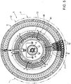
- the filling unit substantially comprises a carousel conveyor rotating about a rotation axis, a tank containing the pourable food product, and a plurality of filling devices supported by the carousel conveyor in a position radially external with respect to the rotation axis of the carousel conveyor.
- the carousel is provided with a plurality of support elements for respective articles provided to arrange the mouths of respective articles in a lower position with respect to the respective filling devices and to displace the articles along a circumferential arc trajectory about the above said rotation axis integrally to the respective filling devices.
- Each filling device essentially comprises a fixed body connected to the carousel and a shutter sliding with respect to the fixed body between an open configuration and a closed configuration.
- the shutter when it is arranged in the open configuration, the shutter defines an opening with the fixed body.
- the pourable product thereby flows from the tank to a filling mouth of the relative article passing through the opening.
- the shutter when the shutter is arranged in the closed configuration, it sealingly cooperates with an abutment surface defined by the fixed body, thus preventing the pourable product from flowing from tank towards the mouth of the relative article.
- the body of the filling device is arranged at a given distance from the mouth of the article to be filled.
- the filling device is required to carry out a plurality of additional operations on the articles, in addition to the filling with the pourable food product.
- the articles undergo a pressurization operation before the filling thereof with the pourable food product.
- the empty articles are filled with a pressurized gas, so as to render the pressure inside the articles equal to the pressure of the pourable product, during the filling operation.
- the filling chamber is divided in a upper part filled with the pourable product and a lower part which faces the mouth of the article.
- the filling device shown in US-A-2001/0045242 comprises:
- control valves can be controlled to fluidly connect the return duct with the pressurization chamber, during the filling of the article.
- the shutter In case of filling with carbonated products, the shutter is kept in the closed configuration while the mouth of the article is in tight-fluid contact with the body of the filling device, and the control valves are controlled to allow the flow of the pressurized gas from the upper part of the tank towards the lower part of the filling device.
- the article is pressurized before the filling thereof.
- control valves are controlled to prevent the pressurized gas from flowing towards the filling device, and the shutter is set in the open configuration.
- the food product flows inside the inner volume of the article while the gas contained in the article flows back in the return duct and in the fluidic line towards the pressurization chamber and the upper part of the tank.
- the gas previously contained in the article mixes inside the pressurization chamber and the fluidic line with the gas coming from the tank and that has not yet reached the article.
- the gas that returns back along the return duct has been in contact with the article and, therefore, contains a certain amount of impurities.
- the gas with some impurities coming from the duct contaminates inside the chamber the "clean" pressurized gas coming from the upper part of the tank.
- the pressurized gas which eventually pressurizes the inner volume of the article inevitably contains some impurities.
- the filling device also needs to de-pressurize the article, after that the filling thereof with the food product has been completed.
- EP 1 216 952 A2 discloses a filling device according to the preamble of claim 1.
- the aforementioned object is achieved by the present invention as it relates to a filling device for contact or contactless filling device for filling an article with a pourable product, as defined in claim 1.
- the present invention also relates to a method for contact or contactless filling an article with a pourable product, as defined in claim 12.
- numeral 1 indicates a filling unit for filling articles 2 with a pourable product.
- Filling unit 1 is adapted either to contactless fill article 2 with a still food product or to contact fill article 2 with a carbonated food product, i.e. a food product containing carbon dioxide.
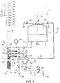
- filling unit 1 essentially comprises ( Figures 5 and 6 ):
- Carousel 3 also includes a tank 6 common to all filling devices 10 and which comprises a lower portion 7 filled with the pourable food product at a pressure higher than environment pressure and an upper portion 8 filled with a gas.
- gas is a pressurization gas, e.g. carbon dioxide, in case of contact filling of carbonated products.
- the gas is flown inside article 2 before the filling thereof, so as to render equal the pressure in the inner volume of articles 2 and the pressure of the pourable product inside portion 7 of tank 6.
- the gas contained in portion 8 is typically air or nitrogen and is flown through portion 8 of tank 6, so as to prevent contaminant substances to enter inside tank 6 and to contaminate the pourable food product.
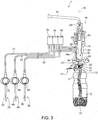
- Each article 2 comprises ( Figures 1 to 4 ):
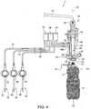
- Filling device 10 essentially comprises ( Figures 3 and 4 ) :
- Gripping device 17 is movable together and synchronously with filling device 10 and carousel 3 about axis A.
- gripping device 17 is movable parallel to axis B between:
- gripping device 17 moves from the lowered rest position to the raised operative position at station I and moves from the raised operative position to the lowered rest position at station O.
- Body 19 comprises, in turn, proceeding along axis B:
- filling unit 1 comprises, for each filling device 10, a fluidic line 14 interposed between lower portion 7 of tank 6 and openings 20 of filling devices 10, and along which a flow-sensor 29, a flow-meter in the embodiment shown, is arranged.
- Protrusion 22 is axially interposed between openings 20, 21, proceeding along axis B.
- passage 24 is, in a section orthogonal to axis B, shaped as a circle, the food product creates a cylindrical flow of axis B, during the filling of article 2.
- shutter 16 comprises:
- Plunger 25 is conical of axis B and comprises a conical end on the side of opening 21 shaped correspondingly to the shape of opening 21.
- protrusion 22 is conical of axis B and tapers from opening 20 to opening 21.
- Shutter 16 is movable relative to body 19 and along axis B between:
- the expression contact filling indicates a filling modality, in which article 2 is tight-fluidly pressed against body 19 of filling device 10 whereas the expression contactless filling indicates a filling modality, in which article 2 is spaced along axis B from body 19 of filling device 10.
- the food product is prevented from contacting the outer environment in case of contact filling whereas the food product contacts the outer environment in case of contactless filling.
- plunger 25 when shutter 16 is in the open configuration, plunger 25 is spaced from protrusion 22 and leaves free passage 24.
- plunger 25 abuts against protrusion 22 and seals passage 24.
- mouth 11 of article 2 is tight-fluidly pressed against opening 21 of filling device 10 in case of contact filling, when gripping device 17 is in the raised position.
- mouth 11 of article 2 is spaced along axis B from opening 21 of filling device 10 in case of contactless filling, when gripping device 17 is in the raised position.
- Body 19 also comprise a plurality, three in the embodiment shown, of ducts 18a, 18b, 18c (only schematically shown in Figures 1 and 2 ), which extend eccentrically to and on one side only of axis B and are arranged radially outer than shutter 16 with respect to axis B (see Figures 3 and 4 ).
- each duct 18a, 18b, 18c comprises an end opening 30. Openings 30 open inside body 19 in a position axially interposed along axis B between protrusion 22 and opening 21, i.e. inside cavities 31.
- openings 30 are in fluid connection with mouth 11 of article 2, even when shutter 16 is in the closed configuration.
- each duct 18a, 18b, 18c comprises:
- Portion 27 converge towards axis B on the opposite side of portion 26, in the embodiment shown.
- Portion 28 is, in the embodiment shown, radial to axis B.
- Filling unit 1 also comprises ( Figures 1 and 2 ) a plurality of fluidic lines 35, which are adapted to selectively convey the pressurization gas from upper portion 8 of tank 6 inside the inner volume of relative articles 2, in case of contact filling.
- fluidic lines 35 comprise:
- Filling unit 1 also comprises:
- Valve 41 may be selectively arranged in:
- Each valve 42 may be selectively arranged in:
- Filling unit 1 also comprises a control unit 45 (only schematically shown in Figures 1 and 2 ) configured to valves 41, 42 and shutters 16 of filling device 10 in such a way to pressurize articles 2 with gas contained in upper portion 7 of tank 6, before the contact filling of articles 2 with carbonated food product.
- a control unit 45 (only schematically shown in Figures 1 and 2 ) configured to valves 41, 42 and shutters 16 of filling device 10 in such a way to pressurize articles 2 with gas contained in upper portion 7 of tank 6, before the contact filling of articles 2 with carbonated food product.
- control unit 45 is configured, in case of contact filling of articles 2 with carbonated food product, to:
- Filling unit 1 also comprises ( Figures 1 and 2 ):
- Filling unit 1 comprises, for each filling device 10 and corresponding article 2,:
- each fluidic line 35 is fluidly isolated from corresponding fluidic line 44, i.e. the gas coming out from each article 2 along respective fluidic line 44 is prevented from reaching corresponding fluidic lines 35.
- fluidic lines 35, 44 are not required to be physically isolated from one another, but a preferential flow of the gas contained in upper portion 8 of tank 6 is established (as indicated by arrows in Figures 1 and 2 ):
- fluidic lines 44 comprises, proceeding from the inner volume of relative articles 2 towards discharge 55,:
- Each valve 46 is, in the embodiment shown, interposed along a relative portion 47 of the corresponding fluidic line 44.
- Filling unit 1 comprises a duct 60, which is interposed between pressurization chamber 40 and portion 49, and is connected to portion 49 at a connection point 61.
- common portion 49 of fluidic lines 44 comprises, proceeding from return gas chamber 48 to discharge 55,:
- Filling unit 1 further comprises:
- Means 62, 63 are throttlings, in the embodiment shown.
- Pressurization chamber 40 is at a first value of pressure
- return gas chamber 48 is at a second value of pressure
- discharge 55 is a third value of pressure.
- the first value of pressure is greater than the second value of pressure, and the second value of pressure is greater than the third value of pressure.
- the difference of pressure between pressurization chamber 40 and return gas chamber 48 is generated by the distributed hydraulic losses along segment 56 and duct 60, and by the concentrated hydraulic losses 62, 63.
- the gas preferentially moves from chamber 40 to inner volumes of articles 2 before the contact filling thereof, and from the inner volumes of article 2 to return gas chamber 48 and from return gas chamber 48 to discharge 55 before the contact filling of articles 2.
- Filling unit 1 also comprises a modulating valve 59 which is interposed along fluidic line 44 and adapted to generate a counter-pressure at the end of fluidic line 44.
- modulating valve 59 is interposed along portion 49 of filling line 44.
- control unit 45 is programmed for controlling valves 39, 41 in such a way that a substantially constant amount of gas passes through portion 8 of tank 6, thus ensuring the asepticity of the food product contained inside portion 7 of tank 6.
- control unit 45 is programmed to set, during the contactless filling of articles 2, corresponding valves 42 in the respective open configuration, so as to allow the gas coming out along fluidic line 35 to discharge from opening 30 of duct 18a inside cavities 31 and, then, inside, the outer environment ( Figure 3 ).
- the gas coming from upper portion 8 of tank 6 is discharged in the area between openings 21 of filling devices 10 and relative mouths 11 of articles 2, which are arranged at a given distance along axis B from respective filling devices 10.
- control unit 45 is also programmed to set, during the contactless filling of articles 2, also corresponding valves 46 in the respective open configurations, so as to allow the gas coming out along fluidic line 35 to discharge from openings 30 of ducts 18b inside cavities 31 and, then, inside the outer environment through openings 21 ( Figure 3 ).
- the gas coming from upper portion 8 of tank 6 is discharged in the area between openings 21 of filling devices 10 and relative mouths 11 of articles 2, which are arranged at a given distance along axis B from respective filling devices 10.
- filling unit 1 comprises:
- each fluidic line 70 extends between opening 32 of duct 18c to a drain 80 at the atmospheric pressure.
- Fluidic lines 70 comprise, proceeding from opening 30 of ducts 18c to drain 80,:
- Valves 75 are interposed between ducts 18c and respective portions 71.
- Control unit 45 is programmed for:
- pressurization chamber 40, return gas chamber 48 and de-pressurization chamber 72 are annular about axis A.
- valves 42, 46, 75 are on-off valves.
- filling unit 1 will be firstly described with reference to a contact filling operation with a carbonated product and with reference to only one filling device 10 and respective only one article 2 and only one gripping device 17, and to only one respective filling line 35, 44, 70 ( Figures 1 and 3 ).
- Portion 8 of tank 6 is filled with a pressurization gas, e.g. carbon dioxide while portion 7 of tank 6 is filled with the food product with which article 2 will be filled.
- a pressurization gas e.g. carbon dioxide
- portion 7 of tank 6 is filled with the food product with which article 2 will be filled.
- the pressure of the food product inside portion 7 of tank 6 is greater than the environment pressure.
- Carousel 3 is fed with empty article 2 at inlet station I, advances it along path P along which article 2 is filled with the carbonated food product and discharges the filled article 2 at outlet station O.
- Gripping device 17 synchronously rotates about axis B integrally with filling device 10.
- gripping device 17 grips neck 12 of article 2 and moves from the lowered position to raised position at station I, and from the raised position to the lowered position at station O.
- mouth 11 of article 2 When article 2 is in the raised position, mouth 11 of article 2 is sealingly pressed against body 19 of filling device 10. Accordingly, mouth 11 is fluidly connected to opening 21 of filling device 10 and with openings 32 of ducts 18a, 18b, 18c.
- filling device 10 carries out on article 2 the subsequently following operations:
- control unit 45 sets valve 41 in the open configuration and sets shutter 16 and valves 42, 46 and 75 in respective closed configurations.
- control unit 45 sets valve 42 in the open configuration, thus allowing the pressurizing gas contained in portion 8 of tank 6 to flow along fluidic line 35.
- the pressurizing gas flows from portion 8 to pressure chamber 40 along portion 36 of fluidic line 35, and from pressure chamber 40 to opening 30 of ducts 18a along portion 37 and duct 18a of the fluidic line 35.
- opening 30 of duct 18a and the inner volume of article 2 are in fluidic connection with cavity 31, when shutter 16 is in the closed configuration and mouth 11 of article 2 is pressed against body 19 of filling device 10, the pressurizing gas can fill and pressurize the inner volume of article 2.
- control unit 45 sets valves 41, 42 in the closed configuration, and sets valve 46 and shutter 16 of filling device 10 in the respective open configuration.
- the gas contained inside the inner volume of article 2 enters opening 30 of duct 18b, flows along ducts 18b, portion 47, return chamber 48 and portion 49, and reaches discharge 55.
- return gas chamber 48 is kept at the second pressure value, which is lower than the first pressure value at which pressurization chamber 40 is kept.
- the difference between the first pressure value and the second pressure value is kept constant.
- the gas coming out from the inner volume of article 2 is substantially prevented from flowing along duct 60 and, therefore, from reaching pressure chamber 40, as indicated in Figure 1 .
- control unit 45 sets shutter 16 and valve 42 in the closed configuration and, subsequently, sets valve 75 in the open configuration.
- head-space 85 of article 2 can flow along fluidic line 70 and reach de-pressurization chamber. 72 and, then, discharge 55. In this way, head-space 85 of article 2 is de pressurized to the environment pressure.
- Filled article 2 with head-space at the environment pressure can be now discharged at station O, without risk of foaming of the food product and/or explosion of article 2.
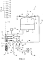
- filling unit 1 will be now described with reference to a contactless filling operation with a still product and with reference to only one filling device 10 and respective only one article 2, and to only one respective filling line 35, 44, 70 ( Figures 2 and 4 ).
- portion 8 of tank 6 is filled with a gas, i.e. carbon dioxide or nitrogen, while portion 7 of tank 6 is filled with the food product with which article 2 will be filled.
- a gas i.e. carbon dioxide or nitrogen
- Carousel 3 is fed with empty article 2 at inlet station I, advances it along path P along which article 2 is filled with the carbonated food product and discharges the filled article 2 at outlet station O.
- gripping device 17 rotates about axis A and grips neck 12 of article 2 and moves from the lowered position to raised position at station I, and from the raised position to the lowered position at station O.
- mouth 11 of article 2 is spaced along axis B from body 19 of filling device 10. Accordingly, openings 30 of ducts 18a, 18b, 18c and cavities 31 are in fluid contact with the environment surrounding filling device 10.
- Control unit 45 sets shutter 16 in the open configuration, and sets valves 41, 46 and 75 in the respective closed configurations.
- shutter 16 is spaced along axis B from protrusion 22 and the food product is free to pass through passage 24 and opening 21. The food product, then, fall for gravity inside empty article 2.
- control unit 45 sets shutter 16 in the closed configuration.
- control unit 45 controls valves 39, 41, so as to generate a continuous constant flow of gas through portion 8 of tank 6 and along portion 36 of fluidic line 35. That flow prevents contaminant agents from entering inside portion 7 of tank 6 and contaminating the food product.
- control unit 45 sets valve 42 in the respective open configuration.
- control unit 45 also sets valve 46 in the respective open configuration, in order to discharge the gas coming out from portion 8 of tank 6.
- fluidic lines 44 are distinct from fluidic lines 35 and discharge return gas in discharge 55 distinct from tank 6, in case of contact filling of article 2 with carbonated product.
- the return gas coming out for articles 2 is prevented from mixing with the gas coming out from portion 8 of tank 6 and intended to pressurize articles 2.
- fluidic lines 35, 44 are not physically isolated, but are connected by duct 60.
- duct 60 together with hydraulic losses along 56, 57 is effective in keeping a constant pressure difference between the higher first pressure value in pressure chamber 40 and the lower second pressure value in return chamber 48, regardless the punctual values of the first pressure and the second pressure values.
- the distributed hydraulic losses along duct 60 and segment 56 as well as the concentrated hydraulic losses 62, 63 substantially prevent, in case of contact filling, the gas present in chamber 40 to move towards chamber 48 and vice-versa.
- a preferential flow of gas intended to pressurize articles 2 is established from portion 8 of tank 6 to the inner volume of articles 2 during the pressurization of articles 2 and a preferential flow of return gas is established from the inner volume of articles 2 towards discharge 55 during the filling step, without any mixing between the two flows (as shown by the arrows in Figure 1 ).
- the continuous flow of gas through portion 8 of tank 6 is discharged, by suitably controlling valves 42, 46, in the area between opening 21 of body 19 and mouth 11 of article 2.
- the pressurization and/or de-pressurization step of article 2 could not be present, in case of contact filling of article 2 with carbonated products.
- control unit 45 can set valves 42 and/or valves 46 in the respective open configurations, either with respective shutters 16 in the respective closed configurations or with respective shutters 16 in the respective open configurations.
Landscapes
- Filling Of Jars Or Cans And Processes For Cleaning And Sealing Jars (AREA)
- Devices For Dispensing Beverages (AREA)
- Filling Or Discharging Of Gas Storage Vessels (AREA)
Claims (11)
- Unité de remplissage (1) pour un remplissage avec contact ou sans contact d'un article (2) avec un produit liquide, comprenant:- un réservoir (6) comprenant, tour à tour, une première région (7) remplissable avec ledit produit liquide et une seconde région (8) remplissable avec une première substance aériforme; et- au moins un dispositif de remplissage (10); ledit dispositif de remplissage (10) comprenant, tour à tour:- une première soupape (16), qui est placée, pendant l'utilisation, dans une première configuration ouverte dans laquelle elle permet la connexion fluidique entre ladite première région (7) dudit réservoir (6) et ledit article (2), de manière à remplir ledit article (2) avec ledit produit liquide, ou dans une première configuration fermée, dans laquelle elle empêche la connexion fluidique entre ladite première région (7) et ledit article (2);- une première ligne fluidique (35) pour ladite première substance aériforme, qui s'étend à partir de ladite seconde région (8) dudit réservoir (6) jusqu'à un volume intérieur dudit article (2) en cas de remplissage avec contact;- une deuxième soupape (42), qui est placée, pendant l'utilisation, dans une deuxième configuration ouverte, dans laquelle elle permet l'écoulement de ladite première substance aériforme le long de ladite première ligne fluidique (35), ou dans une deuxième configuration fermée, dans laquelle elle empêche ladite substance aériforme de s'écouler le long de ladite première ligne fluidique (35); et- une unité de commande (45) configurée de manière à placer ladite première soupape (16) dans ladite première configuration fermée et ladite deuxième soupape (42) dans ladite deuxième configuration ouverte en cas de remplissage avec contact, de manière à pressuriser ledit article (2) avant le remplissage de celui-ci avec ledit produit liquide; et- au moins une deuxième ligne fluidique (44) pour ladite première substance aériforme et/ou une seconde substance aériforme contenue(s) à l'intérieur dudit article (2), qui est distincte de ladite première ligne fluidique (35) et qui s'étend à partir dudit volume intérieur dudit article (2) jusqu'à une région de décharge (55) distincte dudit réservoir (6); et- au moins une troisième soupape (46) qui, pendant l'utilisation, est placée de façon sélective dans une troisième configuration ouverte dans laquelle elle permet l'écoulement de ladite première substance aériforme et/ou de ladite seconde substance aériforme le long de ladite deuxième ligne fluidique (44), ou dans une troisième configuration fermée dans laquelle elle empêche ladite première substance aériforme et/ou ladite seconde substance aériforme de s'écouler le long de ladite deuxième ligne fluidique (44);ladite unité de commande (45) étant configurée de manière à placer ladite première soupape (16) dans ladite première configuration ouverte et ladite troisième soupape (46) dans ladite troisième configuration ouverte en cas de remplissage avec contact, de manière à permettre à ladite première substance aériforme et/ou à une seconde substance aériforme contenue(s) dans ledit article (2) d'être déchargée(s) hors dudit article (2) pendant le remplissage avec contact dudit article (2);
ladite unité de remplissage (1) comprenant en outre:- une première chambre (40) intercalée le long de ladite première ligne fluidique (35); et- une seconde chambre (48) intercalée le long de ladite deuxième ligne fluidique (44) et distincte de ladite première chambre (40);l'unité de remplissage étant caractérisée en ce qu'elle comprend en outre un conduit (60), qui est interposé entre ladite première ligne fluidique (35) et ladite deuxième ligne fluidique (44) et qui est agencé à l'extérieur dudit dispositif de remplissage (10);
ledit conduit (60) étant apte à maintenir, pendant l'utilisation, une différence de pression donnée entre ladite première ligne fluidique (35) et ladite deuxième ligne fluidique (44);
ladite unité de remplissage comprenant en outre:- un point de connexion (61), auquel ladite deuxième ligne fluidique (44) et ledit conduit (60) sont connectés fluidiquement; ladite deuxième ligne fluidique (44) comprenant une partie (56) qui est intercalée entre ladite seconde chambre (48) et ledit point de connexion (61); et- un premier moyen pour créer une perte hydraulique (62), qui est agencé le long de ladite partie (56), et/ou- un second moyen pour créer une perte hydraulique (63), qui est agencé le long dudit conduit (60). - Unité de remplissage selon la revendication 1, caractérisée en ce que ladite première ligne fluidique (35) présente une sortie (18a, 30) qui est agencée à l'opposé dudit réservoir (6) et qui, pendant l'utilisation, est en connexion fluidique avec une ouverture de remplissage (21) dudit dispositif de remplissage (10); et en ce que ladite deuxième ligne fluidique (44) présente une entrée (18b, 30), qui est agencée sur le côté dudit dispositif de remplissage (10) et qui est en connexion fluidique avec ladite ouverture de remplissage (21);
ladite sortie et ladite entrée (18a, 30; 18b, 30) étant séparées l'une de l'autre. - Unité de remplissage selon l'une quelconque des revendications 1 ou 2, caractérisée en ce que ladite première chambre (40), pendant l'utilisation, est maintenue à une première valeur de pression qui est supérieure à une deuxième valeur de pression à laquelle ladite seconde chambre (48) est maintenue pendant l'utilisation;
ladite région de décharge (55) est maintenue pendant l'utilisation, à une troisième valeur de pression qui est inférieure à ladite deuxième valeur de pression, de telle sorte que ladite première substance aériforme et/ou ladite seconde substance aériforme s'écoule(nt) à partir de ladite seconde chambre (40) jusqu'à ladite région de décharge (55) et soi(en)t sensiblement empêchée(s) de s'écouler à partir de ladite seconde chambre (40) jusqu'à ladite première chambre (40). - Unité de remplissage selon l'une quelconque des revendications précédentes, caractérisée en ce qu'elle comprend:- au moins une troisième ligne fluidique (70), qui s'étend à partir d'une troisième entrée (18c; 30) jusqu'à une région de décharge supplémentaire (80), et qui est apte à permettre la décharge de ladite première substance aériforme et/ou de ladite seconde substance aériforme à partir dudit article (2) après l'accomplissement du remplissage avec contact de l'article (2): ladite troisième entrée (18c; 30) étant en connexion fluidique avec ladite ouverture (21) dudit dispositif de remplissage (10);- au moins une quatrième soupape (75), qui peut être placée dans une quatrième configuration ouverte, dans laquelle elle permet auxdites première et seconde substances aériformes de s'écouler le long de ladite troisième ligne fluidique (70), ou dans une quatrième configuration fermée, dans laquelle elle empêche lesdites première et seconde substances aériformes de s'écouler le long de ladite troisième ligne fluidique (70);ladite unité de commande (45) étant configurée de manière à maintenir ladite quatrième soupape (75) dans ladite quatrième configuration fermée et ladite première soupape (16) dans ladite première configuration ouverte pendant le remplissage avec contact dudit article (2), et pour placer ladite première soupape (16) dans ladite première configuration fermée et ladite quatrième soupape (75) dans ladite quatrième configuration ouverte de manière à dépressuriser ledit article (2) après l'accomplissement dudit remplissage avec contact dudit article (2).
- Unité de remplissage selon l'une quelconque des revendications précédentes, caractérisée en ce que ledit dispositif de remplissage (10) comprend:- un corps (19), qui définit une première ouverture (20) connectée fluidiquement à ladite première région (7) dudit réservoir (6), et une deuxième ouverture (21) opposée à ladite première ouverture (20);- un obturateur (16), qui est mobile entre une première position dans laquelle il est en contact avec ledit corps (19) de manière à isoler fluidiquement ladite première ouverture (20) de ladite deuxième ouverture (21), et une deuxième position dans laquelle il définit un passage (24) avec ledit corps (19) de manière à permettre le passage dudit produit alimentaire à partir dudit réservoir (6) jusqu'à ladite bouche de remplissage (11) à travers ladite deuxième ouverture (21);ledit corps (19) définissant eau moins:- un premier conduit (18a), qui fait partie de ladite première ligne fluidique (35) et qui est connecté fluidiquement à ladite deuxième ouverture (21); et- un deuxième conduit- un deuxième conduit (18b), qui fait partie de ladite deuxième ligne fluidique (44) et qui est connecté fluidiquement à ladite deuxième ouverture (21) ;ledit premier conduit et ledit deuxième conduit (18a, 18b) étant fluidiquement distincts l'un de l'autre;
lesdits premier et deuxième conduits (18a, 18b) étant radialement extérieurs audit obturateur (16) par rapport à un premier axe (B) dudit corps (19);
ledit premier corps (19) étant, pendant l'utilisation, coaxial audit article (2). - Unité de remplissage selon l'une quelconque des revendications précédentes, caractérisée en ce qu'elle comprend en outre des moyens de soupape supplémentaires (39, 41) aptes à commander l'écoulement de ladite première substance aériforme qui entre dans et sort de ladite seconde partie (8) dudit réservoir (6);
ladite unité de commande (45) étant configurée, en cas de remplissage sans contact dudit article (2), de manière à:- commander lesdits moyens de soupape supplémentaires (39, 41) de manière à établir un écoulement continu de ladite première substance aériforme à travers ladite seconde partie (8) dudit réservoir (7); et- placer ladite deuxième soupape (42) dans ladite deuxième configuration ouverte, de manière à décharger ladite première substance aériforme dans une région libre définie entre ladite deuxième ouverture (21) dudit dispositif de remplissage (10) et ledit article (2). - Unité de remplissage selon la revendication 6, caractérisée en ce que ladite unité de commande (45) est également configurée de manière à:- placer ladite troisième soupape (46) dans ladite troisième configuration ouverte, de manière à décharger au moins une partie de ladite seconde substance aériforme dans ladite région libre.
- Unité de remplissage selon l'une quelconque des revendications précédentes, caractérisée en ce qu'elle comprend un carrousel (3) rotatif autour d'un second axe (A) et comprenant une pluralité desdits dispositifs de remplissage (10); lesdites première et seconde chambres (40, 48) étant annulaires autour dudit axe (A).
- Procédé de remplissage avec contact ou sans contact d'un article (2) avec un produit liquide en utilisant une unité de remplissage (1) selon l'une quelconque des revendications 1 à 8, ledit procédé comprenant les étapes suivantes:a) placer ladite première soupape (16) dans ladite première configuration fermée; etb) placer ladite deuxième soupape (42) dans ladite deuxième configuration ouverte, en cas de remplissage avec contact, de manière à pressuriser ledit article (2), avant le remplissage de celui-ci;ledit procédé comprenant, en cas de remplissage avec contact, les étapes suivantes:c) placer une troisième soupape (46) dans une troisième configuration ouverte, dans laquelle elle permet l'écoulement de ladite première substance aériforme et/ou d'une seconde substance aériforme contenue (s) dans ledit article (2) le long d'une deuxième ligne fluidique (44), qui est distincte de ladite première ligne fluidique (35) et qui s'étend à partir dudit volume intérieur dudit article (2) jusqu'à une région de décharge (55) fluidiquement indépendante dudit réservoir (6), de manière à décharger ladite première substance aériforme et/ou une seconde substance aériforme contenue(s) dans ledit article (2);caractérisé en ce qu'il comprend les étapes suivantes:d) maintenir ladite première ligne fluidique (35) à une première valeur de pression;e) maintenir ladite deuxième ligne fluidique (44) à une deuxième valeur de pression, inférieure à ladite première valeur de pression et supérieure à une troisième valeur de pression de ladite région de décharge (55); etf) créer une différence constante entre ladite première valeur de pression et ladite deuxième valeur de pression, en intercalant un conduit (60) entre ladite première ligne fluidique (35) et une deuxième ligne fluidique (44).
- Procédé selon la revendication 9, caractérisé en ce qu'il comprend les étapes suivantes:g) placer une quatrième soupape (75) dans une quatrième configuration fermée, dans laquelle elle empêche ladite première substance aériforme ou ladite seconde substance aériforme de s'écouler le long d'une troisième ligne fluidique (70), pendant le remplissage avec contact dudit article;h) placer ladite première soupape (16) dans ladite première configuration fermée, après l'accomplissement dudit remplissage avec contact dudit article (2); eti) placer ladite quatrième soupape (75) dans une quatrième configuration ouverte, dans laquelle elle permet à ladite première substance aériforme ou à ladite seconde substance aériforme de s'écouler le long de ladite troisième ligne fluidique (70), de manière à dépressuriser ledit article (2).
- Procédé selon l'une quelconque des revendications 9 ou 10, caractérisé en ce qu'il comprend, en cas de remplissage sans contact, les étapes suivantes:j) établir un écoulement continu de ladite première substance aériforme à travers ladite seconde partie (8) dudit réservoir (6); etk) placer ladite deuxième soupape (41) dans ladite deuxième configuration ouverte, de manière à décharger ladite première substance aériforme dans l'environnement extérieur à travers une ouverture (21) dudit dispositif de remplissage (10).
Priority Applications (4)
| Application Number | Priority Date | Filing Date | Title |
|---|---|---|---|
| EP13192230.4A EP2871150B1 (fr) | 2013-11-08 | 2013-11-08 | Unité et procédé de remplissage d'un article avec un produit liquide |
| JP2014226872A JP6636693B2 (ja) | 2013-11-08 | 2014-11-07 | 注入可能な製品で物品を充填するための充填ユニットおよび方法 |
| US14/536,584 US9695028B2 (en) | 2013-11-08 | 2014-11-07 | Filling unit and method for filling an article with a pourable product |
| CN201410628936.9A CN104627926B (zh) | 2013-11-08 | 2014-11-10 | 用于向物品填充可倾倒的产品的填充单元及填充方法 |
Applications Claiming Priority (1)
| Application Number | Priority Date | Filing Date | Title |
|---|---|---|---|
| EP13192230.4A EP2871150B1 (fr) | 2013-11-08 | 2013-11-08 | Unité et procédé de remplissage d'un article avec un produit liquide |
Publications (2)
| Publication Number | Publication Date |
|---|---|
| EP2871150A1 EP2871150A1 (fr) | 2015-05-13 |
| EP2871150B1 true EP2871150B1 (fr) | 2017-02-01 |
Family
ID=49582565
Family Applications (1)
| Application Number | Title | Priority Date | Filing Date |
|---|---|---|---|
| EP13192230.4A Active EP2871150B1 (fr) | 2013-11-08 | 2013-11-08 | Unité et procédé de remplissage d'un article avec un produit liquide |
Country Status (4)
| Country | Link |
|---|---|
| US (1) | US9695028B2 (fr) |
| EP (1) | EP2871150B1 (fr) |
| JP (1) | JP6636693B2 (fr) |
| CN (1) | CN104627926B (fr) |
Families Citing this family (8)
| Publication number | Priority date | Publication date | Assignee | Title |
|---|---|---|---|---|
| EP3176126B1 (fr) * | 2015-12-04 | 2018-08-08 | Sidel Participations | Dispositif de remplissage pour une machine de remplissage |
| EP3202704B1 (fr) | 2016-02-08 | 2018-09-26 | Sidel Participations | Procédé pour détecter l'état défectueux d'un article à contact rempli d'un produit fluide et dispositif de remplissage |
| US11274023B2 (en) * | 2016-05-03 | 2022-03-15 | Codi Manufacturing, Inc. | Modulated pressure control of beverage fill flow |
| IT201600128045A1 (it) * | 2016-12-19 | 2018-06-19 | Weightpack Srl | Macchina riempitrice a peso netto con pompa volumetrica |
| EP3421411B1 (fr) * | 2017-06-30 | 2021-11-10 | Sidel Participations | Unité de remplissage d'un article avec un produit versable |
| DE102017120324A1 (de) * | 2017-09-04 | 2019-03-07 | Krones Ag | Vorrichtung und Verfahren zum Befüllen eines Behälters mit einem Füllprodukt |
| IT201800007011A1 (it) * | 2018-07-06 | 2020-01-06 | Dispositivo per test di tenuta in camera a vuoto e procedimento di realizzazione di detto test | |
| JP7457235B2 (ja) | 2020-02-18 | 2024-03-28 | 澁谷工業株式会社 | 充填装置 |
Citations (1)
| Publication number | Priority date | Publication date | Assignee | Title |
|---|---|---|---|---|
| EP1216952A2 (fr) * | 2000-12-23 | 2002-06-26 | KHS Maschinen- und Anlagenbau Aktiengesellschaft | Machine de remplissage |
Family Cites Families (23)
| Publication number | Priority date | Publication date | Assignee | Title |
|---|---|---|---|---|
| US3595281A (en) * | 1969-12-01 | 1971-07-27 | Herman Laub | Automatic container-filler valve |
| JPS57204892A (en) * | 1981-06-05 | 1982-12-15 | Mitsubishi Heavy Ind Ltd | Liquid filler with long filling pipe |
| JPS5937189A (ja) * | 1982-08-10 | 1984-02-29 | 三菱重工業株式会社 | 液充填装置 |
| JPH0825593B2 (ja) * | 1986-09-30 | 1996-03-13 | 三菱重工業株式会社 | 液体充填装置 |
| DE4342142C2 (de) * | 1993-12-10 | 2003-12-24 | Khs Masch & Anlagenbau Ag | Vorrichtung zum Füllen von Flaschen oder dergl. Behälter mit einem flüssigen Füllgut |
| DE10008426B4 (de) | 2000-02-23 | 2011-07-28 | KHS GmbH, 44143 | System sowie Verfahren zum Füllen von Behältern mit einem flüssigen Füllgut |
| JP2002211689A (ja) * | 2001-01-22 | 2002-07-31 | Mitsubishi Heavy Ind Ltd | 液体充填装置及び充填方法 |
| US6786248B2 (en) * | 2001-10-11 | 2004-09-07 | Fogg Filler Company | Fill valve assembly for filler device |
| JP2003237895A (ja) * | 2002-02-20 | 2003-08-27 | Toyo Jidoki Co Ltd | 液体充填ノズル及び液体充填装置 |
| ITBO20020735A1 (it) * | 2002-11-20 | 2004-05-21 | Marchesini Group Spa | Dispositivo valvolare idraulico multivia |
| DE10343281A1 (de) * | 2003-09-18 | 2005-04-21 | Adelholzener Alpenquellen Gmbh | Verfahren und Vorrichtung zur Herstellung und Abfüllung von mit Sauerstoff angereicherten Flüssigkeiten |
| DE102004015167B3 (de) * | 2004-03-27 | 2005-11-03 | Khs Maschinen- Und Anlagenbau Ag | Füllelement |
| DE102005011659A1 (de) * | 2005-03-08 | 2006-09-14 | Khs Ag | Betätigungselement sowie Füllmaschine mit derartigen Betätigungselementen |
| ITMO20050229A1 (it) * | 2005-09-12 | 2007-03-13 | Sig Simonazzi Spa | Apparato |
| ITBO20050599A1 (it) * | 2005-10-07 | 2007-04-08 | Sacmi Filling Spa | Rubinetto universale per l'imbottigliamento asettico di liquidi alimentari |
| US20070107801A1 (en) * | 2005-11-14 | 2007-05-17 | Sidel And Pressco Technology Inc. | Bottle filling machine with sensor and method thereof |
| JP2008050029A (ja) * | 2006-08-24 | 2008-03-06 | Shibuya Kogyo Co Ltd | 充填装置 |
| DE102008048738A1 (de) * | 2008-09-24 | 2010-03-25 | Krones Ag | Vorrichtung zur Überwachung einer Wasserdampfströmung |
| DE102009009339A1 (de) * | 2009-02-17 | 2010-08-26 | Khs Ag | Füllelement zum Füllen von Flaschen oder dergleichen Behältern sowie Füllmaschine mit derartigen Füllelementen |
| DE102011111483A1 (de) * | 2011-08-30 | 2013-02-28 | Khs Gmbh | Behälterbehandlungsmaschine |
| ITTO20110935A1 (it) * | 2011-10-18 | 2013-04-19 | Sidel Spa Con Socio Unico | Organo selettore di portata ad azionamento magnetico, organo regolatore di portata e macchina riempitrice |
| DE102011120372A1 (de) * | 2011-12-07 | 2013-06-13 | Khs Gmbh | Füllelement sowie Füllsystem |
| EP2889260B1 (fr) * | 2013-12-30 | 2016-03-09 | Sidel S.p.a. Con Socio Unico | Unité pour exécuter une opération sur un récipient pouvant être rempli avec un produit coulant |
-
2013
- 2013-11-08 EP EP13192230.4A patent/EP2871150B1/fr active Active
-
2014
- 2014-11-07 JP JP2014226872A patent/JP6636693B2/ja active Active
- 2014-11-07 US US14/536,584 patent/US9695028B2/en active Active
- 2014-11-10 CN CN201410628936.9A patent/CN104627926B/zh active Active
Patent Citations (1)
| Publication number | Priority date | Publication date | Assignee | Title |
|---|---|---|---|---|
| EP1216952A2 (fr) * | 2000-12-23 | 2002-06-26 | KHS Maschinen- und Anlagenbau Aktiengesellschaft | Machine de remplissage |
Also Published As
| Publication number | Publication date |
|---|---|
| CN104627926A (zh) | 2015-05-20 |
| US20150129083A1 (en) | 2015-05-14 |
| JP2015098361A (ja) | 2015-05-28 |
| EP2871150A1 (fr) | 2015-05-13 |
| JP6636693B2 (ja) | 2020-01-29 |
| CN104627926B (zh) | 2016-11-30 |
| US9695028B2 (en) | 2017-07-04 |
Similar Documents
| Publication | Publication Date | Title |
|---|---|---|
| EP2871150B1 (fr) | Unité et procédé de remplissage d'un article avec un produit liquide | |
| EP1995208B1 (fr) | Machine rotative de remplissage pour le remplissage de récipients avec du liquide | |
| CN106829836B (zh) | 用于填充机的填充装置 | |
| US9902603B2 (en) | Method and filling machine for filling cans or the like containers with liquid contents | |
| EP2903929B1 (fr) | Dispositif de remplissage pour machines de remplissage isobares pour le remplissage de bouteilles avec des liquides alimentaires et machine de remplissage isobare comprenant un tel dispositif | |
| US20170057801A1 (en) | Method and filling system for filling containers | |
| CN111533065A (zh) | 用于处理容器的装置 | |
| US10899592B2 (en) | Filling unit and method for filling an article with a pourable product | |
| EP3473590B1 (fr) | Dispositif de remplissage amélioré pour une machine de remplissage | |
| JP2008105699A (ja) | 充填バルブ | |
| US6520221B2 (en) | Filling nozzle with interception of supply liquids for filling machines | |
| EP2716592B1 (fr) | Dispositif de remplissage | |
| EP3473588A1 (fr) | Dispositif et procédé pour remplir des récipients avec un produit liquide sous pression | |
| EP3184484B1 (fr) | Dispositif de remplissage sélectif par contact ou sans contact d'un article avec un produit versable | |
| EP3473589A1 (fr) | Machine de remplissage et procédé de remplissage pour remplir des contenants avec un produit liquide sous pression | |
| EP2949617B1 (fr) | Unité et procédé de remplissage à contact ou sans contact d'un article avec un produit liquide | |
| EP3822224A1 (fr) | Machine de remplissage et procédé de remplissage de récipients avec un produit fluide | |
| EP2548838B1 (fr) | Dispositif pour remplir des récipients et procédé de lavage associé |
Legal Events
| Date | Code | Title | Description |
|---|---|---|---|
| PUAI | Public reference made under article 153(3) epc to a published international application that has entered the european phase |
Free format text: ORIGINAL CODE: 0009012 |
|
| 17P | Request for examination filed |
Effective date: 20131108 |
|
| AK | Designated contracting states |
Kind code of ref document: A1 Designated state(s): AL AT BE BG CH CY CZ DE DK EE ES FI FR GB GR HR HU IE IS IT LI LT LU LV MC MK MT NL NO PL PT RO RS SE SI SK SM TR |
|
| AX | Request for extension of the european patent |
Extension state: BA ME |
|
| R17P | Request for examination filed (corrected) |
Effective date: 20151112 |
|
| RBV | Designated contracting states (corrected) |
Designated state(s): AL AT BE BG CH CY CZ DE DK EE ES FI FR GB GR HR HU IE IS IT LI LT LU LV MC MK MT NL NO PL PT RO RS SE SI SK SM TR |
|
| 17Q | First examination report despatched |
Effective date: 20160208 |
|
| GRAP | Despatch of communication of intention to grant a patent |
Free format text: ORIGINAL CODE: EPIDOSNIGR1 |
|
| RIC1 | Information provided on ipc code assigned before grant |
Ipc: B67C 3/00 20060101ALI20160823BHEP Ipc: B67C 3/28 20060101AFI20160823BHEP |
|
| INTG | Intention to grant announced |
Effective date: 20160926 |
|
| GRAS | Grant fee paid |
Free format text: ORIGINAL CODE: EPIDOSNIGR3 |
|
| GRAA | (expected) grant |
Free format text: ORIGINAL CODE: 0009210 |
|
| AK | Designated contracting states |
Kind code of ref document: B1 Designated state(s): AL AT BE BG CH CY CZ DE DK EE ES FI FR GB GR HR HU IE IS IT LI LT LU LV MC MK MT NL NO PL PT RO RS SE SI SK SM TR |
|
| REG | Reference to a national code |
Ref country code: GB Ref legal event code: FG4D |
|
| REG | Reference to a national code |
Ref country code: CH Ref legal event code: EP Ref country code: AT Ref legal event code: REF Ref document number: 865404 Country of ref document: AT Kind code of ref document: T Effective date: 20170215 |
|
| REG | Reference to a national code |
Ref country code: IE Ref legal event code: FG4D |
|
| REG | Reference to a national code |
Ref country code: DE Ref legal event code: R096 Ref document number: 602013016950 Country of ref document: DE |
|
| REG | Reference to a national code |
Ref country code: NL Ref legal event code: MP Effective date: 20170201 |
|
| REG | Reference to a national code |
Ref country code: LT Ref legal event code: MG4D |
|
| REG | Reference to a national code |
Ref country code: AT Ref legal event code: MK05 Ref document number: 865404 Country of ref document: AT Kind code of ref document: T Effective date: 20170201 |
|
| PG25 | Lapsed in a contracting state [announced via postgrant information from national office to epo] |
Ref country code: NO Free format text: LAPSE BECAUSE OF FAILURE TO SUBMIT A TRANSLATION OF THE DESCRIPTION OR TO PAY THE FEE WITHIN THE PRESCRIBED TIME-LIMIT Effective date: 20170501 Ref country code: FI Free format text: LAPSE BECAUSE OF FAILURE TO SUBMIT A TRANSLATION OF THE DESCRIPTION OR TO PAY THE FEE WITHIN THE PRESCRIBED TIME-LIMIT Effective date: 20170201 Ref country code: LT Free format text: LAPSE BECAUSE OF FAILURE TO SUBMIT A TRANSLATION OF THE DESCRIPTION OR TO PAY THE FEE WITHIN THE PRESCRIBED TIME-LIMIT Effective date: 20170201 Ref country code: GR Free format text: LAPSE BECAUSE OF FAILURE TO SUBMIT A TRANSLATION OF THE DESCRIPTION OR TO PAY THE FEE WITHIN THE PRESCRIBED TIME-LIMIT Effective date: 20170502 Ref country code: HR Free format text: LAPSE BECAUSE OF FAILURE TO SUBMIT A TRANSLATION OF THE DESCRIPTION OR TO PAY THE FEE WITHIN THE PRESCRIBED TIME-LIMIT Effective date: 20170201 Ref country code: IS Free format text: LAPSE BECAUSE OF FAILURE TO SUBMIT A TRANSLATION OF THE DESCRIPTION OR TO PAY THE FEE WITHIN THE PRESCRIBED TIME-LIMIT Effective date: 20170601 |
|
| PG25 | Lapsed in a contracting state [announced via postgrant information from national office to epo] |
Ref country code: PL Free format text: LAPSE BECAUSE OF FAILURE TO SUBMIT A TRANSLATION OF THE DESCRIPTION OR TO PAY THE FEE WITHIN THE PRESCRIBED TIME-LIMIT Effective date: 20170201 Ref country code: NL Free format text: LAPSE BECAUSE OF FAILURE TO SUBMIT A TRANSLATION OF THE DESCRIPTION OR TO PAY THE FEE WITHIN THE PRESCRIBED TIME-LIMIT Effective date: 20170201 Ref country code: RS Free format text: LAPSE BECAUSE OF FAILURE TO SUBMIT A TRANSLATION OF THE DESCRIPTION OR TO PAY THE FEE WITHIN THE PRESCRIBED TIME-LIMIT Effective date: 20170201 Ref country code: PT Free format text: LAPSE BECAUSE OF FAILURE TO SUBMIT A TRANSLATION OF THE DESCRIPTION OR TO PAY THE FEE WITHIN THE PRESCRIBED TIME-LIMIT Effective date: 20170601 Ref country code: LV Free format text: LAPSE BECAUSE OF FAILURE TO SUBMIT A TRANSLATION OF THE DESCRIPTION OR TO PAY THE FEE WITHIN THE PRESCRIBED TIME-LIMIT Effective date: 20170201 Ref country code: ES Free format text: LAPSE BECAUSE OF FAILURE TO SUBMIT A TRANSLATION OF THE DESCRIPTION OR TO PAY THE FEE WITHIN THE PRESCRIBED TIME-LIMIT Effective date: 20170201 Ref country code: AT Free format text: LAPSE BECAUSE OF FAILURE TO SUBMIT A TRANSLATION OF THE DESCRIPTION OR TO PAY THE FEE WITHIN THE PRESCRIBED TIME-LIMIT Effective date: 20170201 Ref country code: BG Free format text: LAPSE BECAUSE OF FAILURE TO SUBMIT A TRANSLATION OF THE DESCRIPTION OR TO PAY THE FEE WITHIN THE PRESCRIBED TIME-LIMIT Effective date: 20170501 Ref country code: SE Free format text: LAPSE BECAUSE OF FAILURE TO SUBMIT A TRANSLATION OF THE DESCRIPTION OR TO PAY THE FEE WITHIN THE PRESCRIBED TIME-LIMIT Effective date: 20170201 |
|
| REG | Reference to a national code |
Ref country code: FR Ref legal event code: PLFP Year of fee payment: 5 |
|
| PG25 | Lapsed in a contracting state [announced via postgrant information from national office to epo] |
Ref country code: CZ Free format text: LAPSE BECAUSE OF FAILURE TO SUBMIT A TRANSLATION OF THE DESCRIPTION OR TO PAY THE FEE WITHIN THE PRESCRIBED TIME-LIMIT Effective date: 20170201 Ref country code: RO Free format text: LAPSE BECAUSE OF FAILURE TO SUBMIT A TRANSLATION OF THE DESCRIPTION OR TO PAY THE FEE WITHIN THE PRESCRIBED TIME-LIMIT Effective date: 20170201 Ref country code: EE Free format text: LAPSE BECAUSE OF FAILURE TO SUBMIT A TRANSLATION OF THE DESCRIPTION OR TO PAY THE FEE WITHIN THE PRESCRIBED TIME-LIMIT Effective date: 20170201 Ref country code: SK Free format text: LAPSE BECAUSE OF FAILURE TO SUBMIT A TRANSLATION OF THE DESCRIPTION OR TO PAY THE FEE WITHIN THE PRESCRIBED TIME-LIMIT Effective date: 20170201 |
|
| REG | Reference to a national code |
Ref country code: DE Ref legal event code: R097 Ref document number: 602013016950 Country of ref document: DE |
|
| PG25 | Lapsed in a contracting state [announced via postgrant information from national office to epo] |
Ref country code: SM Free format text: LAPSE BECAUSE OF FAILURE TO SUBMIT A TRANSLATION OF THE DESCRIPTION OR TO PAY THE FEE WITHIN THE PRESCRIBED TIME-LIMIT Effective date: 20170201 Ref country code: DK Free format text: LAPSE BECAUSE OF FAILURE TO SUBMIT A TRANSLATION OF THE DESCRIPTION OR TO PAY THE FEE WITHIN THE PRESCRIBED TIME-LIMIT Effective date: 20170201 |
|
| PLBE | No opposition filed within time limit |
Free format text: ORIGINAL CODE: 0009261 |
|
| STAA | Information on the status of an ep patent application or granted ep patent |
Free format text: STATUS: NO OPPOSITION FILED WITHIN TIME LIMIT |
|
| 26N | No opposition filed |
Effective date: 20171103 |
|
| PG25 | Lapsed in a contracting state [announced via postgrant information from national office to epo] |
Ref country code: SI Free format text: LAPSE BECAUSE OF FAILURE TO SUBMIT A TRANSLATION OF THE DESCRIPTION OR TO PAY THE FEE WITHIN THE PRESCRIBED TIME-LIMIT Effective date: 20170201 |
|
| PG25 | Lapsed in a contracting state [announced via postgrant information from national office to epo] |
Ref country code: MC Free format text: LAPSE BECAUSE OF FAILURE TO SUBMIT A TRANSLATION OF THE DESCRIPTION OR TO PAY THE FEE WITHIN THE PRESCRIBED TIME-LIMIT Effective date: 20170201 |
|
| GBPC | Gb: european patent ceased through non-payment of renewal fee |
Effective date: 20171108 |
|
| PG25 | Lapsed in a contracting state [announced via postgrant information from national office to epo] |
Ref country code: LI Free format text: LAPSE BECAUSE OF NON-PAYMENT OF DUE FEES Effective date: 20171130 Ref country code: CH Free format text: LAPSE BECAUSE OF NON-PAYMENT OF DUE FEES Effective date: 20171130 |
|
| PG25 | Lapsed in a contracting state [announced via postgrant information from national office to epo] |
Ref country code: LU Free format text: LAPSE BECAUSE OF NON-PAYMENT OF DUE FEES Effective date: 20171108 |
|
| REG | Reference to a national code |
Ref country code: BE Ref legal event code: MM Effective date: 20171130 |
|
| REG | Reference to a national code |
Ref country code: IE Ref legal event code: MM4A |
|
| PG25 | Lapsed in a contracting state [announced via postgrant information from national office to epo] |
Ref country code: MT Free format text: LAPSE BECAUSE OF NON-PAYMENT OF DUE FEES Effective date: 20171108 |
|
| REG | Reference to a national code |
Ref country code: FR Ref legal event code: PLFP Year of fee payment: 6 |
|
| PG25 | Lapsed in a contracting state [announced via postgrant information from national office to epo] |
Ref country code: IE Free format text: LAPSE BECAUSE OF NON-PAYMENT OF DUE FEES Effective date: 20171108 |
|
| PG25 | Lapsed in a contracting state [announced via postgrant information from national office to epo] |
Ref country code: GB Free format text: LAPSE BECAUSE OF NON-PAYMENT OF DUE FEES Effective date: 20171108 Ref country code: BE Free format text: LAPSE BECAUSE OF NON-PAYMENT OF DUE FEES Effective date: 20171130 |
|
| PG25 | Lapsed in a contracting state [announced via postgrant information from national office to epo] |
Ref country code: HU Free format text: LAPSE BECAUSE OF FAILURE TO SUBMIT A TRANSLATION OF THE DESCRIPTION OR TO PAY THE FEE WITHIN THE PRESCRIBED TIME-LIMIT; INVALID AB INITIO Effective date: 20131108 |
|
| PG25 | Lapsed in a contracting state [announced via postgrant information from national office to epo] |
Ref country code: CY Free format text: LAPSE BECAUSE OF FAILURE TO SUBMIT A TRANSLATION OF THE DESCRIPTION OR TO PAY THE FEE WITHIN THE PRESCRIBED TIME-LIMIT Effective date: 20170201 |
|
| PG25 | Lapsed in a contracting state [announced via postgrant information from national office to epo] |
Ref country code: MK Free format text: LAPSE BECAUSE OF FAILURE TO SUBMIT A TRANSLATION OF THE DESCRIPTION OR TO PAY THE FEE WITHIN THE PRESCRIBED TIME-LIMIT Effective date: 20170201 |
|
| PG25 | Lapsed in a contracting state [announced via postgrant information from national office to epo] |
Ref country code: TR Free format text: LAPSE BECAUSE OF FAILURE TO SUBMIT A TRANSLATION OF THE DESCRIPTION OR TO PAY THE FEE WITHIN THE PRESCRIBED TIME-LIMIT Effective date: 20170201 |
|
| PG25 | Lapsed in a contracting state [announced via postgrant information from national office to epo] |
Ref country code: AL Free format text: LAPSE BECAUSE OF FAILURE TO SUBMIT A TRANSLATION OF THE DESCRIPTION OR TO PAY THE FEE WITHIN THE PRESCRIBED TIME-LIMIT Effective date: 20170201 |
|
| P01 | Opt-out of the competence of the unified patent court (upc) registered |
Effective date: 20230306 |
|
| PGFP | Annual fee paid to national office [announced via postgrant information from national office to epo] |
Ref country code: IT Payment date: 20231019 Year of fee payment: 11 Ref country code: FR Payment date: 20231019 Year of fee payment: 11 Ref country code: DE Payment date: 20231019 Year of fee payment: 11 |