EP2869957B1 - Rotary cutting tool and reversible cutting insert therefor - Google Patents
Rotary cutting tool and reversible cutting insert therefor Download PDFInfo
- Publication number
- EP2869957B1 EP2869957B1 EP13735454.4A EP13735454A EP2869957B1 EP 2869957 B1 EP2869957 B1 EP 2869957B1 EP 13735454 A EP13735454 A EP 13735454A EP 2869957 B1 EP2869957 B1 EP 2869957B1
- Authority
- EP
- European Patent Office
- Prior art keywords
- corner
- cutting
- insert
- cutting insert
- median
- Prior art date
- Legal status (The legal status is an assumption and is not a legal conclusion. Google has not performed a legal analysis and makes no representation as to the accuracy of the status listed.)
- Active
Links
- 238000005520 cutting process Methods 0.000 title claims description 192
- 230000002441 reversible effect Effects 0.000 title claims description 11
- 238000003801 milling Methods 0.000 claims description 16
- 230000002093 peripheral effect Effects 0.000 claims description 15
- 238000003825 pressing Methods 0.000 description 2
- 208000010392 Bone Fractures Diseases 0.000 description 1
- 206010017076 Fracture Diseases 0.000 description 1
- 230000001154 acute effect Effects 0.000 description 1
- 230000004075 alteration Effects 0.000 description 1
- 230000001419 dependent effect Effects 0.000 description 1
- 230000001747 exhibiting effect Effects 0.000 description 1
- 238000005304 joining Methods 0.000 description 1
- 238000004519 manufacturing process Methods 0.000 description 1
- 229910052751 metal Inorganic materials 0.000 description 1
- 239000002184 metal Substances 0.000 description 1
- 238000012986 modification Methods 0.000 description 1
- 230000004048 modification Effects 0.000 description 1
- 230000001737 promoting effect Effects 0.000 description 1
- 230000000717 retained effect Effects 0.000 description 1
- 238000005245 sintering Methods 0.000 description 1
- UONOETXJSWQNOL-UHFFFAOYSA-N tungsten carbide Chemical compound [W+]#[C-] UONOETXJSWQNOL-UHFFFAOYSA-N 0.000 description 1
- 210000003462 vein Anatomy 0.000 description 1
Images


Classifications
-
- B—PERFORMING OPERATIONS; TRANSPORTING
- B23—MACHINE TOOLS; METAL-WORKING NOT OTHERWISE PROVIDED FOR
- B23B—TURNING; BORING
- B23B5/00—Turning-machines or devices specially adapted for particular work; Accessories specially adapted therefor
- B23B5/18—Turning-machines or devices specially adapted for particular work; Accessories specially adapted therefor for turning crankshafts, eccentrics, or cams, e.g. crankpin lathes
- B23B5/20—Turning-machines or devices specially adapted for particular work; Accessories specially adapted therefor for turning crankshafts, eccentrics, or cams, e.g. crankpin lathes without removing same from the engine
-
- B—PERFORMING OPERATIONS; TRANSPORTING
- B23—MACHINE TOOLS; METAL-WORKING NOT OTHERWISE PROVIDED FOR
- B23C—MILLING
- B23C5/00—Milling-cutters
- B23C5/02—Milling-cutters characterised by the shape of the cutter
- B23C5/06—Face-milling cutters, i.e. having only or primarily a substantially flat cutting surface
-
- B—PERFORMING OPERATIONS; TRANSPORTING
- B23—MACHINE TOOLS; METAL-WORKING NOT OTHERWISE PROVIDED FOR
- B23C—MILLING
- B23C5/00—Milling-cutters
- B23C5/16—Milling-cutters characterised by physical features other than shape
- B23C5/20—Milling-cutters characterised by physical features other than shape with removable cutter bits or teeth or cutting inserts
- B23C5/202—Plate-like cutting inserts with special form
-
- B—PERFORMING OPERATIONS; TRANSPORTING
- B23—MACHINE TOOLS; METAL-WORKING NOT OTHERWISE PROVIDED FOR
- B23B—TURNING; BORING
- B23B2200/00—Details of cutting inserts
- B23B2200/36—Other features of cutting inserts not covered by B23B2200/04 - B23B2200/32
- B23B2200/3681—Split inserts, i.e. comprising two or more sections roughly equal in size and having similar or dissimilar cutting geometries
-
- B—PERFORMING OPERATIONS; TRANSPORTING
- B23—MACHINE TOOLS; METAL-WORKING NOT OTHERWISE PROVIDED FOR
- B23C—MILLING
- B23C2200/00—Details of milling cutting inserts
- B23C2200/04—Overall shape
- B23C2200/0477—Triangular
-
- B—PERFORMING OPERATIONS; TRANSPORTING
- B23—MACHINE TOOLS; METAL-WORKING NOT OTHERWISE PROVIDED FOR
- B23C—MILLING
- B23C2200/00—Details of milling cutting inserts
- B23C2200/12—Side or flank surfaces
- B23C2200/123—Side or flank surfaces curved
-
- B—PERFORMING OPERATIONS; TRANSPORTING
- B23—MACHINE TOOLS; METAL-WORKING NOT OTHERWISE PROVIDED FOR
- B23C—MILLING
- B23C2200/00—Details of milling cutting inserts
- B23C2200/20—Top or side views of the cutting edge
- B23C2200/201—Details of the nose radius and immediately surrounding areas
-
- B—PERFORMING OPERATIONS; TRANSPORTING
- B23—MACHINE TOOLS; METAL-WORKING NOT OTHERWISE PROVIDED FOR
- B23C—MILLING
- B23C2200/00—Details of milling cutting inserts
- B23C2200/20—Top or side views of the cutting edge
- B23C2200/208—Wiper, i.e. an auxiliary cutting edge to improve surface finish
-
- B—PERFORMING OPERATIONS; TRANSPORTING
- B23—MACHINE TOOLS; METAL-WORKING NOT OTHERWISE PROVIDED FOR
- B23C—MILLING
- B23C2200/00—Details of milling cutting inserts
- B23C2200/28—Angles
- B23C2200/286—Positive cutting angles
-
- B—PERFORMING OPERATIONS; TRANSPORTING
- B23—MACHINE TOOLS; METAL-WORKING NOT OTHERWISE PROVIDED FOR
- B23C—MILLING
- B23C2200/00—Details of milling cutting inserts
- B23C2200/28—Angles
- B23C2200/287—Positive rake angles
-
- Y—GENERAL TAGGING OF NEW TECHNOLOGICAL DEVELOPMENTS; GENERAL TAGGING OF CROSS-SECTIONAL TECHNOLOGIES SPANNING OVER SEVERAL SECTIONS OF THE IPC; TECHNICAL SUBJECTS COVERED BY FORMER USPC CROSS-REFERENCE ART COLLECTIONS [XRACs] AND DIGESTS
- Y10—TECHNICAL SUBJECTS COVERED BY FORMER USPC
- Y10T—TECHNICAL SUBJECTS COVERED BY FORMER US CLASSIFICATION
- Y10T407/00—Cutters, for shaping
- Y10T407/19—Rotary cutting tool
- Y10T407/1906—Rotary cutting tool including holder [i.e., head] having seat for inserted tool
- Y10T407/1908—Face or end mill
- Y10T407/1924—Specified tool shape
-
- Y—GENERAL TAGGING OF NEW TECHNOLOGICAL DEVELOPMENTS; GENERAL TAGGING OF CROSS-SECTIONAL TECHNOLOGIES SPANNING OVER SEVERAL SECTIONS OF THE IPC; TECHNICAL SUBJECTS COVERED BY FORMER USPC CROSS-REFERENCE ART COLLECTIONS [XRACs] AND DIGESTS
- Y10—TECHNICAL SUBJECTS COVERED BY FORMER USPC
- Y10T—TECHNICAL SUBJECTS COVERED BY FORMER US CLASSIFICATION
- Y10T407/00—Cutters, for shaping
- Y10T407/23—Cutters, for shaping including tool having plural alternatively usable cutting edges
Definitions
- the present invention relates to cutting inserts according to the preamble of claim 1 and cutting tools for use in metal cutting processes, in general, and to rotary cutting tools having reversible cutting inserts for milling operations, in particular.
- reversible cutting inserts being removably secured in a cutting body.
- these cutting tools are configured to perform square shoulder milling operations.
- US 7,241,082 discloses a generally rectangular shaped double-sided indexable cutting insert having two major and two minor side surfaces connected to two opposing end surfaces, and a total of four major cutting edges. A primary 'reversed' relief surface adjacent each major cutting edge is inclined to a median plane of the cutting insert at an acute interior angle. The cutting insert is retained in the insert pocket of a milling cutter and configured to perform milling operations with a positive axial rake angle.
- US 7,455,483 discloses a trigon-shaped double-sided indexable cutting insert of 'negative' geometry having six edge surfaces connected to two opposing sides, and a total of six main cutting edges.
- the cutting insert is seated in the insert pocket of a milling tool and configured to cut perpendicular corners in a workpiece with a positive rake angle.
- US 7,604,441 discloses a square double-ended indexable cutting insert of 'negative' geometry having four side surfaces connected to two opposing end surfaces, and a total of eight primary cutting edges.
- the cutting insert is seated in the insert pocket of a milling cutter and configured to cut a true 90° shoulder in a workpiece with a positive axial rake angle.
- the depth of the shoulder is limited by the size of the insert and dependent on the length of the primary cutting edge.
- US 2010/202839 A1 discloses a cutting insert according to the preamble of claim 1.
- a reversible indexable cutting insert comprising the features defined in claim 1.
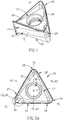
- the present invention relates to a reversible indexable cutting insert 20 having opposing first and second end surfaces 22 interconnected by a continuous peripheral surface 24, the peripheral surface 24 three side surfaces 26 alternating with three corner surfaces 28.
- the three side surfaces 26 may be identical, and the three corner surfaces 28 may be identical.
- the cutting insert 20 may have the basic shape of a regular polygon.
- the cutting insert 20 may preferably be manufactured by form pressing and sintering a cemented carbide, such as tungsten carbide, and may be coated or uncoated.
- the cutting insert 20 has a median plane M located between the first and second end surfaces 22 and intersecting the peripheral surface 24 to form an insert boundary line Lb.
- first and second end surfaces 22 may be identical, each having a support surface 30 substantially parallel to the median plane M.
- the two support surfaces 30 may be equidistant from the median plane M.
- the three side and corner surfaces 26, 28 may have side and corner median regions 32, 34, respectively, forming a continuous peripheral median region 36 extending perpendicular to the median plane M.
- the perpendicularity of the peripheral median region 36 with respect to the median plane M has a manufacturing tolerance of 0.5°.
- the peripheral median region 36 may exhibit mirror symmetry about the median plane M.
- each side median region 32 may be planar.
- the cutting insert 20 has an insert axis A1 perpendicular to the median plane M about which the cutting insert 20 is indexable.
- the peripheral surface 24 has exactly three side surfaces 26 alternating with exactly three corner surfaces 28, and the cutting insert 20 may exhibit three-fold rotational symmetry about the insert axis A1.
- a through bore 38 coaxial with the insert axis A1 may extend between and open out at both the first and second end surfaces 22.
- the cutting insert 20 may have the basic shape of an equilateral triangle.
- the cutting insert 20 may be manufactured by direct pressing along the direction of the insert axis A1 .
- the cutting insert 20 may be pressed into its final shape, and the peripheral surface 24 may be unground.
- the side and corner surfaces 26, 28 intersect with both the first and second end surfaces 22 at side and corner edges 40 , 42 , respectively, with each side edge 40 having a major cutting edge 44, and each corner edge 42 having a corner and minor cutting edge 46, 48.
- the cutting insert 20 is advantageously configured with two major cutting edges 44 per side surface 26, and two corner and minor cutting edges 46, 48 per corner surface 28, and thus for embodiments exhibiting three-fold rotational symmetry about the insert axis A1 , the cutting insert 20 has a total of six major, corner and minor cutting edges 44, 46, 48
- each corner cutting edge 46 may be curved while the minor and major cutting edges 44, 48 may be straight.
- Each curved corner cutting edge 46 extends between a first end point E1 , where it merges with a substantially straight portion of its associated major cutting edge 44, and a second end point E2, where it merges with substantially straight portion of its associated minor cutting edge 48.
- each corner cutting edge 46 may again be curved while the minor and major cutting edges 44, 48 may again be straight.
- a side axis A2 may extend transversely to each side surface 26, and each side surface 26 may exhibit two-fold rotational symmetry about its associated side axis A2.
- each major cutting edge 44 may intersect a side bisector plane Ps containing the insert axis A1 and its associated side axis A2. For these embodiments, it can be understood that each major cutting edge 44 extends along greater than half the peripheral length of its associated side surface 26.
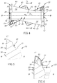
- each major and minor cutting edge 44, 48 slopes away from the first and second end points E1 , E2, respectively, of its mutually associated corner cutting edge 46, towards the median plane M.
- each major and minor cutting edge 44, 48 may slope away from its mutually associated corner cutting edge 46 towards the median plane M along its entire length.
- each corner cutting edge 46 may be entirely located further from the median plane M than each of the support surfaces 30 .
- each end surface 22 may include a rake surface 50 adjacent each major cutting edge 44 , with each rake surface 50 inclined towards the median plane M and merging with its associated support surface 30 .
- a first imaginary straight line L1 extending perpendicular to the median plane M and intersecting any one of the corner cutting edges 46 at any point along its length except the second end point E2, passes through the median plane M inside the insert boundary line Lb.
- the first imaginary straight line L1 appears as a point in an end view of the cutting insert 20 , as shown in Fig. 2b .
- each minor cutting edge 48 may be coincident with the insert boundary line Lb.
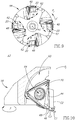
- each corner surface 28 may include two partially conical shaped corner relief surfaces 52 extending from the same corner median region 34 in opposite axial directions to their respective corner cutting edges 46. As seen in the corner side view of Fig. 3 , the two partially conical shaped corner relief surfaces 52 may overlap in the axial direction of the cutting insert 20 .
- each partially conical shaped corner relief surface 52 also known as a 'reversed' relief surface, generally extends inwardly (i.e., in a direction of the insert axis A1 ) from its associated corner median region 34 towards its respective corner cutting edge 46, so that each corner cutting edge 46 is beneficially supported and advantageously robust.
- each corner surface 28 may include two planar minor relief surfaces 54 extending from the same corner median region 34 in opposite axial directions to their respective minor cutting edges 48. As seen in the corner side view of Fig. 3 , the two planar minor relief surfaces 54 may not overlap in the axial direction of the cutting insert 20 .
- each minor relief surface 54 may be perpendicular to the median plane M.
- each minor relief surface 54 may be spaced apart from its adjacent side surface 26 by a non-planar joining surface 68.
- each corner surface 28 has a corner bisector plane Pc containing the insert axis A1 .
- each corner cutting edge 46 may intersect its associated corner bisector plane Pc, and its first and second end points E1 , E2 may be located on opposite sides of the corner bisector plane Pc.
- the corner bisector plane Pc may not pass through the highest point of the corner cutting edge 46.
- the corner bisector plane Pc may not bisect the corner cutting edge 46 (i.e., need not pass mid-way between its first and second end points E1 , E2 .)
- each corner median region 34 may exhibit mirror symmetry about its associated corner bisector plane Pc.
- each side median region 32 may form a first bisector angle ⁇ 1 with the corner bisector plane Pc of an adjacent corner surface 28, having a value of 30°.
- each minor relief surface 54 may form a second bisector angle ⁇ 2 with its associated corner bisector plane Pc, having a value of between 60° and 80°.
- a second imaginary straight line L2 extending perpendicular to the median plane M and intersecting any one of the major cutting edges 44 at any point along its length, may pass through the median plane M inside the insert boundary line Lb.
- each side surface 26 may include two major relief surfaces 56 extending from the same side median region 32 to their respective major cutting edges 44.
- each major cutting edge 44 may be substantially straight along its entire length, and each major relief surface 56 may be substantially planar.
- each major relief surface 56 also known as a 'reversed' relief surface, generally extends inwardly (i.e., in a direction of the insert axis A1 ) from its associated side median region 32 towards its respective major cutting edge 44, so that each major cutting edge 44 is beneficially supported and advantageously robust.
- the present invention also relates to a cutting tool 58 rotatable about a tool axis A3, in a direction of rotation Z, having a cutting body 60 and at least one of the aforementioned reversible indexable cutting inserts 20 .
- Each cutting insert 20 is removably secured in an insert receiving pocket 62 of the cutting body 60.
- each cutting insert 20 may be removably secured in the insert receiving pocket 62 by means of a clamping screw 64 passing through its through bore 38, and threadingly engaging a screw bore (not shown) in a seating surface (not shown) of the insert receiving pocket 62.
- each cutting insert 20 may be configured within the cutting tool 58 so that during rotation of the cutting tool 58 about its tool axis A3, the operative corner cutting edge 46 inscribes an arc-shaped first contour line C1 in a radial plane Pr containing the tool axis A3, with the first contour line C1 having a constant radius of curvature R subtending a corner cutting angle ⁇ of 90°.
- each cutting insert 20 may be configured within the cutting tool 58 so that during rotation of the cutting tool 58 about its tool axis A3, the operative major and minor cutting edges 44, 48 inscribe straight second and third contour lines C2, C3, respectively, in the radial plane Pr, with the second contour line C2 substantially parallel to the tool axis A3 and the third contour line C3 substantially perpendicular to the tool axis A3.
- the rotary cutting tool 58 may be used for milling operations.
- the operative corner cutting edge 46 cuts a corner in a workpiece (not shown) having a constant radius of curvature R subtending a corner cutting angle ⁇ of 90°, advantageously resulting in reduced stress concentrations at the corner, and thus minimizing its risk of fracture.
- the operative minor cutting edge 48 which can also be referred to as a wiper, is parallel to the surface of the workpiece, promoting an even and smooth surface finish.
- the major 'reversed' relief surfaces 56 beneficially provide the trailing non-operative major cutting edges 44 of each reversible cutting insert 20 with greater clearance from the workpiece, thus advantageously enabling their arrangement on relatively smaller diameter cutting tools 58.
- each cutting insert 20 may be configured within the cutting tool 58, so that the operative major, corner and minor cutting edges 44, 46, 48 perform a square, or 90°, shoulder milling operation in the workpiece.
- the height of the machined shoulder is not limited by the cutting insert 20 .
- each cutting insert 20 may be configured within the cutting tool 58, so that the operative major cutting edge 44 has a positive axial rake angle ⁇ , and the operative minor cutting edge 48 has a positive radial rake angle ⁇ .
- each side edge 40 may include an auxiliary cutting edge 66 extending from its associated major cutting edge 44 towards an adjacent minor cutting edge 48 belonging to an adjacent corner edge 42.
- Each cutting insert 20 may be configured within the cutting tool 58, so that the auxiliary cutting edge 66 adjacent the operative minor cutting edge 48 is operative during ramping operations.
- Each cutting insert 20 may also be configured within the cutting tool 58, so that the auxiliary cutting edge 66 extending from the operative major cutting edge 44 is operative during shoulder milling operations, thus increasing the insert's depth of cut.
- the auxiliary cutting edge 66 may be sloped to a lesser extent than its associated major cutting edge 44. In some embodiments, the auxiliary cutting edge 66 may be parallel to the median plane M.
- each auxiliary cutting edge 66 may be substantially coplanar with its associated support surface 30 .
- each end surface 22 may include an auxiliary rake groove (not shown) longitudinally extending adjacent each auxiliary cutting edge 66 to provide efficient chip evacuation during ramping operations.
Priority Applications (1)
| Application Number | Priority Date | Filing Date | Title |
|---|---|---|---|
| PL13735454T PL2869957T3 (pl) | 2012-07-06 | 2013-06-09 | Obrotowe narzędzie skrawające i odwracalna wkładka skrawająca dla niego |
Applications Claiming Priority (2)
| Application Number | Priority Date | Filing Date | Title |
|---|---|---|---|
| US13/542,846 US8708616B2 (en) | 2012-07-06 | 2012-07-06 | Rotary cutting tool and reversible cutting insert therefor |
| PCT/IL2013/050492 WO2014006609A1 (en) | 2012-07-06 | 2013-06-09 | Rotary cutting tool and reversible cutting insert therefor |
Publications (2)
| Publication Number | Publication Date |
|---|---|
| EP2869957A1 EP2869957A1 (en) | 2015-05-13 |
| EP2869957B1 true EP2869957B1 (en) | 2020-08-05 |
Family
ID=48782568
Family Applications (1)
| Application Number | Title | Priority Date | Filing Date |
|---|---|---|---|
| EP13735454.4A Active EP2869957B1 (en) | 2012-07-06 | 2013-06-09 | Rotary cutting tool and reversible cutting insert therefor |
Country Status (14)
| Country | Link |
|---|---|
| US (1) | US8708616B2 (pt) |
| EP (1) | EP2869957B1 (pt) |
| JP (1) | JP6277185B2 (pt) |
| KR (1) | KR101887254B1 (pt) |
| CN (1) | CN104395024B (pt) |
| BR (1) | BR112014033023B1 (pt) |
| CA (1) | CA2877602C (pt) |
| DE (1) | DE112013003461T5 (pt) |
| ES (1) | ES2813955T3 (pt) |
| IL (1) | IL236299B (pt) |
| PL (1) | PL2869957T3 (pt) |
| PT (1) | PT2869957T (pt) |
| RU (1) | RU2648717C2 (pt) |
| WO (1) | WO2014006609A1 (pt) |
Families Citing this family (45)
| Publication number | Priority date | Publication date | Assignee | Title |
|---|---|---|---|---|
| RU2012146970A (ru) * | 2010-05-06 | 2014-06-20 | Тунгалой Корпорейшн | Режущая пластина и режущий инструмент с заменяемой режущей пластиной |
| WO2013065393A1 (ja) * | 2011-10-31 | 2013-05-10 | 京セラ株式会社 | 切削インサートおよび切削工具、並びにそれを用いた切削加工物の製造方法 |
| EP2740555B1 (en) * | 2012-12-07 | 2016-03-16 | Sandvik Tooling France | Cutting tool for face milling, corresponding method of face milling, cutting insert and tool body |
| JP6205726B2 (ja) * | 2013-01-15 | 2017-10-04 | 三菱マテリアル株式会社 | 正面フライス用切削インサート及び刃先交換式正面フライス |
| JP5991563B2 (ja) * | 2013-12-25 | 2016-09-14 | 株式会社タンガロイ | 刃先交換式回転切削工具及び工具ボデー |
| USD746346S1 (en) * | 2013-12-27 | 2015-12-29 | Taegutec Ltd. | Cutting insert |
| USD746347S1 (en) * | 2013-12-27 | 2015-12-29 | Taegutec Ltd. | Cutting insert |
| AT14072U1 (de) * | 2014-02-04 | 2015-04-15 | Ceratizit Luxembourg S R L | Doppelseitiger Frässchneideinsatz und Fräswerkzeug |
| USD744557S1 (en) * | 2014-05-12 | 2015-12-01 | Sumitomo Electric Hardmetal Corp. | Cutting insert |
| CN106413958B (zh) | 2014-05-26 | 2018-12-04 | 株式会社泰珂洛 | 切削刀片、主体及切削刀具 |
| JP5888656B2 (ja) * | 2014-06-02 | 2016-03-22 | 住友電工ハードメタル株式会社 | 切削インサートとフライスカッタ |
| JP6449581B2 (ja) * | 2014-07-30 | 2019-01-09 | 京セラ株式会社 | 切削インサートおよびスローアウェイ式カッタ |
| US9468983B2 (en) * | 2014-09-22 | 2016-10-18 | Iscar, Ltd. | Rotary cutting tool and reversible cutting insert having variable-width minor relief surfaces therefor |
| EP2998053B1 (en) | 2014-09-22 | 2022-02-23 | Iscar Ltd. | Rotary cutting tool and reversible cutting insert having variable-width minor relief surfaces therefor |
| EP3072616B1 (en) * | 2015-03-25 | 2018-10-10 | Sandvik Intellectual Property AB | Cutting insert and milling tool |
| US10239125B2 (en) * | 2015-05-26 | 2019-03-26 | Kyocera Corporation | Cutting insert, cutting tool, and method for manufacturing machined product using same |
| USD777230S1 (en) | 2015-07-16 | 2017-01-24 | Kennametal Inc | Double-sided tangential cutting insert |
| US9981323B2 (en) | 2015-07-16 | 2018-05-29 | Kennametal Inc. | Double-sided tangential cutting insert and cutting tool system using the same |
| USD778330S1 (en) | 2015-07-16 | 2017-02-07 | Kennametal Inc. | Double-sided tangential cutting insert |
| EP3153260B1 (en) * | 2015-10-09 | 2018-05-23 | Sandvik Intellectual Property AB | Turning insert and method |
| JP6361948B2 (ja) * | 2015-10-19 | 2018-07-25 | 株式会社タンガロイ | 切削インサートおよび切削工具 |
| US10076795B2 (en) * | 2015-11-19 | 2018-09-18 | Iscar, Ltd. | Triangular tangential milling insert and milling tool |
| US10035199B2 (en) * | 2016-06-30 | 2018-07-31 | Iscar, Ltd. | Cutting tool and triangular-shaped indexable cutting insert therefor |
| DE112017003488T5 (de) * | 2016-07-11 | 2019-04-25 | Kyocera Corporation | Schneideinsatz, Schneidwerkzeug und Verfahren des Herstellens eines maschinell-bearbeiteten Produkts |
| EP3338931A4 (en) * | 2016-09-27 | 2019-09-11 | Tungaloy Corporation | CUTTING INSERT AND CUTTING TOOL |
| US10875105B2 (en) * | 2016-10-14 | 2020-12-29 | Sumitomo Electric Hardmetal Corp. | Cutting insert |
| EP3315234A1 (en) | 2016-10-25 | 2018-05-02 | Pramet Tools, S.R.O. | Metal cutting insert for milling |
| EP3338927B1 (en) * | 2016-12-22 | 2023-07-26 | Sandvik Intellectual Property AB | Cutting insert and shoulder milling tool |
| EP3338928B1 (en) * | 2016-12-22 | 2022-03-30 | Sandvik Intellectual Property AB | Cutting insert and shoulder milling tool |
| CN106735487B (zh) * | 2016-12-28 | 2018-07-13 | 株洲华锐硬质合金工具有限责任公司 | 铣削加工用可转位刀片及加工刀具 |
| EP3616814A4 (en) * | 2017-04-25 | 2021-01-20 | Sumitomo Electric Hardmetal Corp. | CUTTING INSERT |
| CN107295907A (zh) * | 2017-06-07 | 2017-10-27 | 江苏鼎钰生态农业科技有限公司 | 一种电动修枝机中的刀片 |
| TWI825040B (zh) * | 2017-11-30 | 2023-12-11 | 以色列商艾斯卡公司 | 單側三向可轉位銑削嵌件、刀具固持器及包括嵌件及刀具固持器的嵌件式銑刀 |
| TWI787381B (zh) * | 2017-11-30 | 2022-12-21 | 以色列商艾斯卡公司 | 單側三向可轉位切削嵌件及其嵌件式銑刀 |
| EP3542936A1 (en) * | 2018-03-22 | 2019-09-25 | AB Sandvik Coromant | A cutting insert for a shoulder milling tool |
| EP3556498B1 (en) * | 2018-04-16 | 2021-02-17 | Seco Tools Ab | Cutting insert and milling tool |
| WO2019235084A1 (ja) | 2018-06-08 | 2019-12-12 | 三菱日立ツール株式会社 | 切削インサートおよび刃先交換式切削工具 |
| EP3845338A4 (en) * | 2018-08-30 | 2022-06-08 | Mitsubishi Materials Corporation | CUTTING INSERT AND CUTTING TOOL OF CUTTING EDGE REPLACEMENT TYPE |
| WO2020085245A1 (ja) * | 2018-10-23 | 2020-04-30 | 京セラ株式会社 | 切削インサート、切削工具及び切削加工物の製造方法 |
| JP6744599B1 (ja) * | 2019-03-01 | 2020-08-19 | 株式会社タンガロイ | 切削インサート |
| DE102020115987A1 (de) * | 2019-07-05 | 2021-01-07 | Kennametal India Limited | Beidseitige, polygonale wendeschneidplatte mit abwechselnd konkaven und konvexen schneidkanten |
| AT16933U1 (de) * | 2019-07-11 | 2020-12-15 | Ceratizit Austria Gmbh | Doppelseitiger Schneideinsatz zum Fräsen |
| DE102019123912A1 (de) | 2019-09-05 | 2021-03-11 | Kennametal Inc. | Schneideinsatz sowie Schneidwerkzeug |
| WO2021193705A1 (ja) * | 2020-03-25 | 2021-09-30 | 京セラ株式会社 | 回転工具及び切削加工物の製造方法 |
| JP7011689B1 (ja) * | 2020-08-11 | 2022-01-27 | 株式会社タンガロイ | 切削インサート及び回転切削工具 |
Family Cites Families (20)
| Publication number | Priority date | Publication date | Assignee | Title |
|---|---|---|---|---|
| US4318644A (en) * | 1980-07-07 | 1982-03-09 | Gte Products Corporation | Cutting insert |
| US4359300A (en) * | 1980-12-29 | 1982-11-16 | General Electric Co. | Cutting insert with improved chip control |
| US4411565A (en) * | 1981-05-08 | 1983-10-25 | General Electric Company | Finishing insert with improved chip control |
| US4618296A (en) * | 1983-09-14 | 1986-10-21 | Gte Valeron Corporation | Cutting tool and insert therefor |
| SU1505683A1 (ru) * | 1987-06-04 | 1989-09-07 | Предприятие П/Я Г-4760 | Сборный режущий инструмент |
| SE520997C2 (sv) * | 2001-01-09 | 2003-09-23 | Sandvik Ab | Vändbart frässkär med rillförsedd kopplingsyta mot hållaren och centralt materialparti för fästorgan |
| IL160223A (en) * | 2004-02-04 | 2008-11-26 | Carol Smilovici | Double-sided cutting insert and milling cutter |
| IL169491A (en) | 2005-06-30 | 2009-06-15 | Carol Smilovici | Cutting insert |
| SE529068C2 (sv) | 2005-09-28 | 2007-04-24 | Seco Tools Ab | Frässkär och fräsverktyg |
| IL182100A (en) * | 2007-03-21 | 2010-11-30 | Taegutec India Ltd | Cutting insert for a milling cutter |
| PL2139633T3 (pl) * | 2007-04-26 | 2017-09-29 | Taegu Tec India P.Ltd. | Wkładka skrawająca do frezu |
| DE102008001898A1 (de) * | 2007-05-24 | 2008-11-27 | Ceramtec Ag | Schneidplatte mit stabilisierender doppelseitiger Facette |
| US8491234B2 (en) * | 2009-02-12 | 2013-07-23 | TDY Industries, LLC | Double-sided cutting inserts for high feed milling |
| US7976250B2 (en) * | 2009-02-12 | 2011-07-12 | Tdy Industries, Inc. | Double-sided cutting inserts for high feed milling |
| DE102009020373A1 (de) * | 2009-05-08 | 2010-11-11 | Kennametal Inc. | Fräser-Schneideinsatz |
| KR101097658B1 (ko) * | 2009-05-29 | 2011-12-22 | 대구텍 유한회사 | 절삭 삽입체 |
| KR100939085B1 (ko) | 2009-07-15 | 2010-01-28 | 한국야금 주식회사 | 절삭 인서트 |
| EP2394766A1 (en) * | 2010-06-10 | 2011-12-14 | Lamina Technologies SA | Double-sided indexable cutting insert and cutting tool |
| DE102011105978B4 (de) | 2011-06-29 | 2022-06-23 | Kennametal Inc. | Wendeschneidplatte sowie Plan-Eckfräser mit Wendeschneidplatte |
| US8573905B2 (en) * | 2012-03-22 | 2013-11-05 | Iscar, Ltd. | Triangular cutting insert and cutting tool |
-
2012
- 2012-07-06 US US13/542,846 patent/US8708616B2/en active Active
-
2013
- 2013-06-09 ES ES13735454T patent/ES2813955T3/es active Active
- 2013-06-09 DE DE112013003461.1T patent/DE112013003461T5/de not_active Withdrawn
- 2013-06-09 EP EP13735454.4A patent/EP2869957B1/en active Active
- 2013-06-09 RU RU2015103929A patent/RU2648717C2/ru active
- 2013-06-09 KR KR1020147036904A patent/KR101887254B1/ko active IP Right Grant
- 2013-06-09 JP JP2015519485A patent/JP6277185B2/ja active Active
- 2013-06-09 WO PCT/IL2013/050492 patent/WO2014006609A1/en active Application Filing
- 2013-06-09 CA CA2877602A patent/CA2877602C/en active Active
- 2013-06-09 BR BR112014033023-9A patent/BR112014033023B1/pt active IP Right Grant
- 2013-06-09 PT PT137354544T patent/PT2869957T/pt unknown
- 2013-06-09 PL PL13735454T patent/PL2869957T3/pl unknown
- 2013-06-09 CN CN201380035823.1A patent/CN104395024B/zh active Active
-
2014
- 2014-12-16 IL IL236299A patent/IL236299B/en active IP Right Grant
Non-Patent Citations (1)
| Title |
|---|
| None * |
Also Published As
| Publication number | Publication date |
|---|---|
| PL2869957T3 (pl) | 2021-01-11 |
| RU2648717C2 (ru) | 2018-03-28 |
| KR20150030217A (ko) | 2015-03-19 |
| CN104395024A (zh) | 2015-03-04 |
| JP6277185B2 (ja) | 2018-02-07 |
| ES2813955T3 (es) | 2021-03-25 |
| KR101887254B1 (ko) | 2018-08-09 |
| JP2015521958A (ja) | 2015-08-03 |
| WO2014006609A1 (en) | 2014-01-09 |
| EP2869957A1 (en) | 2015-05-13 |
| BR112014033023A2 (pt) | 2017-06-27 |
| DE112013003461T5 (de) | 2015-03-26 |
| US20140010605A1 (en) | 2014-01-09 |
| CA2877602A1 (en) | 2014-01-09 |
| IL236299B (en) | 2018-01-31 |
| CA2877602C (en) | 2018-02-13 |
| IL236299A0 (en) | 2015-02-26 |
| PT2869957T (pt) | 2020-10-07 |
| CN104395024B (zh) | 2017-09-12 |
| BR112014033023B1 (pt) | 2020-09-15 |
| US8708616B2 (en) | 2014-04-29 |
| RU2015103929A (ru) | 2016-08-27 |
Similar Documents
| Publication | Publication Date | Title |
|---|---|---|
| EP2869957B1 (en) | Rotary cutting tool and reversible cutting insert therefor | |
| CA2959774C (en) | Rotary cutting tool and reversible cutting insert having variable-width minor relief surfaces therefor | |
| EP2998053B1 (en) | Rotary cutting tool and reversible cutting insert having variable-width minor relief surfaces therefor | |
| US8449230B2 (en) | Cutting insert having concave clearance depressions formed on corner side surfaces | |
| EP3150317B1 (en) | Cutting insert and milling cutter | |
| EP3199283B1 (en) | Cutting insert and replaceable-edge rotary cutting tool | |
| US9475135B2 (en) | Milling insert | |
| EP2214857B1 (en) | Tangential cutting insert | |
| WO2010035831A1 (ja) | 切削インサート、切削工具、およびそれらを用いる切削方法 | |
| EP3266547B1 (en) | Cutting insert and cutting edge-replaceable rotary cutting tool | |
| JP2018534159A (ja) | 旋削インサートおよび方法 | |
| WO2016147493A1 (ja) | 切削インサート、切削インサート群および刃先交換式切削工具 | |
| CN104785835A (zh) | 一种具有精加工和粗加工切削刃的切削刀片 | |
| KR102554780B1 (ko) | 곡선의 이차 절삭 에지와 코너 절삭 에지를 가진 정사각형 형태의 절삭 인서트 및 회전 절삭 공구 | |
| KR20190034266A (ko) | 절삭 인서트 및 날끝 교환식 회전 절삭 공구 | |
| WO2017068922A1 (ja) | 切削インサートおよび切削工具 | |
| US20220118533A1 (en) | Reversible square-shaped cutting insert and rotary cutting tool | |
| CN208450680U (zh) | 用于加工石墨工件的铣刀 | |
| CN208450681U (zh) | 用于加工石墨工件的铣刀 | |
| JP2009184086A (ja) | スローアウェイチップ |
Legal Events
| Date | Code | Title | Description |
|---|---|---|---|
| PUAI | Public reference made under article 153(3) epc to a published international application that has entered the european phase |
Free format text: ORIGINAL CODE: 0009012 |
|
| 17P | Request for examination filed |
Effective date: 20150103 |
|
| AK | Designated contracting states |
Kind code of ref document: A1 Designated state(s): AL AT BE BG CH CY CZ DE DK EE ES FI FR GB GR HR HU IE IS IT LI LT LU LV MC MK MT NL NO PL PT RO RS SE SI SK SM TR |
|
| AX | Request for extension of the european patent |
Extension state: BA ME |
|
| DAX | Request for extension of the european patent (deleted) | ||
| STAA | Information on the status of an ep patent application or granted ep patent |
Free format text: STATUS: EXAMINATION IS IN PROGRESS |
|
| 17Q | First examination report despatched |
Effective date: 20180613 |
|
| GRAP | Despatch of communication of intention to grant a patent |
Free format text: ORIGINAL CODE: EPIDOSNIGR1 |
|
| STAA | Information on the status of an ep patent application or granted ep patent |
Free format text: STATUS: GRANT OF PATENT IS INTENDED |
|
| INTG | Intention to grant announced |
Effective date: 20200110 |
|
| GRAJ | Information related to disapproval of communication of intention to grant by the applicant or resumption of examination proceedings by the epo deleted |
Free format text: ORIGINAL CODE: EPIDOSDIGR1 |
|
| STAA | Information on the status of an ep patent application or granted ep patent |
Free format text: STATUS: EXAMINATION IS IN PROGRESS |
|
| INTC | Intention to grant announced (deleted) | ||
| GRAS | Grant fee paid |
Free format text: ORIGINAL CODE: EPIDOSNIGR3 |
|
| STAA | Information on the status of an ep patent application or granted ep patent |
Free format text: STATUS: GRANT OF PATENT IS INTENDED |
|
| GRAP | Despatch of communication of intention to grant a patent |
Free format text: ORIGINAL CODE: EPIDOSNIGR1 |
|
| INTG | Intention to grant announced |
Effective date: 20200525 |
|
| GRAA | (expected) grant |
Free format text: ORIGINAL CODE: 0009210 |
|
| STAA | Information on the status of an ep patent application or granted ep patent |
Free format text: STATUS: THE PATENT HAS BEEN GRANTED |
|
| AK | Designated contracting states |
Kind code of ref document: B1 Designated state(s): AL AT BE BG CH CY CZ DE DK EE ES FI FR GB GR HR HU IE IS IT LI LT LU LV MC MK MT NL NO PL PT RO RS SE SI SK SM TR |
|
| REG | Reference to a national code |
Ref country code: GB Ref legal event code: FG4D |
|
| REG | Reference to a national code |
Ref country code: CH Ref legal event code: EP |
|
| REG | Reference to a national code |
Ref country code: AT Ref legal event code: REF Ref document number: 1298014 Country of ref document: AT Kind code of ref document: T Effective date: 20200815 |
|
| REG | Reference to a national code |
Ref country code: DE Ref legal event code: R096 Ref document number: 602013071308 Country of ref document: DE |
|
| REG | Reference to a national code |
Ref country code: IE Ref legal event code: FG4D |
|
| REG | Reference to a national code |
Ref country code: SE Ref legal event code: TRGR |
|
| REG | Reference to a national code |
Ref country code: PT Ref legal event code: SC4A Ref document number: 2869957 Country of ref document: PT Date of ref document: 20201007 Kind code of ref document: T Free format text: AVAILABILITY OF NATIONAL TRANSLATION Effective date: 20200928 |
|
| REG | Reference to a national code |
Ref country code: LT Ref legal event code: MG4D |
|
| REG | Reference to a national code |
Ref country code: NL Ref legal event code: MP Effective date: 20200805 |
|
| PG25 | Lapsed in a contracting state [announced via postgrant information from national office to epo] |
Ref country code: FI Free format text: LAPSE BECAUSE OF FAILURE TO SUBMIT A TRANSLATION OF THE DESCRIPTION OR TO PAY THE FEE WITHIN THE PRESCRIBED TIME-LIMIT Effective date: 20200805 Ref country code: LT Free format text: LAPSE BECAUSE OF FAILURE TO SUBMIT A TRANSLATION OF THE DESCRIPTION OR TO PAY THE FEE WITHIN THE PRESCRIBED TIME-LIMIT Effective date: 20200805 Ref country code: BG Free format text: LAPSE BECAUSE OF FAILURE TO SUBMIT A TRANSLATION OF THE DESCRIPTION OR TO PAY THE FEE WITHIN THE PRESCRIBED TIME-LIMIT Effective date: 20201105 Ref country code: NO Free format text: LAPSE BECAUSE OF FAILURE TO SUBMIT A TRANSLATION OF THE DESCRIPTION OR TO PAY THE FEE WITHIN THE PRESCRIBED TIME-LIMIT Effective date: 20201105 Ref country code: GR Free format text: LAPSE BECAUSE OF FAILURE TO SUBMIT A TRANSLATION OF THE DESCRIPTION OR TO PAY THE FEE WITHIN THE PRESCRIBED TIME-LIMIT Effective date: 20201106 Ref country code: HR Free format text: LAPSE BECAUSE OF FAILURE TO SUBMIT A TRANSLATION OF THE DESCRIPTION OR TO PAY THE FEE WITHIN THE PRESCRIBED TIME-LIMIT Effective date: 20200805 |
|
| PG25 | Lapsed in a contracting state [announced via postgrant information from national office to epo] |
Ref country code: RS Free format text: LAPSE BECAUSE OF FAILURE TO SUBMIT A TRANSLATION OF THE DESCRIPTION OR TO PAY THE FEE WITHIN THE PRESCRIBED TIME-LIMIT Effective date: 20200805 Ref country code: LV Free format text: LAPSE BECAUSE OF FAILURE TO SUBMIT A TRANSLATION OF THE DESCRIPTION OR TO PAY THE FEE WITHIN THE PRESCRIBED TIME-LIMIT Effective date: 20200805 Ref country code: NL Free format text: LAPSE BECAUSE OF FAILURE TO SUBMIT A TRANSLATION OF THE DESCRIPTION OR TO PAY THE FEE WITHIN THE PRESCRIBED TIME-LIMIT Effective date: 20200805 Ref country code: IS Free format text: LAPSE BECAUSE OF FAILURE TO SUBMIT A TRANSLATION OF THE DESCRIPTION OR TO PAY THE FEE WITHIN THE PRESCRIBED TIME-LIMIT Effective date: 20201205 |
|
| REG | Reference to a national code |
Ref country code: ES Ref legal event code: FG2A Ref document number: 2813955 Country of ref document: ES Kind code of ref document: T3 Effective date: 20210325 |
|
| PG25 | Lapsed in a contracting state [announced via postgrant information from national office to epo] |
Ref country code: RO Free format text: LAPSE BECAUSE OF FAILURE TO SUBMIT A TRANSLATION OF THE DESCRIPTION OR TO PAY THE FEE WITHIN THE PRESCRIBED TIME-LIMIT Effective date: 20200805 Ref country code: SM Free format text: LAPSE BECAUSE OF FAILURE TO SUBMIT A TRANSLATION OF THE DESCRIPTION OR TO PAY THE FEE WITHIN THE PRESCRIBED TIME-LIMIT Effective date: 20200805 Ref country code: EE Free format text: LAPSE BECAUSE OF FAILURE TO SUBMIT A TRANSLATION OF THE DESCRIPTION OR TO PAY THE FEE WITHIN THE PRESCRIBED TIME-LIMIT Effective date: 20200805 Ref country code: DK Free format text: LAPSE BECAUSE OF FAILURE TO SUBMIT A TRANSLATION OF THE DESCRIPTION OR TO PAY THE FEE WITHIN THE PRESCRIBED TIME-LIMIT Effective date: 20200805 |
|
| REG | Reference to a national code |
Ref country code: DE Ref legal event code: R097 Ref document number: 602013071308 Country of ref document: DE |
|
| REG | Reference to a national code |
Ref country code: AT Ref legal event code: UEP Ref document number: 1298014 Country of ref document: AT Kind code of ref document: T Effective date: 20200805 |
|
| PG25 | Lapsed in a contracting state [announced via postgrant information from national office to epo] |
Ref country code: AL Free format text: LAPSE BECAUSE OF FAILURE TO SUBMIT A TRANSLATION OF THE DESCRIPTION OR TO PAY THE FEE WITHIN THE PRESCRIBED TIME-LIMIT Effective date: 20200805 |
|
| PLBE | No opposition filed within time limit |
Free format text: ORIGINAL CODE: 0009261 |
|
| STAA | Information on the status of an ep patent application or granted ep patent |
Free format text: STATUS: NO OPPOSITION FILED WITHIN TIME LIMIT |
|
| PG25 | Lapsed in a contracting state [announced via postgrant information from national office to epo] |
Ref country code: SK Free format text: LAPSE BECAUSE OF FAILURE TO SUBMIT A TRANSLATION OF THE DESCRIPTION OR TO PAY THE FEE WITHIN THE PRESCRIBED TIME-LIMIT Effective date: 20200805 |
|
| 26N | No opposition filed |
Effective date: 20210507 |
|
| PG25 | Lapsed in a contracting state [announced via postgrant information from national office to epo] |
Ref country code: SI Free format text: LAPSE BECAUSE OF FAILURE TO SUBMIT A TRANSLATION OF THE DESCRIPTION OR TO PAY THE FEE WITHIN THE PRESCRIBED TIME-LIMIT Effective date: 20200805 |
|
| PG25 | Lapsed in a contracting state [announced via postgrant information from national office to epo] |
Ref country code: MC Free format text: LAPSE BECAUSE OF FAILURE TO SUBMIT A TRANSLATION OF THE DESCRIPTION OR TO PAY THE FEE WITHIN THE PRESCRIBED TIME-LIMIT Effective date: 20200805 |
|
| REG | Reference to a national code |
Ref country code: CH Ref legal event code: PL |
|
| REG | Reference to a national code |
Ref country code: BE Ref legal event code: MM Effective date: 20210630 |
|
| PG25 | Lapsed in a contracting state [announced via postgrant information from national office to epo] |
Ref country code: LU Free format text: LAPSE BECAUSE OF NON-PAYMENT OF DUE FEES Effective date: 20210609 |
|
| PG25 | Lapsed in a contracting state [announced via postgrant information from national office to epo] |
Ref country code: LI Free format text: LAPSE BECAUSE OF NON-PAYMENT OF DUE FEES Effective date: 20210630 Ref country code: IE Free format text: LAPSE BECAUSE OF NON-PAYMENT OF DUE FEES Effective date: 20210609 Ref country code: CH Free format text: LAPSE BECAUSE OF NON-PAYMENT OF DUE FEES Effective date: 20210630 |
|
| PG25 | Lapsed in a contracting state [announced via postgrant information from national office to epo] |
Ref country code: BE Free format text: LAPSE BECAUSE OF NON-PAYMENT OF DUE FEES Effective date: 20210630 |
|
| PG25 | Lapsed in a contracting state [announced via postgrant information from national office to epo] |
Ref country code: HU Free format text: LAPSE BECAUSE OF FAILURE TO SUBMIT A TRANSLATION OF THE DESCRIPTION OR TO PAY THE FEE WITHIN THE PRESCRIBED TIME-LIMIT; INVALID AB INITIO Effective date: 20130609 |
|
| P01 | Opt-out of the competence of the unified patent court (upc) registered |
Effective date: 20230426 |
|
| PG25 | Lapsed in a contracting state [announced via postgrant information from national office to epo] |
Ref country code: CY Free format text: LAPSE BECAUSE OF FAILURE TO SUBMIT A TRANSLATION OF THE DESCRIPTION OR TO PAY THE FEE WITHIN THE PRESCRIBED TIME-LIMIT Effective date: 20200805 |
|
| PGFP | Annual fee paid to national office [announced via postgrant information from national office to epo] |
Ref country code: PT Payment date: 20230518 Year of fee payment: 11 Ref country code: IT Payment date: 20230426 Year of fee payment: 11 Ref country code: FR Payment date: 20230522 Year of fee payment: 11 Ref country code: DE Payment date: 20230508 Year of fee payment: 11 Ref country code: CZ Payment date: 20230602 Year of fee payment: 11 |
|
| PGFP | Annual fee paid to national office [announced via postgrant information from national office to epo] |
Ref country code: TR Payment date: 20230505 Year of fee payment: 11 Ref country code: SE Payment date: 20230505 Year of fee payment: 11 Ref country code: PL Payment date: 20230420 Year of fee payment: 11 Ref country code: AT Payment date: 20230508 Year of fee payment: 11 |
|
| PGFP | Annual fee paid to national office [announced via postgrant information from national office to epo] |
Ref country code: GB Payment date: 20230519 Year of fee payment: 11 Ref country code: ES Payment date: 20230807 Year of fee payment: 11 |
|
| PG25 | Lapsed in a contracting state [announced via postgrant information from national office to epo] |
Ref country code: MK Free format text: LAPSE BECAUSE OF FAILURE TO SUBMIT A TRANSLATION OF THE DESCRIPTION OR TO PAY THE FEE WITHIN THE PRESCRIBED TIME-LIMIT Effective date: 20200805 |