EP2869912B1 - Schlauchmatte und verfahren zum herstellen einer derartigen schlauchmatte - Google Patents
Schlauchmatte und verfahren zum herstellen einer derartigen schlauchmatte Download PDFInfo
- Publication number
- EP2869912B1 EP2869912B1 EP13730511.6A EP13730511A EP2869912B1 EP 2869912 B1 EP2869912 B1 EP 2869912B1 EP 13730511 A EP13730511 A EP 13730511A EP 2869912 B1 EP2869912 B1 EP 2869912B1
- Authority
- EP
- European Patent Office
- Prior art keywords
- tube
- mat
- tubular
- hose
- spacers
- Prior art date
- Legal status (The legal status is an assumption and is not a legal conclusion. Google has not performed a legal analysis and makes no representation as to the accuracy of the status listed.)
- Active
Links
Images


Classifications
-
- B—PERFORMING OPERATIONS; TRANSPORTING
- B29—WORKING OF PLASTICS; WORKING OF SUBSTANCES IN A PLASTIC STATE IN GENERAL
- B29C—SHAPING OR JOINING OF PLASTICS; SHAPING OF MATERIAL IN A PLASTIC STATE, NOT OTHERWISE PROVIDED FOR; AFTER-TREATMENT OF THE SHAPED PRODUCTS, e.g. REPAIRING
- B29C48/00—Extrusion moulding, i.e. expressing the moulding material through a die or nozzle which imparts the desired form; Apparatus therefor
- B29C48/03—Extrusion moulding, i.e. expressing the moulding material through a die or nozzle which imparts the desired form; Apparatus therefor characterised by the shape of the extruded material at extrusion
- B29C48/09—Articles with cross-sections having partially or fully enclosed cavities, e.g. pipes or channels
- B29C48/11—Articles with cross-sections having partially or fully enclosed cavities, e.g. pipes or channels comprising two or more partially or fully enclosed cavities, e.g. honeycomb-shaped
-
- A—HUMAN NECESSITIES
- A61—MEDICAL OR VETERINARY SCIENCE; HYGIENE
- A61M—DEVICES FOR INTRODUCING MEDIA INTO, OR ONTO, THE BODY; DEVICES FOR TRANSDUCING BODY MEDIA OR FOR TAKING MEDIA FROM THE BODY; DEVICES FOR PRODUCING OR ENDING SLEEP OR STUPOR
- A61M1/00—Suction or pumping devices for medical purposes; Devices for carrying-off, for treatment of, or for carrying-over, body-liquids; Drainage systems
- A61M1/14—Dialysis systems; Artificial kidneys; Blood oxygenators ; Reciprocating systems for treatment of body fluids, e.g. single needle systems for hemofiltration or pheresis
- A61M1/16—Dialysis systems; Artificial kidneys; Blood oxygenators ; Reciprocating systems for treatment of body fluids, e.g. single needle systems for hemofiltration or pheresis with membranes
- A61M1/1621—Constructional aspects thereof
- A61M1/1623—Disposition or location of membranes relative to fluids
- A61M1/1627—Dialyser of the inside perfusion type, i.e. blood flow inside hollow membrane fibres or tubes
-
- A—HUMAN NECESSITIES
- A61—MEDICAL OR VETERINARY SCIENCE; HYGIENE
- A61M—DEVICES FOR INTRODUCING MEDIA INTO, OR ONTO, THE BODY; DEVICES FOR TRANSDUCING BODY MEDIA OR FOR TAKING MEDIA FROM THE BODY; DEVICES FOR PRODUCING OR ENDING SLEEP OR STUPOR
- A61M1/00—Suction or pumping devices for medical purposes; Devices for carrying-off, for treatment of, or for carrying-over, body-liquids; Drainage systems
- A61M1/14—Dialysis systems; Artificial kidneys; Blood oxygenators ; Reciprocating systems for treatment of body fluids, e.g. single needle systems for hemofiltration or pheresis
- A61M1/16—Dialysis systems; Artificial kidneys; Blood oxygenators ; Reciprocating systems for treatment of body fluids, e.g. single needle systems for hemofiltration or pheresis with membranes
- A61M1/1621—Constructional aspects thereof
- A61M1/1629—Constructional aspects thereof with integral heat exchanger
-
- A—HUMAN NECESSITIES
- A61—MEDICAL OR VETERINARY SCIENCE; HYGIENE
- A61M—DEVICES FOR INTRODUCING MEDIA INTO, OR ONTO, THE BODY; DEVICES FOR TRANSDUCING BODY MEDIA OR FOR TAKING MEDIA FROM THE BODY; DEVICES FOR PRODUCING OR ENDING SLEEP OR STUPOR
- A61M1/00—Suction or pumping devices for medical purposes; Devices for carrying-off, for treatment of, or for carrying-over, body-liquids; Drainage systems
- A61M1/14—Dialysis systems; Artificial kidneys; Blood oxygenators ; Reciprocating systems for treatment of body fluids, e.g. single needle systems for hemofiltration or pheresis
- A61M1/16—Dialysis systems; Artificial kidneys; Blood oxygenators ; Reciprocating systems for treatment of body fluids, e.g. single needle systems for hemofiltration or pheresis with membranes
- A61M1/1698—Blood oxygenators with or without heat-exchangers
-
- B—PERFORMING OPERATIONS; TRANSPORTING
- B01—PHYSICAL OR CHEMICAL PROCESSES OR APPARATUS IN GENERAL
- B01D—SEPARATION
- B01D69/00—Semi-permeable membranes for separation processes or apparatus characterised by their form, structure or properties; Manufacturing processes specially adapted therefor
- B01D69/08—Hollow fibre membranes
-
- B—PERFORMING OPERATIONS; TRANSPORTING
- B29—WORKING OF PLASTICS; WORKING OF SUBSTANCES IN A PLASTIC STATE IN GENERAL
- B29C—SHAPING OR JOINING OF PLASTICS; SHAPING OF MATERIAL IN A PLASTIC STATE, NOT OTHERWISE PROVIDED FOR; AFTER-TREATMENT OF THE SHAPED PRODUCTS, e.g. REPAIRING
- B29C48/00—Extrusion moulding, i.e. expressing the moulding material through a die or nozzle which imparts the desired form; Apparatus therefor
- B29C48/25—Component parts, details or accessories; Auxiliary operations
- B29C48/30—Extrusion nozzles or dies
- B29C48/32—Extrusion nozzles or dies with annular openings, e.g. for forming tubular articles
-
- B—PERFORMING OPERATIONS; TRANSPORTING
- B29—WORKING OF PLASTICS; WORKING OF SUBSTANCES IN A PLASTIC STATE IN GENERAL
- B29D—PRODUCING PARTICULAR ARTICLES FROM PLASTICS OR FROM SUBSTANCES IN A PLASTIC STATE
- B29D99/00—Subject matter not provided for in other groups of this subclass
- B29D99/005—Producing membranes
-
- B—PERFORMING OPERATIONS; TRANSPORTING
- B29—WORKING OF PLASTICS; WORKING OF SUBSTANCES IN A PLASTIC STATE IN GENERAL
- B29K—INDEXING SCHEME ASSOCIATED WITH SUBCLASSES B29B, B29C OR B29D, RELATING TO MOULDING MATERIALS OR TO MATERIALS FOR MOULDS, REINFORCEMENTS, FILLERS OR PREFORMED PARTS, e.g. INSERTS
- B29K2075/00—Use of PU, i.e. polyureas or polyurethanes or derivatives thereof, as moulding material
-
- B—PERFORMING OPERATIONS; TRANSPORTING
- B29—WORKING OF PLASTICS; WORKING OF SUBSTANCES IN A PLASTIC STATE IN GENERAL
- B29K—INDEXING SCHEME ASSOCIATED WITH SUBCLASSES B29B, B29C OR B29D, RELATING TO MOULDING MATERIALS OR TO MATERIALS FOR MOULDS, REINFORCEMENTS, FILLERS OR PREFORMED PARTS, e.g. INSERTS
- B29K2883/00—Use of polymers having silicon, with or without sulfur, nitrogen, oxygen, or carbon only, in the main chain, as mould material
- B29K2883/005—LSR, i.e. liquid silicone rubbers, or derivatives thereof
-
- Y—GENERAL TAGGING OF NEW TECHNOLOGICAL DEVELOPMENTS; GENERAL TAGGING OF CROSS-SECTIONAL TECHNOLOGIES SPANNING OVER SEVERAL SECTIONS OF THE IPC; TECHNICAL SUBJECTS COVERED BY FORMER USPC CROSS-REFERENCE ART COLLECTIONS [XRACs] AND DIGESTS
- Y10—TECHNICAL SUBJECTS COVERED BY FORMER USPC
- Y10T—TECHNICAL SUBJECTS COVERED BY FORMER US CLASSIFICATION
- Y10T428/00—Stock material or miscellaneous articles
- Y10T428/24—Structurally defined web or sheet [e.g., overall dimension, etc.]
- Y10T428/24273—Structurally defined web or sheet [e.g., overall dimension, etc.] including aperture
-
- Y—GENERAL TAGGING OF NEW TECHNOLOGICAL DEVELOPMENTS; GENERAL TAGGING OF CROSS-SECTIONAL TECHNOLOGIES SPANNING OVER SEVERAL SECTIONS OF THE IPC; TECHNICAL SUBJECTS COVERED BY FORMER USPC CROSS-REFERENCE ART COLLECTIONS [XRACs] AND DIGESTS
- Y10—TECHNICAL SUBJECTS COVERED BY FORMER USPC
- Y10T—TECHNICAL SUBJECTS COVERED BY FORMER US CLASSIFICATION
- Y10T428/00—Stock material or miscellaneous articles
- Y10T428/24—Structurally defined web or sheet [e.g., overall dimension, etc.]
- Y10T428/24479—Structurally defined web or sheet [e.g., overall dimension, etc.] including variation in thickness
-
- Y—GENERAL TAGGING OF NEW TECHNOLOGICAL DEVELOPMENTS; GENERAL TAGGING OF CROSS-SECTIONAL TECHNOLOGIES SPANNING OVER SEVERAL SECTIONS OF THE IPC; TECHNICAL SUBJECTS COVERED BY FORMER USPC CROSS-REFERENCE ART COLLECTIONS [XRACs] AND DIGESTS
- Y10—TECHNICAL SUBJECTS COVERED BY FORMER USPC
- Y10T—TECHNICAL SUBJECTS COVERED BY FORMER US CLASSIFICATION
- Y10T428/00—Stock material or miscellaneous articles
- Y10T428/24—Structurally defined web or sheet [e.g., overall dimension, etc.]
- Y10T428/24744—Longitudinal or transverse tubular cavity or cell
Definitions
- the invention relates to a tubular mat, a method for producing such a tubular mat and a tool for extruding such a tubular mat.
- the hose assembly has four parallel running hose lines, which lie at the corners of a rhombus.
- the hose assembly is not a hose mat.
- the DE 35 87 787 T2 discloses a process for producing hollow fibers by melt spinning. For this purpose, specially designed spinnerets are required. Hollow fibers made of plastic are wetted with a spinning liquid. Such a process is complex.
- Hoses are known, which may have reinforcing elements such as ribs for stability reasons.
- a method of manufacturing a hose is known.
- a hose mat is out of the DE 43 04 246 A1 not known.
- the DE 27 04 678 A1 discloses a method for extruding a plastic net.
- ECC extracorporeal Circulation
- ECMO extracorporeal membrane oxygenation
- Such a hollow fiber bundle is from the DE 10 2010 000 820 A1 known.
- Several tube sections are arranged with their tube longitudinal axes parallel to each other and forfeited together in a direction perpendicular to the tube longitudinal axes by means of at least one effective seam.
- the WO 2012/040 778 A1 discloses a solar collector for heating and conveying liquids.
- the solar collector has a hose mat, the individual hoses are connected via a manifold.
- the tubular mat according to the invention is produced in one piece. In particular, it is not necessary to manufacture a plurality of tube sections individually, to arrange them in a mutually defined manner and subsequently forfeit each other.
- Hose sections automatically arranged defined to each other and connected together.
- the tube sections with their tube longitudinal axes are each arranged parallel to one another.
- the tube sections are each connected by a web section.
- the production of the tubular mat according to the invention is simplified. In particular, the number of process steps is reduced. The number of items is reduced, so that the assembly costs for the hose mat is eliminated. The assembly costs for the production of a heat exchanger as a whole is thereby reduced.
- the tubular mat can be produced in one piece by extrusion.
- the risk of contamination in the manufacture of the tubular mat is minimized, since in particular a Verwirk with knitting threads and thus an introduction of dust and / or fiber abrasion is excluded.
- the tubular mat has an increased reliability with regard to its application.
- the reject rate in the manufacture of the tubular mat is reduced.
- the risk that an unnoticed contamination of the tubular mat leads to a health risk for a patient is reduced.
- Such tubular mats can be used both in an extracorporeal circulation oxygenator (ECC) and in extracorporeal membrane oxygenation (ECMO).
- the tubular mat is basically also suitable for use in the pharmaceutical industry for so-called bioreactors.
- fermenters are known in which a bacterial culture is supplied in solution by hollow fibers with oxygen. Such hollow fibers can be imaged through the tubular mat.
- oxygenating fibers in tissue engineering, tissue engineering.
- the tubular mats can also be used as heat exchanger mats, for example in underfloor heating, wall heating and / or corresponding cooling elements are used.
- the tubular mat according to the invention is designed substantially flat as a mat in an output arrangement. This means that the longitudinal axes of the tube sections can be arranged in a mat plane. It is possible to roll up the tubular mat individually or with at least one further tubular mat to form a tube mat bundle, so that in particular a substantially cylindrical tube mat bundle results.
- a tubular mat having at least one spacer having a thickness oriented perpendicular to a mat plane which is larger than an outside diameter of a tube section enables a simplified manufacture of a tube bundle from a plurality of tube mats.
- the tube sections of a tubular mat can be arranged at a defined distance from each other.
- several tubular mats are rolled up or wound up into a tube bundle.
- a hose mat according to claim 2 allows a flexible connection of the hose mats to a hose mat bundle.
- a tubular mat according to one of claims 3 or 4 allows a connection of individual tubular mats together with an increased strength. Individual spacers can intervene in particular in corresponding spaces of another hose mat in the connection of the individual tubular mats with each other. The material used for the production of the spacers along the tube longitudinal axis with respect to a continuous, web-shaped spacer is reduced.
- a tubular mat according to claim 5 has an increased area moment of inertia with respect to a bending around a direction transverse to the tube longitudinal axis direction.
- the hose mat is stable.
- the spacers are designed as continuous webs. Such webs are easier to produce.
- a hose mat according to claim 6 allows an improved connection with another hose mat to a hose mat bundle.
- a hose mat according to claim 7 enables material savings in the production.
- such a tubular mat has an increased diffusion surface.
- a hose mat according to claim 8 can be produced in a simplified manner.
- the preparation of the hose mat is reliable feasible.
- Such a tubular mat is particularly suitable for use in an oxygenator module in the ECC.
- the tube mat can also be used for heat exchangers in general.
- a tool is initially provided with which a tubular mat can be extruded along an extrusion direction. Subsequently, the tubular mat is extruded, which has a plurality of tube sections arranged along the extrusion direction and at least one bar section connecting at least one tube section.
- Such a method is economical. Due to the fact that a plurality of tube sections are connected to one another by the web sections, a tube mat with improved structural stability results. In particular, the tubular mat can be better removed from the extrusion tool.
- a tubular mat produced in this way can be deposited and / or wound better.
- a plurality of tubular mats can be connected to form a tube bundle, in particular by arranging a tube section of a first tube mat on a web section of a second tube mat and then connecting these to a tube bundle by rolling.
- Such a tool is used to extrude a tubular mat along an extrusion direction.
- the tool has an extrusion die, which is connectable to an extrusion chamber. In the extrusion chamber, the plastic melt to be extruded can be stored.
- the extrusion die has a mat cavity which comprises a plurality of hose cavities, each having a longitudinal axis and arranged parallel to the extrusion direction, and at least one web cavity connecting in each case two adjacent hose cavities.
- a mandrel is arranged so that between an outer wall of the mandrel and an inner wall of the Schlauchkavmaschine a substantially ring-shaped annular gap is formed. Since several hose cavities are provided, several mandrels are covered by the tool.
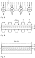
- An in Fig. 1 to 3 illustrated tubular mat 1 has five tube sections 2.
- the tube sections 2 are each oriented with their tube longitudinal axis 3 parallel to each other.
- Two tube sections 2 are each connected to each other by a web section 4. According to the embodiment shown so five tube sections 2 and four web sections 4 are provided.
- Each tube section 2 has a tube wall with a tube wall thickness d w in the range of 10 ⁇ m to 200 ⁇ m, preferably between 10 ⁇ m and 50 ⁇ m.
- An inner diameter d i of a hose section 2 is between 10 ⁇ m and 1000 ⁇ m, preferably between 10 ⁇ m and 500 ⁇ m.
- an outer diameter d a of a hose section is between 30 ⁇ m and 1400 ⁇ m.
- the web portion 4 has a thickness d S of about 10 .mu.m to 200 .mu.m.
- the thickness d S of the web section 4 is oriented perpendicular to a mat plane 5.
- the mat plane 5 corresponds to the drawing plane in Fig. 1 ,
- Fig. 1 to 3 There are also more or less than those in Fig. 1 to 3 shown five hose sections 2 per hose mat 1 possible.
- the number, the size of the tube sections 2 and the number and size of the web sections 4 depend on the intended use of the tubular mat 1. In particular, the number of tube sections 2 of a tubular mat 1 is more than 10.
- the tubular mat 1 has a length L M , which is identical to a length L S of the individual tube sections 2.
- the length L S of the tube sections 2 is oriented parallel to the tube longitudinal axis 3.
- the tubular mat 1 has a width B M.
- the length L M of the tubular mat 1 is in particular between 5 cm and 30 cm, depending on the intended use of the oxygenator.
- the length L M is 5 cm for a tube mat 1 for a premature infant oxygenator or, for example, 30 cm for an adult person's oxygenator.
- the length L M of the tubular mat 1 is not limited. In particular, when the tubular mat 1 is produced by extrusion as described below, an arbitrary length L M can be provided. It is possible to provide the tubular mat 1 as a bundle product so that at a later date tubular mats 1 with a predetermined length L M or with different lengths can be cut.
- the width B M is preferably between 2 cm and 50 cm. The width B M is determined in particular by the dimensions of the tube sections 2 and by a tool for producing the tubular mat 1.
- the tubular mat 1 is made in one piece from silicone rubber.
- the tubular mat 1 has a uniform, homogeneous material.
- the tubular mat 1 has homogeneous material properties.
- three spacers 6 are respectively provided along the tube longitudinal axis 3.
- the spacers 6 are formed as spherical thickenings.
- the spacers 6 are each made of silicone rubber made in one piece with the hose mat 1.
- the spacers 6 have a perpendicular to the tube longitudinal axis 3 oriented round cross-sectional area.
- the spacers 6 have a thickness d Ab , which is oriented perpendicular to the mat plane 5 and has about 40 microns to 2000 microns.
- the tubular mat 1 is made by extrusion. It is conceivable to produce the tubular mat 1 by means of coextrusion and in particular to produce the tube sections 2 and the bar sections 4 from a first material and the spacers 6 from a second, different material by coextrusion.
- a length L Ab of the spacer 6 along the tube longitudinal axis 3 is identical to the thickness d Ab .
- the length L Ab is smaller than the length L S of the hose section 2.
- the thickness d Ab of the spacer 6 is greater than the outer diameter d a of the hose section 2.
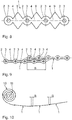
- the in Fig. 3 illustrated typical structure of the hose mat 1 corresponds to a pearl necklace.
- the spacers 6 are arranged along the tube sections 2.
- a center distance D M of the spacers 6 along the tube longitudinal axis 3 is identical.
- the spacers 6 are arranged regularly along the tube sections 2, ie with a constant center distance D M.
- the tube sections 2 are arranged in a direction perpendicular to the tube longitudinal axes 3 regularly, ie with identical tube section distances D S.
- the spacers 6 are arranged in a regular, rectangular grid.
- a grid spacing along the tube longitudinal axis 3 is the center distance D M.
- the spacers 6 are arranged perpendicularly to one another between adjacent tube sections 2, ie an imaginary connecting line of two spacers 6 of adjacent tube sections 2 is oriented perpendicular to the tube longitudinal axes 3, for example the section line III-III.
- the resulting, characteristic bead chain structures are identical along the tube longitudinal axis 3.
- the spacers 6 can each be arranged along a tube section 2, the spacers 6 of two adjacent tube sections 2 being offset along the tube longitudinal axes 3.
- the spacers 6 may be arranged such that three adjacent spacers 6 form the vertices of an equilateral triangle. This makes it possible to allow a tubular mat 1 with a densest surface arrangement of the spacers. This makes it possible to allow a higher areal density of the spacers 6, ie to increase the number of spacers 6 per area.
- Fig. 4 shows a further embodiment of a tubular mat 1.
- Components that correspond to those described above with reference to the FIG. 1 to 3 have the same reference numbers and will not be discussed again in detail.
- the hose mat 1 after Fig. 4 corresponds essentially to the tubular mat 1 according to Fig. 1 , wherein four tube sections 2 and three web sections 4 are provided. Along the tube longitudinal axis 3, five spacers 6 are provided at each tube section 2.
- a plurality of recesses 7 have a circular in the plane of the mat 5 contour, oval contour or rectangular contour with rounded corners.
- the recesses 7 are arranged in a direction parallel to the tube longitudinal axis 3 between two adjacent spacers 6 and in a direction perpendicular to the tube longitudinal axes 3 between two adjacent tube sections 2.
- the recesses 7 penetrate the web sections 4 completely.
- the recesses 7 are holes.
- Fig. 5 to 7 show further embodiments of a tubular mat 1. Components which correspond to those described above with reference to the Fig. 1 to 4 have the same reference numbers and will not be discussed again in detail.
- the hose mat 1 according to Fig. 5 to 7 differs essentially from the previous tubular mats by the configuration of the spacers 6.
- the spacers 8 have a perpendicular to the tube longitudinal axis 3 oriented cross-sectional area with a star-shaped contour.
- the spacers 8 may have, in accordance with the spacers 6, a length L Ab reduced along the tube longitudinal axis 3 ( Fig. 6 ). It is also possible that exactly one spacer 8 along the hose longitudinal axis 3 is provided.
- the spacer 6 has a length L Ab , which is identical to the length L S of the hose portion 2 (FIG. Fig. 7 ).
- Fig. 8 shows a further embodiment of a tubular mat 1.
- Components that correspond to those described above with reference to the Fig. 1 to 7 have the same reference numbers and will not be discussed again in detail.
- the tubular mat 1 differs from the previous tubular mats in that the spacers 9 are arranged on the web sections 4.
- the tube sections 2 are free of spacers.
- the spacers 9 are similar to the spacers 8 according to the hose mat 1 in Fig. 5 executed in a star shape.
- the spacers can either have a reduced length L Ab and / or a length L Ab which essentially corresponds to the length L S of the hose section 2.
- the tube bundle 10 has a bundle longitudinal axis 11.
- the tube bundle 10 is designed roller-shaped and has a perpendicular to the bundle longitudinal axis 11 oriented circular cross-section.
- the bundle longitudinal axis 11 is oriented parallel to the tube longitudinal axes 3.
- a plurality of tubular mats 1 are connected to each other and then rolled up into the bundle 10.
- the number of tubular mats 1, which are rolled into a tube bundle 10 depends on the respective width B M of the tubular mats 1 and the intended use of the tube bundle 10 produced therewith.
- the individual tubular mats 1 are in Fig. 10 shown schematically.
- the tube mats are 1 in Fig. 9 shown without spacers. It is of course possible that the hose mats 1 according to FIGS. 9 and 10 Spacers, as described above, can be provided.
- the tubular mats 1 are offset from one another in a direction perpendicular to the tube longitudinal axes 3 oriented width direction of the tubular mats 1. This means that the tube sections 2 of a tube mat 1 bear against a web section 4 of the other tube mat 1 or at least be arranged there.
- tubular mats 1 intervene alternately.
- the tubular mats 1 are mechanically, in particular by a kind of positive engagement, held together. This results in an automatic fixation of the tubular mats 1 to each other.
- the tubular mats 1 are arranged overlapping in an overlapping area B.
- the overlapping region B is designed in such a way that in each case two tube sections 2 of a tubular mat 1 overlap with the respective other tubular mat 1 to be joined.
- the overlapping area B extends in the width direction of the respective tube mat 1. It is also possible to select the overlapping area B such that exactly one or three or more tube sections 2 of the tube mats 1 overlap each other.
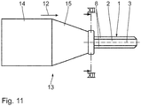
- Fig. 11 and 12 show a device for extruding a tubular mat 1 along an extrusion direction 12.
- the device 13 is in Fig. 11 shown schematically.
- the device 13 comprises an extrusion chamber 14 and a downstream in the extrusion direction 12, connected to the extrusion chamber 14 extrusion die 15.
- the extrusion chamber 14 is used for processing a plastic mass to be extruded.
- an extruder or an extruder screw is used for the preparation of plastic granules. This is done by heating and / or mixing the granules to melt the same.
- the plastic melt is then fed to the extrusion die 15 and extruded through it the hose mat 1 along the extrusion direction 12.
- a plastic raw material which comprises monomers and crosslinkers such as a catalyst or a radical initiator.
- This raw material is cold, so for example, at room temperature, fed by means of a screw conveyor of the extrusion die 15 and extruded through this the tubular mat 1 along the extrusion direction 12.
- the tubular mat 1 is heated so that a thermal crosslinking of the monomers takes place.
- a tubular mat 1 that can be produced with the extrusion nozzle 15 has three tube sections and two bar sections arranged therebetween. Spacers can be integrally formed on each of an upper and lower side of the tube sections.
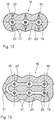
- a simultaneous extrusion of several tube sections and web sections to the tubular mat 1 is characterized by the in Fig. 12 shown in detail tool 16 allows.
- the tool 16 comprises in addition to the extrusion die 15 a plurality of mandrels 17.
- the extrusion die 15 comprises a solid housing 18 in which a mat cavity 19 is provided.
- the Mattenkavtician 19 comprises three, each having a longitudinal axis, parallel to the extrusion direction 12 arranged Schlauchkavmaschine 20 and two, each between two Schlauchkavticianen 20 arranged, the Schlauchkavticianen 20 connecting web cavities 21 coaxial with the respective longitudinal axis of a Schlauchkavtician 20 is the mandrel 17 in the Schlauchkavtician 20 arranged. Furthermore, in each case two spacer cavities 22 are provided on the tube cavities 20 in order to be able to form the spacers on the tubular mat 1.
- a tubular mat 1 according to the first embodiment with spacers in such a way that along the tube longitudinal axis 3 have a reduced length L Ab is an additional, in Fig. 11 and 12 not shown matrix required.
- This matrix has a mat cavity, which essentially corresponds to the mat cavity 19 of the extrusion nozzle 15. In the area of the hose cavities, however, the mat cavity of the additional die has no spacer cavities.
- the additional die is along the extrusion direction 12 of the extrusion die 15 downstream.
- the additional die is displaceable along the extrusion direction 12 relative to the device 13 and in particular relative to the tool 16.
- Such a method for the extrusion of hoses with variable outer diameter is from the US 5,511,965 known.
- Fig. 13 shows a further embodiment of a tool 16 which is substantially identical to the tool according to Fig. 12 , The main difference is the number of hose cavities 20.
- the tool 16 according to Fig. 13 six hose cavities 20, which are arranged in two rows of three one above the other in the tool 16. This can avoid that the tool 16 is made very flat and wide.
- the tool 16 is very compact.
- the two rows of three of the hose cavities 20 are connected to each other by a web cavity 21, wherein the connecting web cavity 21 is curved.
- the connecting web cavity 21 has an arc length along the curvature such that the length is identical to that of the remaining web cavities 21 which are provided between the hose cavities 20 arranged in each case in a row. Due to the elastic, flexible material properties of the silicone rubber can with the tool 16 in Fig. 13 extruded tubular mat 1 are arranged flat in a mat plane 5.
Landscapes
- Health & Medical Sciences (AREA)
- Engineering & Computer Science (AREA)
- Urology & Nephrology (AREA)
- Heart & Thoracic Surgery (AREA)
- Mechanical Engineering (AREA)
- Emergency Medicine (AREA)
- Anesthesiology (AREA)
- General Health & Medical Sciences (AREA)
- Veterinary Medicine (AREA)
- Vascular Medicine (AREA)
- Public Health (AREA)
- Biomedical Technology (AREA)
- Hematology (AREA)
- Life Sciences & Earth Sciences (AREA)
- Animal Behavior & Ethology (AREA)
- Manufacturing & Machinery (AREA)
- Chemical Kinetics & Catalysis (AREA)
- Chemical & Material Sciences (AREA)
- Extrusion Moulding Of Plastics Or The Like (AREA)
- External Artificial Organs (AREA)
- Braiding, Manufacturing Of Bobbin-Net Or Lace, And Manufacturing Of Nets By Knotting (AREA)
- Rigid Pipes And Flexible Pipes (AREA)
- Mattresses And Other Support Structures For Chairs And Beds (AREA)
Description
- Die Erfindung betrifft eine Schlauchmatte, ein Verfahren zum Herstellen einer derartigen Schlauchmatte sowie ein Werkzeug zum Extrudieren einer derartigen Schlauchmatte.
- Aus der
DE 28 38 659 C2 ist eine Schlauchanordnung für eine Viertelgemelksmaschine bekannt. Die Schlauchanordnung weist vier parallel zueinander laufende Schlauchleitungen auf, die an den Ecken eines Rhombus liegen. Die Schlauchanordnung ist keine Schlauchmatte. - Die
DE 35 87 787 T2 offenbart ein Verfahren zur Herstellung von Hohlfasern mittels Schmelzspinnen. Dazu sind speziell ausgeführte Spinndüsen erforderlich. Aus Kunststoff hergestellte Hohlfasern werden mit einer Spinnflüssigkeit benetzt. Ein derartiges Verfahren ist komplex. - Aus der
DE 18 08 271 A1 sind Schläuche bekannt, die aus Stabilitätsgründen Verstärkungselemente wie Rippen aufweisen können. Aus derDE 43 04 246 A1 ist ein Verfahren zur Herstellung eines Schlauchs bekannt. Eine Schlauchmatte ist aus derDE 43 04 246 A1 nicht bekannt. - Die
DE 27 04 678 A1 offenbart ein Verfahren zur Extrusion eines Kunststoffnetzes. - Bei einer Operation am offenen Herzen wird Blut eines Patienten in einer Herz-Lungen-Maschine extrakorporal mit Sauerstoff versorgt und gleichzeitig Kohlendioxid entfernt. Es handelt sich um die sogenannte extrakorporale Zirkulation (ECC). Eine ähnliche Blutbehandlung kommt auch bei einer extrakorporalen Membranoxygenierung (ECMO) zur pulmonalen Unterstützung eines Lungenpatienten zum Einsatz. In beiden Fällen werden Hohlfaserbündel verwendet, wobei Sauerstoff und Blut jeweils getrennt voneinander durch die von den Hohlfasern gebildeten Lumen bzw. durch die Zwischenräume der Hohlfasern geleitet werden.
- Ein derartiges Hohlfaserbündel ist aus der
DE 10 2010 000 820 A1 bekannt. Mehrere Schlauchabschnitte werden mit ihren Schlauchlängsachsen parallel zueinander angeordnet und in einer Richtung senkrecht zu den Schlauchlängsachsen mittels mindestens einer Wirknaht miteinander verwirkt. - Die
WO 2012/040 778 A1 offenbart einen Solarkollektor zum Erwärmen und Fördern von Flüssigkeiten. Der Solarkollektor weist eine Schlauchmatte auf, deren Einzelschläuche über ein Verteilerrohr verbunden sind. - Weitere Schlauchmatten sind bekannt aus der
GB 2 268 635 A US 4,332,752 . - Es ist eine Aufgabe der vorliegenden Erfindung, eine Schlauchmatte derart weiterzuentwickeln, dass sie vereinfacht hergestellt werden kann.
- Diese Aufgabe ist erfindungsgemäß gelöst durch eine Schlauchmatte mit den im Anspruch 1 angegebenen Merkmalen.
- Die erfindungsgemäße Schlauchmatte ist einstückig hergestellt. Insbesondere ist es nicht erforderlich, mehrere Schlauchabschnitte einzeln herzustellen, diese definiert zueinander anzuordnen und anschließend miteinander zu verwirken. Durch die einstückige Herstellung der Schlauchmatte sind Schlauchabschnitte automatisch zueinander definiert angeordnet und miteinander verbunden. Insbesondere sind die Schlauchabschnitte mit ihren Schlauchlängsachsen jeweils parallel zueinander angeordnet. Die Schlauchabschnitte sind jeweils durch einen Stegabschnitt miteinander verbunden. Die Herstellung der erfindungsgemäßen Schlauchmatte ist vereinfacht. Insbesondere ist die Anzahl der Verfahrensschritte reduziert. Die Anzahl der Einzelteile ist reduziert, so dass der Montageaufwand für die Schlauchmatte entfällt. Der Montageaufwand für die Herstellung eines Wärmetauschers insgesamt ist dadurch reduziert. Der Zeitaufwand und der Kostenaufwand für die Herstellung der erfindungsgemäßen Schlauchmatte sind reduziert. Insbesondere kann die Schlauchmatte durch Extrusion einstückig hergestellt werden. Das Risiko von Verunreinigungen bei der Herstellung der Schlauchmatte ist minimiert, da insbesondere ein Verwirken mit Wirkfäden und somit ein Einbringen von Staub und/oder Fasernabrieb ausgeschlossen ist. Die Schlauchmatte weist hinsichtlich ihrer Anwendung eine erhöhte Zuverlässigkeit auf. Die Ausschussrate bei der Herstellung der Schlauchmatte ist reduziert. Das Risiko, dass eine unbemerkte Verunreinigung der Schlauchmatte zu einer Gesundheitsgefährdung eines Patienten führt, ist reduziert. Derartige Schlauchmatten können sowohl in einem Oxygenator für die extrakorporale Zirkulation (ECC) als auch für die extrakorporale Membranoxigenierung (ECMO) eingesetzt werden. Die Schlauchmatte eignet sich grundsätzlich auch zur Verwendung im Bereich der pharmazeutischen Industrie für sogenannte Bioreaktoren. Beispielsweise sind Fermenter bekannt, bei welchen eine Bakterienkultur in Lösung durch Hohlfasern mit Sauerstoff versorgt wird. Derartige Hohlfasern können durch die Schlauchmatte abgebildet werden. Es ist auch bekannt, Oxygenierungsfasern bei der Gewebezüchtung, dem sogenannten Tissue Engineering, einzusetzen. Die Schlauchmatten können auch als Wärmetauschermatten beispielsweise in einer Fußbodenheizung, einer Wandheizung und/oder entsprechenden Kühlelementen Verwendung finden. Die erfindungsgemäße Schlauchmatte ist als Matte in einer Ausgangsanordnung im Wesentlichen flächig ausgeführt. Das bedeutet, dass die Längsachsen der Schlauchabschnitte in einer Mattenebene anordenbar sind. Es ist möglich, die Schlauchmatte einzeln oder mit mindestens einer weiteren Schlauchmatte zu einem Schlauchmattenbündel einzurollen, sodass insbesondere ein im Wesentlichen zylinderförmiges Schlauchmattenbündel resultiert.
- Eine Schlauchmatte mit mindestens einem Abstandshalter, der eine senkrecht zu einer Mattenebene orientierte Dicke aufweist, die größer ist als ein Außendurchmesser eines Schlauchabschnitts ermöglicht eine vereinfachte Herstellung eines Schlauchbündels aus mehreren Schlauchmatten. Durch den mindestens einen Abstandshalter können die Schlauchabschnitte einer Schlauchmatte in einem definierten Abstand zueinander angeordnet werden. Insbesondere werden mehrere Schlauchmatten zu einem Schlauchbündel aufgerollt bzw. aufgewickelt.
- Eine Schlauchmatte nach Anspruch 2 ermöglicht eine flexible Verbindung der Schlauchmatten zu einem Schlauchmattenbündel.
- Eine Schlauchmatte nach einem der Ansprüche 3 oder 4 ermöglicht eine Verbindung einzelner Schlauchmatten miteinander mit einer erhöhten Festigkeit. Einzelne Abstandshalter können insbesondere in korrespondierende Zwischenräume einer anderen Schlauchmatte bei der Verbindung der einzelnen Schlauchmatten miteinander eingreifen. Der Materialeinsatz für die Herstellung der Abstandshalter entlang der Schlauchlängsachse gegenüber einem durchgängigen, stegförmigen Abstandshalter ist reduziert.
- Eine Schlauchmatte nach Anspruch 5 weist ein erhöhtes Flächenträgheitsmoment bezüglich einer Biegung um eine zu den Schlauchlängsachsen quer gerichteten Richtung auf. Die Schlauchmatte ist stabil ausgeführt. Insbesondere sind die Abstandshalter als durchgängige Stege ausgeführt. Derartige Stege sind vereinfacht herstellbar.
- Eine Schlauchmatte nach Anspruch 6 ermöglicht eine verbesserte Verbindung mit einer anderen Schlauchmatte zu einem Schlauchmattenbündel.
- Eine Schlauchmatte nach Anspruch 7 ermöglicht Materialeinsparung bei der Herstellung. Zusätzlich weist eine derartige Schlauchmatte eine erhöhte Diffusionsoberfläche auf.
- Eine Schlauchmatte nach Anspruch 8 ist vereinfacht herstellbar. Dadurch, dass mehrere Schlauchabschnitte gleichzeitig als einstückiges Bauteil in Form der Schlauchmatte extrudiert werden, kann die Matte insgesamt besser beim Extrudieren abgezogen werden. Die Gefahr eines Reißens einzelner Silikonschlauchabschnitte ist reduziert. Die Herstellung der Schlauchmatte ist zuverlässig durchführbar. Eine derartige Schlauchmatte ist insbesondere für den Einsatz in einem Oxygenatormodul bei der ECC geeignet. Alternativ ist es auch möglich, Polyurethan oder andere thermoplastische Polymere für die Herstellung der Schlauchmatte zu verwenden. In diesem Fall kann die Schlauchmatte auch für Wärmetauscher im Allgemeinen verwendet werden.
- Es ist eine weitere Aufgabe der vorliegenden Erfindung, ein Verfahren zum Herstellen einer Schlauchmatte zu vereinfachen.
- Diese Aufgabe wird durch ein Verfahren mit den im Anspruch 9 angegebenen Merkmalen gelöst. Bei einem Verfahren zum Herstellen einer Schlauchmatte wird zunächst ein Werkzeug bereitgestellt, mit dem eine Schlauchmatte entlang einer Extrusionsrichtung extrudiert werden kann. Anschließend erfolgt ein Extrudieren der Schlauchmatte, die mehrere entlang der Extrusionsrichtung angeordnete Schlauchabschnitte und mindestens einen, zwei Schlauchabschnitte verbindenden Stegabschnitt aufweist. Dadurch ist es möglich, mehrere Schlauchabschnitte, die jeweils durch Stegabschnitte miteinander verbunden sind, einstückig in einem Verfahrensschritt durch Extrudieren herzustellen. Ein derartiges Verfahren ist wirtschaftlich. Dadurch, dass mehrere Schlauchabschnitte durch die Stegabschnitte miteinander verbunden sind, entsteht eine Schlauchmatte mit einer verbesserten Strukturstabilität. Insbesondere kann die Schlauchmatte besser aus dem Extrusionswerkzeug abgezogen werden. Insbesondere ist auch die Handhabung für möglicherweise nachgelagerte Verfahrensschritte verbessert. Insbesondere kann eine derart hergestellte Schlauchmatte besser abgelegt und/oder gewickelt werden. Beispielsweise können mehrere Schlauchmatten zu einem Schlauchbündel verbunden werden, indem insbesondere ein Schlauchabschnitt einer ersten Schlauchmatte auf einem Stegabschnitt einer zweiten Schlauchmatte angeordnet und diese anschließend zu einem Schlauchbündel durch Rollen verbunden werden.
- Es ist außerdem eine weitere, nicht erfindungsgemäße Aufgabe der vorliegenden Erfindung, ein Werkzeug zum Extrudieren einer Schlauchmatte bereitzustellen.
- Ein derartiges Werkzeug dient zum Extrudieren einer Schlauchmatte entlang einer Extrusionsrichtung. Das Werkzeug weist eine Extrusionsdüse auf, die mit einer Extrusionskammer verbindbar ist. In der Extrusionskammer kann die zu extrudierende Kunststoffschmelze bevorratet sein. Die Extrusionsdüse weist eine Mattenkavität auf, die mehrere, jeweils eine Längsachse aufweisende und parallel zur Extrusionsrichtung angeordnete Schlauchkavitäten sowie mindestens eine, jeweils zwei benachbarte Schlauchkavitäten verbindende Stegkavitäten umfasst. In jeder Schlauchkavität ist ein Dorn angeordnet, so dass zwischen einer Außenwand des Dorns und einer Innenwand der Schlauchkavität ein im Wesentlichen ringringförmig ausgeführter Spalt gebildet wird. Da mehrere Schlauchkavitäten vorgesehen sind, sind auch mehrere Dorne von dem Werkzeug umfasst.
- Ausführungsbeispiele der Erfindung werden nachfolgend anhand der Zeichnung näher erläutert. In dieser zeigen:
- Fig. 1
- eine Draufsicht auf eine nicht-erfindungsgemäße Schlauchmatte,
- Fig. 2
- eine Seitenansicht der Schlauchmatte in
Fig. 1 , - Fig. 3
- eine Schnittdarstellung gemäß Linie III-III in
Fig. 1 , - Fig. 4
- eine
Fig. 1 entsprechende Draufsicht einer Schlauchmatte gemäß einer nicht-erfindungsgemäßen Ausführungsform, - Fig. 5
- eine
Fig. 3 entsprechende Schnittdarstellung einer nichterfindungsgemäßen Ausführungsform einer Schlauchmatte, - Fig. 6, 7
-
Fig. 2 entsprechende Seitenansichten nichterfindungsgemäßen Ausführungsformen einer Schlauchmatte, - Fig. 8
- eine
Fig. 3 entsprechende Schnittdarstellung einer erfindungsgemäßen Ausführungsform einer Schlauchmatte, - Fig. 9, 10
- schematische Darstellungen zur Anordnung mehrerer Schlauchmatten für die Herstellung eines Schlauchbündels,
- Fig. 11
- eine schematische Darstellung einer Anlage mit einem Werkzeug zum Extrudieren einer Schlauchmatte,
- Fig. 12
- eine Schnittdarstellung gemäß Linie XII-XII in
Fig. 11 und - Fig. 13
- eine
Fig. 12 entsprechende Schnittdarstellung eines Werkzeugs gemäß einer weiteren Ausführungsform. - Eine in
Fig. 1 bis 3 dargestellte Schlauchmatte 1 weist fünf Schlauchabschnitte 2 auf. Die Schlauchabschnitte 2 sind jeweils mit ihrer Schlauchlängsachse 3 parallel zueinander orientiert. Jeweils zwei Schlauchabschnitte 2 sind jeweils durch einen Stegabschnitt 4 miteinander verbunden. Gemäß dem gezeigten Ausführungsbeispiel sind also fünf Schlauchabschnitte 2 und vier Stegabschnitte 4 vorgesehen. - Jeder Schlauchabschnitt 2 weist eine Schlauchwand mit einer Schlauchwanddicke dw im Bereich von 10 µm bis 200 µm auf, bevorzugt zwischen 10 µm und 50 µm. Ein Innendurchmesser di eines Schlauchabschnitts 2 beträgt zwischen 10 µm und 1000 µm, bevorzugt zwischen 10 µm und 500 µm. Entsprechend beträgt ein Außendurchmesser da eines Schlauchabschnitts zwischen 30 µm und 1400 µm.
- Der Stegabschnitt 4 weist eine Dicke dS von etwa 10 µm bis 200 µm auf. Die Dicke dS des Stegabschnitts 4 ist senkrecht zu einer Mattenebene 5 orientiert. Die Mattenebene 5 entspricht der Zeichenebene in
Fig. 1 . - Es sind auch mehr oder weniger als die in
Fig. 1 bis 3 dargestellten fünf Schlauchabschnitte 2 pro Schlauchmatte 1 möglich. Die Anzahl, die Größe der Schlauchabschnitte 2 sowie die Anzahl und die Größe der Stegabschnitte 4 richten sich nach dem Verwendungszweck der Schlauchmatte 1. Insbesondere beträgt die Anzahl der Schlauchabschnitte 2 einer Schlauchmatte 1 mehr als 10. - Die Schlauchmatte 1 weist eine Länge LM auf, die identisch ist mit einer Länge LS der einzelnen Schlauchabschnitte 2. Die Länge LS der Schlauchabschnitte 2 ist parallel zur Schlauchlängsachse 3 orientiert. Weiterhin weist die Schlauchmatte 1 eine Breite BM auf.
- Die Länge LM der Schlauchmatte 1 beträgt insbesondere zwischen 5 cm und 30 cm in Abhängigkeit des Verwendungszwecks des Oxygenators. Beispielsweise beträgt die Länge LM 5 cm bei einer Schlauchmatte 1 für einen Oxygenator eines Frühgeborenen oder beispielsweise 30 cm für einen Oxygenator einer erwachsenen Person. Bei der Herstellung ist die Länge LM der Schlauchmatte 1 nicht limitiert. Insbesondere dann, wenn die Schlauchmatte 1 wie nachfolgend noch beschrieben durch Extrusion hergestellt wird, kann eine beliebige Länge LM bereitgestellt werden. Es ist möglich, die Schlauchmatte 1 als Bundware zur Verfügung zu stellen, so dass zu einem späteren Zeitpunkt Schlauchmatten 1 mit einer vorgegebenen Länge LM oder mit verschiedenen Längen zugeschnitten werden können. Die Breite BM beträgt vorzugsweise zwischen 2 cm und 50 cm. Die Breite BM ist insbesondere durch die Dimensionen der Schlauchabschnitte 2 und durch ein Werkzeug zur Herstellung der Schlauchmatte 1 mitbestimmt.
- Die Schlauchmatte 1 ist einstückig aus Silikonkautschuk hergestellt. Die Schlauchmatte 1 weist ein einheitliches, homogenes Material auf. Die Schlauchmatte 1 weist homogene Materialeigenschaften auf. An den Schlauchabschnitten 2 sind jeweils entlang der Schlauchlängsachse 3 drei Abstandshalter 6 vorgesehen. Die Abstandshalter 6 sind als kugelförmige Verdickungen ausgebildet. Die Abstandshalter 6 sind jeweils aus Silikonkautschuk einstückig mit der Schlauchmatte 1 ausgeführt. Die Abstandshalter 6 weisen eine senkrecht zur Schlauchlängsachse 3 orientierte runde Querschnittsfläche auf. Die Abstandshalter 6 weisen eine Dicke dAb auf, die senkrecht zu der Mattenebene 5 orientiert ist und etwa 40 µm bis 2000 µm aufweist.
- Die Schlauchmatte 1 ist durch Extrusion hergestellt. Es ist denkbar, die Schlauchmatte 1 mittels Koextrusion herzustellen und insbesondere die Schlauchabschnitte 2 und die Stegabschnitte 4 aus einem ersten Material und die Abstandshalter 6 aus einem zweiten, davon verschiedenen Material durch Koextrusion herzustellen.
- Gemäß dem gezeigten Ausführungsbeispiel ist eine Länge LAb der Abstandshalter 6 entlang der Schlauchlängsachse 3 identisch mit der Dicke dAb. Insbesondere ist die Länge LAb kleiner als die Länge LS des Schlauchabschnitts 2. Die Dicke dAb des Abstandshalters 6 ist größer als der Außendurchmesser da des Schlauchabschnitts 2. Die in
Fig. 3 dargestellte typische Struktur der Schlauchmatte 1 entspricht der einer Perlenkette. Bei der Ausführungsform der Schlauchmatte 1 in denFig. 1 bis 3 sind die Abstandshalter 6 entlang der Schlauchabschnitte 2 angeordnet. Ein Mittenabstand DM der Abstandshalter 6 entlang der Schlauchlängsachse 3 ist identisch. Die Abstandshalter 6 sind entlang der Schlauchabschnitte 2 regelmäßig, d. h. mit gleichbleibenden Mittenabstand DM, angeordnet. Die Schlauchabschnitte 2 sind in einer Richtung senkrecht zu den Schlauchlängsachsen 3 regelmäßig, d. h. mit identischen Schlauchabschnittsabständen DS angeordnet. In dem Ausführungsbeispiel sind die Abstandshalter 6 in einem regelmäßigen, rechteckförmigen Raster angeordnet. Ein Rasterabstand entlang der Schlauchlängsachse 3 ist der Mittenabstand DM. Ein Rasterabstand in einer zu den Schlauchlängsachsen 3 senkrecht orientierten Richtung ist der Schlauchabschnittsabstand DS. Es ist auch denkbar, dass die Abstände DM und/oder DS bei einer Schlauchmatte 1 variieren. Die Abstandshalter 6 sind zwischen benachbarten Schlauchabschnitten 2 senkrecht zueinander angeordnet, d. h. eine gedachte Verbindungslinie von zwei Abstandshaltern 6 benachbarter Schlauchabschnitte 2 ist senkrecht zu den Schlauchlängsachsen 3 orientiert wie beispielsweise die Schnittlinie III-III. Die daraus resultierenden, charakteristischen Perlenkettenstrukturen sind entlang der Schlauchlängsachse 3 identisch. - Gemäß einer weiteren nicht dargestellten Ausführungsform einer Schlauchmatte 1 können die Abstandshalter 6 jeweils entlang eines Schlauchabschnitts 2 angeordnet sein, wobei die Abstandshalter 6 zweier benachbarter Schlauchabschnitte 2 entlang der Schlauchlängsachsen 3 versetzt zueinander angeordnet sind. Insbesondere ist es denkbar, den Schlauchabschnittsabstand DS und den Mittabstand DM derart zu wählen, dass sämtliche Abstandshalter 6 der Schlauchmatte 1 mit gleichem Abstand paarweise zueinander angeordnet sind. Insbesondere können die Abstandshalter 6 derart angeordnet sein, dass drei benachbarte Abstandshalter 6 die Eckpunkte eines gleichseitigen Dreiecks bilden. Dadurch ist es möglich, eine Schlauchmatte 1 mit einer dichtesten Flächenanordnung der Abstandshalter zu ermöglichen. Dadurch ist es möglich, eine höhere Flächendichte der Abstandshalter 6 zu ermöglichen, also die Anzahl der Abstandshalter 6 pro Fläche zu erhöhen.
- Es ist auch denkbar, die Perlenkettenstruktur entlang der Schlauchlängsachsen 3 veränderlich auszuführen.
-
Fig. 4 zeigt eine weitere Ausführung einer Schlauchmatte 1. Komponenten, die denjenigen entsprechen, die vorstehend unter Bezugnahme auf dieFig. 1 bis 3 erläutert wurden, tragen die gleichen Bezugsziffern und werden nicht nochmals im Einzelnen diskutiert. - Die Schlauchmatte 1 nach
Fig. 4 entspricht im Wesentlichen der Schlauchmatte 1 gemäßFig. 1 , wobei vier Schlauchabschnitte 2 und drei Stegabschnitte 4 vorgesehen sind. Entlang der Schlauchlängsachse 3 sind an jedem Schlauchabschnitt 2 fünf Abstandshalter 6 vorgesehen. Wesentlicher Unterschied der Schlauchmatte 1 gemäßFig. 4 gegenüber der Schlauchmatte 1 inFig. 1 sind mehrere Ausnehmungen 7. Die Ausnehmungen 7 weisen eine in der Mattenebene 5 kreisförmige Kontur, ovale Kontur oder rechteckige Kontur mit abgerundeten Ecken auf. Die Ausnehmungen 7 sind in einer Richtung parallel zur Schlauchlängsachse 3 zwischen zwei benachbarten Abstandshaltern 6 und in einer Richtung senkrecht zu den Schlauchlängsachsen 3 zwischen zwei benachbarten Schlauchabschnitten 2 angeordnet. Die Ausnehmungen 7 durchdringen die Stegabschnitte 4 vollständig. Die Ausnehmungen 7 sind Löcher. -
Fig. 5 bis 7 zeigen weitere Ausführungen einer Schlauchmatte 1. Komponenten, die denjenigen entsprechen, die vorstehend unter Bezugnahme auf dieFig. 1 bis 4 erläutert wurden, tragen die gleichen Bezugsziffern und werden nicht nochmals im Einzelnen diskutiert. - Die Schlauchmatte 1 gemäß
Fig. 5 bis 7 unterscheidet sich im Wesentlichen von den vorangegangenen Schlauchmatten durch die Ausgestaltung der Abstandshalter 6. Die Abstandshalter 8 weisen eine senkrecht zur Schlauchlängsachse 3 orientierte Querschnittsfläche mit einer sternförmigen Kontur auf. Die Abstandshalter 8 können entsprechend den Abstandshaltern 6 eine entlang der Schlauchlängsachse 3 reduzierte Länge LAb aufweisen (Fig. 6 ). Es ist auch möglich, dass genau ein Abstandshalter 8 entlang der Schlauchlängsachse 3 vorgesehen ist. In diesem Fall weist der Abstandshalter 6 eine Länge LAb auf, die identisch ist mit der Länge LS des Schlauchabschnitts 2 (Fig. 7 ). -
Fig. 8 zeigt eine weitere Ausführung einer Schlauchmatte 1. Komponenten, die denjenigen entsprechen, die vorstehend unter Bezugnahme auf dieFig. 1 bis 7 erläutert wurden, tragen die gleichen Bezugsziffern und werden nicht nochmals im Einzelnen diskutiert. - Die Schlauchmatte 1 unterscheidet sich von den vorhergehenden Schlauchmatten dadurch, dass die Abstandshalter 9 an den Stegabschnitten 4 angeordnet sind. Insbesondere sind die Schlauchabschnitte 2 frei von Abstandshaltern. Die Abstandshalter 9 sind ähnlich wie die Abstandshalter 8 gemäß der Schlauchmatte 1 in
Fig. 5 sternförmig ausgeführt. - Gemäß einer weiteren, nicht in den Figuren dargestellten Ausführungsform ist es möglich, mehrere, verschieden geformte Abstandshalter an einer Schlauchmatte vorzusehen. Es ist möglich, die Abstandshalter sowohl im Bereich der Schlauchabschnitte als auch im Bereich der Stegabschnitte vorzusehen. Die Abstandshalter können entweder eine reduzierte Länge LAb und/oder eine Länge LAb aufweisen, die im Wesentlichen der Länge LS des Schlauchabschnitts 2 entspricht.
- Im Folgenden wird unter Bezugnahme auf die
Fig. 9 und 10 ein Verfahren zur Herstellung eines Schlauchbündels 10 näher erläutert. Das Schlauchbündel 10 weist eine Bündellängsachse 11 auf. Das Schlauchbündel 10 ist rollenförmig ausgeführt und weist einen senkrecht zur Bündellängsachse 11 orientierten kreisförmigen Querschnitt auf. Die Bündellängsachse 11 ist parallel zu den Schlauchlängsachsen 3 orientiert. - Zur Herstellung des Schlauchbündels 10 werden mehrere Schlauchmatten 1 miteinander verbunden und anschließend zu dem Bündel 10 aufgerollt. Die Anzahl der Schlauchmatten 1, die zu einem Schlauchbündel 10 gerollt werden, hängt von der jeweiligen Breite BM der Schlauchmatten 1 und dem Einsatzzweck des damit hergestellten Schlauchbündels 10 ab. Die einzelnen Schlauchmatten 1 sind in
Fig. 10 schematisch dargestellt. Insbesondere ist die exakte Querschnittskontur einer Schlauchmatte, die sich aus den durch die Stegabschnitte miteinander verbundenen Schlauchabschnitte 2 ergibt, nicht im Einzelnen dargestellt. Diese Kontur ist inFig. 9 dargestellt. Daraus geht hervor, dass an einer ersten, inFig. 9 unten, links dargestellten Schlauchmatte 1 eine weitere, zweite Schlauchmatte 1 angeordnet wird. Die weitere Schlauchmatte 1 ist inFig. 9 rechts, oben dargestellt. Aus Gründen der einfacheren Darstellung sind die Schlauchmatten 1 inFig. 9 ohne Abstandshalter dargestellt. Es ist selbstverständlich möglich, dass an den Schlauchmatten 1 gemäßFig. 9 und 10 Abstandshalter, wie vorstehend beschrieben, vorgesehen sein können. Die Schlauchmatten 1 sind in einer senkrecht zu den Schlauchlängsachsen 3 orientierten Breitenrichtung der Schlauchmatten 1 versetzt zueinander angeordnet. Das bedeutet, dass die Schlauchabschnitte 2 der einen Schlauchmatte 1 an einem Stegabschnitt 4 der anderen Schlauchmatte 1 anliegen oder zumindest dort angeordnet werden. - Das bedeutet also, dass die Schlauchmatten 1 wechselweise ineinander eingreifen. Die Schlauchmatten 1 sind mechanisch, insbesondere durch eine Art Formschluss, aneinander gehalten. Dadurch ergibt sich eine automatische Fixierung der Schlauchmatten 1 aneinander. Ein aktives Befestigen, beispielsweise durch Kleben der einzelnen Schlauchmatten miteinander, ist nicht erforderlich.
- Die Schlauchmatten 1 sind in einem Überlappungsbereich B überlappend angeordnet. Der Überlappungsbereich B ist gemäß dem gezeigten Ausführungsbeispiel derart ausgeführt, dass jeweils zwei Schlauchabschnitte 2 einer Schlauchmatte 1 mit der jeweils anderen, zu verbindenden Schlauchmatte 1 überlappen. Der Überlappungsbereich B erstreckt sich in Breitenrichtung der jeweiligen Schlauchmatte 1. Es ist auch möglich, den Überlappungsbereich B so zu wählen, dass genau eine oder drei oder mehr Schlauchabschnitte 2 der Schlauchmatten 1 jeweils überlappen.
-
Fig. 11 und12 zeigen eine Vorrichtung zum Extrudieren einer Schlauchmatte 1 entlang einer Extrusionsrichtung 12. Die Vorrichtung 13 ist inFig. 11 schematisch dargestellt. Die Vorrichtung 13 umfasst eine Extrusionskammer 14 und eine in Extrusionsrichtung 12 nachgelagerte, mit der Extrusionskammer 14 verbundene Extrusionsdüse 15. Die Extrusionskammer 14 dient zum Aufbereiten einer zu extrudierenden Kunststoffmasse. Zum Aufbereiten einer thermoplastischen Kunststoffmasse dient ein Extruder oder eine Extruderschnecke zum Aufbereiten von Kunststoffgranulat. Dies erfolgt durch Beheizen und/oder Mischen des Granulats, um dasselbe zu schmelzen. Die Kunststoffschmelze wird dann der Extrusionsdüse 15 zugeführt und durch diese die Schlauchmatte 1 entlang der Extrusionsrichtung 12 extrudiert. - Für die Verarbeitung von Elastomeren wie beispielsweise Silikon wird zunächst eine plastische Rohmasse bereit gestellt, die Monomere und Vernetzer wie beispielsweise einen Katalysator oder einen Radikalstarter umfasst. Diese Rohmasse wird kalt, also beispielsweise bei Raumtemperatur, mittels eines Schneckenförderers der Extrusionsdüse 15 zugeführt und durch diese die Schlauchmatte 1 entlang der Extrusionsrichtung 12 extrudiert. Nach dieser Formgebung wird die Schlauchmatte 1 erwärmt, so dass ein thermisches Vernetzen der Monomere erfolgt.
- Gemäß dem gezeigten Ausführungsbeispiel weist eine mit der Extrusionsdüse 15 herstellbare Schlauchmatte 1 drei Schlauchabschnitte und zwei dazwischen angeordnete Stegabschnitte auf. Jeweils an einer Ober- und Unterseite der Schlauchabschnitte können Abstandshalter einstückig angeformt werden. Ein gleichzeitiges Extrudieren mehrerer Schlauchabschnitte und Stegabschnitte zu der Schlauchmatte 1 wird durch das in
Fig. 12 im Einzelnen dargestellte Werkzeug 16 ermöglicht. Das Werkzeug 16 umfasst neben der Extrusionsdüse 15 mehrere Dorne 17. Die Extrusionsdüse 15 umfasst ein massives Gehäuse 18, in dem eine Mattenkavität 19 vorgesehen ist. Die Mattenkavität 19 umfasst drei, jeweils eine Längsachse aufweisende, parallel zur Extrusionsrichtung 12 angeordnete Schlauchkavität 20 und zwei, jeweils zwischen zwei Schlauchkavitäten 20 angeordnete, die Schlauchkavitäten 20 verbindende Stegkavitäten 21. Koaxial zu der jeweiligen Längsachse einer Schlauchkavität 20 ist der Dorn 17 in der Schlauchkavität 20 angeordnet. Weiterhin sind an den Schlauchkavitäten 20 jeweils zwei Abstandshalterkavitäten 22 vorgesehen, um die Abstandshalter an der Schlauchmatte 1 ausbilden zu können. - Für die Herstellung einer Schlauchmatte 1 gemäß dem ersten Ausführungsbeispiel mit Abstandshaltern derart, die entlang der Schlauchlängsachse 3 eine reduzierte Länge LAb aufweisen, ist eine zusätzliche, in
Fig. 11 und12 nicht dargestellte Matrix erforderlich. Diese Matrix weist eine Mattenkavität auf, die im Wesentlichen der Mattenkavität 19 der Extrusionsdüse 15 entspricht. Im Bereich der Schlauchkavitäten weist die Mattenkavität der zusätzlichen Matrize allerdings keine Abstandshalterkavitäten auf. Die zusätzliche Matrize ist entlang der Extrusionsrichtung 12 der Extrusionsdüse 15 nachgelagert. Die zusätzliche Matrize ist entlang der Extrusionsrichtung 12 relativ zu der Vorrichtung 13 und insbesondere relativ zu dem Werkzeug 16 verlagerbar. Ein derartiges Verfahren für die Extrusion von Schläuchen mit veränderlichem Außendurchmesser ist aus derUS 5,511,965 bekannt. -
Fig. 13 zeigt eine weitere Ausführung eines Werkzeugs 16, das im Wesentlichen identisch ist mit dem Werkzeug gemäßFig. 12 . Wesentlicher Unterschied ist die Anzahl der Schlauchkavitäten 20. Insgesamt weist das Werkzeug 16 gemäßFig. 13 sechs Schlauchkavitäten 20 auf, die in zwei Dreierreihen übereinander in dem Werkzeug 16 angeordnet sind. Dadurch kann vermieden werden, dass das Werkzeug 16 sehr flach und breit ausgeführt ist. Das Werkzeug 16 ist sehr kompakt aufgebaut. Die zwei Dreierreihen der Schlauchkavitäten 20 sind durch eine Stegkavität 21 miteinander verbunden, wobei die verbindende Stegkavität 21 gekrümmt ausgeführt ist. Die verbindenden Stegkavität 21 weist eine Bogenlänge entlang der Krümmung derart auf, dass die Länge identisch ist mit der der übrigen Stegkavitäten 21, die zwischen den jeweils in einer Reihe angeordneten Schlauchkavitäten 20 vorgesehen sind. Aufgrund der elastischen, flexiblen Materialeigenschaften des Silikonkautschuks kann die mit dem Werkzeug 16 inFig. 13 extrudierte Schlauchmatte 1 flächig in einer Mattenebene 5 angeordnet werden. - Durch die kompakte Ausführung des Werkzeugs 16 ist es möglich, einen erforderlichen Betriebsdruck für die Kunststoffschmelze bzw. die Silikonrohmasse und damit die Werkzeugschließkräfte bei der Herstellung einer Schlauchmatte 1 zu reduzieren. Gleichzeitig ist es möglich, besonders große Schlauchmatten 1, d. h. mit einer großen Anzahl von nebeneinander angeordneten Schlauchabschnitten, effektiv und vorteilhaft herzustellen.
Claims (9)
- Schlauchmatte umfassenda. mehrere, jeweils eine Schlauchlängsachse (3) aufweisende Schlauchabschnitte (2) undb. mindestens einen zwei Schlauchabschnitte (2) verbindenden Stegabschnitt (4),c. mindestens einen Abstandshalter (6; 8; 9), der eine senkrecht zu einer Mattenebene (5) orientierte Dicke (dAb) aufweist, die größer ist als ein Außendurchmesser (da) eines Schlauchabschnitts (2),wobei die Schlauchmatte (1) einstückig hergestellt ist,
dadurch gekennzeichnet, dass
der Abstandshalter (6; 8; 9) an einem Stegabschnitt (4) und zwischen zwei benachbarten Schlauchabschnitten (2) angeordnet ist, und die Schlauchmatte aufrollbar ist. - Schlauchmatte gemäß Anspruch 1, dadurch gekennzeichnet, dass der Abstandshalter (6; 8; 9) an einem Schlauchabschnitt (2) angeordnet ist.
- Schlauchmatte gemäß einem der vorstehenden Ansprüche, dadurch gekennzeichnet, dass der Abstandshalter (6; 8; 9) entlang der Schlauchlängsachse (3) eine Länge (LAb) aufweist, die kleiner ist als eine Länge (Ls) der Schlauchabschnitte (2).
- Schlauchmatte gemäß Anspruch 3, gekennzeichnet durch mehrere Abstandshalter (6; 8; 9) entlang der Schlauchlängsachse (3).
- Schlauchmatte gemäß Anspruch 1 oder 2, dadurch gekennzeichnet, dass der Abstandshalter (6; 8; 9) entlang der Schlauchlängsachse (3) eine Länge (LAb) aufweist, die im Wesentlichen gleich groß ist wie eine Länge (Ls) der Schlauchabschnitte (2).
- Schlauchmatte gemäß einem der vorstehenden Ansprüche, dadurch gekennzeichnet, dass der Abstandshalter (6; 8; 9) eine senkrecht zur Schlauchlängsachse (3) orientierte Querschnittsfläche aufweist, die eine kreisförmige oder sternförmige Kontur aufweist.
- Schlauchmatte gemäß einem der vorstehenden Ansprüche, gekennzeichnet durch mindestens eine in einem Stegabschnitt (4) angeordnete Ausnehmung (7).
- Schlauchmatte gemäß einem der vorstehenden Ansprüche, dadurch gekennzeichnet, dass die Schlauchmatte (1) aus Silikonkautschuk oder Polyurethan hergestellt ist.
- Verfahren zum Herstellen einer Schlauchmatte gemäß einem der vorstehenden Ansprüche umfassend die Verfahrensschritte- Bereitstellen eines Werkzeugs zum Extrudieren einer Schlauchmatte (1) entlang einer Extrusionsrichtung (12),- Extrudieren einer Schlauchmatte (1) mit mehreren entlang der Extrusionsrichtung (12) angeordneten Schlauchabschnitten (2) und mindestens einem zwei Schlauchabschnitte (2) verbindenden Stegabschnitt (4).
Priority Applications (1)
| Application Number | Priority Date | Filing Date | Title |
|---|---|---|---|
| EP17196737.5A EP3287188B1 (de) | 2012-07-04 | 2013-06-12 | Schlauchmatte |
Applications Claiming Priority (2)
| Application Number | Priority Date | Filing Date | Title |
|---|---|---|---|
| DE102012211617.6A DE102012211617A1 (de) | 2012-07-04 | 2012-07-04 | Schlauchmatte, Verfahren zum Herstellen einer derartigen Schlauchmatte sowie Werkzeug zum Extrudieren einer derartigen Schlauchmatte |
| PCT/EP2013/062087 WO2014005809A1 (de) | 2012-07-04 | 2013-06-12 | Schlauchmatte, verfahren zum herstellen einer derartigen schlauchmatte sowie werkzeug zum extrudieren einer derartigen schlauchmatte |
Related Child Applications (2)
| Application Number | Title | Priority Date | Filing Date |
|---|---|---|---|
| EP17196737.5A Division EP3287188B1 (de) | 2012-07-04 | 2013-06-12 | Schlauchmatte |
| EP17196737.5A Division-Into EP3287188B1 (de) | 2012-07-04 | 2013-06-12 | Schlauchmatte |
Publications (2)
| Publication Number | Publication Date |
|---|---|
| EP2869912A1 EP2869912A1 (de) | 2015-05-13 |
| EP2869912B1 true EP2869912B1 (de) | 2017-11-29 |
Family
ID=48670508
Family Applications (2)
| Application Number | Title | Priority Date | Filing Date |
|---|---|---|---|
| EP17196737.5A Active EP3287188B1 (de) | 2012-07-04 | 2013-06-12 | Schlauchmatte |
| EP13730511.6A Active EP2869912B1 (de) | 2012-07-04 | 2013-06-12 | Schlauchmatte und verfahren zum herstellen einer derartigen schlauchmatte |
Family Applications Before (1)
| Application Number | Title | Priority Date | Filing Date |
|---|---|---|---|
| EP17196737.5A Active EP3287188B1 (de) | 2012-07-04 | 2013-06-12 | Schlauchmatte |
Country Status (8)
| Country | Link |
|---|---|
| US (1) | US10328626B2 (de) |
| EP (2) | EP3287188B1 (de) |
| JP (1) | JP6151774B2 (de) |
| BR (1) | BR112014033058B1 (de) |
| DE (1) | DE102012211617A1 (de) |
| ES (2) | ES2757504T3 (de) |
| TR (1) | TR201802688T4 (de) |
| WO (1) | WO2014005809A1 (de) |
Families Citing this family (2)
| Publication number | Priority date | Publication date | Assignee | Title |
|---|---|---|---|---|
| US9194119B2 (en) | 2012-10-04 | 2015-11-24 | ST Global Partners, LLC | Peel and stick decoupling membrane |
| US9227353B2 (en) * | 2012-11-08 | 2016-01-05 | Solar Hydronics Corporation | Molding apparatus and method for operating same |
Family Cites Families (21)
| Publication number | Priority date | Publication date | Assignee | Title |
|---|---|---|---|---|
| US3205563A (en) * | 1956-06-21 | 1965-09-14 | Olin Mathieson | Finned structure and method of manufacture |
| US3015136A (en) * | 1957-10-17 | 1962-01-02 | Pawling Rubber Corp | Resilient mat structure |
| US3404446A (en) * | 1965-10-24 | 1968-10-08 | Peerless Of America | Method of securing fins in a heat exchanger |
| DE1808271A1 (de) * | 1968-09-10 | 1970-04-02 | Yukio Nishikawa | Kunstharzfolien oder Schlaeuche |
| JPS5144168A (de) * | 1974-10-11 | 1976-04-15 | Ube Nitto Kasei Co | |
| GB1548375A (en) * | 1975-04-16 | 1979-07-11 | Dunlop Ltd | Resilient structures |
| NO770019L (no) * | 1976-02-05 | 1977-08-08 | Conwed Corp | Fremgangsm}te for fremstilling av ekstrudert, ekstra lett nett og produkter fra denne fremgangsm}te. |
| JPS54101539A (en) * | 1978-01-27 | 1979-08-10 | Kobe Steel Ltd | Heat exchange pipe for use with water-sprinkling type, panel-shaped, liquefied natural gas evaporator and combination of such pipes and their manufacturing method |
| DE2838659C2 (de) * | 1978-09-05 | 1981-07-16 | Bio-Melktechnik Swiss Hoefelmayer & Co, Niederteufen, Aargau | Schlauchanordnung für eine Viertelgemelksmaschine |
| LU81735A1 (de) * | 1978-10-02 | 1980-01-24 | Akzo Nv | Dialysemembranhohlfadenkette |
| DE2842835C3 (de) * | 1978-10-02 | 1989-06-08 | Akzo Patente GmbH, 5600 Wuppertal | Dialysemembranhohlfadenkette |
| JPS5651210A (en) * | 1979-10-02 | 1981-05-08 | Fuji Syst Kk | Capillary tube assemblage and device for gas exchange |
| CA1272139A (en) * | 1984-11-16 | 1990-07-31 | Shoji Mizutani | Fluid separator, hollow fiber to be used for construction thereof and process for preparation of said hollow fibers |
| JPH0651758U (ja) * | 1990-03-13 | 1994-07-15 | 三星電子株式会社 | 冷蔵庫用蒸発器構造 |
| US5511965A (en) | 1991-10-11 | 1996-04-30 | Specialty Silicone Fabricators, Inc. | Apparatus for extruding tubing having a variable outer diameter |
| EP0578961A1 (de) * | 1992-07-11 | 1994-01-19 | Dipl.-Ing. Dr. Ernst Vogelsang GmbH & Co. KG | Kabelführungsrohrbündel aus einer Mehrzahl von Kunststoffrohren und Verfahren zur Herstellung |
| DE4304246A1 (de) * | 1993-02-12 | 1994-08-18 | Henn Gmbh & Co Kg | Verfahren und Vorrichtung zur Herstellung eines Schlauches unter Hinzunahme von Verbindungselementen |
| JP3059331U (ja) * | 1998-11-25 | 1999-07-09 | 厖 須原 | 自動洗車ブラシ用洗浄体及びそれを用いた自動洗車ブラシ |
| JP2009072941A (ja) * | 2007-09-19 | 2009-04-09 | Seiko Epson Corp | 押出成形チューブの製造方法及びその装置 |
| DE102010000820A1 (de) | 2010-01-12 | 2011-07-14 | Raumedic Ag, 95213 | Wärmetauscherkörper |
| EP2622249A1 (de) * | 2010-09-27 | 2013-08-07 | Boss Polymer Technologies Pty Ltd | Sonnenkollektor |
-
2012
- 2012-07-04 DE DE102012211617.6A patent/DE102012211617A1/de not_active Withdrawn
-
2013
- 2013-06-12 ES ES17196737T patent/ES2757504T3/es active Active
- 2013-06-12 BR BR112014033058-1A patent/BR112014033058B1/pt not_active IP Right Cessation
- 2013-06-12 TR TR2018/02688T patent/TR201802688T4/tr unknown
- 2013-06-12 JP JP2015518956A patent/JP6151774B2/ja not_active Expired - Fee Related
- 2013-06-12 WO PCT/EP2013/062087 patent/WO2014005809A1/de not_active Ceased
- 2013-06-12 EP EP17196737.5A patent/EP3287188B1/de active Active
- 2013-06-12 EP EP13730511.6A patent/EP2869912B1/de active Active
- 2013-06-12 US US14/412,601 patent/US10328626B2/en active Active
- 2013-06-12 ES ES13730511.6T patent/ES2660834T3/es active Active
Also Published As
| Publication number | Publication date |
|---|---|
| WO2014005809A1 (de) | 2014-01-09 |
| US10328626B2 (en) | 2019-06-25 |
| JP6151774B2 (ja) | 2017-06-21 |
| EP3287188A1 (de) | 2018-02-28 |
| EP2869912A1 (de) | 2015-05-13 |
| JP2015530278A (ja) | 2015-10-15 |
| US20150147522A1 (en) | 2015-05-28 |
| BR112014033058A2 (pt) | 2017-06-27 |
| ES2660834T3 (es) | 2018-03-26 |
| ES2757504T3 (es) | 2020-04-29 |
| DE102012211617A1 (de) | 2014-01-09 |
| EP3287188B1 (de) | 2019-08-21 |
| BR112014033058B1 (pt) | 2021-06-01 |
| TR201802688T4 (tr) | 2018-03-21 |
Similar Documents
| Publication | Publication Date | Title |
|---|---|---|
| EP0475419B1 (de) | Wegwerbekleidung und Verfahren zum Anbringen von elastischen Elementen um deren Beinöffnungen | |
| DE69613627T2 (de) | Gegossener Flächenhaftverschluss | |
| EP0626159B1 (de) | Decklage von Körperflüssigkeit absorbierenden Artikeln und Verfahren zur Herstellung derselben | |
| EP0632742B1 (de) | Hohlfadenbündel sowie verfahren und vorrichtung zu seiner herstellung | |
| EP0732141B1 (de) | Hohlfadenbündel sowie Stoff- und/oder Wärmetauscher | |
| DE69515447T2 (de) | Verfahren und Vorrichtung zur Herstellung eines Flächenhaftverschluss | |
| DE69430984T2 (de) | Verfahren zur Herstellung eines Flächenhaftverschlusses | |
| EP0350732B1 (de) | Langgestreckter Formstrang | |
| EP2862971B1 (de) | Werkstoff | |
| EP0264696A2 (de) | Vorrichtung zum Stoffaustausch | |
| EP0332907B1 (de) | Füllmaterial zur Behandlung von Flüssigkeiten sowie Verfahren zur Herstellung desselben | |
| EP2869912B1 (de) | Schlauchmatte und verfahren zum herstellen einer derartigen schlauchmatte | |
| DE2613386A1 (de) | Verfahren zur herstellung eines kunststoffrohres | |
| EP1333120B1 (de) | Papiermaschinenbespannung, insbesondere Pressfilz | |
| DE102010027973A1 (de) | Verfahren und Vorrichtung zur Herstellung eines Membranmodus | |
| DE60317317T2 (de) | Bandförmiges gussteil und band für kugelkette | |
| DE4231067C1 (de) | Verbindungselement aus einem Verbundwerkstoff mit Kohlenstoffasern | |
| WO2011086010A1 (de) | Wärmetauscherkörper | |
| EP1911565A2 (de) | Vorrichtung zur Herstellung von Verbund-Rohren | |
| EP3423173B1 (de) | Hohlfasermembran mit dreidimensionaler lockung | |
| DE3733542A1 (de) | Vorrichtung zum stoffaustausch | |
| WO2016005083A1 (de) | Extrudierte papiermaschinenbespannung und verfahren zur deren herstellung | |
| DE2902525A1 (de) | Verfahren zur herstellung von monofilaments | |
| WO2010028810A1 (de) | Nachgiebiger aufbau für eine matratze, polster oder kissen | |
| DE1785094B2 (de) | Verfahren zur Erzeugung von in Fasern aufspaltbaren Folienstreifen |
Legal Events
| Date | Code | Title | Description |
|---|---|---|---|
| PUAI | Public reference made under article 153(3) epc to a published international application that has entered the european phase |
Free format text: ORIGINAL CODE: 0009012 |
|
| 17P | Request for examination filed |
Effective date: 20150126 |
|
| AK | Designated contracting states |
Kind code of ref document: A1 Designated state(s): AL AT BE BG CH CY CZ DE DK EE ES FI FR GB GR HR HU IE IS IT LI LT LU LV MC MK MT NL NO PL PT RO RS SE SI SK SM TR |
|
| AX | Request for extension of the european patent |
Extension state: BA ME |
|
| DAX | Request for extension of the european patent (deleted) | ||
| 17Q | First examination report despatched |
Effective date: 20160524 |
|
| REG | Reference to a national code |
Ref country code: DE Ref legal event code: R079 Ref document number: 502013008933 Country of ref document: DE Free format text: PREVIOUS MAIN CLASS: B01D0063020000 Ipc: B01D0069080000 |
|
| RIC1 | Information provided on ipc code assigned before grant |
Ipc: B01D 69/08 20060101AFI20170511BHEP Ipc: B29C 47/20 20060101ALI20170511BHEP |
|
| GRAP | Despatch of communication of intention to grant a patent |
Free format text: ORIGINAL CODE: EPIDOSNIGR1 |
|
| INTG | Intention to grant announced |
Effective date: 20170613 |
|
| GRAS | Grant fee paid |
Free format text: ORIGINAL CODE: EPIDOSNIGR3 |
|
| GRAA | (expected) grant |
Free format text: ORIGINAL CODE: 0009210 |
|
| AK | Designated contracting states |
Kind code of ref document: B1 Designated state(s): AL AT BE BG CH CY CZ DE DK EE ES FI FR GB GR HR HU IE IS IT LI LT LU LV MC MK MT NL NO PL PT RO RS SE SI SK SM TR |
|
| REG | Reference to a national code |
Ref country code: CH Ref legal event code: EP |
|
| REG | Reference to a national code |
Ref country code: AT Ref legal event code: REF Ref document number: 949876 Country of ref document: AT Kind code of ref document: T Effective date: 20171215 |
|
| REG | Reference to a national code |
Ref country code: IE Ref legal event code: FG4D Free format text: LANGUAGE OF EP DOCUMENT: GERMAN |
|
| REG | Reference to a national code |
Ref country code: DE Ref legal event code: R096 Ref document number: 502013008933 Country of ref document: DE |
|
| REG | Reference to a national code |
Ref country code: NL Ref legal event code: FP |
|
| REG | Reference to a national code |
Ref country code: ES Ref legal event code: FG2A Ref document number: 2660834 Country of ref document: ES Kind code of ref document: T3 Effective date: 20180326 |
|
| REG | Reference to a national code |
Ref country code: LT Ref legal event code: MG4D |
|
| PG25 | Lapsed in a contracting state [announced via postgrant information from national office to epo] |
Ref country code: LT Free format text: LAPSE BECAUSE OF FAILURE TO SUBMIT A TRANSLATION OF THE DESCRIPTION OR TO PAY THE FEE WITHIN THE PRESCRIBED TIME-LIMIT Effective date: 20171129 Ref country code: SE Free format text: LAPSE BECAUSE OF FAILURE TO SUBMIT A TRANSLATION OF THE DESCRIPTION OR TO PAY THE FEE WITHIN THE PRESCRIBED TIME-LIMIT Effective date: 20171129 Ref country code: NO Free format text: LAPSE BECAUSE OF FAILURE TO SUBMIT A TRANSLATION OF THE DESCRIPTION OR TO PAY THE FEE WITHIN THE PRESCRIBED TIME-LIMIT Effective date: 20180228 Ref country code: FI Free format text: LAPSE BECAUSE OF FAILURE TO SUBMIT A TRANSLATION OF THE DESCRIPTION OR TO PAY THE FEE WITHIN THE PRESCRIBED TIME-LIMIT Effective date: 20171129 |
|
| PG25 | Lapsed in a contracting state [announced via postgrant information from national office to epo] |
Ref country code: GR Free format text: LAPSE BECAUSE OF FAILURE TO SUBMIT A TRANSLATION OF THE DESCRIPTION OR TO PAY THE FEE WITHIN THE PRESCRIBED TIME-LIMIT Effective date: 20180301 Ref country code: BG Free format text: LAPSE BECAUSE OF FAILURE TO SUBMIT A TRANSLATION OF THE DESCRIPTION OR TO PAY THE FEE WITHIN THE PRESCRIBED TIME-LIMIT Effective date: 20180228 Ref country code: HR Free format text: LAPSE BECAUSE OF FAILURE TO SUBMIT A TRANSLATION OF THE DESCRIPTION OR TO PAY THE FEE WITHIN THE PRESCRIBED TIME-LIMIT Effective date: 20171129 Ref country code: LV Free format text: LAPSE BECAUSE OF FAILURE TO SUBMIT A TRANSLATION OF THE DESCRIPTION OR TO PAY THE FEE WITHIN THE PRESCRIBED TIME-LIMIT Effective date: 20171129 Ref country code: RS Free format text: LAPSE BECAUSE OF FAILURE TO SUBMIT A TRANSLATION OF THE DESCRIPTION OR TO PAY THE FEE WITHIN THE PRESCRIBED TIME-LIMIT Effective date: 20171129 |
|
| REG | Reference to a national code |
Ref country code: FR Ref legal event code: PLFP Year of fee payment: 6 |
|
| PG25 | Lapsed in a contracting state [announced via postgrant information from national office to epo] |
Ref country code: DK Free format text: LAPSE BECAUSE OF FAILURE TO SUBMIT A TRANSLATION OF THE DESCRIPTION OR TO PAY THE FEE WITHIN THE PRESCRIBED TIME-LIMIT Effective date: 20171129 Ref country code: CY Free format text: LAPSE BECAUSE OF FAILURE TO SUBMIT A TRANSLATION OF THE DESCRIPTION OR TO PAY THE FEE WITHIN THE PRESCRIBED TIME-LIMIT Effective date: 20171129 Ref country code: EE Free format text: LAPSE BECAUSE OF FAILURE TO SUBMIT A TRANSLATION OF THE DESCRIPTION OR TO PAY THE FEE WITHIN THE PRESCRIBED TIME-LIMIT Effective date: 20171129 Ref country code: CZ Free format text: LAPSE BECAUSE OF FAILURE TO SUBMIT A TRANSLATION OF THE DESCRIPTION OR TO PAY THE FEE WITHIN THE PRESCRIBED TIME-LIMIT Effective date: 20171129 Ref country code: SK Free format text: LAPSE BECAUSE OF FAILURE TO SUBMIT A TRANSLATION OF THE DESCRIPTION OR TO PAY THE FEE WITHIN THE PRESCRIBED TIME-LIMIT Effective date: 20171129 |
|
| REG | Reference to a national code |
Ref country code: DE Ref legal event code: R097 Ref document number: 502013008933 Country of ref document: DE |
|
| PG25 | Lapsed in a contracting state [announced via postgrant information from national office to epo] |
Ref country code: SM Free format text: LAPSE BECAUSE OF FAILURE TO SUBMIT A TRANSLATION OF THE DESCRIPTION OR TO PAY THE FEE WITHIN THE PRESCRIBED TIME-LIMIT Effective date: 20171129 Ref country code: PL Free format text: LAPSE BECAUSE OF FAILURE TO SUBMIT A TRANSLATION OF THE DESCRIPTION OR TO PAY THE FEE WITHIN THE PRESCRIBED TIME-LIMIT Effective date: 20171129 Ref country code: RO Free format text: LAPSE BECAUSE OF FAILURE TO SUBMIT A TRANSLATION OF THE DESCRIPTION OR TO PAY THE FEE WITHIN THE PRESCRIBED TIME-LIMIT Effective date: 20171129 |
|
| PG25 | Lapsed in a contracting state [announced via postgrant information from national office to epo] |
Ref country code: MT Free format text: LAPSE BECAUSE OF FAILURE TO SUBMIT A TRANSLATION OF THE DESCRIPTION OR TO PAY THE FEE WITHIN THE PRESCRIBED TIME-LIMIT Effective date: 20171129 |
|
| PLBE | No opposition filed within time limit |
Free format text: ORIGINAL CODE: 0009261 |
|
| STAA | Information on the status of an ep patent application or granted ep patent |
Free format text: STATUS: NO OPPOSITION FILED WITHIN TIME LIMIT |
|
| 26N | No opposition filed |
Effective date: 20180830 |
|
| PG25 | Lapsed in a contracting state [announced via postgrant information from national office to epo] |
Ref country code: SI Free format text: LAPSE BECAUSE OF FAILURE TO SUBMIT A TRANSLATION OF THE DESCRIPTION OR TO PAY THE FEE WITHIN THE PRESCRIBED TIME-LIMIT Effective date: 20171129 |
|
| REG | Reference to a national code |
Ref country code: CH Ref legal event code: PL |
|
| REG | Reference to a national code |
Ref country code: BE Ref legal event code: MM Effective date: 20180630 |
|
| REG | Reference to a national code |
Ref country code: IE Ref legal event code: MM4A |
|
| PG25 | Lapsed in a contracting state [announced via postgrant information from national office to epo] |
Ref country code: LU Free format text: LAPSE BECAUSE OF NON-PAYMENT OF DUE FEES Effective date: 20180612 Ref country code: MC Free format text: LAPSE BECAUSE OF FAILURE TO SUBMIT A TRANSLATION OF THE DESCRIPTION OR TO PAY THE FEE WITHIN THE PRESCRIBED TIME-LIMIT Effective date: 20171129 |
|
| PG25 | Lapsed in a contracting state [announced via postgrant information from national office to epo] |
Ref country code: LI Free format text: LAPSE BECAUSE OF NON-PAYMENT OF DUE FEES Effective date: 20180630 Ref country code: CH Free format text: LAPSE BECAUSE OF NON-PAYMENT OF DUE FEES Effective date: 20180630 Ref country code: IE Free format text: LAPSE BECAUSE OF NON-PAYMENT OF DUE FEES Effective date: 20180612 |
|
| PG25 | Lapsed in a contracting state [announced via postgrant information from national office to epo] |
Ref country code: BE Free format text: LAPSE BECAUSE OF NON-PAYMENT OF DUE FEES Effective date: 20180630 |
|
| REG | Reference to a national code |
Ref country code: AT Ref legal event code: MM01 Ref document number: 949876 Country of ref document: AT Kind code of ref document: T Effective date: 20180612 |
|
| PG25 | Lapsed in a contracting state [announced via postgrant information from national office to epo] |
Ref country code: AT Free format text: LAPSE BECAUSE OF NON-PAYMENT OF DUE FEES Effective date: 20180612 |
|
| PG25 | Lapsed in a contracting state [announced via postgrant information from national office to epo] |
Ref country code: PT Free format text: LAPSE BECAUSE OF FAILURE TO SUBMIT A TRANSLATION OF THE DESCRIPTION OR TO PAY THE FEE WITHIN THE PRESCRIBED TIME-LIMIT Effective date: 20171129 |
|
| PG25 | Lapsed in a contracting state [announced via postgrant information from national office to epo] |
Ref country code: MK Free format text: LAPSE BECAUSE OF NON-PAYMENT OF DUE FEES Effective date: 20171129 Ref country code: HU Free format text: LAPSE BECAUSE OF FAILURE TO SUBMIT A TRANSLATION OF THE DESCRIPTION OR TO PAY THE FEE WITHIN THE PRESCRIBED TIME-LIMIT; INVALID AB INITIO Effective date: 20130612 |
|
| PG25 | Lapsed in a contracting state [announced via postgrant information from national office to epo] |
Ref country code: AL Free format text: LAPSE BECAUSE OF FAILURE TO SUBMIT A TRANSLATION OF THE DESCRIPTION OR TO PAY THE FEE WITHIN THE PRESCRIBED TIME-LIMIT Effective date: 20171129 Ref country code: IS Free format text: LAPSE BECAUSE OF FAILURE TO SUBMIT A TRANSLATION OF THE DESCRIPTION OR TO PAY THE FEE WITHIN THE PRESCRIBED TIME-LIMIT Effective date: 20180329 |
|
| PGFP | Annual fee paid to national office [announced via postgrant information from national office to epo] |
Ref country code: NL Payment date: 20220621 Year of fee payment: 10 Ref country code: GB Payment date: 20220623 Year of fee payment: 10 Ref country code: DE Payment date: 20220617 Year of fee payment: 10 |
|
| PGFP | Annual fee paid to national office [announced via postgrant information from national office to epo] |
Ref country code: TR Payment date: 20220606 Year of fee payment: 10 |
|
| PGFP | Annual fee paid to national office [announced via postgrant information from national office to epo] |
Ref country code: FR Payment date: 20220620 Year of fee payment: 10 |
|
| PGFP | Annual fee paid to national office [announced via postgrant information from national office to epo] |
Ref country code: IT Payment date: 20220630 Year of fee payment: 10 Ref country code: ES Payment date: 20220719 Year of fee payment: 10 |
|
| REG | Reference to a national code |
Ref country code: DE Ref legal event code: R119 Ref document number: 502013008933 Country of ref document: DE |
|
| REG | Reference to a national code |
Ref country code: NL Ref legal event code: MM Effective date: 20230701 |
|
| GBPC | Gb: european patent ceased through non-payment of renewal fee |
Effective date: 20230612 |
|
| PG25 | Lapsed in a contracting state [announced via postgrant information from national office to epo] |
Ref country code: NL Free format text: LAPSE BECAUSE OF NON-PAYMENT OF DUE FEES Effective date: 20230701 |
|
| PG25 | Lapsed in a contracting state [announced via postgrant information from national office to epo] |
Ref country code: DE Free format text: LAPSE BECAUSE OF NON-PAYMENT OF DUE FEES Effective date: 20240103 Ref country code: GB Free format text: LAPSE BECAUSE OF NON-PAYMENT OF DUE FEES Effective date: 20230612 |
|
| PG25 | Lapsed in a contracting state [announced via postgrant information from national office to epo] |
Ref country code: FR Free format text: LAPSE BECAUSE OF NON-PAYMENT OF DUE FEES Effective date: 20230630 |
|
| REG | Reference to a national code |
Ref country code: ES Ref legal event code: FD2A Effective date: 20240730 |
|
| PG25 | Lapsed in a contracting state [announced via postgrant information from national office to epo] |
Ref country code: IT Free format text: LAPSE BECAUSE OF NON-PAYMENT OF DUE FEES Effective date: 20230612 |
|
| PG25 | Lapsed in a contracting state [announced via postgrant information from national office to epo] |
Ref country code: ES Free format text: LAPSE BECAUSE OF NON-PAYMENT OF DUE FEES Effective date: 20230613 |
|
| PG25 | Lapsed in a contracting state [announced via postgrant information from national office to epo] |
Ref country code: ES Free format text: LAPSE BECAUSE OF NON-PAYMENT OF DUE FEES Effective date: 20230613 |