EP2868549A1 - Dispositif de direction - Google Patents
Dispositif de direction Download PDFInfo
- Publication number
- EP2868549A1 EP2868549A1 EP20130835917 EP13835917A EP2868549A1 EP 2868549 A1 EP2868549 A1 EP 2868549A1 EP 20130835917 EP20130835917 EP 20130835917 EP 13835917 A EP13835917 A EP 13835917A EP 2868549 A1 EP2868549 A1 EP 2868549A1
- Authority
- EP
- European Patent Office
- Prior art keywords
- capsule
- bracket
- fixing portion
- column tube
- steering
- Prior art date
- Legal status (The legal status is an assumption and is not a legal conclusion. Google has not performed a legal analysis and makes no representation as to the accuracy of the status listed.)
- Withdrawn
Links
Images


Classifications
-
- B—PERFORMING OPERATIONS; TRANSPORTING
- B62—LAND VEHICLES FOR TRAVELLING OTHERWISE THAN ON RAILS
- B62D—MOTOR VEHICLES; TRAILERS
- B62D1/00—Steering controls, i.e. means for initiating a change of direction of the vehicle
- B62D1/02—Steering controls, i.e. means for initiating a change of direction of the vehicle vehicle-mounted
- B62D1/16—Steering columns
- B62D1/18—Steering columns yieldable or adjustable, e.g. tiltable
- B62D1/19—Steering columns yieldable or adjustable, e.g. tiltable incorporating energy-absorbing arrangements, e.g. by being yieldable or collapsible
- B62D1/195—Yieldable supports for the steering column
-
- B—PERFORMING OPERATIONS; TRANSPORTING
- B60—VEHICLES IN GENERAL
- B60R—VEHICLES, VEHICLE FITTINGS, OR VEHICLE PARTS, NOT OTHERWISE PROVIDED FOR
- B60R21/00—Arrangements or fittings on vehicles for protecting or preventing injuries to occupants or pedestrians in case of accidents or other traffic risks
- B60R21/02—Occupant safety arrangements or fittings, e.g. crash pads
- B60R21/04—Padded linings for the vehicle interior ; Energy absorbing structures associated with padded or non-padded linings
- B60R21/05—Padded linings for the vehicle interior ; Energy absorbing structures associated with padded or non-padded linings associated with the steering wheel, steering hand lever or steering column
Definitions
- the present invention relates to a steering device to be mounted on a vehicle.
- JP2009-154817A discloses a steering device that includes a shock absorbing mechanism.
- the shock absorbing mechanism absorbs shock energy generated by collision of a driver with a steering wheel at the time of vehicle collision.
- This steering device includes a bracket and a capsule.
- the bracket is used for mounting an upper column on a vehicle body.
- the capsule is press-fitted to a flange portion of the bracket.
- a bolt hole is provided in the capsule.
- the capsule is fixed to the vehicle body by inserting a bolt through the bolt hole.
- a through hole is provided in each of the bracket and the capsule at a position facing each other.
- a resin pin is formed by means of injection molding of resin into these through holes.
- the bracket is fixed to the capsule by means of this resin pin.
- a steering device including a shock absorbing mechanism configured to absorb shock energy to be applied to a steering shaft via a steering wheel
- the steering device including: an upper column tube configured to rotatably support the steering shaft; a lower column tube fixed to a vehicle body, the lower column tube being configured to move relative to the upper column tube; a bracket coupled to the upper column tube, the bracket having a notch at the steering wheel side; and a capsule fixed to the vehicle body, the capsule engaging with the notch.
- the shock absorbing mechanism includes: a bracket fixing portion fitted to the bracket to be integrally fixed; a capsule fixing portion fitted to the capsule to be integrally fixed; and a breakable portion connecting the bracket fixing portion to the capsule fixing portion, the breakable portion being to be broken due to relative movement between the bracket and the capsule.
- an electric power steering device 100 will be described as an example of the embodiment of the present invention.
- the electric power steering device 100 is a device that assists a steering force to be applied to a steering wheel 8 by a driver using a rotating torque of an electric motor 13.
- the electric power steering device 100 includes a steering shaft 1, a steering column 2, and an output shaft 4.
- the steering shaft 1 is coupled to the steering wheel 8.
- the steering column 2 rotatably supports the steering shaft 1 that is inserted through the inside of the steering column 2.
- the output shaft 4 is coupled to the steering shaft 1 via a torsion bar (not shown in the drawings).r
- the output shaft 4 is coupled to the wheel via a universal joint, a pinion, a rack, and the like.
- the rack is moved in an axial direction and a direction of the wheel is thus changed.
- the rotating torque of the electric motor 13 is given, as an assist torque, to the output shaft 4 via a reducer housed in a gear case 32.
- the electric motor 13 is controlled on the basis of a detection result of a torque sensor that detects a steering force to be applied to the steering wheel 8.
- the torque sensor is housed in a sensor case 31.
- the steering shaft 1 is configured by an approximately cylindrically-shaped upper shaft 11 and an approximately cylindrically-shaped lower shaft 12. An upper end portion of the upper shaft 11 is coupled to the steering wheel 8.
- the lower shaft 12 is coaxially connected to the upper shaft 11. A lower portion of the lower shaft 12 is coupled to the output shaft 4 via the torsion bar.
- An upper portion side of the lower shaft 12 is inserted into a hollow portion of the upper shaft 11, and both of them are connected by serration connection.
- the upper shaft 11 and the lower shaft 12 are connected together to be capable of integrally rotating and relatively moving in the axial direction by the serration connection.
- the steering column 2 is configured by an approximately cylindrically-shaped upper column tube 21 and an approximately cylindrically-shaped lower column tube 22.
- the upper column tube 21 rotatably supports the upper shaft 11 via a bearing 23.
- the lower column tube 22 is arranged coaxially with the upper column tube 21.
- a lower end portion of the lower column tube 22 is fixed to the sensor case 31.
- An upper portion of the lower column tube 22 is inserted into a lower portion of the upper column tube 21.
- Both the lower column tube 22 and the upper column tube 21 are capable of moving relative to each other in the axial direction. The relative movement in the axial direction between the upper shaft 11 and the upper column tube 21 is restricted by the bearing 23.
- a tubular small-diameter portion 31a with a smaller diameter than those of other portions is formed at an upper end portion of the sensor case 31.
- An inner circumferential surface of the lower end portion of the lower column tube 22 is forcibly inserted into an outer circumferential surface of the small-diameter portion 31a.
- the output shaft 4 is rotatably supported on the gear case 32 via a bearing 16.
- the electric power steering device 100 is mounted on a vehicle body via an upper fixing bracket 33 and a lower fixing bracket (not shown in the drawings).
- the upper fixing bracket 33 is fixed to the vehicle body, and supports the steering column 2.
- the lower fixing bracket is fixed to the vehicle body, and swingably supports the gear case 32 via a pair of arms 38a and 38b.
- the electric power steering device 100 includes a tilt mechanism, a telescopic mechanism, and a release mechanism.
- the tilt mechanism allows the steering column 2 to swing around the pair of arms 38a and 38b so that the steering wheel 8 moves in an up-and-down direction (a direction of a solid arrow illustrated in FIG. 2 ) when viewed from the driver.
- the telescopic mechanism allows the steering column 2 to expand and contract so that the steering wheel 8 moves in a front-and-back direction (a direction of a dotted arrow illustrated in FIG. 2 ) when viewed from the driver.
- the release mechanism can switch between the restriction of swinging and the restriction of expansion and contraction of the steering column 2, and the release of the restrictions of the steering column 2.
- a column bracket 51 is fixed to the upper column tube 21 so that the column bracket 51 surrounds an outer circumference of the upper column tube 21.
- the column bracket 51 is supported by a support bracket 52 that is fixed to the upper fixing bracket 33.
- the column bracket 51 is coupled by a guide pin 53 so as to be capable of moving with respect to the support bracket 52.
- the support bracket 52 has a pair of sidewalls 52a that extends so as to sandwich both sidewalls 51a of the column bracket 51.
- the guide pin 53 is provided so as to pass through the both sidewalls 52a of the support bracket 52 and both the sidewalls 51a of the column bracket 51.
- a guide hole 52b is formed on each of both the sidewalls 52a of the support bracket 52.
- the guide hole 52b guides movement of the guide pin 53.
- the guide hole 52b is formed in a direction approximately perpendicular to the axial direction of the steering column 2. Movement of the guide pin 53 along the guide hole 52b causes the column bracket 51 to move along an inner circumferential surface of both the sidewalls 52a of the support bracket 52. This causes the steering column 2 to swing around the pair of arms 38a and 38b, and causes the steering wheel 8 to move in the up-and-down direction when viewed from the driver.
- a guide hole 51b for guiding movement of the guide pin 53 is formed along the axial direction of the steering column 2. Movement of the guide pin 53 along the guide hole 51b causes the column bracket 51 to move along the inner circumferential surfaces of both the sidewalls 52a of the support bracket 52. This causes the upper column tube 21 to move in the axial direction together with the upper shaft 11, and causes the steering wheel 8 to move in the front-and-rear direction when viewed from the driver.
- An operating lever 37 that can be operated by the driver at a driver's seat is rotatably attached on the guide pin 53. Operation of the operating lever 37 causes both the sidewalls 51a of the column bracket 51 to be tighten or released by means of both the sidewalls 52a of the support bracket 52. More specifically, the tightening and release of the tightening are carried out by an action of a cam that rotates in association with the operation of the operating lever 37.
- the upper fixing bracket 33 is configured by a pair of capsules 34, a bracket 35, and a shock absorbing mechanism 40 made of resin.
- the capsules 34 are fixed to the vehicle body.
- the bracket 35 is supported by the pair of capsules 34, and is connected to the support bracket 52.
- the shock absorbing mechanism 40 restricts relative movement between the capsule 34 and the bracket 35 in the axial direction of the upper column tube 21.
- Notches 35a are formed in the bracket 35.
- the notch 35a is opened to the steering wheel 8 side to engage with the capsule 34.
- An engaging groove 34a that engages with the notch 35a is formed on both side surfaces of the capsule 34.
- the capsule 34 further includes an insertion hole 34b and a raised portion 34c.
- the insertion hole 34b allows insertion of a bolt for fixing the capsule 34 to the vehicle body.
- the raised portion 34c is raised toward the vehicle body side along an outer edge of the insertion hole 34b.
- the insertion hole 34b and the raised portion 34c are formed approximately in the center of the capsule 34.
- a depressed portion 35b is formed in the bracket 35. The depressed portion 35b is depressed toward the lower side at the upper side (in an upward direction in FIG. 2 ) of the upper column tube 21.
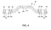
- FIG. 4 is a cross-sectional view illustrating a cross section taken along a line B-B in FIG. 1 .
- the members other than the bracket, the capsule and the shock absorbing mechanism are omitted in the illustration.
- FIG. 5A is a plan view of the shock absorbing mechanism 40.
- FIG. 5B is a side view when the shock absorbing mechanism 40 is viewed from the axial direction of the upper column tube 21.
- the shock absorbing mechanism 40 includes a bracket fixing portion 41, a pair of capsule fixing portions 42, and a breakable portion 43 that are integrally molded by resin.
- the bracket fixing portion 41 includes a projection portion 41a to be fitted to the depressed portion 35b of the bracket 35.
- the capsule fixing portion 42 includes a through hole 42a that has an inner circumference to be fitted to an outer circumference of the raised portion 34c of the capsule 34.
- the breakable portion 43 connects the bracket fixing portion 41 to the capsule fixing portion 42.
- the bracket fixing portion 41 is integrally fixed to the bracket 35.
- the capsule fixing portion 42 is integrally fixed to the capsule 34. It should be noted that although FIG. 5A exemplifies three strips for connecting the capsule fixing portion 42 to the bracket fixing portion 41 as the breakable portion 43, the number of strips is not limited to this. Any number can appropriately be set in accordance with desired breaking strength.
- the shock absorbing mechanism 40 When the shock absorbing mechanism 40 is fitted onto the bracket 35 and the capsule 34, the shock absorbing mechanism 40 is arranged from one capsule 34 to the other capsule 34 via the bracket 35. For this reason, the relative movement thereof in the axial direction of the upper column tube 21 is restricted.
- the upper shaft 11 and the upper column tube 21 integrally move in the axial direction so that the guide pin 53 moves until the guide pin 53 comes into contact with a terminating end of the guide hole 51 b (a stroke end of the telescopic mechanism).
- the load described above also acts on the bracket 35 from the upper column tube 21 via the column bracket 51 and the support bracket 52. When the load acts on the bracket 35, the bracket 35 attempts to move in a direction to be pulled out from the capsule 34, that is, the opposite direction with respect to the steering wheel 8.
- the capsule fixing portion 42 fixed to the capsule 34 and the bracket fixing portion 41 fixed to the bracket 35 move relative to each other to break the breakable portion 43. Accordingly, in a case where the excessive load acts on the steering wheel 8 at the time of the vehicle collision, the upper column tube 21 and the upper shaft 11 move with respect to the vehicle body to absorb shock energy applied to the upper shaft 11.
- the shock absorbing mechanism 40 that is broken to absorb the shock energy at the time of the vehicle collision includes: the bracket fixing portion 41 fitted to the bracket 34; the capsule fixing portion 42 fitted to the capsule 34; and the breakable portion 43 that connects the bracket fixing portion 41 to the capsule fixing portion 42. Accordingly, since the shock absorbing mechanism 40 can easily be mounted only by fitting the shock absorbing mechanism 40 to the bracket 35 and the capsule 34, it is possible to manufacture the electric power steering device 100 that includes the shock absorbing mechanism 40 without requiring the operator to be skilled.
- the capsule fixing portion 42 is fixed to the capsule 34 by fitting the through hole 42a of the capsule fixing portion 42 to the raised portion 34c of the capsule 34, it is possible to fix the shock absorbing mechanism 40 to the capsule 34 with a simple structure.
- the capsule fixing portion 42 is fixed by the bolt for fixing the capsule 34 to the vehicle body together, it is possible to prevent the capsule fixing portion 42 from being dropped off more reliably.
- the shock absorbing mechanism 40 is made of resin and the bracket fixing portion 41, the capsule fixing portion 42 and the breakable portion 43 are integrally molded, it is possible to reduce a manufacturing cost of the shock absorbing mechanism 40.
- the breakable portion 43 is constructed as the three strips for connecting the capsule fixing portion 42 to the bracket fixing portion 41, it is possible to break not the capsule fixing portion 42 or the bracket fixing portion 41 but the breakable portion 43 during the breaking more reliably. In addition, it is possible to appropriately set the breaking strength in accordance with the number of strips.
- the present invention can be applied to a hydraulic power steering device.
- the present invention can also be applied to a steering device that does not assist a steering force to be applied to the steering wheel 8 by the driver.
- shock absorbing mechanism 40 is made of resin in the embodiment described above, he shock absorbing mechanism 40 may be made of any other material.
- a plurality of hook portions 34d may be provided.
- the hook portion 34d is provided so as to extend upward (upward in FIG. 6A ) from an end surface of the capsule 34 on the bracket 35 side.
- the hook portions 34d are integrally formed as a part of the capsule 34. An interval between the adjacent hook portions 34d is set to the extent that the hook portion 34d and the breakable portion 43 of the shock absorbing mechanism 40 do not interfere with each other.
- a hook portion may be disposed at the bracket 35 in place of the capsule 34.
- the hook portion is provided so as to extend upward from a portion between the capsule 34 and the bracket fixing portion 41 on the bracket 35.
- the shock absorbing mechanism 40 which is fitted to the respective bracket 35 and capsule 34 that move relative to each other at the time of a vehicle collision, is broken at the time of the vehicle collision to perform shock absorbing.
- any other shock absorbing mechanism may be combined.
- the following configuration for performing shock absorbing may be combined. Namely, serrations are formed in both an outer circumference of the lower shaft 12 and an inner circumference of the upper shaft 11.
- the lower shaft 12 is formed in a taper shape to have an outer diameter that becomes larger toward the lower side in the axial direction.
- the serrations at both members are plastic-deformed or shear-deformed due to the relative movement between the lower shaft 12 and the upper shaft 11, thereby performing shock absorbing.
- the following configuration for performing shock absorbing may be combined. Namely, the upper column tube 21 side and the lower column tube 22 side are coupled together by an S-shaped plate. Shock absorbing is performed by stroking or drawing the S-shaped plate while moving the upper column tube 21 and the lower column tube 22 relatively to each other at the time of a vehicle collision.
Applications Claiming Priority (2)
| Application Number | Priority Date | Filing Date | Title |
|---|---|---|---|
| JP2012195171A JP5894888B2 (ja) | 2012-09-05 | 2012-09-05 | ステアリング装置 |
| PCT/JP2013/073624 WO2014038529A1 (fr) | 2012-09-05 | 2013-09-03 | Dispositif de direction |
Publications (2)
| Publication Number | Publication Date |
|---|---|
| EP2868549A1 true EP2868549A1 (fr) | 2015-05-06 |
| EP2868549A4 EP2868549A4 (fr) | 2016-03-23 |
Family
ID=50237138
Family Applications (1)
| Application Number | Title | Priority Date | Filing Date |
|---|---|---|---|
| EP13835917.9A Withdrawn EP2868549A4 (fr) | 2012-09-05 | 2013-09-03 | Dispositif de direction |
Country Status (5)
| Country | Link |
|---|---|
| US (1) | US9359001B2 (fr) |
| EP (1) | EP2868549A4 (fr) |
| JP (1) | JP5894888B2 (fr) |
| CN (1) | CN104602985B (fr) |
| WO (1) | WO2014038529A1 (fr) |
Families Citing this family (6)
| Publication number | Priority date | Publication date | Assignee | Title |
|---|---|---|---|---|
| US9988070B2 (en) * | 2014-02-27 | 2018-06-05 | Kyb Corporation | Steering device |
| JP6263415B2 (ja) * | 2014-02-27 | 2018-01-17 | Kyb株式会社 | ステアリング装置 |
| JP5975199B1 (ja) * | 2015-01-14 | 2016-08-23 | 日本精工株式会社 | ステアリング装置 |
| JP2017124715A (ja) * | 2016-01-13 | 2017-07-20 | 株式会社ショーワ | 操舵装置 |
| JP7157734B2 (ja) * | 2017-03-28 | 2022-10-20 | 株式会社山田製作所 | ステアリング装置 |
| JP7006309B2 (ja) * | 2018-01-25 | 2022-01-24 | 株式会社ジェイテクト | ステアリング装置 |
Family Cites Families (22)
| Publication number | Priority date | Publication date | Assignee | Title |
|---|---|---|---|---|
| GB1238060A (fr) * | 1968-12-20 | 1971-07-07 | ||
| US4117741A (en) * | 1976-12-01 | 1978-10-03 | Honda Giken Kogyo Kabushiki Kaisha | Collapsible steering column |
| JPS5946827B2 (ja) * | 1978-02-06 | 1984-11-15 | 光洋精工株式会社 | ステアリングコラム支持装置 |
| JP3471061B2 (ja) * | 1994-02-04 | 2003-11-25 | 光洋精工株式会社 | 衝撃吸収式ステアリング装置 |
| US5899116A (en) | 1997-12-08 | 1999-05-04 | General Motors Corporation | Connection for energy-absorbing steering column |
| US6086486A (en) * | 1998-05-04 | 2000-07-11 | Adjustotee Llc | Adjustable practice tee |
| JP3843234B2 (ja) * | 2001-12-04 | 2006-11-08 | 株式会社ジェイテクト | 衝撃吸収ステアリング装置 |
| WO2004101345A2 (fr) * | 2003-05-14 | 2004-11-25 | Toyota Jidosha Kabushiki Kaisha | Appareil de direction amortisseur |
| DE602006003460D1 (de) * | 2005-03-28 | 2008-12-18 | Fuji Kiko Kk | Lenksäule für ein Fahrzeug |
| JP2007076613A (ja) * | 2005-09-16 | 2007-03-29 | Toyota Motor Corp | ステアリングコラムの支持構造 |
| KR101065895B1 (ko) * | 2007-03-30 | 2011-09-19 | 주식회사 만도 | 충격 흡수장치를 구비한 자동차의 조향컬럼 |
| CN101456428A (zh) * | 2007-12-14 | 2009-06-17 | 中顺汽车控股有限公司 | 汽车转向柱总成结构 |
| JP5181668B2 (ja) | 2007-12-27 | 2013-04-10 | 日本精工株式会社 | ステアリング装置 |
| CN102438877B (zh) * | 2010-08-04 | 2013-12-25 | 日本精工株式会社 | 转向装置 |
| CN201721497U (zh) * | 2010-08-20 | 2011-01-26 | 株洲易力达机电有限公司 | 塑料定位保险块结构 |
| US9004534B2 (en) * | 2010-10-15 | 2015-04-14 | Nsk Ltd. | Steering apparatus for an automobile |
| US8733793B2 (en) * | 2010-10-15 | 2014-05-27 | Nsk, Ltd. | Steering column support apparatus |
| WO2012060193A1 (fr) * | 2010-11-02 | 2012-05-10 | 日本精工株式会社 | Dispositif d'assistance de colonne de direction |
| US8523228B2 (en) * | 2010-11-15 | 2013-09-03 | Nsk Ltd. | Steering column support apparatus |
| CN202213615U (zh) * | 2011-07-22 | 2012-05-09 | 浙江吉利汽车研究院有限公司 | 压溃防扭转的转向管柱 |
| JP5626164B2 (ja) * | 2011-07-26 | 2014-11-19 | 日本精工株式会社 | ステアリングコラム用支持装置 |
| WO2013069340A1 (fr) * | 2011-11-07 | 2013-05-16 | 日本精工株式会社 | Appareil de direction |
-
2012
- 2012-09-05 JP JP2012195171A patent/JP5894888B2/ja not_active Expired - Fee Related
-
2013
- 2013-09-03 US US14/419,243 patent/US9359001B2/en not_active Expired - Fee Related
- 2013-09-03 WO PCT/JP2013/073624 patent/WO2014038529A1/fr active Application Filing
- 2013-09-03 CN CN201380046217.XA patent/CN104602985B/zh not_active Expired - Fee Related
- 2013-09-03 EP EP13835917.9A patent/EP2868549A4/fr not_active Withdrawn
Also Published As
| Publication number | Publication date |
|---|---|
| WO2014038529A1 (fr) | 2014-03-13 |
| US9359001B2 (en) | 2016-06-07 |
| EP2868549A4 (fr) | 2016-03-23 |
| CN104602985A (zh) | 2015-05-06 |
| JP5894888B2 (ja) | 2016-03-30 |
| JP2014051129A (ja) | 2014-03-20 |
| US20150291204A1 (en) | 2015-10-15 |
| CN104602985B (zh) | 2016-09-07 |
Similar Documents
| Publication | Publication Date | Title |
|---|---|---|
| US9359001B2 (en) | Steering device | |
| US9533699B2 (en) | Steering device | |
| EP2366602B1 (fr) | Dispositif de direction | |
| EP2923922B1 (fr) | Dispositif de direction | |
| EP2923919B1 (fr) | Dispositif de direction | |
| EP2617625B1 (fr) | Dispositif de direction | |
| US20120318092A1 (en) | Steering apparatus | |
| EP2602170B1 (fr) | Appareil de direction | |
| JP5375996B2 (ja) | ステアリング装置 | |
| CN108528518B (zh) | 转向装置 | |
| WO2015129454A1 (fr) | Dispositif de direction | |
| US20170057535A1 (en) | Electronic release module linkage assembly for vehicle steering column | |
| US20170057536A1 (en) | Electronic release linkage with collapsible link member for vehicle steering column | |
| JP6313996B2 (ja) | ステアリング装置 | |
| JP6313997B2 (ja) | ステアリング装置 | |
| JP6378897B2 (ja) | ステアリング装置 | |
| JP6263415B2 (ja) | ステアリング装置 | |
| JP2005238894A (ja) | ステアリング装置 | |
| JP2004230953A (ja) | ステアリング装置 | |
| JP2014233987A (ja) | ステアリングコラム装置 | |
| KR101278848B1 (ko) | 자동차의 조향컬럼 | |
| JP2012006550A (ja) | 衝撃吸収式ステアリング装置 | |
| KR20110113869A (ko) | 자동차의 조향 컬럼 및 이를 구비하는 자동차의 조향장치 | |
| KR20130064313A (ko) | 틸트 또는 틸트 앤 텔레스코프 조향장치 및 이의 조립 방법 |
Legal Events
| Date | Code | Title | Description |
|---|---|---|---|
| PUAI | Public reference made under article 153(3) epc to a published international application that has entered the european phase |
Free format text: ORIGINAL CODE: 0009012 |
|
| 17P | Request for examination filed |
Effective date: 20150127 |
|
| AK | Designated contracting states |
Kind code of ref document: A1 Designated state(s): AL AT BE BG CH CY CZ DE DK EE ES FI FR GB GR HR HU IE IS IT LI LT LU LV MC MK MT NL NO PL PT RO RS SE SI SK SM TR |
|
| AX | Request for extension of the european patent |
Extension state: BA ME |
|
| DAX | Request for extension of the european patent (deleted) | ||
| RAP1 | Party data changed (applicant data changed or rights of an application transferred) |
Owner name: KYB CORPORATION |
|
| RA4 | Supplementary search report drawn up and despatched (corrected) |
Effective date: 20160218 |
|
| RIC1 | Information provided on ipc code assigned before grant |
Ipc: B62D 1/19 20060101AFI20160212BHEP Ipc: B60R 21/05 20060101ALI20160212BHEP |
|
| 17Q | First examination report despatched |
Effective date: 20170324 |
|
| GRAP | Despatch of communication of intention to grant a patent |
Free format text: ORIGINAL CODE: EPIDOSNIGR1 |
|
| INTG | Intention to grant announced |
Effective date: 20190411 |
|
| RIN1 | Information on inventor provided before grant (corrected) |
Inventor name: CHIBA, SHUHEI |
|
| STAA | Information on the status of an ep patent application or granted ep patent |
Free format text: STATUS: THE APPLICATION IS DEEMED TO BE WITHDRAWN |
|
| 18D | Application deemed to be withdrawn |
Effective date: 20190822 |