EP2867541B1 - Photovoltaic frame fastener - Google Patents
Photovoltaic frame fastener Download PDFInfo
- Publication number
- EP2867541B1 EP2867541B1 EP13734301.8A EP13734301A EP2867541B1 EP 2867541 B1 EP2867541 B1 EP 2867541B1 EP 13734301 A EP13734301 A EP 13734301A EP 2867541 B1 EP2867541 B1 EP 2867541B1
- Authority
- EP
- European Patent Office
- Prior art keywords
- fastener
- frame
- strut
- wings
- tongue
- Prior art date
- Legal status (The legal status is an assumption and is not a legal conclusion. Google has not performed a legal analysis and makes no representation as to the accuracy of the status listed.)
- Active
Links
- 238000000034 method Methods 0.000 claims description 7
- 230000015572 biosynthetic process Effects 0.000 claims description 5
- 238000005755 formation reaction Methods 0.000 claims description 5
- 238000003780 insertion Methods 0.000 claims description 5
- 239000011521 glass Substances 0.000 claims description 4
- 229910052751 metal Inorganic materials 0.000 claims description 3
- 239000002184 metal Substances 0.000 claims description 3
- 238000010276 construction Methods 0.000 description 7
- 238000009434 installation Methods 0.000 description 4
- 230000002093 peripheral effect Effects 0.000 description 4
- 239000000463 material Substances 0.000 description 3
- 229910000831 Steel Inorganic materials 0.000 description 2
- 238000013459 approach Methods 0.000 description 2
- 230000006835 compression Effects 0.000 description 2
- 238000007906 compression Methods 0.000 description 2
- 230000006378 damage Effects 0.000 description 2
- 230000037431 insertion Effects 0.000 description 2
- 238000004519 manufacturing process Methods 0.000 description 2
- 239000010959 steel Substances 0.000 description 2
- 229910000788 1018 steel Inorganic materials 0.000 description 1
- 241000276495 Melanogrammus aeglefinus Species 0.000 description 1
- 229910000639 Spring steel Inorganic materials 0.000 description 1
- 229910052782 aluminium Inorganic materials 0.000 description 1
- XAGFODPZIPBFFR-UHFFFAOYSA-N aluminium Chemical compound [Al] XAGFODPZIPBFFR-UHFFFAOYSA-N 0.000 description 1
- 239000011324 bead Substances 0.000 description 1
- 239000011248 coating agent Substances 0.000 description 1
- 238000000576 coating method Methods 0.000 description 1
- 230000014759 maintenance of location Effects 0.000 description 1
- 229910001220 stainless steel Inorganic materials 0.000 description 1
- 239000010935 stainless steel Substances 0.000 description 1
- 239000011800 void material Substances 0.000 description 1
Images


Classifications
-
- H—ELECTRICITY
- H02—GENERATION; CONVERSION OR DISTRIBUTION OF ELECTRIC POWER
- H02S—GENERATION OF ELECTRIC POWER BY CONVERSION OF INFRARED RADIATION, VISIBLE LIGHT OR ULTRAVIOLET LIGHT, e.g. USING PHOTOVOLTAIC [PV] MODULES
- H02S20/00—Supporting structures for PV modules
- H02S20/20—Supporting structures directly fixed to an immovable object
- H02S20/22—Supporting structures directly fixed to an immovable object specially adapted for buildings
- H02S20/23—Supporting structures directly fixed to an immovable object specially adapted for buildings specially adapted for roof structures
-
- H—ELECTRICITY
- H02—GENERATION; CONVERSION OR DISTRIBUTION OF ELECTRIC POWER
- H02S—GENERATION OF ELECTRIC POWER BY CONVERSION OF INFRARED RADIATION, VISIBLE LIGHT OR ULTRAVIOLET LIGHT, e.g. USING PHOTOVOLTAIC [PV] MODULES
- H02S20/00—Supporting structures for PV modules
-
- F—MECHANICAL ENGINEERING; LIGHTING; HEATING; WEAPONS; BLASTING
- F24—HEATING; RANGES; VENTILATING
- F24S—SOLAR HEAT COLLECTORS; SOLAR HEAT SYSTEMS
- F24S25/00—Arrangement of stationary mountings or supports for solar heat collector modules
- F24S25/60—Fixation means, e.g. fasteners, specially adapted for supporting solar heat collector modules
- F24S25/63—Fixation means, e.g. fasteners, specially adapted for supporting solar heat collector modules for fixing modules or their peripheral frames to supporting elements
- F24S25/634—Clamps; Clips
-
- F—MECHANICAL ENGINEERING; LIGHTING; HEATING; WEAPONS; BLASTING
- F16—ENGINEERING ELEMENTS AND UNITS; GENERAL MEASURES FOR PRODUCING AND MAINTAINING EFFECTIVE FUNCTIONING OF MACHINES OR INSTALLATIONS; THERMAL INSULATION IN GENERAL
- F16B—DEVICES FOR FASTENING OR SECURING CONSTRUCTIONAL ELEMENTS OR MACHINE PARTS TOGETHER, e.g. NAILS, BOLTS, CIRCLIPS, CLAMPS, CLIPS OR WEDGES; JOINTS OR JOINTING
- F16B7/00—Connections of rods or tubes, e.g. of non-circular section, mutually, including resilient connections
- F16B7/04—Clamping or clipping connections
- F16B7/044—Clamping or clipping connections for rods or tubes being in angled relationship
- F16B7/0446—Clamping or clipping connections for rods or tubes being in angled relationship for tubes using the innerside thereof
- F16B7/0473—Clamping or clipping connections for rods or tubes being in angled relationship for tubes using the innerside thereof with hook-like parts gripping, e.g. by expanding, behind the flanges of a profile
-
- F—MECHANICAL ENGINEERING; LIGHTING; HEATING; WEAPONS; BLASTING
- F24—HEATING; RANGES; VENTILATING
- F24S—SOLAR HEAT COLLECTORS; SOLAR HEAT SYSTEMS
- F24S25/00—Arrangement of stationary mountings or supports for solar heat collector modules
- F24S25/60—Fixation means, e.g. fasteners, specially adapted for supporting solar heat collector modules
- F24S2025/6003—Fixation means, e.g. fasteners, specially adapted for supporting solar heat collector modules by clamping
-
- F—MECHANICAL ENGINEERING; LIGHTING; HEATING; WEAPONS; BLASTING
- F24—HEATING; RANGES; VENTILATING
- F24S—SOLAR HEAT COLLECTORS; SOLAR HEAT SYSTEMS
- F24S25/00—Arrangement of stationary mountings or supports for solar heat collector modules
- F24S25/60—Fixation means, e.g. fasteners, specially adapted for supporting solar heat collector modules
- F24S2025/6004—Fixation means, e.g. fasteners, specially adapted for supporting solar heat collector modules by clipping, e.g. by using snap connectors
-
- Y—GENERAL TAGGING OF NEW TECHNOLOGICAL DEVELOPMENTS; GENERAL TAGGING OF CROSS-SECTIONAL TECHNOLOGIES SPANNING OVER SEVERAL SECTIONS OF THE IPC; TECHNICAL SUBJECTS COVERED BY FORMER USPC CROSS-REFERENCE ART COLLECTIONS [XRACs] AND DIGESTS
- Y02—TECHNOLOGIES OR APPLICATIONS FOR MITIGATION OR ADAPTATION AGAINST CLIMATE CHANGE
- Y02B—CLIMATE CHANGE MITIGATION TECHNOLOGIES RELATED TO BUILDINGS, e.g. HOUSING, HOUSE APPLIANCES OR RELATED END-USER APPLICATIONS
- Y02B10/00—Integration of renewable energy sources in buildings
- Y02B10/10—Photovoltaic [PV]
-
- Y—GENERAL TAGGING OF NEW TECHNOLOGICAL DEVELOPMENTS; GENERAL TAGGING OF CROSS-SECTIONAL TECHNOLOGIES SPANNING OVER SEVERAL SECTIONS OF THE IPC; TECHNICAL SUBJECTS COVERED BY FORMER USPC CROSS-REFERENCE ART COLLECTIONS [XRACs] AND DIGESTS
- Y02—TECHNOLOGIES OR APPLICATIONS FOR MITIGATION OR ADAPTATION AGAINST CLIMATE CHANGE
- Y02E—REDUCTION OF GREENHOUSE GAS [GHG] EMISSIONS, RELATED TO ENERGY GENERATION, TRANSMISSION OR DISTRIBUTION
- Y02E10/00—Energy generation through renewable energy sources
- Y02E10/40—Solar thermal energy, e.g. solar towers
- Y02E10/47—Mountings or tracking
-
- Y—GENERAL TAGGING OF NEW TECHNOLOGICAL DEVELOPMENTS; GENERAL TAGGING OF CROSS-SECTIONAL TECHNOLOGIES SPANNING OVER SEVERAL SECTIONS OF THE IPC; TECHNICAL SUBJECTS COVERED BY FORMER USPC CROSS-REFERENCE ART COLLECTIONS [XRACs] AND DIGESTS
- Y02—TECHNOLOGIES OR APPLICATIONS FOR MITIGATION OR ADAPTATION AGAINST CLIMATE CHANGE
- Y02E—REDUCTION OF GREENHOUSE GAS [GHG] EMISSIONS, RELATED TO ENERGY GENERATION, TRANSMISSION OR DISTRIBUTION
- Y02E10/00—Energy generation through renewable energy sources
- Y02E10/50—Photovoltaic [PV] energy
-
- Y—GENERAL TAGGING OF NEW TECHNOLOGICAL DEVELOPMENTS; GENERAL TAGGING OF CROSS-SECTIONAL TECHNOLOGIES SPANNING OVER SEVERAL SECTIONS OF THE IPC; TECHNICAL SUBJECTS COVERED BY FORMER USPC CROSS-REFERENCE ART COLLECTIONS [XRACs] AND DIGESTS
- Y10—TECHNICAL SUBJECTS COVERED BY FORMER USPC
- Y10T—TECHNICAL SUBJECTS COVERED BY FORMER US CLASSIFICATION
- Y10T403/00—Joints and connections
- Y10T403/54—Flexible member is joint component
Definitions
- the present disclosure relates generally to a fastener and more particularly to a photovoltaic frame fastener.
- peripheral mounting frames holding solar or photovoltaic panels are mounted to a supporting structure on a building roof or on the land through use of threaded fasteners and multi-piece brackets.
- Exemplary traditional devices are disclosed in U.S. Patent No. 7,758,011 entitled “Adjustable Mounting Assembly for Standing Seam Panels” which issued to Haddock on July 20, 2010, and U.S. Patent No. 6,105,317 entitled “Mounting System For Installing an Array of Solar Battery Modules of a Panel-Like Configuration on a Roof” which issued to Tomiuchi et al. on August 22, 2000.
- a photovoltaic frame fastener is provided according to claim 1 and a method of attaching the solar panel according to claim 12.
- a photovoltaic frame attachment apparatus includes a strut or rail defining a generally U-shaped channel and a snap-in clip or fastener.
- a single-piece fastener includes a strut-engaging surface, at least one flexible wing matable with an opening in a strut, a flexible tongue internally projecting in a central manner from a top wall of a body, and a slot adapted to receive a portion of a photovoltaic panel frame.
- the central tongue has at least one formation for securing the frame in the slot.
- Yet another aspect of a photovoltaic frame fastener includes laterally projecting tabs abutting against a top of a strut.
- a bifurcated tongue is employed in an additional aspect.
- a method of attaching a photovoltaic frame to an elongated structure is also provided.
- the present photovoltaic frame fastener is advantageous over traditional devices.
- the one-piece nature of the present fastener is inexpensive and fast to manufacture, install and remove.
- the present fastener is suitable for pre-assembly to the frame offsite or at a manufacturing plant, thereby improving quality and reducing assembly cost.
- the present fastener advantageously hides the snap-in wing sections securing the frame and strut, thereby making theft and vandalism difficult.
- the retention forces are direction in-line thereby advantageously reducing torsion on the fastener which achieves a more secure attachment with less stress on the fastener, frame and solar panel, and requiring lower installation force.
- a more secure attachment is realized by reducing side-to-side and/or front-to-back tilting, while also preventing over-insertion of a fastener into a strut opening.
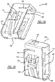
- a first embodiment of a photovoltaic frame fastener assembly 10 includes elongated and rigid rails or struts 12, solar or photovoltaic panel modules 14, and fasteners 16. Struts 12 are mounted to vertical legs 18 attached to land or ground 20 in one configuration. In another configuration, struts 12 are bolted onto a roof clamp or other structure on a roof or side of a building 22.
- Each photovoltaic module 14 includes a chemically coated glass photovoltaic panel 24 and an adhesively attached, peripheral metallic frame 26. Glass photovoltaic panel 24 and metallic frame 26 are provided as a pre-assembled unit or may be provided as separate units to the installation site.
- strut 12 has a uniform and generally U-shaped cross-section as defined by upstanding sidewalls 30 joined by a bottom wall 32.
- a reverse-turned wall 34 extends from a top end of each sidewall 30 and terminates in a downwardly directed edge 36.
- Downwardly directed edge 36 provides a folded-over region of upstanding sidewalls 30 and as detailed below provide attachment points for wings of fasteners 16.
- An elongated channel or opening 38 is defined between reverse turn walls 34.
- Optional mounting holes 40 are provided in bottom wall 32 to allow for securing of strut 12 to a building attachment, bolt upwardly projecting from a standing seam roof clamp, or ground-based support.
- Strut 12 is stamped or rolled from aluminum or steel.
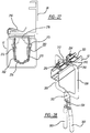
- fastener 16 includes a body 50, a pair of flexible wings 52, and four rigid tabs 54.
- Body 50 includes a top wall 56, a pair of spaced apart side walls 58 and tapered lead-in walls 60.
- the walls of body 50 and wings 52 define peripheral edges 62 that allow for hollow open access at ends thereof.
- lead-in walls 60 cross and overlap each other adjacent distal edges thereof.
- a pair of aligned and elongated openings or slots 68 are disposed in an upper area of body 50 above at least some of tabs 54.
- Each slot 68 has an openly accessible end and they both receive a flat segment of metallic frame 26 inserted therein to secure photovoltaic module 14 to fastener 16.
- a flexible tongue member 80 is downwardly and diagonally bent from an inside of top wall 56 of fastener 16.
- a distal edge of tongue 80 includes multiple, preferably two, generally pointed formations 82 separated by a recess or valley 84. Formations 82 gouge or score into a top surface of frame 26 to secure frame 26 within slots 68 of fastener 16.
- the diagonal and flexible nature of tongue 80 allows for low effort installation of frame 26 into slots 68 but significantly greater (at least four times) removal force.
- Tongue 80 is centrally inboard of all peripheral fastener edges 62 adjacent to a central hole 86 in top wall 56.
- An inwardly curved finger 90 upwardly projects from a top section of each wing 52.
- Finger 90 has a smaller width (the width being in the elongated direction of strut 12) than does the adjacent wing 52.
- Each wing 52 further has an offset angled step 92 at an apex, defining a thickness dimension of the collective wings.
- Barbs or outwardly and localized arms 94 are located on the lateral edges adjacent each step 92 to more securly engage downturned edges 36 of strut.
- Fastener 100 includes a top wall 102, side walls 104 and tapered lead-in walls 106 like with the prior embodiment fastener 16. Furthermore, a frame receiving slot 108 is located within each side wall 104 and a flexible and bifurcated tongue 110 is downwardly bent from top wall 102 like with the prior embodiment. At least two, and more preferably four, rigid tabs 112 outwardly extend in a generally parallel manner to each other and perpendicular from each associated side wall 104.
- Tabs 112 like with the prior embodiment, abut against an outside surface of strut 12 adjacent the opening therein, to deter tilting of the fastener and also to prevent over-insertion of the fastener too far into the strut during installation.
- Each tab 112 has a greater longitudinal dimension a than a width dimension b, in order to increase the longitudinal rigidity and stiffness of the tab.
- the present fastener 100 has a pair of flexible wings 120 which are outwardly bent from side walls 104 adjacent lead-in walls 106, but longitudinally directly below slots 108.
- This alignment advantageously reduces undesired torque imparted on fastener 100 due to a lateral offset of slots 68 (see Figure 4 ) versus wings 52 of the prior embodiment fastener.
- the present fastener 100 is more compact and the wings 120 are better hidden by the attached solar panel module and frame 26 thereabove.
- a longitudinal dimension L is greater than both a width W and a total nominal thickness T, for this embodiment.
- a finger 126 centrally extends from an upper edge of each wing 120 generally between a pair of adjacent tabs 112. Each finger 126 has an outwardly curved distal end opposite the corresponding step 128 of each wing. Moreover, finger 126 has a smaller lateral width as compared to adjacent wing 120 in order to allow for material size savings of a sheet metal blank 130 from which fastener 100 is stamped and bent as a single, metallic piece.
- a stiffening rib or bead 132 is also provided along a generally flat outwardly angled section of each wing 120 to provide compressive strength to resist inadvertent disassembly from strut 12 after the wings have been snapped into engagement with return edge of the strut during assembly. Fastener 100 resists at least 100 pounds of pullout force from strut 12 without destruction.
- Fasteners 16 and 100 are preferably stamped from a Magni coated and austemper heat treated spring steel of type SAE 1050-1065, with a finish hardness of 44-51 Rc, and a sheet thickness of 1.0 nm, but alternately may be stamped from stainless steel.
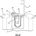
- Upper removal tool 150 is preferably a screwdriver having an enlarged handle 152, an enlongated rigid shaft 154 and a flat blade 154.
- the construction or service person initially inserts screwdriver tool 150 in a linear and lateral direction into the hollow opening of fastener 16 between the side walls and below the glass solar module. This may be either done from below the assembly as space allows, or after the fastener is removed from the strut as will be described in further detail hereinafter.
- Blade 154 is linearly and horizontally inserted between valley 84 (see Figure 6 ) and the segment of frame 26 that is within slots 68.
- a primary handle 192 is integrally formed as part of one jaw 172.
- a separate auxiliary handle 194 is coupled to the other jaw 172 via one or more pivots 196.
- a camming link 198 pivotally couples the handles together as does a biasing spring 200.
- An adjustment screw 202 is threadably received within primary handle 192 for setting the adjusted position of camming link 198.
- a release handle 204 is pivotally coupled to handle 194 for releasing a clamped and locked state of tool 170.
- the handle and locking mechanism work in accordance with U.S. Patent No. 8,056,451 entitled "Locking Pliers" which issued to Chervenak et al. on November 15, 2011, which is incorporated by reference herein.
- This tool embodiment can be used from below the fastener and strut as further discussed hereinafter, or is well suited for engaging laterally offset wings 52 (see Figure 3 ) of fastener 16 from above and between adjacent photovoltaic panel modules 14.
- the construction or service person initially approaches fastener 100 (by way of non-limiting example) from below strut 12.
- the person thereafter essentially surrounds a cross-section of strut 12 by jaws 222 as tips 230 make initial contact with fingers 126 (as can best be observed in Figures 14 and 16 ) accessible above the upper surface of strut 12.
- the construction person fully squeezes together handles 224 and 226 such that the camming link will put the tool in a locking and fully clamped position, which causes tips 230 of tool 220 to be in their fully compressed position (as adjusted by adjustment screw 240).
- tips 230 inwardly compress fingers 126 and the attached wings 120 toward each other and the fastener centerline, such that the wings can thereafter be longitudinally and linearly pulled free of strut 12 through the upper opening therein while staying engaged by tool 220.
- release handle 228 is pulled toward auxiliary handle 226 to release the locking mechanism and thereby disengage tool 220 from fastener 100.
- lower removal tool 220 is also advantageous by allowing for hands-free wing compression after the tool clamping position has been set; this is especially advantageous when many of these tools simultaneously engage and compress multiple fasteners for the same solar panel module whereafter the construction person can then use both of this hands for pulling up on the frame to remove all of the fasteners from the strut at the same time.
- Lower removal tool 220 is designed to not damage the fasteners such that they can be repeatedly reused.
- the lower removal tools are preferably cast or stamped from steel, although other materials can be employed.
- Grounding clip 252 includes a pair of spaced apart clamps 254 and 256, an upper bridge 258 and a mounting section 260. Each clamp has a generally C-shape, thereby creating an openly accessible receptacle therebetween. Furthermore, a lead-in wall 262 upwardly and outwardly angles away from each clamp to ease insertion of a flat lateral flange segment of frame 26 therein during assembly. If used for grounding, a pair of pointed barbs 264 internally project from each upper section of clamps 254 and 256.
- Each barb 264 cuts into and gouges the adjacent surface of frame 26 to scrape off the anodized coating thereat. This provides multiple satisfactory electrical grounding paths between the base material of the frame and the clip. This can be achieved by the simple linear insertion of the clamps of the clip onto the flange of the frame without the need for rotation or a threaded attachment. Alternately, the same fastener clip 252 can be used in a non-electrical grounding manner if barbs 264 are omitted.
- Mounting section 260 includes side walls 270 and flexible wings 272. Each wing 272 is flexibly attached adjacent an inwardly tapered distal end 274 and is linearly snap-fit into the opening in strut 12 when installed. A finger 276 projects upwardly from each wing proud of strut. Furthermore, an offset step is located along a longitudinal length of each wing located closer to the finger than the distal end.
- This embodiment removal tool 250 has a pair of generally cylindrical and longitudinally elongated handles 300 rotatably coupled together at pivot 302.
- a hinge 304 couples each handle 300 to a corresponding jaw 306.
- a flat and longitudinally thinner tip 310 laterally projects inward from each end of jaw 306 for contacting against and compressing upstanding fingers 276 from the expanded strut-engaging position to an inwardly compressed position 276' whereafter the construction person can linearly remove fastener 252 from strut 12. Since jaws 306 are stamped from 1018 steel, a twist 312 is stamped between tips 310 and jaws 306.
- Lower removal tool 250 has a scissor handle and pivot arrangement to move jaws 306, but without a locking feature.
- this third embodiment lower removal tool 250 is also well suited for top down access within a gap between a pair of installed solar modules, including frames 26. Tips 310 then contact against and compress fingers 90 and their associated wings of the first embodiment fastener 100. This approach is easiest for a roof-mounted assembly.
Landscapes
- Engineering & Computer Science (AREA)
- Architecture (AREA)
- Civil Engineering (AREA)
- Structural Engineering (AREA)
- Physics & Mathematics (AREA)
- Life Sciences & Earth Sciences (AREA)
- Sustainable Development (AREA)
- Sustainable Energy (AREA)
- Thermal Sciences (AREA)
- Chemical & Material Sciences (AREA)
- Combustion & Propulsion (AREA)
- Mechanical Engineering (AREA)
- General Engineering & Computer Science (AREA)
- Roof Covering Using Slabs Or Stiff Sheets (AREA)
- Photovoltaic Devices (AREA)
Priority Applications (1)
| Application Number | Priority Date | Filing Date | Title |
|---|---|---|---|
| PL13734301T PL2867541T3 (pl) | 2012-07-02 | 2013-06-27 | Łącznik ramy panelu fotowoltaicznego |
Applications Claiming Priority (2)
| Application Number | Priority Date | Filing Date | Title |
|---|---|---|---|
| US13/539,814 US9331629B2 (en) | 2012-07-02 | 2012-07-02 | Photovoltaic frame fastener |
| PCT/US2013/048131 WO2014008087A2 (en) | 2012-07-02 | 2013-06-27 | Photovoltaic frame fastener |
Publications (2)
| Publication Number | Publication Date |
|---|---|
| EP2867541A2 EP2867541A2 (en) | 2015-05-06 |
| EP2867541B1 true EP2867541B1 (en) | 2017-11-08 |
Family
ID=48746718
Family Applications (1)
| Application Number | Title | Priority Date | Filing Date |
|---|---|---|---|
| EP13734301.8A Active EP2867541B1 (en) | 2012-07-02 | 2013-06-27 | Photovoltaic frame fastener |
Country Status (13)
| Country | Link |
|---|---|
| US (1) | US9331629B2 (pt) |
| EP (1) | EP2867541B1 (pt) |
| JP (1) | JP6232424B2 (pt) |
| CN (1) | CN104603472B (pt) |
| CA (1) | CA2878219C (pt) |
| CY (1) | CY1119866T1 (pt) |
| DK (1) | DK2867541T3 (pt) |
| ES (1) | ES2657597T3 (pt) |
| MX (1) | MX355947B (pt) |
| PL (1) | PL2867541T3 (pt) |
| PT (1) | PT2867541T (pt) |
| WO (1) | WO2014008087A2 (pt) |
| ZA (1) | ZA201500231B (pt) |
Families Citing this family (55)
| Publication number | Priority date | Publication date | Assignee | Title |
|---|---|---|---|---|
| US11261897B2 (en) * | 2003-11-17 | 2022-03-01 | Mag Daddy, LLC | Structural fastener |
| US11784428B2 (en) * | 2018-08-20 | 2023-10-10 | Mag Daddy Llc | Structural fastener |
| US11815206B2 (en) * | 2004-09-16 | 2023-11-14 | Mag Daddy Llc | Structural fastener |
| US9911880B2 (en) | 2009-10-06 | 2018-03-06 | Solarcity Corporation | Method and apparatus for forming and mounting a photovoltaic array |
| US10054336B2 (en) | 2010-03-03 | 2018-08-21 | Robert M. M. Haddock | Photovoltaic module mounting assembly |
| US9611652B2 (en) | 2011-02-25 | 2017-04-04 | Dustin M. M. Haddock | Mounting device for building surfaces having elongated mounting slot |
| WO2013101597A1 (en) | 2011-12-29 | 2013-07-04 | Haddock Dustin M M | Mounting device for nail strip panels |
| US20130240008A1 (en) * | 2012-03-16 | 2013-09-19 | Christopher Baker | System and method for mounting photovoltaic modules |
| EP2972006B1 (en) | 2013-03-15 | 2020-02-12 | RMH Tech LLC | Slide fit mounting clip for installing photovoltaic modules |
| US9705447B2 (en) | 2013-03-28 | 2017-07-11 | Georgia Tech Research Corporation | Mounting clips for panel installation |
| CN104617855B (zh) * | 2015-01-14 | 2017-03-15 | 广西衍易新能源投资有限公司 | 一种太阳能光伏支架 |
| US10020773B2 (en) * | 2015-04-17 | 2018-07-10 | Solarcity Corporation | Photovoltaic mounting system |
| CA3070451C (en) * | 2015-05-26 | 2022-05-03 | Arcelormittal | Panel, assembly of panels, and associated roof |
| US10187006B2 (en) * | 2015-07-15 | 2019-01-22 | Solarcity Corporation | Wedge spring clip mounting system for photovoltaic modules |
| US9793852B2 (en) | 2015-07-15 | 2017-10-17 | Solarcity Corporation | Clamp and bowl mounting system for photovoltaic modules |
| US10663195B2 (en) | 2015-07-29 | 2020-05-26 | Ironridge, Inc. | Tile roof mount |
| US10720877B2 (en) * | 2016-02-25 | 2020-07-21 | Solarcity Corporation | Photovoltaic mounting system for solar tracker array |
| USD800057S1 (en) * | 2016-07-18 | 2017-10-17 | Hafenbahn Gmbh & Co. Kg | Solar panel mounting |
| WO2018023016A1 (en) | 2016-07-29 | 2018-02-01 | Haddock Dustin M M | Trapezoidal rib mounting bracket with flexible legs |
| FR3054862B3 (fr) * | 2016-08-04 | 2018-08-31 | A Raymond Et Cie | Agrafe de maintien de deux elements plans |
| WO2018039291A1 (en) * | 2016-08-23 | 2018-03-01 | Giga Solar Fpc, Inc. | Improved solar module mounting systems and processes thereof |
| DE202017105045U1 (de) * | 2016-10-07 | 2017-12-07 | Jing-Xin Solar Ltd. | Bodenhalterung |
| US10640980B2 (en) | 2016-10-31 | 2020-05-05 | Rmh Tech Llc | Metal panel electrical bonding clip |
| CN106452305B (zh) * | 2016-11-16 | 2018-11-23 | 海宁创源太阳能科技有限公司 | 一种太阳能电池板安装支架及其安装方法 |
| US10371185B2 (en) | 2017-01-09 | 2019-08-06 | David Lynn | Magnetically-controlled connectors and methods of use |
| CN106972823A (zh) * | 2017-05-23 | 2017-07-21 | 浙江晶科能源有限公司 | 一种光伏组件边框、光伏电池组件及其安装方法 |
| CN106992744A (zh) * | 2017-05-24 | 2017-07-28 | 朱国浩 | 一种太阳能电池板安装组件 |
| US10060460B1 (en) * | 2017-07-05 | 2018-08-28 | Brandon C. Winn | Precursor for a furring channel clip, furring channel clip formed therefrom, method of making a furring channel clip, and method of mounting a furring channel to a load bearing member |
| PT3695171T (pt) | 2017-10-09 | 2024-02-29 | Rmh Tech Llc | Montagem de calha com adaptador de montagem lateral invertível para aplicações de montagem direta e indireta |
| CN107888140A (zh) * | 2017-12-05 | 2018-04-06 | 罗有志 | 一种加强筋边框 |
| CN107979326B (zh) * | 2017-12-26 | 2024-04-19 | 浙江双宇电子科技有限公司 | 一种太阳能的安装机构 |
| CN107888141B (zh) * | 2017-12-26 | 2024-04-19 | 浙江双宇电子科技有限公司 | 一种太阳能边框的卡扣 |
| US10651786B2 (en) | 2018-01-08 | 2020-05-12 | David Lynn | Panel with magnetically-controlled connectors for attachment to a support member |
| CA3089838A1 (en) | 2018-02-01 | 2019-08-08 | Oldcastle Buildingenvelope, Inc. | Demountable wall system and method |
| MX2020009805A (es) | 2018-03-21 | 2020-10-14 | Rmh Tech Llc | Ensamble de montaje de modulo pv con acomodo de fijacion/montaje vertical. |
| FR3079890B1 (fr) | 2018-04-04 | 2020-04-03 | A. Raymond Et Cie | Agrafe de fixation pour chassis photovoltaique a montage par insertion puis coulissement dans une fente d’une paroi de support |
| US10971870B2 (en) | 2018-08-17 | 2021-04-06 | David Lynn | Connection interface for a panel and support structure |
| US11619324B2 (en) * | 2018-08-20 | 2023-04-04 | Mag Daddy, LLC | Structural fastener |
| AU2019397167B2 (en) | 2018-12-14 | 2023-04-06 | Rmh Tech Llc | Mounting device for nail strip panels |
| EP3670938A1 (en) | 2018-12-21 | 2020-06-24 | A. Raymond et Cie | Toolless slot fastener |
| US10622935B1 (en) * | 2019-04-06 | 2020-04-14 | Sunmodo Corporation | Rail-mounted bottom clamp for mounting solar panels to roofs and the like |
| CN113498578A (zh) * | 2020-02-07 | 2021-10-12 | 詹姆斯·袁 | 太阳能板和带有边缘连接器的轨道 |
| US11811358B2 (en) | 2020-02-11 | 2023-11-07 | Apa Solar, Llc | Solar module mounting system |
| US11258397B2 (en) | 2020-02-11 | 2022-02-22 | Ap Alternatives, Llc | Solar module mounting system |
| DE112021001674T5 (de) | 2020-03-16 | 2023-06-01 | Rmh Tech Llc | Befestigungsvorrichtung für ein Metalldach |
| US11041310B1 (en) | 2020-03-17 | 2021-06-22 | Rmh Tech Llc | Mounting device for controlling uplift of a metal roof |
| MX2023003020A (es) * | 2020-09-14 | 2023-04-10 | Array Tech Inc | Abrazadera de resorte para montaje de módulo fotovoltaico. |
| FR3118108B1 (fr) * | 2020-12-17 | 2022-11-11 | A Raymond Et Cie | Agrafe de maintien de deux elements plans, assemblage comprenant une telle agrafe |
| US11499315B1 (en) * | 2021-06-10 | 2022-11-15 | Harsoyo Lukito | Connectors for use in truss system |
| US11920355B2 (en) * | 2021-12-23 | 2024-03-05 | 0776425 B.C. Ltd. | Building material attachment devices, systems, and associated methods of manufacture and use |
| FR3134436B1 (fr) | 2022-04-06 | 2024-03-22 | A Raymond Et Cie | Kit d’attache d’un panneau pourvu d’une pièce de maintien et d’un élément de serrage, pièce de maintien et élément de serrage dudit kit d’attache |
| DE102022113986B3 (de) * | 2022-06-02 | 2023-10-12 | Hanwha Q Cells Gmbh | Befestigung für einen Photovoltaikmodulrahmen und Verfahren zu dessen Befestigung |
| WO2024000151A1 (en) * | 2022-06-28 | 2024-01-04 | A. Raymond Et Cie | Fastening clip |
| WO2024095028A1 (en) * | 2022-10-31 | 2024-05-10 | A. Raymond Et Cie | Fastening clip |
| US11770097B1 (en) | 2023-03-15 | 2023-09-26 | Sunmodo Corporation | Rail-attached bottom clamp for solar panels secured to roofs and building structures |
Citations (2)
| Publication number | Priority date | Publication date | Assignee | Title |
|---|---|---|---|---|
| DE202009004746U1 (de) * | 2009-04-28 | 2009-07-23 | Kumatec Sondermaschinenbau & Kunststoffverarbeitung Gmbh | Befestigungseinrichtung zum Fixieren eines Holmes oder einer Leiste an einem C-Profil |
| DE102010022556B3 (de) * | 2010-06-02 | 2011-06-30 | A. Raymond Et Cie S.C.S. | Vorrichtung zum Befestigen eines Solarmoduls |
Family Cites Families (92)
| Publication number | Priority date | Publication date | Assignee | Title |
|---|---|---|---|---|
| GB423385A (en) | 1933-10-31 | 1935-01-31 | London Electric Wire Company A | Improvements in or relating to earthing devices for use with electrical systems |
| AT290223B (de) | 1968-02-17 | 1971-03-15 | Bettermann Elektro Ohg | Reihenschelle |
| US3757268A (en) | 1971-11-04 | 1973-09-04 | Circle F Ind Inc | Self grounding receptacle |
| FR2163787A5 (pt) | 1971-12-01 | 1973-07-27 | Mangiarotti Angelo | |
| FR2209024A1 (pt) | 1972-12-04 | 1974-06-28 | Martin Lavigne Francis | |
| US3998018A (en) | 1975-03-31 | 1976-12-21 | Kaiser Cement & Gypsum Corporation | Wall panel mounting system |
| US4106251A (en) | 1975-05-23 | 1978-08-15 | United States Gypsum Company | Relocatable wall mounting system |
| AT360729B (de) | 1975-08-19 | 1981-01-26 | Eltreva Ag | Klipshalterung zur befestigung von profilen oder wandverkleidungen |
| US4113982A (en) | 1976-04-26 | 1978-09-12 | Hego Electric Gmbh | Means for mounting on channel-section supporting rails |
| US4215677A (en) | 1977-08-29 | 1980-08-05 | Rocky Mountain Sheet Metal Company, Inc. | Solar collector panel assembly |
| US4195895A (en) | 1979-02-01 | 1980-04-01 | Reliable Electric Company | Cable bonding clamp |
| US4189881A (en) | 1979-03-12 | 1980-02-26 | Atlantic Richfield Company | Photovoltaic roof construction |
| US4256359A (en) | 1979-05-25 | 1981-03-17 | Thomas & Betts Corporation | Termination connector |
| US4406505A (en) | 1981-02-18 | 1983-09-27 | Daniel Woodhead, Inc. | Grounding clip for electrical fixtures |
| SE445126B (sv) | 1981-10-26 | 1986-06-02 | Ahlberg Beckrot Ytter Ab | I ett stycke av plast format snepplasdon |
| NL8304155A (nl) | 1983-12-02 | 1985-07-01 | En Besparende Systemen B V | Zonne-energiesysteem. |
| FR2599404B1 (fr) | 1986-05-28 | 1988-08-12 | Guerin Georges | Paroi a doubles-panneaux |
| US4875876A (en) | 1988-08-31 | 1989-10-24 | Thomas & Betts Corporation | Electrical connector for overlapped conductors |
| US5232518A (en) | 1990-11-30 | 1993-08-03 | United Solar Systems Corporation | Photovoltaic roof system |
| US5092939A (en) | 1990-11-30 | 1992-03-03 | United Solar Systems Corporation | Photovoltaic roof and method of making same |
| JP2974513B2 (ja) | 1992-09-03 | 1999-11-10 | キヤノン株式会社 | 屋根材一体型太陽電池モジュール |
| JPH07202242A (ja) | 1993-11-26 | 1995-08-04 | Sanyo Electric Co Ltd | 太陽電池モジュール及び太陽電池装置 |
| US5419606A (en) | 1993-12-27 | 1995-05-30 | Ford Motor Company | Trim panel attaching pin with water seal |
| JP3281170B2 (ja) | 1994-03-01 | 2002-05-13 | 株式会社ニフコ | 壁材取付構造 |
| DE4447456C2 (de) | 1994-03-12 | 1996-05-23 | Diag Design Ag | Montageschiene |
| DE9404642U1 (de) | 1994-03-18 | 1994-05-19 | Knapp Gmbh Friedrich | Verbindungselement |
| US5762720A (en) | 1996-06-27 | 1998-06-09 | Evergreen Solar, Inc. | Solar cell modules with integral mounting structure and methods for forming same |
| AUPO291296A0 (en) | 1996-10-11 | 1996-11-07 | Rudduck, Dickory | Building elements |
| JP3610178B2 (ja) | 1997-02-05 | 2005-01-12 | キヤノン株式会社 | 屋根及びその施工方法 |
| JPH10266499A (ja) | 1997-03-27 | 1998-10-06 | Kubota Corp | 太陽電池パネル |
| JPH10339008A (ja) | 1997-06-06 | 1998-12-22 | Shiroki Corp | クリップ、太陽電池モジュール及び太陽電池モジュールの取り付け構造 |
| US6105317A (en) | 1997-09-24 | 2000-08-22 | Matsushita Electric Works, Ltd. | Mounting system for installing an array of solar battery modules of a panel-like configuration on a roof |
| DE29717449U1 (de) | 1997-09-30 | 1998-01-08 | Wismeth Wolfgang | Halterung für Solarmodule |
| US6111189A (en) | 1998-07-28 | 2000-08-29 | Bp Solarex | Photovoltaic module framing system with integral electrical raceways |
| DE19934073B4 (de) | 1999-07-19 | 2005-08-25 | Regen Energiesysteme Gmbh | Vorrichtung zur Befestigung von Solarmodulen |
| US20030177706A1 (en) | 2000-01-14 | 2003-09-25 | Ullman Stanley A. | Mounting system for supporting objects |
| US20030101662A1 (en) | 2000-01-14 | 2003-06-05 | Ullman Stanley A. | Mounting system for supporting objects |
| EP1341240B1 (en) | 2000-11-16 | 2016-11-02 | Kaneka Corporation | Solar battery module, photovoltaic power generation system, support block supporting solar battery module |
| US6570084B2 (en) | 2001-07-10 | 2003-05-27 | Powerlight Corporation | Pressure equalizing photovoltaic assembly and method |
| US6495750B1 (en) | 2001-07-10 | 2002-12-17 | Powerlight Corporation | Stabilized PV system |
| US6534703B2 (en) | 2001-07-10 | 2003-03-18 | Powerlight Corporation | Multi-position photovoltaic assembly |
| US6501013B1 (en) | 2001-07-10 | 2002-12-31 | Powerlight Corporation | Photovoltaic assembly array with covered bases |
| US7434362B2 (en) | 2001-07-20 | 2008-10-14 | Unirac, Inc. | System for removably and adjustably mounting a device on a surface |
| US6672018B2 (en) | 2001-10-12 | 2004-01-06 | Jefferson Shingleton | Solar module mounting method and clip |
| US7600349B2 (en) | 2003-02-26 | 2009-10-13 | Unirac, Inc. | Low profile mounting system |
| US6959517B2 (en) | 2003-05-09 | 2005-11-01 | First Solar, Llc | Photovoltaic panel mounting bracket |
| US6994504B2 (en) | 2003-06-24 | 2006-02-07 | Trw Automotive U.S. | Two part slide fastener |
| US7592537B1 (en) | 2004-02-05 | 2009-09-22 | John Raymond West | Method and apparatus for mounting photovoltaic modules |
| DE102004006211B4 (de) | 2004-02-09 | 2006-01-26 | Hilti Ag | Verbindungsvorrichtung |
| US7297866B2 (en) | 2004-03-15 | 2007-11-20 | Sunpower Corporation | Ventilated photovoltaic module frame |
| US7406800B2 (en) | 2004-05-18 | 2008-08-05 | Andalay Solar, Inc. | Mounting system for a solar panel |
| US7921607B2 (en) | 2005-01-04 | 2011-04-12 | Thompson Technology Industries, Inc. | Apparatus for mounting a solar panel or other article to a roof or other structure |
| US20060156648A1 (en) | 2005-01-04 | 2006-07-20 | Thompson Daniel S | Apparatus for mounting a solar panel or other article to a roof or other structure |
| PT1721107E (pt) | 2005-01-10 | 2007-12-17 | Conergy Ag | Sistema de montagem com porca corrediça |
| JP3907668B2 (ja) | 2005-04-07 | 2007-04-18 | シャープ株式会社 | 太陽電池モジュールの取付け構造 |
| US7745722B2 (en) | 2005-10-06 | 2010-06-29 | Bp Corporation North America Inc. | System for mounting a solar module on a roof or the like and method of installing |
| US7386961B2 (en) * | 2005-11-16 | 2008-06-17 | Ge Energy (Usa) Llc | Bracket, method of making, and method of mounting rooftop elements on rooftop structure |
| US7621487B2 (en) | 2005-12-21 | 2009-11-24 | Securus, Inc. | Twist-lock base for pipe holders |
| AU2007223293B2 (en) | 2006-03-09 | 2011-01-20 | Sunpower Corporation, Systems | Photovoltaic module mounting clip with integral grounding |
| US20080245404A1 (en) | 2007-04-05 | 2008-10-09 | Deliddo Jack P | Apparatus and method for attaching solar panels to roof system surfaces |
| US20080035140A1 (en) | 2006-05-26 | 2008-02-14 | Bp Corporation North America Inc. | Solar Roof Tile |
| US7195513B1 (en) | 2006-06-28 | 2007-03-27 | Tyco Electronics Corporation | Self-locking wire termination clip |
| WO2008028151A2 (en) | 2006-08-31 | 2008-03-06 | Pvt Solar, Inc. | Technique for electrically bonding solar modules and mounting assemblies |
| US7758011B2 (en) | 2007-06-06 | 2010-07-20 | Robert M. M. Haddock | Adjustable mounting assembly for standing seam panels |
| DE102007042484B3 (de) | 2007-09-06 | 2009-01-08 | A. Raymond Et Cie | Vorrichtung zum Befestigen eines Anbauteiles an einem Trägerteil |
| KR101467600B1 (ko) | 2008-02-11 | 2014-12-05 | 존 알. 웨스트 | 광전지 어레이를 형성 및 장착하기 위한 방법 및 장치 |
| US8748733B2 (en) | 2008-03-27 | 2014-06-10 | Panelclaw, Inc. | Solar module integration system |
| CN102089601A (zh) * | 2008-05-08 | 2011-06-08 | 美国太阳能股份有限公司 | 安装于平屋顶的太阳能面板支架系统 |
| CN101387151B (zh) | 2008-09-18 | 2011-05-11 | 吴文强 | 平板紧固系统 |
| WO2010045129A2 (en) | 2008-10-11 | 2010-04-22 | Solar Power, Inc. | Efficient installation solar panel systems |
| US7797883B2 (en) | 2009-01-06 | 2010-09-21 | Solarcity Corporation | Roof support apparatus for solar panels |
| US20100180933A1 (en) | 2009-01-19 | 2010-07-22 | Jac Products, Inc. | Grounding system and method for use with solar panel modules |
| US8661765B2 (en) | 2009-02-05 | 2014-03-04 | D Three Enterprises, Llc | Interlocking shape for use in construction members |
| US8316593B2 (en) | 2009-03-18 | 2012-11-27 | Garland Industries, Inc. | Solar roofing system |
| US8733035B2 (en) | 2009-03-18 | 2014-05-27 | Garland Industries, Inc. | Solar roofing system |
| US8136310B2 (en) | 2009-03-20 | 2012-03-20 | Richard Tweedie | Photovoltaic solar panel mounting system |
| US7971398B2 (en) | 2009-03-20 | 2011-07-05 | Richard Tweedie | Photovoltaic solar panel mounting system |
| US8413944B2 (en) | 2009-05-01 | 2013-04-09 | Applied Energy Technologies | Mounting systems for solar panels |
| DE102009030141A1 (de) | 2009-06-24 | 2010-12-30 | A. Raymond Et Cie | Vorrichtung zum elektrischen Kontaktieren von Leiterbändern von Solarmodulen |
| KR101013565B1 (ko) | 2009-06-29 | 2011-02-14 | 주식회사 하이닉스반도체 | 적층 반도체 패키지 |
| US20110039430A1 (en) | 2009-08-14 | 2011-02-17 | JAC-Rack, Inc. | Fastening assembly and method |
| US20110036028A1 (en) | 2009-08-17 | 2011-02-17 | Adensis Gmbh | Roof mounting support for photovoltaic modules on uneven roofs |
| US20110100433A1 (en) | 2009-11-04 | 2011-05-05 | General Electric Wind Energy & Energy Services | System and method for grounding photovoltaic modules |
| US20110138585A1 (en) | 2009-12-16 | 2011-06-16 | JAC-Rack, Inc. | Photovoltaic support frame rail system and method for use with photovoltaic panels |
| DE102009054861A1 (de) | 2009-12-17 | 2011-06-22 | Hilti Aktiengesellschaft | Befestigungsvorrichtung für Anbauteile an Montageschienen |
| US8025508B2 (en) | 2009-12-23 | 2011-09-27 | Hubbell Incorporated | Solar panel grounding connector |
| US8181926B2 (en) | 2010-01-22 | 2012-05-22 | Thomas & Betts International, Inc. | Panel clamp |
| DE102010008158A1 (de) * | 2010-02-16 | 2011-08-18 | Volkswagen AG, 38440 | Befestigungsanordnung zur Befestigung eines Bauteils an einer Trägerwand sowie Befestigungselement hierfür |
| US10054336B2 (en) | 2010-03-03 | 2018-08-21 | Robert M. M. Haddock | Photovoltaic module mounting assembly |
| JP5611716B2 (ja) * | 2010-08-16 | 2014-10-22 | 株式会社屋根技術研究所 | 板状モジュールの固定構造 |
| DE102010040124A1 (de) | 2010-09-01 | 2012-03-01 | Mounting Systems Gmbh | Profilschiene, Halteelement und damit gebildete Solarmodulanordnung, insbesondere für eine Quermontage von Solarmodulen |
| DE102010049229A1 (de) * | 2010-10-25 | 2012-04-26 | Juwi R & D Research Development Gmbh & Co. Kg | Gestell |
-
2012
- 2012-07-02 US US13/539,814 patent/US9331629B2/en active Active
-
2013
- 2013-06-27 CN CN201380035555.3A patent/CN104603472B/zh active Active
- 2013-06-27 MX MX2015000240A patent/MX355947B/es active IP Right Grant
- 2013-06-27 PT PT137343018T patent/PT2867541T/pt unknown
- 2013-06-27 CA CA2878219A patent/CA2878219C/en active Active
- 2013-06-27 ES ES13734301.8T patent/ES2657597T3/es active Active
- 2013-06-27 PL PL13734301T patent/PL2867541T3/pl unknown
- 2013-06-27 DK DK13734301.8T patent/DK2867541T3/en active
- 2013-06-27 EP EP13734301.8A patent/EP2867541B1/en active Active
- 2013-06-27 WO PCT/US2013/048131 patent/WO2014008087A2/en active Application Filing
- 2013-06-27 JP JP2015520491A patent/JP6232424B2/ja active Active
-
2015
- 2015-01-13 ZA ZA2015/00231A patent/ZA201500231B/en unknown
-
2018
- 2018-01-31 CY CY20181100115T patent/CY1119866T1/el unknown
Patent Citations (2)
| Publication number | Priority date | Publication date | Assignee | Title |
|---|---|---|---|---|
| DE202009004746U1 (de) * | 2009-04-28 | 2009-07-23 | Kumatec Sondermaschinenbau & Kunststoffverarbeitung Gmbh | Befestigungseinrichtung zum Fixieren eines Holmes oder einer Leiste an einem C-Profil |
| DE102010022556B3 (de) * | 2010-06-02 | 2011-06-30 | A. Raymond Et Cie S.C.S. | Vorrichtung zum Befestigen eines Solarmoduls |
Also Published As
| Publication number | Publication date |
|---|---|
| JP6232424B2 (ja) | 2017-11-15 |
| MX355947B (es) | 2018-05-07 |
| ES2657597T3 (es) | 2018-03-06 |
| CY1119866T1 (el) | 2018-06-27 |
| EP2867541A2 (en) | 2015-05-06 |
| US20140003861A1 (en) | 2014-01-02 |
| CA2878219C (en) | 2018-02-27 |
| CA2878219A1 (en) | 2014-01-09 |
| US9331629B2 (en) | 2016-05-03 |
| DK2867541T3 (en) | 2018-01-22 |
| JP2015528074A (ja) | 2015-09-24 |
| ZA201500231B (en) | 2016-01-27 |
| MX2015000240A (es) | 2015-08-14 |
| PL2867541T3 (pl) | 2018-03-30 |
| WO2014008087A3 (en) | 2014-02-27 |
| CN104603472A (zh) | 2015-05-06 |
| CN104603472B (zh) | 2016-12-14 |
| PT2867541T (pt) | 2018-01-29 |
| WO2014008087A2 (en) | 2014-01-09 |
Similar Documents
| Publication | Publication Date | Title |
|---|---|---|
| EP2867541B1 (en) | Photovoltaic frame fastener | |
| US20140000085A1 (en) | Removal tool and method for photovoltaic fastener | |
| US11463040B2 (en) | Single-piece hinged clamp for track mounting assemblies | |
| US8955259B2 (en) | Solar panel attachment system for a roof | |
| US20220173692A1 (en) | Click-On Tower and L-Foot Mount for Attaching Solar Panels to a Roof | |
| US8713881B2 (en) | Solar panel securing system | |
| US8585000B2 (en) | Universal end clamp | |
| US8745935B2 (en) | Photovoltaic panel fastening system | |
| US8756870B2 (en) | Roof clamp | |
| US7814899B1 (en) | Solar panel mounting systems | |
| US20070131823A1 (en) | Clamp for circular objects | |
| US20110138585A1 (en) | Photovoltaic support frame rail system and method for use with photovoltaic panels | |
| WO2023235349A1 (en) | Photovoltaic fastening systems and related methods of use |
Legal Events
| Date | Code | Title | Description |
|---|---|---|---|
| PUAI | Public reference made under article 153(3) epc to a published international application that has entered the european phase |
Free format text: ORIGINAL CODE: 0009012 |
|
| 17P | Request for examination filed |
Effective date: 20150130 |
|
| AK | Designated contracting states |
Kind code of ref document: A2 Designated state(s): AL AT BE BG CH CY CZ DE DK EE ES FI FR GB GR HR HU IE IS IT LI LT LU LV MC MK MT NL NO PL PT RO RS SE SI SK SM TR |
|
| AX | Request for extension of the european patent |
Extension state: BA ME |
|
| 17Q | First examination report despatched |
Effective date: 20150506 |
|
| GRAP | Despatch of communication of intention to grant a patent |
Free format text: ORIGINAL CODE: EPIDOSNIGR1 |
|
| INTG | Intention to grant announced |
Effective date: 20170803 |
|
| RIN1 | Information on inventor provided before grant (corrected) |
Inventor name: DUPONT, LUC Inventor name: CHEUNG, BRIAN C. |
|
| GRAS | Grant fee paid |
Free format text: ORIGINAL CODE: EPIDOSNIGR3 |
|
| GRAA | (expected) grant |
Free format text: ORIGINAL CODE: 0009210 |
|
| AK | Designated contracting states |
Kind code of ref document: B1 Designated state(s): AL AT BE BG CH CY CZ DE DK EE ES FI FR GB GR HR HU IE IS IT LI LT LU LV MC MK MT NL NO PL PT RO RS SE SI SK SM TR |
|
| AX | Request for extension of the european patent |
Extension state: BA ME |
|
| REG | Reference to a national code |
Ref country code: GB Ref legal event code: FG4D |
|
| REG | Reference to a national code |
Ref country code: CH Ref legal event code: EP Ref country code: AT Ref legal event code: REF Ref document number: 944414 Country of ref document: AT Kind code of ref document: T Effective date: 20171115 |
|
| REG | Reference to a national code |
Ref country code: IE Ref legal event code: FG4D |
|
| REG | Reference to a national code |
Ref country code: DE Ref legal event code: R096 Ref document number: 602013029086 Country of ref document: DE |
|
| REG | Reference to a national code |
Ref country code: DK Ref legal event code: T3 Effective date: 20180115 |
|
| REG | Reference to a national code |
Ref country code: PT Ref legal event code: SC4A Ref document number: 2867541 Country of ref document: PT Date of ref document: 20180129 Kind code of ref document: T Free format text: AVAILABILITY OF NATIONAL TRANSLATION Effective date: 20180122 |
|
| REG | Reference to a national code |
Ref country code: NL Ref legal event code: FP |
|
| REG | Reference to a national code |
Ref country code: ES Ref legal event code: FG2A Ref document number: 2657597 Country of ref document: ES Kind code of ref document: T3 Effective date: 20180306 |
|
| REG | Reference to a national code |
Ref country code: LT Ref legal event code: MG4D |
|
| PG25 | Lapsed in a contracting state [announced via postgrant information from national office to epo] |
Ref country code: LT Free format text: LAPSE BECAUSE OF FAILURE TO SUBMIT A TRANSLATION OF THE DESCRIPTION OR TO PAY THE FEE WITHIN THE PRESCRIBED TIME-LIMIT Effective date: 20171108 Ref country code: SE Free format text: LAPSE BECAUSE OF FAILURE TO SUBMIT A TRANSLATION OF THE DESCRIPTION OR TO PAY THE FEE WITHIN THE PRESCRIBED TIME-LIMIT Effective date: 20171108 Ref country code: FI Free format text: LAPSE BECAUSE OF FAILURE TO SUBMIT A TRANSLATION OF THE DESCRIPTION OR TO PAY THE FEE WITHIN THE PRESCRIBED TIME-LIMIT Effective date: 20171108 Ref country code: NO Free format text: LAPSE BECAUSE OF FAILURE TO SUBMIT A TRANSLATION OF THE DESCRIPTION OR TO PAY THE FEE WITHIN THE PRESCRIBED TIME-LIMIT Effective date: 20180208 |
|
| PG25 | Lapsed in a contracting state [announced via postgrant information from national office to epo] |
Ref country code: LV Free format text: LAPSE BECAUSE OF FAILURE TO SUBMIT A TRANSLATION OF THE DESCRIPTION OR TO PAY THE FEE WITHIN THE PRESCRIBED TIME-LIMIT Effective date: 20171108 Ref country code: RS Free format text: LAPSE BECAUSE OF FAILURE TO SUBMIT A TRANSLATION OF THE DESCRIPTION OR TO PAY THE FEE WITHIN THE PRESCRIBED TIME-LIMIT Effective date: 20171108 Ref country code: HR Free format text: LAPSE BECAUSE OF FAILURE TO SUBMIT A TRANSLATION OF THE DESCRIPTION OR TO PAY THE FEE WITHIN THE PRESCRIBED TIME-LIMIT Effective date: 20171108 Ref country code: IS Free format text: LAPSE BECAUSE OF FAILURE TO SUBMIT A TRANSLATION OF THE DESCRIPTION OR TO PAY THE FEE WITHIN THE PRESCRIBED TIME-LIMIT Effective date: 20180308 Ref country code: BG Free format text: LAPSE BECAUSE OF FAILURE TO SUBMIT A TRANSLATION OF THE DESCRIPTION OR TO PAY THE FEE WITHIN THE PRESCRIBED TIME-LIMIT Effective date: 20180208 |
|
| REG | Reference to a national code |
Ref country code: GR Ref legal event code: EP Ref document number: 20180400303 Country of ref document: GR Effective date: 20180518 |
|
| REG | Reference to a national code |
Ref country code: FR Ref legal event code: PLFP Year of fee payment: 6 |
|
| PG25 | Lapsed in a contracting state [announced via postgrant information from national office to epo] |
Ref country code: SK Free format text: LAPSE BECAUSE OF FAILURE TO SUBMIT A TRANSLATION OF THE DESCRIPTION OR TO PAY THE FEE WITHIN THE PRESCRIBED TIME-LIMIT Effective date: 20171108 Ref country code: CZ Free format text: LAPSE BECAUSE OF FAILURE TO SUBMIT A TRANSLATION OF THE DESCRIPTION OR TO PAY THE FEE WITHIN THE PRESCRIBED TIME-LIMIT Effective date: 20171108 Ref country code: EE Free format text: LAPSE BECAUSE OF FAILURE TO SUBMIT A TRANSLATION OF THE DESCRIPTION OR TO PAY THE FEE WITHIN THE PRESCRIBED TIME-LIMIT Effective date: 20171108 |
|
| REG | Reference to a national code |
Ref country code: DE Ref legal event code: R097 Ref document number: 602013029086 Country of ref document: DE |
|
| PG25 | Lapsed in a contracting state [announced via postgrant information from national office to epo] |
Ref country code: SM Free format text: LAPSE BECAUSE OF FAILURE TO SUBMIT A TRANSLATION OF THE DESCRIPTION OR TO PAY THE FEE WITHIN THE PRESCRIBED TIME-LIMIT Effective date: 20171108 Ref country code: RO Free format text: LAPSE BECAUSE OF FAILURE TO SUBMIT A TRANSLATION OF THE DESCRIPTION OR TO PAY THE FEE WITHIN THE PRESCRIBED TIME-LIMIT Effective date: 20171108 |
|
| PLBE | No opposition filed within time limit |
Free format text: ORIGINAL CODE: 0009261 |
|
| STAA | Information on the status of an ep patent application or granted ep patent |
Free format text: STATUS: NO OPPOSITION FILED WITHIN TIME LIMIT |
|
| 26N | No opposition filed |
Effective date: 20180809 |
|
| PG25 | Lapsed in a contracting state [announced via postgrant information from national office to epo] |
Ref country code: SI Free format text: LAPSE BECAUSE OF FAILURE TO SUBMIT A TRANSLATION OF THE DESCRIPTION OR TO PAY THE FEE WITHIN THE PRESCRIBED TIME-LIMIT Effective date: 20171108 |
|
| REG | Reference to a national code |
Ref country code: CH Ref legal event code: PL |
|
| PG25 | Lapsed in a contracting state [announced via postgrant information from national office to epo] |
Ref country code: MC Free format text: LAPSE BECAUSE OF FAILURE TO SUBMIT A TRANSLATION OF THE DESCRIPTION OR TO PAY THE FEE WITHIN THE PRESCRIBED TIME-LIMIT Effective date: 20171108 |
|
| REG | Reference to a national code |
Ref country code: AT Ref legal event code: UEP Ref document number: 944414 Country of ref document: AT Kind code of ref document: T Effective date: 20171108 |
|
| PG25 | Lapsed in a contracting state [announced via postgrant information from national office to epo] |
Ref country code: CH Free format text: LAPSE BECAUSE OF NON-PAYMENT OF DUE FEES Effective date: 20180630 Ref country code: LI Free format text: LAPSE BECAUSE OF NON-PAYMENT OF DUE FEES Effective date: 20180630 |
|
| PG25 | Lapsed in a contracting state [announced via postgrant information from national office to epo] |
Ref country code: MT Free format text: LAPSE BECAUSE OF NON-PAYMENT OF DUE FEES Effective date: 20180627 |
|
| PG25 | Lapsed in a contracting state [announced via postgrant information from national office to epo] |
Ref country code: TR Free format text: LAPSE BECAUSE OF FAILURE TO SUBMIT A TRANSLATION OF THE DESCRIPTION OR TO PAY THE FEE WITHIN THE PRESCRIBED TIME-LIMIT Effective date: 20171108 |
|
| PG25 | Lapsed in a contracting state [announced via postgrant information from national office to epo] |
Ref country code: MK Free format text: LAPSE BECAUSE OF NON-PAYMENT OF DUE FEES Effective date: 20171108 Ref country code: HU Free format text: LAPSE BECAUSE OF FAILURE TO SUBMIT A TRANSLATION OF THE DESCRIPTION OR TO PAY THE FEE WITHIN THE PRESCRIBED TIME-LIMIT; INVALID AB INITIO Effective date: 20130627 |
|
| PG25 | Lapsed in a contracting state [announced via postgrant information from national office to epo] |
Ref country code: AL Free format text: LAPSE BECAUSE OF FAILURE TO SUBMIT A TRANSLATION OF THE DESCRIPTION OR TO PAY THE FEE WITHIN THE PRESCRIBED TIME-LIMIT Effective date: 20171108 |
|
| P01 | Opt-out of the competence of the unified patent court (upc) registered |
Effective date: 20230526 |
|
| PGFP | Annual fee paid to national office [announced via postgrant information from national office to epo] |
Ref country code: PT Payment date: 20230615 Year of fee payment: 11 Ref country code: NL Payment date: 20230620 Year of fee payment: 11 Ref country code: IE Payment date: 20230620 Year of fee payment: 11 Ref country code: FR Payment date: 20230628 Year of fee payment: 11 Ref country code: DK Payment date: 20230622 Year of fee payment: 11 Ref country code: DE Payment date: 20230620 Year of fee payment: 11 |
|
| PGFP | Annual fee paid to national office [announced via postgrant information from national office to epo] |
Ref country code: PL Payment date: 20230616 Year of fee payment: 11 Ref country code: LU Payment date: 20230621 Year of fee payment: 11 Ref country code: GR Payment date: 20230621 Year of fee payment: 11 Ref country code: AT Payment date: 20230621 Year of fee payment: 11 |
|
| PGFP | Annual fee paid to national office [announced via postgrant information from national office to epo] |
Ref country code: BE Payment date: 20230620 Year of fee payment: 11 |
|
| PGFP | Annual fee paid to national office [announced via postgrant information from national office to epo] |
Ref country code: IT Payment date: 20230623 Year of fee payment: 11 Ref country code: GB Payment date: 20230622 Year of fee payment: 11 Ref country code: ES Payment date: 20230829 Year of fee payment: 11 Ref country code: CY Payment date: 20230627 Year of fee payment: 11 |