EP1341240B1 - Solar battery module, photovoltaic power generation system, support block supporting solar battery module - Google Patents
Solar battery module, photovoltaic power generation system, support block supporting solar battery module Download PDFInfo
- Publication number
- EP1341240B1 EP1341240B1 EP01970112.7A EP01970112A EP1341240B1 EP 1341240 B1 EP1341240 B1 EP 1341240B1 EP 01970112 A EP01970112 A EP 01970112A EP 1341240 B1 EP1341240 B1 EP 1341240B1
- Authority
- EP
- European Patent Office
- Prior art keywords
- groove
- bar
- holding
- solar
- support member
- Prior art date
- Legal status (The legal status is an assumption and is not a legal conclusion. Google has not performed a legal analysis and makes no representation as to the accuracy of the status listed.)
- Expired - Lifetime
Links
- 238000010248 power generation Methods 0.000 title 1
- 238000003780 insertion Methods 0.000 claims description 53
- 230000037431 insertion Effects 0.000 claims description 53
- 125000006850 spacer group Chemical group 0.000 claims description 21
- 229910052751 metal Inorganic materials 0.000 claims description 19
- 239000002184 metal Substances 0.000 claims description 19
- 230000003139 buffering effect Effects 0.000 claims description 17
- 210000000078 claw Anatomy 0.000 claims description 5
- 239000000463 material Substances 0.000 claims description 5
- 238000000034 method Methods 0.000 description 18
- 238000001125 extrusion Methods 0.000 description 12
- 239000010410 layer Substances 0.000 description 10
- 229910000838 Al alloy Inorganic materials 0.000 description 9
- 238000004519 manufacturing process Methods 0.000 description 8
- 230000035939 shock Effects 0.000 description 6
- 238000010276 construction Methods 0.000 description 5
- 229920001971 elastomer Polymers 0.000 description 5
- 238000009434 installation Methods 0.000 description 5
- 230000001154 acute effect Effects 0.000 description 4
- 238000003825 pressing Methods 0.000 description 4
- 238000007789 sealing Methods 0.000 description 4
- 239000004065 semiconductor Substances 0.000 description 4
- 239000000758 substrate Substances 0.000 description 4
- 229920002943 EPDM rubber Polymers 0.000 description 3
- 239000000853 adhesive Substances 0.000 description 3
- 230000001070 adhesive effect Effects 0.000 description 3
- 230000008878 coupling Effects 0.000 description 3
- 238000010168 coupling process Methods 0.000 description 3
- 238000005859 coupling reaction Methods 0.000 description 3
- 230000007423 decrease Effects 0.000 description 3
- 230000005489 elastic deformation Effects 0.000 description 3
- 239000010409 thin film Substances 0.000 description 3
- 229920000181 Ethylene propylene rubber Polymers 0.000 description 2
- 229910052782 aluminium Inorganic materials 0.000 description 2
- XAGFODPZIPBFFR-UHFFFAOYSA-N aluminium Chemical compound [Al] XAGFODPZIPBFFR-UHFFFAOYSA-N 0.000 description 2
- 238000013459 approach Methods 0.000 description 2
- 238000005452 bending Methods 0.000 description 2
- 239000011521 glass Substances 0.000 description 2
- 238000010079 rubber tapping Methods 0.000 description 2
- -1 EPM Polymers 0.000 description 1
- 238000009825 accumulation Methods 0.000 description 1
- 239000002390 adhesive tape Substances 0.000 description 1
- 230000002238 attenuated effect Effects 0.000 description 1
- 238000006243 chemical reaction Methods 0.000 description 1
- 230000006835 compression Effects 0.000 description 1
- 238000007906 compression Methods 0.000 description 1
- 229920001577 copolymer Polymers 0.000 description 1
- 239000013078 crystal Substances 0.000 description 1
- 230000003247 decreasing effect Effects 0.000 description 1
- 238000010586 diagram Methods 0.000 description 1
- HQQADJVZYDDRJT-UHFFFAOYSA-N ethene;prop-1-ene Chemical group C=C.CC=C HQQADJVZYDDRJT-UHFFFAOYSA-N 0.000 description 1
- 229920001155 polypropylene Polymers 0.000 description 1
- 239000011241 protective layer Substances 0.000 description 1
- 102220253361 rs1553234832 Human genes 0.000 description 1
- 102220101420 rs876658520 Human genes 0.000 description 1
- 238000003466 welding Methods 0.000 description 1
Images


Classifications
-
- H—ELECTRICITY
- H02—GENERATION; CONVERSION OR DISTRIBUTION OF ELECTRIC POWER
- H02S—GENERATION OF ELECTRIC POWER BY CONVERSION OF INFRARED RADIATION, VISIBLE LIGHT OR ULTRAVIOLET LIGHT, e.g. USING PHOTOVOLTAIC [PV] MODULES
- H02S20/00—Supporting structures for PV modules
- H02S20/20—Supporting structures directly fixed to an immovable object
- H02S20/22—Supporting structures directly fixed to an immovable object specially adapted for buildings
- H02S20/23—Supporting structures directly fixed to an immovable object specially adapted for buildings specially adapted for roof structures
-
- F—MECHANICAL ENGINEERING; LIGHTING; HEATING; WEAPONS; BLASTING
- F24—HEATING; RANGES; VENTILATING
- F24S—SOLAR HEAT COLLECTORS; SOLAR HEAT SYSTEMS
- F24S25/00—Arrangement of stationary mountings or supports for solar heat collector modules
- F24S25/20—Peripheral frames for modules
-
- F—MECHANICAL ENGINEERING; LIGHTING; HEATING; WEAPONS; BLASTING
- F24—HEATING; RANGES; VENTILATING
- F24S—SOLAR HEAT COLLECTORS; SOLAR HEAT SYSTEMS
- F24S25/00—Arrangement of stationary mountings or supports for solar heat collector modules
- F24S25/30—Arrangement of stationary mountings or supports for solar heat collector modules using elongate rigid mounting elements extending substantially along the supporting surface, e.g. for covering buildings with solar heat collectors
- F24S25/33—Arrangement of stationary mountings or supports for solar heat collector modules using elongate rigid mounting elements extending substantially along the supporting surface, e.g. for covering buildings with solar heat collectors forming substantially planar assemblies, e.g. of coplanar or stacked profiles
- F24S25/35—Arrangement of stationary mountings or supports for solar heat collector modules using elongate rigid mounting elements extending substantially along the supporting surface, e.g. for covering buildings with solar heat collectors forming substantially planar assemblies, e.g. of coplanar or stacked profiles by means of profiles with a cross-section defining separate supporting portions for adjacent modules
-
- F—MECHANICAL ENGINEERING; LIGHTING; HEATING; WEAPONS; BLASTING
- F24—HEATING; RANGES; VENTILATING
- F24S—SOLAR HEAT COLLECTORS; SOLAR HEAT SYSTEMS
- F24S25/00—Arrangement of stationary mountings or supports for solar heat collector modules
- F24S25/60—Fixation means, e.g. fasteners, specially adapted for supporting solar heat collector modules
- F24S25/61—Fixation means, e.g. fasteners, specially adapted for supporting solar heat collector modules for fixing to the ground or to building structures
-
- F—MECHANICAL ENGINEERING; LIGHTING; HEATING; WEAPONS; BLASTING
- F24—HEATING; RANGES; VENTILATING
- F24S—SOLAR HEAT COLLECTORS; SOLAR HEAT SYSTEMS
- F24S25/00—Arrangement of stationary mountings or supports for solar heat collector modules
- F24S25/60—Fixation means, e.g. fasteners, specially adapted for supporting solar heat collector modules
- F24S25/65—Fixation means, e.g. fasteners, specially adapted for supporting solar heat collector modules for coupling adjacent supporting elements, e.g. for connecting profiles together
-
- F—MECHANICAL ENGINEERING; LIGHTING; HEATING; WEAPONS; BLASTING
- F24—HEATING; RANGES; VENTILATING
- F24S—SOLAR HEAT COLLECTORS; SOLAR HEAT SYSTEMS
- F24S20/00—Solar heat collectors specially adapted for particular uses or environments
- F24S2020/10—Solar modules layout; Modular arrangements
- F24S2020/11—Solar modules layout; Modular arrangements in the form of multiple rows and multiple columns, all solar modules being coplanar
-
- F—MECHANICAL ENGINEERING; LIGHTING; HEATING; WEAPONS; BLASTING
- F24—HEATING; RANGES; VENTILATING
- F24S—SOLAR HEAT COLLECTORS; SOLAR HEAT SYSTEMS
- F24S25/00—Arrangement of stationary mountings or supports for solar heat collector modules
- F24S2025/01—Special support components; Methods of use
- F24S2025/014—Methods for installing support elements
-
- F—MECHANICAL ENGINEERING; LIGHTING; HEATING; WEAPONS; BLASTING
- F24—HEATING; RANGES; VENTILATING
- F24S—SOLAR HEAT COLLECTORS; SOLAR HEAT SYSTEMS
- F24S25/00—Arrangement of stationary mountings or supports for solar heat collector modules
- F24S2025/01—Special support components; Methods of use
- F24S2025/015—Supports with play between elements
-
- F—MECHANICAL ENGINEERING; LIGHTING; HEATING; WEAPONS; BLASTING
- F24—HEATING; RANGES; VENTILATING
- F24S—SOLAR HEAT COLLECTORS; SOLAR HEAT SYSTEMS
- F24S25/00—Arrangement of stationary mountings or supports for solar heat collector modules
- F24S2025/01—Special support components; Methods of use
- F24S2025/016—Filling or spacing means; Elastic means
-
- F—MECHANICAL ENGINEERING; LIGHTING; HEATING; WEAPONS; BLASTING
- F24—HEATING; RANGES; VENTILATING
- F24S—SOLAR HEAT COLLECTORS; SOLAR HEAT SYSTEMS
- F24S25/00—Arrangement of stationary mountings or supports for solar heat collector modules
- F24S2025/01—Special support components; Methods of use
- F24S2025/019—Means for accommodating irregularities on mounting surface; Tolerance compensation means
-
- F—MECHANICAL ENGINEERING; LIGHTING; HEATING; WEAPONS; BLASTING
- F24—HEATING; RANGES; VENTILATING
- F24S—SOLAR HEAT COLLECTORS; SOLAR HEAT SYSTEMS
- F24S25/00—Arrangement of stationary mountings or supports for solar heat collector modules
- F24S25/60—Fixation means, e.g. fasteners, specially adapted for supporting solar heat collector modules
- F24S2025/6003—Fixation means, e.g. fasteners, specially adapted for supporting solar heat collector modules by clamping
-
- F—MECHANICAL ENGINEERING; LIGHTING; HEATING; WEAPONS; BLASTING
- F24—HEATING; RANGES; VENTILATING
- F24S—SOLAR HEAT COLLECTORS; SOLAR HEAT SYSTEMS
- F24S25/00—Arrangement of stationary mountings or supports for solar heat collector modules
- F24S25/60—Fixation means, e.g. fasteners, specially adapted for supporting solar heat collector modules
- F24S2025/6004—Fixation means, e.g. fasteners, specially adapted for supporting solar heat collector modules by clipping, e.g. by using snap connectors
-
- F—MECHANICAL ENGINEERING; LIGHTING; HEATING; WEAPONS; BLASTING
- F24—HEATING; RANGES; VENTILATING
- F24S—SOLAR HEAT COLLECTORS; SOLAR HEAT SYSTEMS
- F24S25/00—Arrangement of stationary mountings or supports for solar heat collector modules
- F24S2025/80—Special profiles
- F24S2025/801—Special profiles having hollow parts with closed cross-section
-
- Y—GENERAL TAGGING OF NEW TECHNOLOGICAL DEVELOPMENTS; GENERAL TAGGING OF CROSS-SECTIONAL TECHNOLOGIES SPANNING OVER SEVERAL SECTIONS OF THE IPC; TECHNICAL SUBJECTS COVERED BY FORMER USPC CROSS-REFERENCE ART COLLECTIONS [XRACs] AND DIGESTS
- Y02—TECHNOLOGIES OR APPLICATIONS FOR MITIGATION OR ADAPTATION AGAINST CLIMATE CHANGE
- Y02B—CLIMATE CHANGE MITIGATION TECHNOLOGIES RELATED TO BUILDINGS, e.g. HOUSING, HOUSE APPLIANCES OR RELATED END-USER APPLICATIONS
- Y02B10/00—Integration of renewable energy sources in buildings
- Y02B10/10—Photovoltaic [PV]
-
- Y—GENERAL TAGGING OF NEW TECHNOLOGICAL DEVELOPMENTS; GENERAL TAGGING OF CROSS-SECTIONAL TECHNOLOGIES SPANNING OVER SEVERAL SECTIONS OF THE IPC; TECHNICAL SUBJECTS COVERED BY FORMER USPC CROSS-REFERENCE ART COLLECTIONS [XRACs] AND DIGESTS
- Y02—TECHNOLOGIES OR APPLICATIONS FOR MITIGATION OR ADAPTATION AGAINST CLIMATE CHANGE
- Y02E—REDUCTION OF GREENHOUSE GAS [GHG] EMISSIONS, RELATED TO ENERGY GENERATION, TRANSMISSION OR DISTRIBUTION
- Y02E10/00—Energy generation through renewable energy sources
- Y02E10/40—Solar thermal energy, e.g. solar towers
- Y02E10/47—Mountings or tracking
-
- Y—GENERAL TAGGING OF NEW TECHNOLOGICAL DEVELOPMENTS; GENERAL TAGGING OF CROSS-SECTIONAL TECHNOLOGIES SPANNING OVER SEVERAL SECTIONS OF THE IPC; TECHNICAL SUBJECTS COVERED BY FORMER USPC CROSS-REFERENCE ART COLLECTIONS [XRACs] AND DIGESTS
- Y02—TECHNOLOGIES OR APPLICATIONS FOR MITIGATION OR ADAPTATION AGAINST CLIMATE CHANGE
- Y02E—REDUCTION OF GREENHOUSE GAS [GHG] EMISSIONS, RELATED TO ENERGY GENERATION, TRANSMISSION OR DISTRIBUTION
- Y02E10/00—Energy generation through renewable energy sources
- Y02E10/50—Photovoltaic [PV] energy
Landscapes
- Engineering & Computer Science (AREA)
- Chemical & Material Sciences (AREA)
- Thermal Sciences (AREA)
- General Engineering & Computer Science (AREA)
- Physics & Mathematics (AREA)
- Life Sciences & Earth Sciences (AREA)
- Sustainable Development (AREA)
- Sustainable Energy (AREA)
- Mechanical Engineering (AREA)
- Combustion & Propulsion (AREA)
- Architecture (AREA)
- Civil Engineering (AREA)
- Structural Engineering (AREA)
- Roof Covering Using Slabs Or Stiff Sheets (AREA)
- Photovoltaic Devices (AREA)
Description
- The present invention relates to a photovoltaic module that comprises a module body and a frame fitted on the periphery of the module body, a solar-power generating apparatus comprising photovoltaic modules arranged on the roof of a building, a support member for supporting photovoltaic modules, and a method of installing a solar-power generating apparatus.
- Solar-power generating apparatuses are installed on the roofs of buildings. A solar-power generating apparatus comprise photovoltaic modules laid on a rail-like support member that is secured on the roof of a building.
- Japanese UM Appln. KOKAI Publication No.
8-3023 - These support members comprise an upper support and a lower support. The upper support has a groove that opens downwards and slantwise. The lower support lies below the upper support and has a groove that opens upwards and slantwise. Photovoltaic modules, each having no frame part attached to the periphery, are secured to the upper and lower supports, partly fitted in and extending between both supports.
- The photovoltaic modules are secured in the following method. First, each photovoltaic module is moved up from below and slantwise, until its upper edge is inserted into the grooves of the upper support. Then, the photovoltaic module is rotated, in its entirety, around the center of the upper support, approaching and opposing the groove of the lower support. Next, the whole photovoltaic module is moved downward and slantwise, with its upper edge kept inserted in the groove of the upper support. The whole lower edge of the module is thereby inserted into the groove of the lower support. Thus, the photovoltaic module is secured to both the upper support and the lower support.
- In the prior-art method, the photovoltaic module is moved upward and slantwise to have its upper edge inserted into the groove of the upper support. Hence, the upper edge of the photovoltaic module is likely to slide in acute friction. Since the upper edge of the module is relatively thick, it may abut on the rim of the groove of the upper support as it is inserted into the groove. For the same reason, the module can be inclined but at a small angle, to have its upper edge inserted into the groove of the upper support. Consequently, it is hard to achieve the insertion. The photovoltaic module cannot be secured to the support member with high efficiency by the method described above.
-
US 5 460 660 describes an apparatus for sealing and protecting solar cells from the external environment and specifically relates to a photovoltaic module configuration for sealing and protecting thin film solar cells. The apparatus or module comprises a plurality of panel supports positioned adjacent to the upper panel in a photovoltaic module to absorb forces exerted along an axis perpendicular to the upper panel, i.e. vertical forces. The panel supports absorb forces by either compression or elongation along the perpendicular axis. The panel supports are supported on a lower panel and are spaced from one another in a substantially uniform pattern which results in a shock absorbing support located to absorb shocks in the central portion of the panel. -
JP-A-2000/096784 -
JP-A-9/096071 - The present invention has been made to provide a photovoltaic module that can easily be secured to an upper support and a lower support that lies slantwise below the upper support, a solar-power generating apparatus that comprises such modules, a support member for supporting such modules, and a method of installing a solar-power generating apparatus on the roof of a building.
- A photovoltaic module according to this invention comprises a rectangular module body and a frame secured to the sides of the module body. The frame is composed of an upper bar, a lower bar and a pair of side bars. The upper bar has an insertion projection protruding from a part of the upper bar, which is middle in the thickness direction of the upper bar.
- In the photovoltaic module according to the invention, the upper bar of the frame will not slide in acute friction in the down-open groove of an upper support member, even if it abuts on the bottom of the down-open groove of the upper support member. Further, the upper bar can be inserted into the down-open groove of the upper support member, at a large insertion angle. This makes it easy to insert the upper bar into the down-open groove. The photovoltaic module according to the invention can therefore be laid easily between the upper support member and the lower support member arranged below the upper support member.
- A solar-power generating apparatus according to this invention comprises an upper support member, a lower support member, and photovoltaic modules. The upper and lower bars are secured on the roof of a building and spaced apart in the direction the roof slopes. The photovoltaic modules are laid between the upper and lower support members. Each module comprises a rectangular module body and a frame secured to the sides of the module body. The frame is composed of an upper bar, a lower bar and a pair of side bars. The upper bar has an insertion projection protruding from a part of the upper bar, which is middle in the thickness direction of the upper bar.
- In the solar-power generating apparatus according to this invention, the upper bar of the frame of each photovoltaic module will not slide in acute friction in the down-open groove of an upper support member, even if it abuts on the bottom of the down-open groove of the upper support member. Moreover, the upper bar can be inserted into the down-open groove at a large angle. This facilitates the insertion of the upper bar into the down-open groove. Thus, the photovoltaic modules can be easily laid between the super support member and the lower support member, both secured on the roof, in the solar-power generating apparatus according to the present invention.
- A support member according to this invention has a down-open groove opening downwards and slantwise and an up-open groove opening upwards and slantwise, which are positioned in back-to-back relation.
- The support member of this invention can support a photovoltaic module, holding the upper bar of the module in the down-open groove or holding the lower bar of the module in the up-open groove. The support member can be effectively used to lay photovoltaic modules on the roof.
- A method of installing a solar-power generating apparatus, according to the present invention, comprises the steps of: securing an upper support member and a lower support member on the roof of a building; inserting the insertion projection protruding from the upper bar of a photovoltaic module, from below and slantwise, into the down-open groove of the upper support member; rotating the photovoltaic module around the upper bar, thereby moving the lower bar of the module toward the lower support member and causing the lower bar to oppose the up-open groove of the lower support member; moving the photovoltaic module downwards and slantwise, thereby inserting the lower bar into the up-open groove; and securing holding members to the upper support member and lower support member, thereby holding the upper bar and the lower bar from above, respectively.
- With the method of method of installing a solar-power generating apparatus, according to this invention, it is easy to lay photovoltaic modules between the upper and lower support members secured on the roof.
- A solar-power generating apparatus according to the invention comprises a plurality of support bases and a plurality of support members laid on the support bases and crossing them, each having connection holes. Each support base has an upper wall, an opening made in the upper wall, and a groove provided inside the opening and being broader, at the bottom, than the opening. The apparatus has bolt-holding bodies, each having at least one screw hole, shaped not to rotate in the groove, and provided movably in the grooves to pass under the support members. Bolts are driven into the screw holes through the connection holes, thus coupling the support members to the support bases.
- In the solar-power generating apparatus, the bolts can be driven from above and tightened to couple the support members to the support bases. Further, the bolt-holding bodies can be moved beneath the support members to the positions where the support members are coupled to the support bases. This enhances the efficiency of coupling the support members to the support bases.
-
-
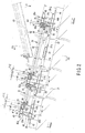
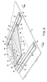
FIG. 1 is a perspective view showing a solar-power generating apparatus according to a first embodiment of the invention, and also depicting the roof of a building; -
FIG. 2 is a cross-sectional view of the solar-power generating apparatus ofFIG. 1 , installed on the roof; -
FIG. 3 is a cross-sectional view taken along line F3-F3 shown inFIG. 2 ; -
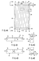
FIG. 4A is a plan view showing one of the photovoltaic modules provided in the solar-power generating apparatus ofFIG. 1 ; -
FIG. 4B is a top view of the photovoltaic module looked in the direction of arrow F4B shown inFIG. 4A ; -
FIG. 4C is a side view depicting the upper part of the photovoltaic module, looked in the direction of arrows F4C shown inFIG. 4A ; -
FIG. 4D is a bottom view of the photovoltaic module observed in the direction of arrow F4D shown inFIG. 4A ; -
FIG. 4E is a side view illustrating the lower part of the photovoltaic module, looked in the direction of arrows F4E shown inFIG. 4A ; -
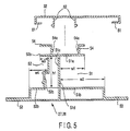
FIG. 5 is a cross-sectional view displaying the support member of the solar-power generating apparatus ofFIG. 1 , and showing the holding member that is to be attached to the support member; -
FIG. 6 is a perspective view, explaining the sequence of steps of fitting a photovoltaic module of the solar-power generating apparatus illustrated inFIG. 1 ; -
FIG. 7 is a perspective view of a solar-power generating apparatus according to a second embodiment of the invention, also depicting the roof of a building; -
FIG. 8 is a diagram illustrating the relation between the length of each photovoltaic modules used in the solar-power generating apparatus and the inter-support distance of the photovoltaic module; -
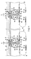
FIG. 9 is a cross-sectional view of the solar-power generating apparatus ofFIG. 7 , installed on the roof; -
FIG. 10 is a magnified, cross-sectional view showing part F10 of the apparatus illustrated inFIG. 9 ; -
FIG. 11 is a cross-sectional view taken along line F11-F11 shown inFIG. 7 ; -
FIG. 12A is a plan view showing one of the photovoltaic modules provided in the solar-power generating apparatus ofFIG. 7 ; -
FIG. 12B is a top view of the photovoltaic module looked in the direction of arrow F12B shown inFIG. 12A ; -
FIG. 12C is a side view depicting the upper part of the photovoltaic module, looked in the direction of arrows F12C shown inFIG. 12A ; -
FIG. 12D is a bottom view of the photovoltaic module observed in the direction of arrow F12D shown inFIG. 12A ; -
FIG. 12E is a side view illustrating the lower part of the photovoltaic module, looked in the direction of arrows F12E shown inFIG. 12A ; -
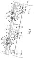
FIG.13 is a perspective view, explaining the sequence of steps fitting a solar module of the solar-power generating apparatus depicted inFIG. 7 ; -
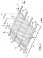
FIG. 14 is a perspective view of a solar-power generating apparatus also depicting the roof of a building; -
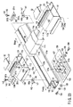
FIG. 15 is a perspective view of the support device of the solar-power generating apparatus ofFIG. 14 , illustrating some parts separated from other parts of the support device; -
FIG. 16A is a partially cross-sectional view of the support device of the solar-power generating apparatus ofFIG. 14 ; -
FIG. 16B is a cross-sectional view taken along line F16-F16 shown in FIG.FIG. 16A ; -
FIG. 17 is a perspective view of a bolt receptacle that the support device ofFIG. 15 has; -
FIG. 18 is a cross-sectional view of the crossing section of the support member used in the solar-power generating apparatus ofFIG. 14 , explaining how the bolt receptacle is embedded in this section; -
FIG. 19 is a perspective view showing of a bolt receptacle of the support device used in a solar-power generating apparatus; -
FIG. 20 is a cross-sectional view of the crossing section of the support member used in the solar-power generating apparatus ofFIG. 19 ; -
FIG. 21 is a perspective view showing of a bolt receptacle of the support device used in a solar-power generating apparatus; -
FIG. 22 is a partially cross-sectional view of the crossing section of the support member used in the solar-power generating apparatus shown inFIG. 21 ; -
FIG. 23 is a perspective view of the support device of a solar-power generating apparatus, illustrating some parts separated from other parts of the support member; -
FIG. 24A is a cross-sectional view of the crossing section of the support member used in the solar-power generating apparatus ofFIG. 23 ; -
FIG. 24B is a cross-sectional view taken along line F24-F24 shown inFIG. 24A ; -
FIG. 25 is an exploded view depicting the relation between a bolt, a support-holding member, a bolt receptacle and the like, all used in the support device of the solar-power generating apparatus; -
FIG. 26 is a perspective view of a solar-power generating apparatus according to a seventh embodiment of the invention, showing the roof of a building, too; -
FIG. 27 is a cross-sectional view taken along line F27-F27 shown inFIG. 26 ; -
FIG. 28 is a partly cross-sectional, plan view showing a part of the solar-power generating apparatus ofFIG. 26 , to which a holding member has yet to be attached; -
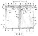
FIG. 29 is a plan view displaying the electrical connection between two adjacent photovoltaic modules in the solar-power generating apparatus illustrated inFIG. 26 ; -
FIG. 30A is a perspective view showing one of the photovoltaic modules used in the solar-power generating apparatus ofFIG. 30 , illustrating the back of the photovoltaic module; -
FIG. 30B is a cross-sectional view taken along line F30B-F30B shown inFIG. 30A ; -
FIG. 30C is a magnified, cross-sectional view showing part F30C ofFIG. 26 ; and -
FIG. 31 is a cross-sectional view showing a solar-power generating apparatus according to an eighth embodiment of the present invention. - The solar-power generating apparatus shown in
Figs. 14-25 described on pages 47-67 does not fall under the wording of the claims. - The first embodiment of the present invention will be described, with reference to
FIGS. 1 to 6 . - In
FIGS. 1 to 3 ,reference numeral 21 indicates the roof of a building, which slopes downwards from the ridge toward the eaves. Theroof 21 has a plurality of tile-supportingbars 22 on its upper surface. The tile-supportingbars 22 are used as support bases. They extend in the direction theroof 21 slopes (that is, between the ridge and eaves of the roof). They are arranged are spaced, at regular intervals, in the direction (transverse direction) that is perpendicular to the direction theroof 21 slopes upwards from the eaves to the ridge. - On the
roof 21 there is installed a solar-power generating apparatus 25 that generate electric power from the solar rays. Theapparatus 25 comprises a plurality ofsupport members 26 to 29, a plurality ofphotovoltaic modules 30, at least oneauxiliary rail 31, a plurality of holdingmembers 32, and a plurality ofstoppers 33. The holdingmembers 32 are secured to thesupport members 26 to 29. Theauxiliary rail 31 may not be used. - The
support members 26 to 29 are shaped like a rail. They are fastened to the tile-supportingbars 22 with screws or the like. Thesupport members 26 to 29 thus fastened are parallel to one another, each extending in the transverse direction of theroof 21. Any adjacent two of thesupport members 26 to 29 are set apart by a distance that accords with the length of the photovoltaic modules 30 (i.e., the distance over which each module extends in the direction the roof slopes). Each of thesupport members 26 to 29 is constituted by at least one or more elements having a prescribed length, depending upon the size of the solar-power generating apparatus 25. If each support member is composed of two or more elements, the elements are axially aligned and connected together. - The
support members support members 27 and 18 that lie between the end rails are called "intermediate support members" or "intermediate rails." Of two support members arranged adjacent in the direction the roof slopes, the one closer to the ridge is called "ridge-side support member," and the other closer to the eaves is called "eaves-side support member." - The
support member 26 is a bar of aluminum alloy, formed by extrusion. Thesupport member 26 has an up-open groove 40, a down-open groove 41, a pair offlanges 42, and a pair of member-holdingportions 43. - The
support member 26 lies on theroof 21 as is illustrated inFIG. 2 . In this state, the up-open groove 40 opens toward the ridge of the roof, and the down-open groove 41 toward the eaves of the roof. The twoflanges 42 lie below thegrooves portions 43 lie above thegrooves grooves flanges 42 and member-holdingportions 43 continuously extend in the lengthwise direction of thesupport member 26. - The up-
open groove 40 is defined between an upper groove-wall 40a and a lower groove-wall 40b. Agroove wall 26a closes thegroove 40. The down-open groove 41 is defined between an upper groove-wall 41a and a lower groove-wall 41b, which are parallel to each other. Agroove wall 26b closes thegroove 41. The down-open groove 41 is deeper than the up-open groove 40. The up-open groove 40 and the down-open groove 41, which are position back to back, have a height h1 that is smaller than the thickness h of thephotovoltaic modules 30. The upper groove-wall 41a has a width w1 that is smaller than the width w2 of the lower groove-wall 41b. Due to this relation in terms of width, the down-open groove 41 has a broader opening than in the case where the upper groove-wall 41a and lower groove-wall 41b have the same width. - The
flanges 42 project from the lower edge of thesupport member 26 in the widthwise direction thereof. Screws (not shown) pass through theseflanges 42 and are driven into the tile-supportingbars 22, thus securing thesupport member 26 on theroof 21. The member-holdingportions 43 have a standing strip and an end strip. The end strip is bent and extends from the standing strip. The standing strips of the member-holdingportions 43, which oppose each other, have a claw-holding part (not shown) each. The claw-holding parts are identical in configuration to the claw-holdingparts 54a of thesupport members portions 43 may not be used if the solar-power generating apparatus 25 does not comprise the holdingmembers 32. - The
support member 29 is a bar of aluminum alloy, formed by extrusion. It is of the same configuration as thesupport member 26. Namely, thesupport member 29 has an up-open groove 45, a down-open groove 48, a pair offlanges 46, and a pair of member-holdingportions 47. - The
support member 29 lies on theroof 21.
In this state, the up-open groove 45 opens toward the ridge of the roof, and the down-open groove 48 toward the eaves of the roof. The twoflanges 46 lie below thegrooves portions 47 lie above thegrooves open groove 48, up-open groove 45,flanges 46 and member-holdingportions 47 continuously extend in the lengthwise direction of thesupport member 29. - The up-
open groove 45 is defined between an upper groove-wall 45a and a lower groove-wall 45b. Agroove wall 29a closes thegroove 45. The down-open groove 48 is defined between an upper groove-wall 48a and a lower groove-wall 48b, which are parallel to each other. Agroove wall 29b closes thegroove 48. The down-open groove 48 is deeper than the up-open groove 45. Thegrooves photovoltaic modules 30. The upper groove-wall 45a has a width w3 that is smaller than the width w4 of the lower groove-wall 45b. Due to this relation in terms of width, the up-open groove 45 has a broader opening than in the case where the upper groove-wall 45a and lower groove-wall 45b have the same width. - The
flanges 46 project from the lower edge of thesupport member 29 in the widthwise direction thereof. Screws (not shown) pass through theseflanges 46 and are driven into the tile-supportingbars 22, thus securing thesupport member 29 on theroof 21. The member-holdingportions 47 have a standing strip and an end strip. The end strip is bent and extends from the standing strip. The standing strips of the member-holdingportions 47, which oppose each other, have a claw-holding part (not shown) each. The claw-holding parts are identical in configuration to the claw-holdingparts 54a of thesupport members portions 47 may not be used if the solar-power generating apparatus 25 does not comprise the holdingmembers 32. - The
support members support members support members open groove 51, an up-open groove 52, a pair offlanges 53, and a pair of member-holdingportions 54. - The
support members roof 21 as shown inFIGS. 2 and5 . In this state, the down-open grooves 51 open downwards, toward the eaves of theroof 21, while the up-open grooves 52 open upwards, toward the ridge of theroof 21. Theflanges 53 lie below thegrooves portions 54 lie above thegrooves open grooves 51, up-open grooves 52,flanges 53 and member-holdingportions 54 continuously extend in the lengthwise direction of thesupport members - Each down-
open wall 51 is defined, each between an upper groove-wall 51a and a lower groove-wall 51b, which are parallel to each other. Agroove wall 51c closes eachgroove 51. The down-open groove 51 is deeper than the up-open grooves 52. The down-open groove 51 has a height h1 that is smaller than the thickness h of thephotovoltaic modules 30. The upper groove-wall 51a has a width w1 that is smaller than the width w2 of the lower groove-walls 51b. Due to this relation in terms of width, the down-open groove 51 has a broader opening than in the case where the upper groove-walls 51a and lower groove-wall 51b have the same width. - Each up-
open groove 52 is defined between an upper groove-wall 52a and a lower groove-wall 52b and positioned back to back with respect to the down-open groove 51. Agroove wall 52c closes the up-open groove 52. The up-open groove 52 has a height h1 smaller than the thickness h of thephotovoltaic modules 30. The upper groove-wall 52a has a width w3 that is smaller than the width w4 of the lower groove-wall 52b. Due to this relation in terms of width, the up-open groove 52 has an opening that is larger than in the case where the upper groove-wall 52a and lower groove-wall 52b have the same width. - The
flanges 53 project from the lower edge of each of thesupport members flanges 53 and are driven into the tile-supportingbars 22. Thus, thesupport members roof 21. The member-holdingportions 54 have a standing strip and an end strip. The end strip is bent and extends from the standing strip. The standing strips of the member-holdingportions 54, which oppose each other, have a claw-holdingpart 54a each. The claw-holdingparts 54a are, for example, projections as is illustrated inFIG. 5 . Alternatively, the claw-holdingparts 54a may be stepped parts. The member-holdingportions 54 may not be used if the solar-power generating apparatus 25 does not comprise the holdingmembers 32. - As
FIG. 4A andFIG. 6 show, each of thephotovoltaic module 30 comprises arectangular module body 61, ametal frame 60 attached to themodule body 61, and aterminal box 62 fastened to the back of themodule body 61. Theframe 60 is composed of anupper bar 63, alower bar 64, aleft side bar 65, and aright side bar 66, which are made of aluminum alloy, formed by extrusion and coupled together. - The
upper bar 63 fitted in the upper edge of themodule body 61. Thelower bar 64 is fitted in the lower edge of themodule body 61. The side bars 65 and 66 are fitted in the left and right sides of themodule body 61, respectively. Thebars 63 to 66 are coupled together, forming a frame, by means ofscrews 67 shown inFIGS. 4B to 4E . InFIGS. 2 and3 ,reference numerals 68 designate gaskets. - The
module body 61 comprises a rectangular substrate and photovoltaic cells thin-film type. The substrate is made of transparent glass. The photovoltaic cells are provided on the back of the substrate and covered with a sealing layer. - The structure of the photovoltaic cells will be described. A transparent electrode layer is formed on the substrate of transparent glass. This layer is divided into a plurality of photo-electromotive regions. A thin-film, photo-electromotive semiconductor layer is formed on the transparent electrode layer. The semiconductor layer is divided into a plurality of regions (or photo-electromotive elements). A back electrode layer is formed on the photo-electromotive elements, thus electrically connecting these elements in series. Each photovoltaic cell has a pair of bus regions. The bus regions serve as the terminals of the electrical connection, for collecting electric power. Bus bars are soldered to the bus regions, respectively, and function as electrodes.
- Two lead wires are soldered at one end to the bus bars of the photovoltaic cell that has the structure specified above. The lead wires penetrate the aforementioned sealing layer and are connected to the
terminal box 62. To theterminal box 62 there are connected two output cables (not shown), i.e., positive and negative cables. - The frame bars 63 to 66 have the same thickness h3, which is the thickness of the
photovoltaic module 30. Theupper bar 63 andlower bar 64 of the frame contact any of the lower groove-walls FIG. 3 shows, the side bars 65 and 66 havelower strips auxiliary rail 31 supports these strips. - As seen from
FIG. 2 andFIGS. 4A to 4C , aninsertion projection 71 protrudes from, and is integrally formed of, theupper bar 63. Theprojection 71 lies at a midpoint over the thickness of theupper bar 63. More precisely, theprojection 71 should better be provided at a position above said midpoint, preferably at a distance of one-third of the thickness h3 of theupper bar 63 below the upper surface of theupper bar 63. Theinsertion projection 71 catches and, hence, holds the upper groove-wall projection 71 is a thin flat plate that is far thinner than theupper bar 63. It extends in the lengthwise direction of theupper bar 63. Theprojection 71 has a width w6 that is several times as much as the width w7 of aninsertion projection 75. Theinsertion projection 75 will be described later. -
Buffering members 72 are bonded to the upper surface of theinsertion projection 71, at least the end portions thereof. Thebuffering members 72 may be preferably rubber strips. Instead of rubber strips, black foamed tapes may be used, which are coated with adhesive on one side. The foamed tapes can be made of ethylene-propylene elastomer such as EPM (Ethylene-Propylene Copolymer), EPDM (Ethylene-Propylene Polymer) or the like. AsFIGS. 4A and 4B show, a pair ofbuffering members 72 are spaced apart. This helps not only to reduce the required amount of material and lower the manufacturing cost, but also to make it easy for the user to perceive whether the buffering members are provided or not. Thebuffering members 72 may be adhered to the lower surfaces of the upper groove-walls - The
lower bar 64 is as thick as theupper bar 63. As illustrated inFIG. 2 andFIGS. 4A, 4B and 4C , theinsertion projection 75 protrudes from, and is integrally formed with, thelower bar 64. Thisprojection 75 lies at a part of thelower bar 64, which is middle in the direction of thickness of thelower bar 64. More specifically, theinsertion projection 75 may be located a little above the midpoint in the thickness direction. Preferably, theprojection 75 may lie below the upper surface of thelower bar 64, at a distance that is a third of the thickness h3 of thelower bar 64. Theinsertion projection 75 contacts either the upper groove-wall 45a or the upper groove-wall 52a. It is thereby held by thewall projection 75 is a flat, thin plate that is far thinner than thelower bar 64. It extends along the entirelower bar 64. Theinsertion projection 75 has a width w7 that is much smaller than the width w6 of theinsertion projection 71. -
Buffering members 76 are adhered to the upper surface of theinsertion projection 75, at least the end portions of theprojection 75. Thebuffering members 76 are elastic members, preferably rubber strips. Instead of the rubber strips, black foamed tapes may be used, which are coated with adhesive on one side. The foamed tapes can be made of ethylene-propylene elastomer such as EPM, EPDM or the like. AsFIGS. 4A and 4D display, a pair ofbuffering members 76 are spaced apart. This helps not only to reduce the amount of material required for themembers 76 and lower the manufacturing cost, but also to make it easy for the user to perceive whether the buffering members are provided or not. Thebuffering members 76 may be adhered to the lower surfaces of the upper groove-walls - As illustrated in
FIG. 1 , eachauxiliary rail 31 lies between two adjacent support members, one close to the ridge of theroof 21 and the other close to the eaves of theroof 21 and extends parallel to these support members. Theauxiliary rails 31 are hollow bars made of aluminum alloy, formed by extrusion. AsFIG. 2 shows, eachauxiliary rail 31 has aflange 31a that projects in the widthwise direction. Theauxiliary rails 31 are fastened to theroof 21 by means of screws (not shown) that pass through therails 31 and are driven into the tile-supportingbars 22. - Symbol A in
FIG. 2 indicates the distance by which thephotovoltaic module 30 is spaced apart from a tile-supportingbar 22, or the distance between the upper surface of theauxiliary rail 31 and the upper surface of the lower groove-wall power generating apparatus 25. Thesupport members 26 to 29 and theauxiliary rails 31 can therefore be thin, which lowers the manufacturing cost. - The holding
members 32 are bars of aluminum alloy, formed by extrusion. Themembers 32 have a length that is an integral multiple of the width of thephotovoltaic modules 30. The holdingmembers 32 shown in the drawing are as long as thephotovoltaic modules 30 are broad. As best shown inFIG. 5 , each holdingmember 32 has two frame-holdingportions 81 and twoengagement claws 82. The frame-holdingportions 81 are provided at the lateral edges of themember 32. Theclaws 82 lie between the frame-holdingportions 81. The holdingmember 32 is pushed from above onto the member-holdingportion 54 of onesupport member engagement claws 82 fitted in the claw-holdingparts 54a of the member-holdingportion 54. - The
stoppers 33 are bars of aluminum allow, formed by extrusion. As shown inFIG. 1 , thestoppers 33 extend at right angles to the direction theroof 21 slopes upwards from the eaves to the ridge. Thestoppers 33 are secured, holding thephotovoltaic modules 30 that are arranged, side by side, in the transverse direction of theroof 21. To be more specific, thestoppers 33 are coupled to theauxiliary rails 30, respectively, byscrews 85 as best shown inFIG. 3 . Thus secured, thestoppers 33 prevent thephotovoltaic modules 30 from moving, which are arranged in the transverse direction of theroof 21. - The sequence of installing the solar-
power generating apparatus 25 on theroof 21 will be explained below. - First, the
support members support members roof 21 slopes. Thesupport members 26 to 29 thus laid are fastened to theroof 21. Theauxiliary rails 31 are laid, each between two support members that are adjacent in the direction theroof 21 slopes and each parallel to thesupport members 26 to 29. Therails 31 thus laid are fastened to theroof 21. Thesupport members 26 to 29 and theauxiliary rails 31 are secured by screws to the tile-supportingbars 22 that are laid on theroof 21. It does not matter whether thesupport members 26 to 29 are fastened before theauxiliary rails 31, or vice versa. - Then, the
photovoltaic modules 30 are fitted, each in a ridge-side support member and the adjacent eaves-side support member. How each photovoltaic module is laid and secured to the ridge-side support member 28 and the eaves-side support member 29. - First, the
photovoltaic module 30 is inclined in a direction opposite to the direction theroof 21 slopes, as depicted by the two-dot dashed lines inFIG. 2 or by the solid lines inFIG. 6 . Theinsertion projection 71 of theupper bar 63 of themodule 30 is inserted into the down-open groove 51 of the ridge-side support member 28. InFIGS. 2 and6 , arrow C indicates the direction themodule 30 is inserted. Next, thephotovoltaic module 30 is turned around the ridge-side support member 28 or theupper bar 63, moving thelower bar 64 toward the eaves-side support member 29. Arrow D inFIGS. 2 and6 indicates the direction in which themodule 30 is rotated. As themodule 30 is so rotated, thelower bar 64 approaches and opposes the up-open groove 45 of the eaves-side support member 29. Thereafter, let thephotovoltaic module 30 move to the eaves-side support member 29 under its own weight, in the direction of arrow E shown inFIGS. 2 and6 . The hands may be used to move thephotovoltaic module 30 more readily in the direction of arrow E. As themodule 30 is so moved, theinsertion projection 75 provided on thelower bar 64 is inserted into the upper-open groove 45. In this case, theinsertion projection 71 remains inserted in the down-open groove 51, due to the relation between the width of theprojection 71 and the depth of the down-open groove 51. Thus, thephotovoltaic module 30 is partly fitted in theadjacent support members - All
photovoltaic modules 30 are sequentially laid on theroof 21 by the method described above. Once eachphotovoltaic modules 30 is so laid, the middle parts of its side bars 65 and 66 are mounted on oneauxiliary rail 31. Thus, theauxiliary rail 31 holds the back of thephotovoltaic module 30. The side bars 65 and 66 of eachphotovoltaic module 30 contact theside bar 66 of one adjacent photovoltaic module and theside bar 65 of the other adjacent photovoltaic module, respectively (seeFIG. 3 ). - After the
photovoltaic modules 30 are arranged as described above, thestoppers 33 are laid at the ends of each group ofphotovoltaic modules 30. Thestoppers 33 are fastened by screws to the auxiliary rails 31. Thestoppers 33 therefore secure thephotovoltaic modules 30 of each group, preventing them from moving in the transverse direction of theroof 21. - Finally, the holding
members 32 are laid on thesupport members 26 to 29, concealing them. The holdingmembers 32 are then aligned with, and pressed onto, thesupport members 26 to 29. Theengagement claws 82 of the holdingmembers 32 are fitted into the claw-holdingparts 54a of thesupport members 26 to 29. Thus, the holdingmembers 32 are secured to thesupport members 26 to 28 and covers thesupport members 26 to 29. Themembers 32 thus secured hold, from above, theupper bar 63 andlower bar 64 of eachphotovoltaic module 30. Theupper bar 63 and thelower bar 64 are clamped between the frame-holdingportion 81 and the lower groove-walls members 32 may be secured to thesupport members 26 to 29, before thestoppers 33 are fastened to the auxiliary rails. - The solar-
power generating apparatus 25 is installed on theroof 21 in the sequence of steps, described above. In the step of arranging the modules, it is unnecessary to insert the thickest part of theupper bar 63 into the down-open groove bar 63 upwards and obliquely. Theinsertion projection 71, which is a thin flat plate, is moved upwards and obliquely until it is inserted into the down-open groove insertion projection 71 would not slide in acute friction on the upper groove-wall 41a of the down-open groove 41 or the upper groove-wall 51a of the down-open groove 51. This renders it easy to insert theprojection 71 into the down-open groove - The line connecting the point where the
upper bar 63 contacts the lower groove-wall insertion projection 75 in this embodiment) is shorter, by the width w6 of theprojection 71, than such a ling that connects the that point and the outermost point when the wholeupper bar 63 is inserted into the down-open groove insertion projection 75 of thelower bar 64 hardly abuts on the upper groove-wall photovoltaic module 30 is rotated to move thelower bar 64 toward the eaves-side support member. It is therefore easy to rotate the photovoltaic module, even if the support members are arranged at short intervals in the direction theroof 21 slopes upwards from the eaves to the ridge. - The down-
open groove 41 has a broad opening, because the width w2 of the lower groove-wall 41b is smaller than the width w1 of the upper groove-wall 41a. Similarly, the up-open groove 45 has a broad opening, because the width w3 of the upper groove-wall 45a is smaller than the width w4 of the upper groove-wall 51a. Likewise, the up-openedgroove 52 has a broad opening, because the width w3 of the upper groove-wall 52a is smaller than the width w4 of the lower groove-wall 52b. - In view of this, too, the
insertion projection 75 can be prevented from being caught and held by the upper groove-walls photovoltaic module 30 is secured in the module-fitting sequence described above. Additionally, theinsertion projection 71 can be inclined at large angles when it is moved into the down-open groove insertion projection 71 is thin, but also because thegrooves projection 71 into the down-open groove projection 71 inclines when inserted, is defined by theroof 21 and thephotovoltaic module 30 that is inclined in the opposite direction. - The
terminal box 62 is provided on the back of thephotovoltaic module 30 and located close to theupper bar 63. Theupper bar 63 must assume such a position that it turns upward, in order to arrange thephotovoltaic module 30. Since theupper bar 63 has theinsertion projection 71 that has width w6 larger than that of theinsertion projection 75, the position in which themodule 30 is secured can be determined from the position of theinsertion projection 71. This reduces the possibility that thephotovoltaic module 30 is secured in a wrong orientation. - Thus, the
photovoltaic modules 30 can be easily laid if they are secured in the sequence of steps, which has been described above. - The
upper bar 63 of eachphotovoltaic module 30 thus installed lies on the lower groove-wall 41b of the down-open groove 41 or on the lower groove-wall 51b of the down-open groove 51. Theinsertion projection 71 protruding from theupper bar 63 is caught and held by the upper groove-wall 41a of the down-open groove 41 or the upper groove-wall 51a of the down-open groove 51, bothgrooves upper bar 63 is therefore prevented from moving in the direction of its thickness. - In this state, the
buffering members 72 clamped between the upper groove-wall insertion projection 71 prevents thephotovoltaic module 30 from being loosely supported. More precisely, the projecting edge of the upper groove-wall member 72, the ridge-side part of which is held between the upper groove-wall insertion projection 71 lying below thewall photovoltaic module 30 can be firmly held. In addition, the area in which the bufferingmember 72 and the upper groove-wall buffering members 72 would not hinder the moving of thephotovoltaic modules 30 in the transverse direction of theroof 21. - Similarly, the
lower bar 64 is laid on the lower groove-wall 45b of the up-open groove 45 or on the lower groove-wall 52b of the down-open groove 52. Theinsertion projection 75 of thelower bar 64 is caught and held by either the upper groove-wall 45a of the up-open groove 45 or the upper groove-wall 52a of the up-open groove 52, bothgrooves lower bar 64 from moving in the direction of its thickness. In this case, too, the butteringmembers 76 clamped between the upper groove-wall insertion projection 75 can prevent thephotovoltaic module 30 from moving toward the ridge or eaves of the roof. - Therefore, the
photovoltaic modules 30 would not slip out from the space between any two adjacent support members that are spaced apart in the direction theroof 21 slopes upwards from the eaves to the ridge. - The
upper bar 63 andlower bar 64 of eachphotovoltaic module 30 are held from above by the frame-holdingportions 81 of the holdingmembers 32 that are provided on the twoadjacent support members 26 to 29. The holdingmembers 32 prevent thephotovoltaic module 30 from slipping out of the space between the adjacent support members that are spaced apart in the direction the roof slopes. The holdingmembers 32 therefore help to achieve firm and steady installation of thephotovoltaic module 30. - Each holding
member 32 lies above one support member (26, 27, 28 or 29), concealing the entire upper surface of the support member. The shape of the upper surface of the support member does not jeopardize the outer appearance of the solar-power generating apparatus 25. The solar-power generating apparatus 25 can attain a good outer appearance. - Two
stoppers 33 are provided at the ends of each group ofphotovoltaic modules 30 that are laid on theroof 21 and arranged in the lengthwise direction of thesupport members 26 to 29. Thestoppers 33 prevent thephotovoltaic modules 30 from moving in said lengthwise direction. Thus, no measures need be taken to prevent allphotovoltaic modules 30 of each group from moving. This greatly decreases the number of screws and other fixing members required for installing the solar-power generating apparatus 25. - As mentioned above, it is easy to secure each
photovoltaic module 30 to and arrange between a ridge-side support member and the adjacent eaves-side support member in the process of installing the solar-power generating apparatus 25. Additionally, the number of screws required for the installation is very small. The efficiency of installing the solar-power generating apparatus 25 on theroof 21 therefore increases. - In the solar-
power generating apparatus 25, the thickest part of theupper bar 63 of eachphotovoltaic module 30 need not be inserted into the down-open groove lower bar 64 need not be inserted into the up-open groove open groove open groove photovoltaic module 30. It follows that thesupport members 26 to 29, each having these grooves, can have a smaller height than otherwise. - It is therefore possible to lower the material cost of the
support members 26 to 29 and, ultimately the manufacturing cost of the solar-power generating apparatus 25. Further, the number of the fixing members, such as screws, required for installing the solar-power generating apparatus 25 can be greatly reduced. Thus, the number of steps securing the apparatus can be reduced, too. This also serves to decrease the cost of installing the solar-power generating apparatus 25. - The solar-
power generating apparatus 25 comprisesauxiliary rails 31 that are secured to theroof 21. Therails 31 support thephotovoltaic modules 30, at the parts that are middle in the direction theroof 21 slopes upwards from the eaves to the ridge. Thus supported, thephotovoltaic modules 30 are sufficiently resistant to the wind pressure applied to them downwards when a strong wind blows. The side bars 65 and 66 of eachphotovoltaic module 30 need not withstand the wind pressure. Not only the side bars 65 and 66, but also theupper bar 63 and thelower bar 64 can be thinner than otherwise. As a result, thephotovoltaic modules 30 can be thinner as a whole. This helps to reduce the manufacturing cost of thephotovoltaic modules 30 and, ultimately, the manufacturing cost of the solar-power generating apparatus 25. - Since the
photovoltaic modules 30 can be made thin, the height of the solar-power generating apparatus 25 can be decreased. The step defined by theroof 21 and theapparatus 25 installed on theroof 21 is therefore low, improving the outer appearance of the solar-power generating apparatus 25. Particularly, the solar-power generating apparatus 25 has a small height G of (FIG. 2 ) that is about 40 mm, measured from the upper surface of each tile-supportingbar 22. If tiles are laid around the solar-power generating apparatus 25, the upper surface of each tile lies almost flush with the upper surface of the solar-power generating apparatus 25. This serves to greatly enhance the outer appearance of theroof 21. - The second embodiment of the present invention will be described, with reference to
FIGS. 7 to 13 . The second embodiment is basically the same as the first embodiment. Therefore, the components identical to similar to those of the first embodiment are designated at the same reference numerals and will not be described. Only the components different from those of the first embodiment will be explained. - The second embodiment differs from the first embodiment in that the lower groove-wall of each support member has a width that is set in accordance with the photovoltaic modules in order to make it easy to secure the photovoltaic modules; means is provided to prevent the photovoltaic modules from moving after the modules are secured; the earth cables are simplified; auxiliary rails are not used as in the first embodiment; and spacers are attached to the photovoltaic modules.
- The second embodiment is a solar-
power generating apparatus 25 installed on a sloping slatedroof 21. The solar-power generating apparatus 25 comprises support bases 23,support members 26 to 29, and a plurality ofphotovoltaic modules 30. The support bases 23 are laid on theroof 21, each extending from the ridge to the eaves. Thesupport members 26 to 29 are laid on the support bases 23, each crossing the support bases 23 at right angles. Thephotovoltaic modules 30 are arranged on the adjacent support members that are spaced apart in the direction theroof 21 slopes. - The lower groove-
walls walls 42a and 45a. AsFIGS. 8 and9 show, the distance L between the bottom surface 41d of thegroove wall 26b of the down-open groove 41, or thebottom surface 51d of the bottom 51c of the down-open groove 51, and the ridge-side ends of the lower groove-walls insertion projection 71 of thephotovoltaic module 30 and the root of theinsertion projection 75 of thephotovoltaic module 30. The distance N between the eaves-side ends of the lower groove-walls walls photovoltaic modules 30 are supported at ends. The lower groove-walls - As is best shown in
FIG. 10 , the member-holdingportions support members 26 to 29 are upright strips that do not cover the upper groove-walls support members 26 to 29. - A plated layer (not shown) is formed on the surfaces of the frame bars 63 to 66 of each
photovoltaic module 30, and a transparent protective layer (not shown) is formed on the plated layer.Reference numerals FIG. 11 denote the tapping holes made in the side bars 65 and 66, into which screws 67 are driven to assemble theframe 60. - As
FIG. 11 ,12A and13 show, twospacers 69 are bonded to the ends of theouter side 65b of theside bar 65, and twospacers 69 are bonded to the ends of theouter side 66b of theside bar 66. Thespacers 69 are made of buffering material that can elastically deform. They are, for example, rubber plates 0.5 mm to 3 mm thick. Alternatively, thespacers 69 may be foamed tapes made of black EPDM, each having one side coated with adhesive. It suffices to interposespacers 69 between adjacentphotovoltaic modules 30. Thespacers 69 may be provided on the outer side of only theside bar - The side bars 65 and 66 of each
photovoltaic module 30 have been made by extrusion using the same mold. They have the same cross-sectional shape (seeFIG. 11 ). Insulatedelectric wires wires photovoltaic modules 30 to the ground. Note that themodules 30 are arranged in the transverse direction of theroof 21. Theelectric wires FIG. 12A , they are secured at one end to the side bars 65 and 66 atpoints - To be more specific, a
metal terminal 94a is secured to one end of theelectric wire 94 by means of pressing. Ascrew 96 made of metal fastens the terminal 94a to theside bar 65, preferably at aposition 94b that lies at a distance from the upper end of theside bar 65, said distance being about a third or quarter of the length of theside bar 65. Thescrew 96 is driven into thelower wall 65c of theside bar 65, passing through theterminal 94a (seeFIG. 11 ). Since the terminal 94a is thus secured to thewire 94, theelectric wire 94 is electrically connected to theside bar 65 by thescrew 96. Ametal terminal 95a is secured to one end of theelectric wire 95 by means of pressing. Ascrew 97 made of metal fastens the terminal 95a to theside bar 66, preferably at aposition 95b that lies at a distance from the lower end of theside bar 66, said distance being about a third or quarter of the length of theside bar 66. Thescrew 97 is driven into thelower wall 66c of theside bar 66, passing through theterminal 95a (seeFIG. 11 ). It is with respect to point Q shown inFIG. 12 that thepositions - As
FIGS. 11 ,12A and13 show, theelectric wire 94 has amale connection terminal 98 at its distal end. The terminal 98 is made of metal and secured to thewire 94 by pressing. An insulatingtube 99 covers the pressed part of the terminal 98. Theelectric wire 95 has afemale connection terminal 100 at its distal end. This terminal 100 is made of metal and secured to thewire 95 by pressing. An insulatingtube 101, which is longer than the terminal 100, covers thefemale connection terminal 100. Themale connection terminal 98 can be inserted into thefemale connection terminal 100 and thereby be connected to the terminal 100. When the terminal 98 is thus connected to the terminal 100, the insulatingtube 99 covers the distal part of the insulatingtube 101. At the time theterminals photovoltaic module 30 are electrically connected to one another. The second embodiment is identical in structure to the first embodiment, except for the points explained above. - The second embodiment is advantageous over the first embodiment in the following respects. In the second embodiment, the distance L between the bottom surface 41d of the down-
open groove 41 of the ridge-side support member, or thebottom surface 51d of the down-open groove 51 of the down-side support member, and the ridge-side ends of the lower groove-walls insertion projection 71 of thephotovoltaic module 30 and the root of theinsertion projection 75 of thephotovoltaic module 30. Hence, thelower bar 64 is hardly be held at the ridge-side ends of the lower groove-walls photovoltaic module 30 is rotated on the ridge-side support member to move toward the eaves-side support member in the process of installing themodule 30 by securing the same to the support members. Thus, thelower bar 64 can reliably mounted on bothlower grooves walls photovoltaic module 30. - In the second embodiment, the lower groove-
walls upper bars 63 of thephotovoltaic modules 30 can easily abut on the lower groove-walls upper bars 63 are inserted into the down-open grooves photovoltaic modules 30 in the course of fastening the modules. Namely, the lower groove-walls upper bars 63 into the down-open grooves photovoltaic modules 30. - In the second embodiment, the lower groove-
walls walls photovoltaic module 30 is supported at ends is, therefore, short. This gives thephotovoltaic module 30 an increased resistance to the wind pressure applied to the bottom of themodule 30. The frame bars of eachphotovoltaic module 30 need not withstand the wind pressure by themselves. The frame bars 63 to 66 can be made thin. Ultimately, the solar-power generating apparatus 25 can be thin and be manufactured at low cost. Since the aforementioned pressure resistance is increased in the second embodiment, it is not necessary to used auxiliary rails as in the first embodiment. This further lowers the manufacturing cost. - In the solar-
power generating apparatus 25 that is the second embodiment, anyphotovoltaic modules 30 adjacent in the transverse direction of theroof 21 can be electrically connected, as will be described below, when they are secured to theroof 21. Thus, thephotovoltaic modules 30 can be connected to the ground. - After any
photovoltaic module 30 is secured to the roof, the nextphotovoltaic module 30 is secured. Namely, this module is moved to themodule 30 already secured, using the ridge- and eaves-side support members as guides, until it contacts themodule 30 already secured to the roof. InFIG. 13 , arrow F indicates the direction in which thephotovoltaic module 30 is moved. When themodule 30 contacts the already secured one, theconnection terminal 98 of theelectric wire 94 attached to itsside bar 66 is connected to theconnection terminal 100 of theelectric wire 95 that is attached to theside bar 66 of the otherphotovoltaic module 30. Thus, the photovoltaic modules laid adjacent have their metal frames electrically connected to each other. Themale connection terminal 98 can be inserted into thefemale connection terminal 100, by a single manual operation. This enhances the efficiency of electrically connecting the metal frames of thephotovoltaic modules 30. - To represent the electrical connection between any adjacent
photovoltaic modules 30, thephotovoltaic module 30 being secured is shown inFIG. 13 as if already electrically connected to thephotovoltaic module 30 that has been secured. In practice, however, themodules 30 are secured in the procedure described above. Theelectric wires wires photovoltaic module 30 is secured beside thephotovoltaic module 30 already secured to the roof. - In the second embodiment, the
left side bar 65 and theright side bar 66, both made by extrusion using the same mold, are arranged symmetrically with respect to a point. Further, theelectric wires screws - Furthermore, the male and
female connection terminals electric wires bar 65 and the lower part of thebar 66, respectively. This shortens the distance for which theelectric wires wires - As indicated above, each
photovoltaic module 30 is moved in the direction of arrow to thephotovoltaic module 30 already secured to the roof. As thephotovoltaic module 30 is so moved, itsside bar 65 may abut on theside bar 66 of thephotovoltaic module 30 already secured. - The shock generated by the abutment can be buffered as the
spacers 69 that are bonded to the side bars 65 and 65 undergo elastic deformation. The shock on themodule body 61 of thephotovoltaic module 30 already secured can, therefore, be attenuated. - Once the solar-
power generating apparatus 25 has been installed, thespacers 69 is positioned between thephotovoltaic modules 30 laid adjacent to one another in the transverse direction of theroof 21, as is illustrated inFIG. 11 . A gap G corresponding to the thickness of thespacers 69 is provided between any twoadjacent modules 30. Thanks to the gap G and the elastic deformation of thespacers 69, themodule body 61 receives no extra load that may otherwise be applied when thephotovoltaic module 30 expands as it is heated with solar heat. This prevents themodule body 61 from receiving the load resulting from the thermal expansion of themodule 30. Thespacers 69 provide the gaps G naturally as the photovoltaic modules are laid one after another. No particular work needs to be performed to space themodules 30 apart from one another. This is advantageous, saving labor in laying the photovoltaic modules. - The
photovoltaic modules 30, which are considerably heavy, may be positioned, each with itsside bar spacers 69 bonded to thebars photovoltaic modules 30 receive when they are placed on the floor or the ground. This prevents themodule body 61 from receiving the shock. - In the factory or at the construction site, each
photovoltaic module 30 may be handled, with theelectric wires module body 61. Thephotovoltaic module 30 thus handled may be placed on a mounting surface H, with theside bar FIG. 12A . In this condition, thespacers 69 bonded to the side bar, for example theside bar 66, prevents theside bar 66 from contacting the mounting surface H. This is because thespacers 69 are sufficiently thick. Space apart from the mounting surface H, thebar 66 will not have its surface damaged even if thephotovoltaic module 30 is dragged in said condition. - As mentioned above, the
spacers 69 can reduce- the load that is exerted on themodule body 61 as thephotovoltaic module 30 is being laid on the roof or when it undergoes a thermal expansion after laid on the roof. Further, thespacers 69 prevent the side bars 65 and 66 from being damaged as they slide on the mounting surface H. Note that the side bars 65 and 66 have spacers 69 on only their end parts. Thus, thespacers 69 need not be used in so great numbers as in the case where they are bonded to other parts of each side bar, too. - The third embodiment of this invention will be described, with reference to
FIGS. 14 to 18 . The third embodiment is identical in basic structure to the second embodiment. The components similar or identical to those of the second embodiment will be designated at the same reference numerals and will not be described below. Only the structural features different from the second embodiment will be described. The third embodiment differs from the second in that asupport device 111 is used to support a solar-power generating apparatus. - The
support device 111 comprises a plurality of rail-shapedlongitudinal bars 112 and a plurality of rail-shaped transverse bars 113. Eachlongitudinal bar 112 extends in the longitudinal direction (i.e., direction in which the slated-roof 21 slopes upwards from the eaves to the ridge) and secured to theroof 21. It is used as a support base. Eachtransverse bar 113 is coupled to thelongitudinal bars 112 and used as a support member. Eachlongitudinal bar 112 and eachtransverse bar 113 cross each other and coupled to each other at intersection. Thelongitudinal bars 112 and thetransverse bars 113 are bars that are made of aluminum alloy and formed by extrusion. - Each
transverse bar 113 is laid, extending in the transverse direction of the roof 21 (i.e., direction perpendicular to the direction in which theroof 21 slopes upwards from the eaves to the ridge). Eachtransverse bar 113 comprises a plurality of support-bar elements 113a (seeFIG. 15 ) andcouplings 114. Theelements 113a are arranged in a line and connected together by thecouplers 114. Thetransverse bars 113 are laid parallel to one another. Thebars 113 are spaced apart in the direction theroof 21 slopes, by a distance that is equal to the length of thephotovoltaic modules 30. - The two
transverse bars 113 that lie close to the ridge and eaves of the roof, respectively, are called "end rails." The othertransverse bars 113 that lie between the end rails are called "intermediate rails." Of any two transverse bars that are arranged adjacent in the direction the roof slopes, the one closer to the ridge is called "ridge-side transverse bar," and the other closer to the eaves is called "eaves-side transverse bar." - As shown in
FIGS. 15 and16 , eachlongitudinal bar 112 has twogrooves 121 and onegroove 122. Thegrooves 121 open in the left and right sides, respectively. Thegroove 122 opens in the flatupper wall 112e. Thegrooves longitudinal bar 112. Thegrooves opening - The
grooves opening groove 122 defines arecess 122c that is narrowed bysteps 122b. Therecess 122c opposes theopening 122a. InFIG. 16B , thereference numeral 122d denotes the lateral edges of theopening 122a (also called "opening edges"). The distance J between either edge and thestep 122b is larger than the thickness K of polygonal nuts that will be described later. Thegrooves 121 are similar to thegroove 122 in structure. - Each
longitudinal bar 112 is coupled to a plurality of metal supports 123 bybolts 124 and polygonal nuts, or square nuts 125. As shown inFIG. 15 , eachmetal support 123 comprises abase plate 126 and a longitudinal-bar holding plate 127. Thebase plate 126 is fastened to theroof 21 by screws. The longitudinal-bar holding plate 127 is riveted to the upper surface of thebase plate 126. The holdingplate 127 has two side walls that oppose each other. Each side wall has abolt hole 127a that is elongated in vertical direction. - The
longitudinal bar 112 is fastened to themetal support 123, with its lower part held between the side walls of the longitudinal-bar holding plate 127 by tightening thesquare nuts 125 on thebolt 124. That is, thesquare nuts 125 are inserted into in thegrooves 121 through the openings thereof. They are set in thegrooves 121, each unable to rotate. Thebolt 124 is inserted in thesquare nuts 125, passing through thebolt holes 127a and the openings of thegrooves 121. When thebolt 124 is tightened, thelongitudinal bar 112 is secured to themetal support 123. Thus secured, thelongitudinal bar 112 inclines down toward the eaves of theroof 21. InFIG. 15 , thereference numeral 128 designates spring washers and thereference numeral 129 denotes washers. Thespring washers 128 are mounted on thebolt 124. Thewashers 129 disperse the tightening load. - The
transverse bars 113 are identical in structure. AsFIG. 16A illustrates, eachtransverse bar 113 has an up-open groove 131, a down-open groove 132, a pair offlanges portions 135. Theflanges grooves portions 135 lie above thegrooves open groove 131 is equivalent to the up-open grooves open grooves 132 are equivalent to the down-open grooves flanges flanges portions 135 are equivalent to the member-holdingportions - Once the
transverse bar 113 is laid on theroof 21, the down-open groove 132 opens downwards, sloping down toward the eaves of theroof 21. The up-open groove 132 opens upwards, sloping up toward the ridge of theroof 21. Bothgrooves flanges portions 135 continuously extend in the lengthwise direction of thetransverse bar 113. - The
flanges transverse bar 113, project from the lower edge of thetransverse bar 113. The eaves-side flange 134 has abase part 134a and an up-open edge part 34b. Thebase part 134a contacts the upper surface of thelongitudinal bar 112. The edge part 34b is bent and extends from the distal end of thebase part 134a. The eaves-side base part 134a has a groove that opens upwards. This groove holds an output cable (not shown), which is led from thephotovoltaic module 30. - The
flanges connection holes 132 each, which are made in that part of each flange that contacts the upper surface of thelongitudinal bar 112. In other words, both edges of thelongitudinal bar 112 have connection holes 136. Usually the connection holes 136 are made by those who install the solar-power generating apparatus. Nonetheless, they may be made before the apparatus is installed on theroof 21. If this is the case, the connection holes 136 may be elongated ones that extend in the lengthwise direction of thetransverse bar 113. - The
transverse rail 113 that functions as a ridge-side end rail is identical in structure to thetransverse bar 113 that functions as an intermediate rail. Though not shown, thetransverse bar 113 functioning as a ridge-side end rail has a down-open groove, a pair of flanges, and a pair of member-holding portions. Once thebar 113 is secured on theroof 21, the down-open groove downwards and slantwise, the flanges lie below the down-open groove, and the member-holding portions lie above the down-open groove. The down-open groove of thetransverse bar 113 has the same structure as thetransverse bar 113 that serves as an intermediate rail, and will be designated, when necessary, atreference numeral 132. Similarly, thetransverse bar 113 functioning as an end rail has the same structure as thetransverse bar 113 functioning as an intermediate rail. Thus, thetransverse bar 113 has an up-open groove, a pair of flanges and a pair of member-holding portion. Once thebar 113 is secured on theroof 21, the groove (not shown) opens upwards and slantwise, the flanges (not shown) lie below the groove, and the member-holding portions (not shown) lie above the groove. The up-open groove has the same structure as the up-open groove 131 of thetransverse bar 113 that works as an intermediate rail, and will be designated, when necessary, atreference numeral 131. - The flanges of the
transverse rails 113 that are the ridge-side end rail and the eaves-side end rail, respectively, are identical in structure to theflanges transverse bars 113 that function as intermediate rails. Thus, the flanges will be designated, when necessary, at thereference numerals transverse rails 113 that are the ridge-side end rail and the eaves-side end rail, respectively, are identical in structure to the member-holdingportions 135 of the othertransverse bars 113 that function as intermediate rails. Therefore, the member-holding portions will be denoted, when necessary, at thereference numeral 135. The member-holdingportions 135 extend upwards, each having claw-holding parts. - The
elements 113a of eachtransverse bar 113 have ahollow part 137 each. Thehollow part 137 extends in the lengthwise direction of theelement 113a. Any two transverse-bar elements 113a arranged adjacent in the lengthwise direction are connected together by thecouplers 114 that are arranged along thehollow parts 137. Thecouplers 114 are bars made of aluminum allow and formed by extrusion. - As
FIG. 15 shows, eachcoupler 114 has twoside walls 114a, atop wall 114b, and twolower walls 114c. Thetop wall 114b connects theside walls 114a at their upper edges. Thelower walls 114c extend from the lower edges of theside walls 114a, respectively, at right angles thereto, and approach each other. The height of thecoupler 114, or the distance between the outer surface of thetop wall 114b and the outer surface of eitherlower wall 114c, is almost the same as the height of thehollow part 137. The width of thecoupler 114, or the distance between the outer surfaces of theside walls 114a, is almost equal to the distance Z between the tapping holes 137a that are cut, as shown inFIG. 16A , in the four corners of thehollow part 137. - One end of a
coupler 114 is fitted in thehollow part 137 of one of two adjacent transverse-bar element 113a. The end of thecoupler 114 is fitted in thehollow part 137 of the other transverse-bar element 113a. Having its ends so fitted, thecoupler 114 connects the adjacent transverse-bar elements 113a and inhibits theelements 113a from moving toward the ridge or eaves of the roof. - Any
longitudinal bar 112 intersects with alltransverse bars 113 at right angles are coupled to thetransverse bars 113 at the intersection. Thebars groove 122 of thebar 112, a pair of bolt-holdingbodies bolt 143, aspring washer 144, and awasher 145. Thewasher 144 prevents thebolt 143 from loosening. Thewasher 145 disperses the tightening load on thebolt 143. - The bolt-holding
bodies groove 122 and can move in the lengthwise direction of thegroove 122. AsFIG. 17 shows, the bold-holdingbodies polygonal nut 146 and aprojection 147 each. - The
polygonal nut 146 is square. It has onescrew hole 146a. The four sides of thepolygonal nut 146 are a little broader than the bottom of thegroove 122 that has a width I as illustrated inFIG. 16A . This enables the bolt- holdingbodies groove 122. Thepolygonal nut 146 has a thickness K, which is smaller than the distance J between thestep 122b and either openingedge 122d of thegroove 122 shown inFIG. 16A . - The
projection 147 is a ribbon-shaped metal strip that has a width narrower than that of the opening 112a. It can deform and preferably has flexibility. Theprojection 147 is secured at one end to one side of thepolygonal nut 146 by means of adhesion, welding or the like. The other end of theprojection 147 is bent, forming an upright end-portion 147a. The upright end-portion 147a has such a length that it slightly protrudes from theopening 122a while the bold-holdingbody projection 147 is pushed into thegroove 112. The upright end-portion 147a can catch theflange - The bolt-holding
bodies groove 122 of thelongitudinal bar 112 laid on theroof 21, through either the ridge-side open end or eaves-side open end of thebar 112. The eaves-side bolt-holdingbody 141 is inserted into thegroove 122, with itsprojection 147 toward to the eaves of the roof. - The bolt-holding
bodies groove 122 to positions where they will be coupled to thetransverse bars 113. While thebodies screw holes 146a are aligned, respectively, with the connection holes 136 of the ridge-side flange 133 and eaves-side flange 134 of thetransverse bar 113. In this condition, thebolt 143, having thespring washer 144 and thewasher 145 mounted on it, is driven into thescrew hole 146a from above, passing through theconnection hole 136 and theopening 122a of thegroove 122 that lie beneath theconnection hole 136. In this case, thepolygonal nut 146 abuts on the inner surface of thegroove 122. Thenut 146 therefore prevents the bolt-holdingbody - As the
bolts 143 are tightened, thepolygonal nuts 146 of the bolt-holdingbodies transverse bar 113, clamping the lateral edges of theopening 122a. As a result, thetransverse bar 113 is coupled to thelongitudinal bar 112. Thelongitudinal bar 112 and thetransverse bar 113 are coupled by performing this assembling procedure, as is illustrated inFIGS. 16A and 16B . - In the assembling procedure described above, the bolt-holding
bodies groove 122, with the upright end-portions 147a of theirprojections 147 protruding from theopening 122a of thegroove 122. Therefore, the upright end-portion 147a abuts on theflange transverse bar 113 when either bolt-holding body (141 or 142) reaches the intersection of thelongitudinal bar 112 and thetransverse bar 113. At this time, thescrew hole 146a of eachpolygonal nut 146 is roughly aligned with theconnection hole 136 of theflange - Thereafter, the upright end-
portion 147a may be pinched with fingers, thereby minutely adjusting the position of each bold-holdingbody screw hole 146a is thereby aligned with theconnection hole 136. In this condition, thebolt 143 is inserted from above, and can then be tightened. Thus, thebars - When the bolt-holding
bodies groove 122 as described above, thetransverse bar 113 loosely or tightly held by bolts may hinder the moving of thebodies portions 147a, which lie on thetransverse bar 113 loosely held, may be pushed into thegroove 122 to a level below the upper surface of thelongitudinal bar 112. Then, it is easy to release theprojection 147 of the bold-holdingbody transverse bar 113. At this time, theprojection 147 is deformed or preferably elastically deformed, or thepolygonal nut 146 is inclined since the bolt-holdingbody groove 122. - The bolt-holding
bodies groove 122 with a rod-shaped tool, such as a screw driver, inserted into thegroove 122 through theopening 122a. As a result, a bold-holdingbody 141, for example, can be passed under thetransverse bar 113 as is displayed inFIG. 18 . Bolt-holdingbodies bars transverse bar 113. - In the case where each
transverse bar 113 is composed of transverse-bar elements 113a that are connected bycouplers 114, thesupport device 111 is assembled when the transverse-bar elements 113a are connected. Consequently, anycoupler 114 holding twoadjacent elements 113a at their one end inhibits theelements 113a from moving when thesupport device 111 are lifted not to prevent the bolt-holdingbodies bar element 113a. Nevertheless, the above-mentioned inconvenience resulting from the use of thecouplers 114 is eliminated because the bolt-holdingbodies transverse bars 113, without necessity of lifting thesebars 113. Thesupport device 111 can therefore be assembled with ease. - As specified above, the
support device 111 is assembled by first drivingbolts 143, from above, at the intersections of thelongitudinal bars 112 andtransverse bars 113 and then tightening thebolds 143. In addition, it does not take time to lift thetransverse bars 113 from thelongitudinal bars 112 in order to move the bolt-holdingbodies support device 111 can be assembled with high efficiency. This enhances the efficiency of installing the solar-power generating apparatus 25 on theroof 21. - The
photovoltaic modules 30 are laid and secured in the procedure described above, each between a ridge-side transverse bar of thesupport device 111 and the adjacent eaves-side transverse bar thereof. The procedure of securing the modules is just the same as in the second embodiment. - The fourth embodiment of the invention will be described, with reference to
FIG. 19 and FIG. 20 . The fourth embodiment is basically the same as the third embodiment. The components identical or similar to those of the third embodiment will be designated at the same reference numerals and will not be described. The bolt-holdingbodies 140 that differ from their equivalents of the third embodiment will be described below. - Each bolt-holding
body 140 is made of aluminum alloy. As seen fromFIG. 19 , it is a bar that has the same width as thetransverse bars 113 and a length equal to or larger than that of thebars 113. The bolt-holdingbody 140 has twoscrew holes 140a, each in one end portion. Thescrew holes 140a are through-holes, extending in the direction of thickness of the bolt-holdingbody 140. They will be aligned with theconnection holes 136a cut in theflanges transverse bar 113. - The bolt-holding
body 140 is a little narrower than the bottom wall of thegroove 122. Its thickness is slightly smaller than the distance J between the opening edges 122d andstep 122c of thegroove 122. The bolt-holdingbody 140 lies in thegroove 122 of thelongitudinal bar 112 and can move in thegroove 122. - The bolt-holding
body 140 is used, arranged beneath thetransverse bar 113. It is positioned beneath thebar 113, by inserting a tool, such as a screw driver, into the opening of thegroove 122 at the eaves-side of thetransverse bar 113 to be secured and by using the tool as a stopper. The bolt-holdingbody 140 may have a strip (not shown), which projects from one end, as in the third embodiment. - As
FIG. 20 shows, theconnection holes 136a made in thetransverse bar 113 may preferably elongated holes that extend in he widthwise direction of thebar 113. In this case, it does not matter if thescrew holes 140a somewhat deviate from the design positions. This achieves the advantage that thelongitudinal bar 112 and thetransverse bar 113 can be fastened together at their intersection when thebolts 143 driven into the intersection from above are tightened. The fourth embodiment is identical to the third, in all other structural aspects including the aspects that are not shown inFIG. 19 or FIG. 20 . - In the fourth embodiment, too, the
longitudinal bar 112 and thetransverse bar 113 can be fastened from above at their intersection by bolts. Since each bolt-holdingbody 140 can pass under thetransverse bar 113. It is therefore unnecessary to lift thetransverse bar 113 in the course of assembling the support device. Moreover, bothscrew holes 140a made in the bolt-holdingbody 140 can be aligned at a time with the twoconnection holes 136a of thetransverse bar 113 in the fourth embodiment. - The fifth embodiment of this invention will be described, with reference to
FIG. 21 and FIG. 22 . The fifth embodiment is basically the same as the third embodiment. The components identical or similar to those of the third embodiment will be designated at the same reference numerals and will not be described. The bolt-holdingbodies 241 that differ from their equivalents of the third embodiment will be described below. - As
FIG. 21 illustrates, each bolt-holdingbody 241 comprises a pair ofpolygonal nuts 146, aconnection part 242, and aprojection 147. Thepolygonal nuts 146 have onescrew hole 146a each. Theconnection part 242 extends between the nuts 146 and connects them together. Theprojection 147 protrudes from one of the nuts 146. Theconnection part 242 is a flexible lender member such as a wire, a metal ribbon or the like. Theconnection part 242 curves, for example, downwards. Being flexible, it can be deformed, further bent or straightened up. Thus, the distance between the screw holes 146a of thepolygonal nuts 146 can be adjusted to the distance between the connection holes 136 made in thetransverse bar 113. The fifth embodiment is identical to the third, in all other structural aspects including the aspects that are not shown inFIG. 21 or FIG. 22 . - Hence, the
longitudinal bars 112 and thetransverse bars 113 can be coupled together also in the fifth embodiment, by inserting bolts from above into the intersections of the bars and by tightening the bolts. Furthermore, the bolt-holdingbodies 241 can be passed under thetransverse bars 113 to assemble the support device, without the necessity of lifting thelongitudinal bars 113 already laid. In the fifth embodiment, each bolt-holdingbody 241 has a pair ofscrew holes 146a. The screw holes 146a can be aligned with the twoconnection holes 136 of thetransverse bar 113, which are spaced apart in the widthwise direction of thebar 113. This further increases the efficiency of assembling the support device. - The sixth embodiment of this invention will be described, with reference to
FIG. 23 to FIG. 25 . The sixth embodiment is basically the same as the third embodiment. The components identical or similar to those of the third embodiment will be designated at the same reference numerals and will not be described. The sixth embodiment differs from the third embodiment in that thelongitudinal bars 112 and thetransverse bars 113 are coupled by support-holdingmembers 261. - As
FIG. 23 andFIG. 24A show, the ridge-side flange 133 of eachtransverse bar 113 has abase part 133a and an upright edge part 133b. Thebase part 113a contacts the upper surface of thelongitudinal bar 112. The upright edge part 133b is bent and extends from the distal end of thebase part 133a. The support-holdingmembers 261 are metal plates or the like. As seen fromFIG. 25 etc., each support-holdingmember 261 has been made by first bending a plate upwards, forming anupright part 261a and a base part 2161c, and then bending the upper portion of theupright part 261a horizontally, forming a holdingpart 261b. - The
upright part 261a has a height equal to or a little smaller than the height of theupright edge parts 133b and 134b. The holdingpart 261b holds the upper edge of theupright edge part 133b or 134b while theupright part 261a remains contacting theupright edge part 133b or 134b. Thebase part 261c that is supported on the upper surface of thelongitudinal bar 112 is bent in the direction opposite to the direction the holdingpart 261b is bent. Thebase part 261c has aconnection hole 136b. AsFIG. 25 depicts, theconnection hole 136b is an elongated hole that extends in the lengthwise direction of thetransverse bar 113. Being elongated, thehole 136b facilitates the positioning of the support-holdingmember 261. The sixth embodiment is identical to the third, in all other structural aspects including those not shown inFIG. 23 to FIG. 25 . - In the sixth embodiment, the
longitudinal bars 112 and thetransverse bar 113 are coupled together, at each intersection, in the sequence of steps described below. - First, support-holding
members 261 are laid from above, at each intersection of thelongitudinal bars 112 andtransverse bars 113. More precisely, eachmember 261 is positioned, with its holdingpart 261b laid on the ridge-side upright edge part 133b or eaves-sideupright edge part 134b and with itsbase part 261c mounted on the upper surface of thelongitudinal bar 112. - Next, the bolt-holding
bodies groove 112 of thelongitudinal bar 112. Thebodies groove 122 until the upright end-portions 147a of theirprojections 147 are held by thebase parts 261c. Thus, the screw holes 146a of thepolygonal nuts 146 are roughly aligned with the connection holes 136b of thebase parts 261c. In this condition, the bolt-holdingbodies screw holes 146a with the connection holes 136b as is desired. - Thereafter,
bolts 143 are inserted, from above, through the connection holes 136b of the support-holdingmembers 261. The bolts are then driven into the screw holes 146a of the bolt-holdingbodies - The
opening edge 122d of thegroove 122 of thelongitudinal bar 112 is thereby held between the bolt-holdingbody base part 261c of the support-holdingmember 261. Theflange transverse bar 113 is clamped between the holdingpart 261b of the support-holdingmember 261 and thelongitudinal bar 112. As a result, thelongitudinal bar 112 and thetransverse bar 113 are coupled to each other. - In the sixth embodiment, too, the
longitudinal bar 112 and thetransverse bar 113 are coupled together by tightening the bolts from above at the intersection of these bars. Since the bolt-holdingbodies transverse bar 113, thetransverse bar 113 already laid need not be lifted to assemble the support device. - As described above, the
bolts 143 are passed through the support-holdingmember 261 clamped between thetransverse bar 113 and thelongitudinal bar 112, thereby to couple thebars transverse bar 113 need not have a connection hole through which thebolt 143 may pass. Thus, no connection holes need to be made in thebar 113 at the construction site. This helps to enhance the efficiency of work. Moreover, the strength of the intersection of thetransverse bar 113 and thelongitudinal bar 112 does not decrease as in the case where holes are made in the transverse bar. As a result, thelongitudinal bar 112 and thetransverse bar 113 are coupled more reliably than otherwise. - The seventh embodiment of the invention will be described, with reference to
FIG. 26 to FIG. 30 . The seventh embodiment is basically the same as the second embodiment. The components identical or similar to those of the second embodiment will be denoted at the same reference numerals and will not be described. The features that distinguish the seventh embodiment from the second embodiment will be explained. The seventh embodiment differs from the second embodiment in two respects. First, it has asupport device 111 that supports the solar-power generating apparatus 25 on the slatedroof 21. Second, it has cable-holdingmembers 250 that hold the output cables of the -photovoltaic modules 30. - The
support device 111 comprises a plurality of rail-shapedlongitudinal bars 112 and a plurality of rail-shapedtransverse bars 212 to 215. Thelongitudinal bars 112 and thetransverse bars 212 to 215 are coupled together. Thelongitudinal bars 112 and thetransverse bars 212 to 215 are bars that are made of aluminum alloy and formed by extrusion. Thelongitudinal bars 112 are laid on theroof 21 and extend between the ridge and eaves of theroof 21. Eachlongitudinal bar 112 is used as a support base and fastened to theroof 21. Eachlongitudinal bar 112 is fastened to theroof 21 by screws or the like. Thetransverse bars 212 to 215 are used as support members. They cross thelongitudinal bars 112 and extend in the transverse direction of the roof 21 (i.e., direction at right angles to the direction theroof 21 slopes). Thetransverse bars 212 to 215 that are parallel to one another and spaced apart in the direction theroof 21 slopes, at intervals that accord with the length of thephotovoltaic modules 30. - The
transverse bars transverse bars roof 21, respectively, than any other transverse bars. Thetransverse bars 212 to 215 are identical in structure. AsFIG. 27 shows, they have a down-open groove 216, an up-open groove 217, a pair offlanges portions 220. The flanges lie below thegrooves grooves - The up-
open groove 217 is equivalent to the up-open grooves open groove 216 is equivalent to the down-open grooves flanges flanges portions 220 correspond to the member-holdingportions - Once the
transverse bars 212 to 215 are arranged on theroof 21, their down-open grooves 216 open toward the eaves of the roof, while their up-open grooves 217 open toward the ridge of the roof. Thegrooves flanges portions 220 continuously extend in the lengthwise direction of thetransverse bars 212 to 215. - The
flanges transverse bar 212 in the widthwise direction of thetransverse bar 212. The eaves-side flange 219 has abase part 219a and anupright edge part 219b. In thetransverse bars 212 to 215, a cable-holdinggroove 221 is defined between the lower, eaves-side wall and the eaves-side flange 219. Thegroove 221 opens upwards and extends in the lengthwise direction of thetransverse bars 212 to 215. - The
transverse bars 212 to 215 are coupled to thelongitudinal bars 112 at the intersections of the right-side flanges 218 and eaves-side flanges 219, on the one hand, and thelongitudinal bars 112, on the other hand, by tightening bolts 222 (seeFIG. 27 ). - The
module body 61 of eachphotovoltaic module 30 is a rectangular plate as illustrated inFIGS. 29 and30A . The ratio of either long side to either short side is 2:1. Aterminal box 62 is provided on the back of thephotovoltaic module 30 and located close to theupper bar 63. Twooutput cables terminal box 62. As best shown inFIG. 30B , aframe part 200 extends from one lateral edge of either side bar (65, 66) of themodule body 61. Theframe part 200 opposes the back 61a of themodule body 61. - The
output cables photovoltaic modules 30. Theoutput cables connectors connectors cables connectors photovoltaic modules 30 electrically connected in series generate electric power, which is supplied to the building through sheathed cables that are connected to theoutput cables photovoltaic module 30. - As shown in
FIG. 30C etc., each of the cable-holdingmembers 250 is a thin metal strip bent in the form of S, as viewed from one side. Thus bent, the cable-holdingmember 250 defines a cable-holdinggroove 251 and a holdinggroove 252. Thegrooves - More specifically, the cable-holding
member 250 consists of amiddle part 250a and two clampingparts 250b and 250c. The cable-holdinggroove 251 lies between themiddle part 250a and thefirst clamping part 250b that is bent, extending from one end of themiddle part 250a The holdinggroove 252 lies between themiddle part 250a and the second clamping part 250c that is bent, extending from the other end of themiddle part 250a. The first andsecond clamping parts 250b and 250c are bent to the opposite directions. - The cable-holding
groove 251 has a depth that is at least twice the diameter of theoutput cables cables groove 251, the opening of thegroove 251 has a width X that is smaller than the diameter of the insulating sheaths of theoutput cables part 250b inclines away from the opening of the cable-holdinggroove 251, serving as a guide. The holdinggroove 252 is narrower than the cable-holdinggroove 251. It is desired that the holdinggroove 252 be as deep as the cable-holdinggroove 251. Nonetheless, thegroove 252 need not be so. Until theframe part 200 is fitted into the holdinggroove 252, the opening of thegroove 252 remains narrower than theframe part 200 is thick. The distal edge of the clamping part 250c inclines away from the opening of the holding groove 152, serving as a guide. - The cable-holding
member 250 is provisionally held on the back of thephotovoltaic module 30 until thephotovoltaic module 30 is brought to the site where the solar-power generating apparatus 25 is installed. The provisional holding of themember 250 is achieved by theframe part 200 of one of the side bars 66 and 66, for example, theside bar 252, into the holdinggroove 252, such that theframe part 200 may be removed from thegroove 252. Themember 250 remains so held by virtue of the elastic force of the clamping part 250c. Hence, the cable-holdingmember 250 can leave theframe part 200 when it is pulled away from themember 200 with a force overcoming the elastic force of the - clamping part 250c, without using any tools at all. - As
FIG. 30A and FIG. 30C show, theoutput cables terminal box 62 can have their middle parts removably fitted in the cable-holdinggroove 251 of the cable-holdingmember 250 that is provisionally held to theframe part 200. Since theoutput cables groove 212 and prevented from swaying. It is unnecessary to use dedicated, cable-holding members, such as adhesive tape, to hold the twooutput cables photovoltaic module 30. The cable-holdinggroove 212 is provided between theframe part 200 and the back 61a of themodule body 61. - To install the solar-
power generating apparatus 25 on theroof 21, thephotovoltaic modules 30 are brought onto theroof 21. Eachmodule 30 is laid between two adjacent transverse bars spaced part in the direction theroof 21 slopes. One of these transverse bars serves as a ridge-side support member, and the other transverse bar is arranged below the transverse bar and serves as an eaves-side support member. The ends of themodule 30, thus laid, are fitted into the transverse bars in the same way as has been described in connection with the second embodiment. - Each
photovoltaic module 30 is brought onto theroof 21, with the distal ends of theoutput cables member 250. Thus, theoutput cables roof 21, without fail. - The
photovoltaic modules 30 of each group are electrically connected in series, forming a group. Therefore, the number of the cable-holdingmembers 250 required for the group is one less than the number of the photovoltaic modules forming the group. As specified above, the photovoltaic modules are transported to the construction site, each with one cable-holdingmember 250 provisionally held to it. It follows that one spare cable-holdingmember 250 is available for each group of photovoltaic modules. - The installation of the solar-
power generating apparatus 25 would not be interrupted even if the number of the cable-holdingmembers 250 available is one less than necessary. Even if thephotovoltaic modules 30 are erroneously handled and the cable-holdingmember 250 falls from one of themodules 30, the installation of theapparatus 25 can keep going by using the spare cable-holdingmember 250. - The cable-holding
member 250 provided on eachphotovoltaic module 30 prevents theoutput cables photovoltaic module 30 is transported to the construction site. Therefore, neither theoutput cable 205 nor theoutput cable 206 will hang down when thephotovoltaic module 30 is handled on theroof 21, hindering the work. Themodule 30 can be handled with ease. The cable-holdingmember 250 that prevents theoutput cables members 250 are not through-away members. No labor is required to remove the cable-holdingmember 250 to facilitate the installation of the solar-power generating apparatus 25. -
FIG. 29 illustrates the state of electrical connection between twophotovoltaic modules 30 arranged adjacent in the transverse direction of theroof 21. Thepositive output cable 205 led from the back of onephotovoltaic module 30 is connected in series to thenegative output cable 206 led from the back of the otherphotovoltaic module 30. More precisely, theconnector 205a on the distal end of thecable 205 is fitted into theconnector 206a provided on the distal end of thecable 206. Theoutput cables output cables photovoltaic modules 30. The cable assembly T is, therefore, longer than the distance R (FIG. 29 ) between the points where theoutput cables photovoltaic modules 30, respectively. - This is why the cable-holding
member 250 is used, as will be explained below, to prevent the cable assembly T from hanging down. - First, the cable-holding
member 250 provisionally held to theframe part 200 of onephotovoltaic module 30 is removed from theframe part 200. Theoutput cables groove 251. Then, thecables photovoltaic modules 30 adjacent in the transverse direction of theroof 21 are thereby connected electrically. - Before or after the cable assembly T is formed, the cable-holding
member 250 is secured to theupright edge part 219b of the eaves-side flange 219 of the ridge-side support member. Thestrip 250 is so secured by pushing the cable-holdingmember 250 down until theupright edge part 219b is fitted into the holdinggroove 252 that is kept positioned in the cable-holdinggroove 221. The clamping part 250c clamps theupright edge part 219b as it elastically deforms. It is desirable to secure themember 250 at the position where it is concealed by the adjacentphotovoltaic module 30 laid on the left as shown inFIG. 29 . - Next, the cable assembly T is bent so that the distance between its ends becomes equal to the distance R between the points where the output cables are led from the adjacent
photovoltaic modules 30. At the same time, theoutput cables groove 251. The cable assembly T, or the cables bundled together, is held in the cable-holdinggroove 221.FIGS. 27 and28 illustrate this condition. The cable assembly T is so held, when theoutput cables groove 251 that opens upwards. The cable assembly T is thus fitted into the cable-holdinggroove 251, making use of the elastic deformation of the clampingpart 250b. - Once the sequence of steps, described above, is carried out, the cable-holding
member 250 can reliably hold the cable assembly T, or two cables bundled together, preventing the excessive part thereof from hanging down. -
FIG. 31 shows the eight embodiment of the present invention. The eighth embodiment is basically the same as the seventh embodiment. The components identical or similar to those of the seventh embodiment will be designated at the same reference numerals and will not be described. The features that distinguish the eighth embodiment from the seventh embodiment will be explained. The eighth embodiment differs from the seventh embodiment in the structure of the eaves-side flange of each ridge-side support member. - To be more specific, the eaves-
side flange 219 is merely a flat plate. The cable-holdingmember 250 is mounted on the lateral edge of theflange 219, clamping this edge, as is illustrated inFIG. 31 . As long as theflange 219 remains clamped at its lateral edge, the cable-holdinggroove 251 of themember 250 opens toward the eaves of the roof. Thus, the cable assembly T is fitted in the cable-holdinggroove 251, pushed from the eaves side of the cable-holdinggroove 251 onto the ridge side thereof. The eighth embodiment is identical to the seventh embodiment, in all other structural aspects including those not shown inFIG. 31 . - The present invention is not limited to the embodiments that have been descried. The
output cables member 250 is mounted on the eaves-side flange of the support member, thereby holding the cable assembly T. Further, the clampingpart 250b of the cable-holdingmember 250 may have a cutout that projects slantwise to themiddle part 250a of themember 250. The cutout may bite, at its distal end, into theflange flange member 250 is more reliably secured to theflange - In any embodiment described above, the
module body 61 of eachphotovoltaic module 30 may be a photo-electromotive element that performs photo-electric conversion. The photo-electromotive element may be an amorphous one having has an amorphous semiconductor part, a crystalline one having a single-crystal or polycrystalline semiconductor part, or a tandem-structured one. - As has been described, the present invention is useful in the field of photovoltaic modules that convert solar energy to electric energy, in the field of solar-power generating apparatuses, each installed on roofs and generating electric power from the solar energy, in the field of support member that support photovoltaic modules. The invention is useful also in the field of methods of installing a solar-power generating apparatus.
Claims (11)
- A solar-power generating apparatus (25) to be installed on the roof (21) of a building, which is suitable for generating solar power, said solar-power generating apparatus (25) having an upper support member (26, 28; 212, 214) and a lower support member (27, 29; 213, 215) both to be secured on the roof (21), and a plurality of photovoltaic modules (30) each of which is fitted in the upper support member (26, 28; 212, 214) and the lower support member (27, 29; 213, 215);
said plurality of photovoltaic modules (30) respectively comprising a module body (61) having a rectangular shape and a frame (60) attached to the sides of the module body (61), wherein said frame (60) is composed of an upper bar (63), a lower bar (64) and a pair of side bars (65, 66);
the solar-power generating apparatus (25) characterized in that:said upper support member (26, 28; 212, 214) includes an upper groove-wall (41a, 51a) and a lower groove-wall (41b, 51b) both of which define a down-open groove (41, 51; 216) that opens downward and slantwise and has a height (h1) smaller than a thickness (h) of the photovoltaic module (30), a width (w1) of the upper groove-wall (41a, 51a) being smaller than a width (w2) of the lower groove-wall (41 b, 51 b);said lower support member (27, 29; 213, 215) includes an upper groove-wall (45a, 52a) and a lower groove-wall (45b, 52b), both of which define an up-open groove (45, 52; 217) that opens upward and slantwise and has a height (h1) smaller than a thickness (h) of the photovoltaic module (30), a width (w3) of the upper groove-wall (45a, 52a) being smaller than a width (w4) of the lower groove-wall (45b, 52b), and said lower support member (27, 29; 213, 215) being arranged below the upper support member (26, 28; 212, 214) and extending parallel to the upper support member (26, 28; 212, 214);a depth of the down-open groove (41, 51; 216) is deeper than a depth of the up-open groove (45, 52; 217);the upper bar (63) has an insertion projection (71) protruding integrally from a middle part in a thickness direction of the upper bar (63), said insertion projection (71) being a thin flat plate that is thinner than the upper bar (63) and extending in a lengthwise direction of the upper bar (63);the lower bar (64) has an insertion projection (75) protruding integrally from a middle part in a thickness direction of the lower bar (64), said insertion projection (75) being a thin flat plate that is thinner than the lower bar (64), extending along the lower bar (64) and having a width (w7) that is smaller than a width (w6) of the insertion projection (71); andby inserting the insertion projection (75) of the lower bar (64) of the frame (60) of the photovoltaic module (30) into the up-open groove (45, 52; 217) of the lower support member (27, 29; 213, 215) after an insertion of the insertion projection (71) of the upper bar (63) of the frame (60) into the down-open groove (41, 51; 216) of the upper support member (26, 28; 212, 214), the insertion projection (71) of the upper bar (63) of the frame (60) of the photovoltaic module (30) catches and holds the upper groove-wall (41a, 51a) of the down-open groove (41, 51; 216) of the upper support member (26, 28; 212, 214), and the insertion projection (75) of the lower bar (64) of the frame (60) of the photovoltaic module (30) contacts and is held by the upper groove-wall (45a, 52a) of the up-open groove (45, 52; 217) of the lower support member (27, 29; 213, 215). - The solar-power generating apparatus (25) according to claim 1, further comprising:a holding member (32) which is secured to the upper support member (26, 28) to hold the upper bar (63) from above in the thickness direction of the photovoltaic modules (30), and which is secured to the lower support member (27, 29) to hold the lower bar (64) from above in the thickness direction of the photovoltaic modules (30).
- The solar-power generating apparatus (25) according to claim 2, wherein the upper and lower support members (26, 27, 28, 29) have a plurality of claw-holding parts (54a), and wherein
the holding member (32) has a plurality of engagement claws (82) held in the claw-holding parts (54a). - The solar-power generating apparatus (25) according to claim 1, wherein the lower groove-wall (41 b, 51 b) defining the up-open groove (52, 45) projects such that a distance (L) between a bottom surface (41d, 51d) of the down-open groove (41, 51) and a tip of the lower groove-wall (41 b, 51 b) is shorter than a distance (M) between a tip of the insertion projection (71) of the upper bar (63) and a root proximal of the insertion projection (75) of the lower bar (64).
- The solar-power generating apparatus (25) according to claim 1, wherein said pair of side bars (65, 66) are made of metal, one of the side bars (65) is connected to an electric wire (94) having a male connection terminal (98), and the other of the side bars (66) is connected to an electric wire (95) having a female connection terminal (100).
- The solar-power generating apparatus (25) according to claim 5, wherein said pair of side bars (65, 66) are positioned symmetrical with respect to a point (Q), and said electric wire (94) connected to the side bar (65) and said electric wire (95) connected to the side bar (66) are positioned symmetrical with respect to the point (Q).
- The solar-power generating apparatus (25) according to claim 1, wherein said upper support member (212, 214) has a flange (219) extending in the lengthwise direction of the upper support member (212, 214), and further comprising:a cable-holding member (250) having a cable-holding groove (251) and a holding groove (252) for holding the flange (219), said cable-holding member (250) being secured to the flange (219), andtwo output cables (205, 206) provided for each of the photovoltaic modules (30), which are bundled together and removably fitted in the cable-holding groove (251).
- The solar-power generating apparatus (25) according to claim 7, wherein said side bars (65, 66) each have a frame part (200), and said cable-holding member (250) removably fit to the frame part (200) by using the holding groove (252).
- The solar-power generating apparatus (25) according to claim 1, wherein said insertion projection (71) is protruding from the middle part of the upper bar at a position above the middle.
- The solar-power generating apparatus (25) according to claim 1, further comprising:at least one spacer (69) made of buffering material, which is attached to the outer side of at least one of the side bars (65, 66).
- The solar-power generating apparatus (25) according to claim 10, wherein said spacer (69) is attached on both ends of the outer side of at least one of the side bars (65, 66).
Applications Claiming Priority (9)
| Application Number | Priority Date | Filing Date | Title |
|---|---|---|---|
| JP2000349967 | 2000-11-16 | ||
| JP2000349967 | 2000-11-16 | ||
| JP2000349966 | 2000-11-16 | ||
| JP2000349965 | 2000-11-16 | ||
| JP2000349966 | 2000-11-16 | ||
| JP2000349964 | 2000-11-16 | ||
| JP2000349964 | 2000-11-16 | ||
| JP2000349965A JP2001329664A (en) | 2000-03-15 | 2000-11-16 | Solar cell module, generating set, installing method for generating set, and intermediate horizontal pedestal |
| PCT/JP2001/008015 WO2002041407A1 (en) | 2000-11-16 | 2001-09-14 | Solar battery module, photovoltaic power generation system, support block supporting solar battery module, and photovoltaic power generation system installation method |
Publications (3)
| Publication Number | Publication Date |
|---|---|
| EP1341240A1 EP1341240A1 (en) | 2003-09-03 |
| EP1341240A4 EP1341240A4 (en) | 2007-01-03 |
| EP1341240B1 true EP1341240B1 (en) | 2016-11-02 |
Family
ID=27481786
Family Applications (1)
| Application Number | Title | Priority Date | Filing Date |
|---|---|---|---|
| EP01970112.7A Expired - Lifetime EP1341240B1 (en) | 2000-11-16 | 2001-09-14 | Solar battery module, photovoltaic power generation system, support block supporting solar battery module |
Country Status (4)
| Country | Link |
|---|---|
| US (1) | US6784360B2 (en) |
| EP (1) | EP1341240B1 (en) |
| JP (1) | JP4576089B2 (en) |
| WO (1) | WO2002041407A1 (en) |
Families Citing this family (152)
| Publication number | Priority date | Publication date | Assignee | Title |
|---|---|---|---|---|
| US20090293941A1 (en) * | 2008-06-02 | 2009-12-03 | Daniel Luch | Photovoltaic power farm structure and installation |
| US8664030B2 (en) | 1999-03-30 | 2014-03-04 | Daniel Luch | Collector grid and interconnect structures for photovoltaic arrays and modules |
| US20100108118A1 (en) * | 2008-06-02 | 2010-05-06 | Daniel Luch | Photovoltaic power farm structure and installation |
| US20040221886A1 (en) * | 2003-02-26 | 2004-11-11 | Kyocera Corporation | Solar cell module and solar cell array using same |
| US7192208B2 (en) | 2003-09-02 | 2007-03-20 | Futurelogic, Inc. | Rewritable card printer |
| US20050166955A1 (en) * | 2004-01-29 | 2005-08-04 | Prem Nath | Support system for photovoltaic device and method for its use |
| US7592537B1 (en) * | 2004-02-05 | 2009-09-22 | John Raymond West | Method and apparatus for mounting photovoltaic modules |
| US8344239B2 (en) * | 2004-02-13 | 2013-01-01 | Pvt Solar, Inc. | Mechanism for mounting solar modules |
| US7856769B2 (en) | 2004-02-13 | 2010-12-28 | Pvt Solar, Inc. | Rack assembly for mounting solar modules |
| WO2005081325A1 (en) * | 2004-02-25 | 2005-09-01 | Kyocera Corporation | Method of manufacturing solor cell module and manufacture jig |
| US7406800B2 (en) * | 2004-05-18 | 2008-08-05 | Andalay Solar, Inc. | Mounting system for a solar panel |
| US7531733B2 (en) * | 2004-06-21 | 2009-05-12 | Mark David Steele | Electronic drum pedal |
| EP1813738B1 (en) | 2004-10-22 | 2018-11-28 | Kyocera Corporation | Solar battery module device and method of installing the same |
| AU2005320353B2 (en) * | 2005-01-10 | 2008-10-02 | Mounting Systems Gmbh | Threaded slider mounting system |
| US20090038668A1 (en) * | 2007-08-08 | 2009-02-12 | Joshua Reed Plaisted | Topologies, systems and methods for control of solar energy supply systems |
| DE202005003717U1 (en) * | 2005-03-04 | 2005-06-23 | Ibc Solar Ag | Fastening device for fastening a mounting profile for solar modules or solar collectors to a support profile, in particular a trapezoidal or sandwich profile |
| US20060225780A1 (en) * | 2005-04-08 | 2006-10-12 | Sharp Manufacturing Company Of America, A Division Of Sharp Electronics Corporation | Rooftop photovoltaic module |
| US20060266352A1 (en) * | 2005-05-31 | 2006-11-30 | Finley Shapiro Consulting, Inc. | Self-ballasting solar array mount |
| TWI277772B (en) * | 2005-10-28 | 2007-04-01 | Atomic Energy Council | Photovoltaic concentrator apparatus |
| US7947897B2 (en) * | 2005-11-02 | 2011-05-24 | The Trustees Of Princeton University | Organic photovoltaic cells utilizing ultrathin sensitizing layer |
| JP2007186905A (en) * | 2006-01-13 | 2007-07-26 | Asahi Kasei Construction Materials Co Ltd | Solar cell module-integrated roofing |
| DE102006009412A1 (en) * | 2006-02-23 | 2007-08-30 | Zentrum für Sonnenenergie- und Wasserstoff-Forschung Baden-Württemberg | Solar modular system has self-supporting support structure, support profile with lateral inserted profile for laterally adding an additional support profile or connecting profile or terminal profile and heat dissipation structure |
| JP4942379B2 (en) * | 2006-03-31 | 2012-05-30 | 京セラ株式会社 | Solar cell device |
| US9236512B2 (en) | 2006-04-13 | 2016-01-12 | Daniel Luch | Collector grid and interconnect structures for photovoltaic arrays and modules |
| US8729385B2 (en) | 2006-04-13 | 2014-05-20 | Daniel Luch | Collector grid and interconnect structures for photovoltaic arrays and modules |
| US8822810B2 (en) | 2006-04-13 | 2014-09-02 | Daniel Luch | Collector grid and interconnect structures for photovoltaic arrays and modules |
| US9006563B2 (en) | 2006-04-13 | 2015-04-14 | Solannex, Inc. | Collector grid and interconnect structures for photovoltaic arrays and modules |
| US9865758B2 (en) | 2006-04-13 | 2018-01-09 | Daniel Luch | Collector grid and interconnect structures for photovoltaic arrays and modules |
| US8884155B2 (en) | 2006-04-13 | 2014-11-11 | Daniel Luch | Collector grid and interconnect structures for photovoltaic arrays and modules |
| EP2033239A4 (en) | 2006-05-18 | 2014-01-08 | Pvt Solar Inc | Interconnected solar module design and system |
| US20080035140A1 (en) * | 2006-05-26 | 2008-02-14 | Bp Corporation North America Inc. | Solar Roof Tile |
| WO2007143983A2 (en) * | 2006-06-15 | 2007-12-21 | Haticon Gmbh | Mounting system, in particular for solar modules |
| WO2008028151A2 (en) | 2006-08-31 | 2008-03-06 | Pvt Solar, Inc. | Technique for electrically bonding solar modules and mounting assemblies |
| US7721492B2 (en) | 2006-09-06 | 2010-05-25 | Pvt Solar, Inc. | Strut runner member and assembly using same for mounting arrays on rooftops and other structures |
| EP2068374A1 (en) * | 2006-09-29 | 2009-06-10 | Mitsubishi Heavy Industries, Ltd. | Solar cell panel |
| US7857269B2 (en) * | 2006-11-29 | 2010-12-28 | Pvt Solar, Inc. | Mounting assembly for arrays and other surface-mounted equipment |
| US20080163921A1 (en) * | 2007-01-05 | 2008-07-10 | Solyndra, Inc., A Delaware Corporation | Three-legged solar cell support assembly |
| EP1947402A1 (en) * | 2007-01-18 | 2008-07-23 | Aplisun Develop, S.L. | Support frame for solar panels |
| US8919052B2 (en) | 2007-04-06 | 2014-12-30 | Zep Solar, Llc | Pivot-fit frame, system and method for photovoltaic modules |
| FR2915345B1 (en) | 2007-04-20 | 2009-07-03 | Imphy Alloys Sa | BATI SUPPORT OF AN ELECTRICALLY ACTIVE PANEL SUCH AS A PHOTOVOLTAIC PANEL |
| FR2915217B1 (en) * | 2007-04-20 | 2009-07-10 | Imphy Alloys Sa | STRUCTURE FOR THE MOUNTING IN A WALL OF A BATIS BUILDING FOR SUPPORTING PANELS SUCH AS PHOTOVOLTAIC PANELS |
| EP2157619A4 (en) * | 2007-05-14 | 2012-03-07 | Mitsubishi Electric Corp | Solar battery module device |
| GB2449439B (en) * | 2007-05-21 | 2009-04-22 | Viridian Concepts Ltd | Glazing integrated solar water heating panels |
| US8505248B1 (en) | 2007-09-21 | 2013-08-13 | Andalay Solar, Inc. | Minimal ballasted surface mounting system and method |
| US8813460B2 (en) * | 2007-09-21 | 2014-08-26 | Andalay Solar, Inc. | Mounting system for solar panels |
| US8938919B2 (en) | 2007-09-21 | 2015-01-27 | Andalay Solar, Inc. | Electrical connectors for solar modules |
| US8197334B2 (en) | 2007-10-29 | 2012-06-12 | Igt | Circulating data card apparatus and management system |
| JP5421898B2 (en) * | 2008-02-11 | 2014-02-19 | ウエスト,ジョン,アール. | Method and apparatus for forming and installing a photovoltaic array |
| JP5197733B2 (en) * | 2008-02-28 | 2013-05-15 | 京セラ株式会社 | Solar power system |
| EP2099077A1 (en) | 2008-03-06 | 2009-09-09 | Inventux Technologies AG | Module for converting solar radiation into electricity |
| US8748733B2 (en) * | 2008-03-27 | 2014-06-10 | Panelclaw, Inc. | Solar module integration system |
| US8832938B2 (en) * | 2008-03-27 | 2014-09-16 | Panelclaw, Inc. | Ground mounted solar module integration system |
| US20100243023A1 (en) | 2008-05-08 | 2010-09-30 | Solar Power, Inc. | Flat Roof Mounted Solar Panel Support System |
| FR2931932B1 (en) | 2008-05-27 | 2010-08-27 | Jean Claude Jeandeaud | SUPPORT DEVICE FOR SOLAR ENERGY RECOVERY MODULES, SOLAR ENERGY RECOVERY UNIT, AND METHOD FOR MOUNTING SOLAR ENERGY RECOVERY MODULES. |
| JP2010045346A (en) * | 2008-07-24 | 2010-02-25 | Bp Corp North America Inc | Adjustable interlocking solar module and method of installation |
| CN101387151B (en) * | 2008-09-18 | 2011-05-11 | 吴文强 | Flat-plate fastening system |
| CN102245979A (en) * | 2008-10-11 | 2011-11-16 | 美国太阳能股份有限公司 | Efficient installation solar panel systems |
| EP2187146B1 (en) * | 2008-11-14 | 2019-01-02 | Böcherer, Hans | Support assembly |
| US10277159B2 (en) | 2008-11-17 | 2019-04-30 | Kbfx Llc | Finished multi-sensor units |
| US11063553B2 (en) | 2008-11-17 | 2021-07-13 | Kbfx Llc | Solar carports, solar-tracking carports, and methods |
| FR2938566B1 (en) * | 2008-11-17 | 2012-01-13 | Alain Poivet | DEVICE FOR SUPPORTING PHOTOVOLTAIC CELL PANELS AND SYSTEM FOR SUPPORTING PHOTOVOLTAIC PANELS |
| DE202009013609U1 (en) * | 2008-12-05 | 2010-04-22 | Climasol-Solaranlagen Gmbh | System for fixing a solar module, and arrangement of solar modules |
| US8418418B2 (en) | 2009-04-29 | 2013-04-16 | 3Form, Inc. | Architectural panels with organic photovoltaic interlayers and methods of forming the same |
| FR2945561A1 (en) * | 2009-05-12 | 2010-11-19 | Denis Braud | Photovoltaic module fixing system for e.g. roof of building, has fixation unit connected to photovoltaic module and fixed on counter-plate for maintaining photovoltaic module on covering surface by clamping |
| US20100313928A1 (en) * | 2009-06-11 | 2010-12-16 | Rose Douglas H | Photovoltaic Array With Array-Roof Integration Member |
| US9518596B2 (en) | 2009-07-02 | 2016-12-13 | Solarcity Corporation | Pivot-fit frame, system and method for photovoltaic modules |
| AU2010286953B2 (en) | 2009-07-02 | 2015-05-07 | Solarcity Corporation | Pivot-fit frame, and method for photovoltaic modules |
| US20110005512A1 (en) * | 2009-07-10 | 2011-01-13 | Ruesswick Scott | Adjustable solar panel support structure |
| JP5420667B2 (en) * | 2009-07-28 | 2014-02-19 | 三菱電機株式会社 | Solar cell module |
| US20120298188A1 (en) | 2009-10-06 | 2012-11-29 | Zep Solar, Inc. | Method and Apparatus for Forming and Mounting a Photovoltaic Array |
| FR2951208B1 (en) * | 2009-10-12 | 2013-12-27 | Le Triangle Soc | DEVICE FOR FIXING PHOTOVOLTAIC MODULES |
| FR2953237B1 (en) * | 2009-12-01 | 2012-04-06 | Jean Pierre Parneix | FRAMING DEVICE COMPRISING A PLURALITY OF PANELS AND FIXING PROFILES ON A SUPPORT STRUCTURE FORMING A SEALED COVERING ELEMENT |
| FR2954791B1 (en) * | 2009-12-24 | 2012-03-30 | Noelle Environnement | PHOTOVOLTAIC OR THERMAL INSTALLATION INTENDED TO BE REPORTED ON A SLOPED SUPPORT STRUCTURE |
| JP4688951B1 (en) * | 2009-12-25 | 2011-05-25 | シャープ株式会社 | Structure installation stand, structure installation support, and solar power generation system |
| DE102010004127A1 (en) * | 2010-01-06 | 2011-07-07 | Masdar PV GmbH, 99334 | Method for mounting photovoltaic modules and photovoltaic array |
| US8145021B2 (en) * | 2010-01-13 | 2012-03-27 | Atomic Energy Council-Institute of Nuclear Research | Cable for concentrating photovoltaic module |
| WO2011096043A1 (en) * | 2010-02-02 | 2011-08-11 | 株式会社屋根技術研究所 | Cable holder for solar cell module |
| US8595996B2 (en) * | 2010-02-26 | 2013-12-03 | General Electric Company | Photovoltaic framed module array mount utilizing asymmetric rail |
| US10054336B2 (en) | 2010-03-03 | 2018-08-21 | Robert M. M. Haddock | Photovoltaic module mounting assembly |
| EP2363892A3 (en) * | 2010-03-03 | 2013-10-30 | Dustin Marshall Marston Haddock | Photovoltaic module mounting assembly |
| FR2958023B1 (en) * | 2010-03-23 | 2014-01-24 | Noelle Environnement | DEVICE FOR FASTENING SOLAR PANELS IN THE SAME PLANE ON A STRUCTURE SUPPORT IN SLOPE |
| US8495839B2 (en) * | 2010-04-01 | 2013-07-30 | Yanegijutsukenkyujo Co., Ltd. | Installation structure of solar cell module |
| DE202010005250U1 (en) * | 2010-04-19 | 2010-06-24 | SCHÜCO International KG | Mounting system for solar modules |
| DE202010005249U1 (en) * | 2010-04-19 | 2010-06-24 | SCHÜCO International KG | Mounting system for solar modules |
| DE102010016529A1 (en) * | 2010-04-19 | 2011-10-20 | SCHÜCO International KG | Mounting system for solar modules and method for mounting a solar system |
| DE102010023212A1 (en) * | 2010-06-09 | 2011-12-15 | Schletter Gmbh | Support profile of a series of PV modules |
| USD759464S1 (en) | 2010-07-02 | 2016-06-21 | Solarcity Corporation | Leveling foot |
| US8661747B2 (en) * | 2010-07-23 | 2014-03-04 | Kristian Eide | Solar panel racking system |
| US8455752B2 (en) * | 2010-07-29 | 2013-06-04 | General Electric Company | Integral ac module grounding system |
| US20120031471A1 (en) * | 2010-08-09 | 2012-02-09 | Du Pont Apollo Limited | Solar panel module |
| JP5700508B2 (en) * | 2010-08-25 | 2015-04-15 | テンパール工業株式会社 | Photovoltaic power generation panel or solar cell array provided with display means |
| DE102010051468A1 (en) * | 2010-11-17 | 2012-05-24 | Würth Solar Gmbh & Co. Kg | Fixing plate-shaped elements |
| US9291369B2 (en) | 2010-12-09 | 2016-03-22 | Solarcity Corporation | Skirt for photovoltaic arrays |
| WO2012079060A2 (en) | 2010-12-09 | 2012-06-14 | Zep Solar, Inc. | Pivot-fit connection apparatus and system for photovoltaic arrays |
| US20120152326A1 (en) * | 2010-12-13 | 2012-06-21 | John Raymond West | Discrete Attachment Point Apparatus and System for Photovoltaic Arrays |
| US8701361B2 (en) * | 2011-01-12 | 2014-04-22 | Pierino Ferrara | Rooftop system with integrated photovoltaic modules and method for constructing the same |
| JP5611062B2 (en) * | 2011-01-18 | 2014-10-22 | 株式会社Lixil | Wire-shaping device and wire-wiring structure for wire-wiring the device |
| AU2012220665B2 (en) | 2011-02-22 | 2017-04-13 | Solarcity Corporation | Pivot-fit frame, system and method for photovoltaic modules |
| US9611652B2 (en) | 2011-02-25 | 2017-04-04 | Dustin M. M. Haddock | Mounting device for building surfaces having elongated mounting slot |
| US9157665B2 (en) | 2011-03-15 | 2015-10-13 | Richard William Erickson | Unitized photovoltaic assembly |
| US8776454B2 (en) | 2011-04-05 | 2014-07-15 | Michael Zuritis | Solar array support structure, mounting rail and method of installation thereof |
| EP2520876B1 (en) * | 2011-05-04 | 2013-04-03 | V-Energie S.r.L. | Kit for installing a photovoltaic roofing |
| US8955259B2 (en) | 2011-06-09 | 2015-02-17 | A. Raymond & Cie | Solar panel attachment system for a roof |
| US9052123B2 (en) | 2011-07-11 | 2015-06-09 | Panelclaw Group, Inc. | Solar module integration system with thermal compensation |
| US8816189B2 (en) | 2011-08-12 | 2014-08-26 | Sunedison, Llc | Integrated solar module |
| US8894424B2 (en) | 2011-08-29 | 2014-11-25 | A. Raymond Et Cie | Universal clip apparatus for solar panel assembly |
| US8590223B2 (en) | 2011-08-29 | 2013-11-26 | A. Raymond Et Cie | Solar panel assembly attachment apparatus |
| US9038329B2 (en) * | 2011-10-11 | 2015-05-26 | Sunlink Corporation | Structure following roof mounted photovoltaic system |
| US8745935B2 (en) * | 2011-10-14 | 2014-06-10 | A. Raymond Et Cie | Photovoltaic panel fastening system |
| USD765591S1 (en) | 2011-12-09 | 2016-09-06 | Solarcity Corporation | Panel skirt and photovoltaic panel |
| US9647157B2 (en) | 2011-12-13 | 2017-05-09 | Solarcity Corporation | Discrete attachment point apparatus and system for photovoltaic arrays |
| US9698724B2 (en) | 2011-12-13 | 2017-07-04 | Solarcity Corporation | Connecting components for photovoltaic arrays |
| WO2013101597A1 (en) | 2011-12-29 | 2013-07-04 | Haddock Dustin M M | Mounting device for nail strip panels |
| US8713881B2 (en) | 2012-01-27 | 2014-05-06 | A. Raymond Et Cie | Solar panel securing system |
| US20130199609A1 (en) * | 2012-02-06 | 2013-08-08 | Scuint Corporation | Solar Cell Connector |
| US20130239495A1 (en) * | 2012-03-14 | 2013-09-19 | Frank Pao | Roofing Installation System |
| FR2989154A1 (en) * | 2012-04-10 | 2013-10-11 | Ciel Et Terre | METHOD FOR FIXING A PHOTOVOLTAIC PANEL |
| KR101959301B1 (en) * | 2012-04-25 | 2019-03-18 | 엘지전자 주식회사 | Solar cell module |
| AU2012378827A1 (en) * | 2012-04-30 | 2015-01-15 | Clenergy (Xiamen) Technology Co., Ltd. | Rail clamp |
| EP2662901B1 (en) * | 2012-05-08 | 2014-10-29 | Cappello Alluminio S.r.l. | System for butt jointing photovoltaic modules, and roof-covering created with photovoltaic modules joined by means of jointing systems of this type |
| JP6046708B2 (en) * | 2012-05-11 | 2016-12-21 | 京セラ株式会社 | Solar cell device |
| WO2013180275A1 (en) | 2012-05-31 | 2013-12-05 | 京セラ株式会社 | Solar cell device and holder unit |
| US20130327373A1 (en) * | 2012-06-12 | 2013-12-12 | Georgia Tech Research Corporation | Aggregated frame for solar photovoltaic laminates |
| US9320926B2 (en) | 2012-06-28 | 2016-04-26 | Solarcity Corporation | Solar panel fire skirt |
| US9331629B2 (en) | 2012-07-02 | 2016-05-03 | A. Raymond Et Cie | Photovoltaic frame fastener |
| CN102769071B (en) * | 2012-07-31 | 2015-10-28 | 常州天合光能有限公司 | Photovoltaic module installation system and installation method |
| CN102881753B (en) * | 2012-09-25 | 2015-02-25 | 天津英利新能源有限公司 | Photovoltaic module frame and assembling method thereof |
| US10536108B2 (en) * | 2012-10-12 | 2020-01-14 | Smash Solar, Inc. | Sensing, interlocking solar panel system and installation method |
| KR200470975Y1 (en) | 2012-11-29 | 2014-01-27 | 주식회사 이멕스 | Solar Generation Apparatus |
| US9080792B2 (en) | 2013-07-31 | 2015-07-14 | Ironridge, Inc. | Method and apparatus for mounting solar panels |
| KR20150041932A (en) * | 2013-10-10 | 2015-04-20 | 엘지이노텍 주식회사 | Solar cell module |
| US8938932B1 (en) * | 2013-12-13 | 2015-01-27 | Quality Product Llc | Rail-less roof mounting system |
| CA2935399A1 (en) * | 2014-01-16 | 2015-07-23 | Jonathan PORT | Apparatuses and methods for fastening roofing straps and structural members to roofs |
| US9551509B2 (en) | 2014-01-16 | 2017-01-24 | Jonathan Port | Apparatuses and methods for fastening roofing strapsand structural members to roofs |
| KR101502325B1 (en) * | 2014-04-22 | 2015-03-13 | 합자회사 주안에너지 | Apparatus for supporting solar module |
| TWM491299U (en) * | 2014-07-14 | 2014-12-01 | Sunvalue Co Ltd | Power generation column structure |
| DE102015202596B3 (en) * | 2015-02-12 | 2016-06-16 | Solibro Hi-Tech Gmbh | Clamping device and method for mounting a solar module |
| US9923511B2 (en) * | 2015-08-03 | 2018-03-20 | Jason Sen Xie | Connecting solar modules |
| GB2541927A (en) * | 2015-09-04 | 2017-03-08 | Viridian Concepts Ltd | Photovoltaic roof covering |
| WO2018023016A1 (en) | 2016-07-29 | 2018-02-01 | Haddock Dustin M M | Trapezoidal rib mounting bracket with flexible legs |
| CN106100543B (en) * | 2016-08-12 | 2018-04-10 | 山东盛唐新能源电力股份有限公司 | Photovoltaic panel plastic stent |
| US10640980B2 (en) | 2016-10-31 | 2020-05-05 | Rmh Tech Llc | Metal panel electrical bonding clip |
| EE01416U1 (en) * | 2016-11-08 | 2017-11-15 | Solarstone Oü | An integrated solar panel to the tiled roof |
| NZ764108A (en) | 2017-10-09 | 2022-08-26 | Rmh Tech Llc | Rail assembly attachable to a building surface |
| CA3094498C (en) | 2018-03-21 | 2023-04-25 | Rmh Tech Llc | Pv module mounting assembly with clamp/standoff arrangement |
| JP2020070677A (en) * | 2018-11-02 | 2020-05-07 | 株式会社カネカ | Solar cell module installation structure and its construction method, and cable fitting set used for the same |
| EP3894760A4 (en) | 2018-12-14 | 2022-09-07 | RMH Tech LLC | Mounting device for nail strip panels |
| WO2021188442A1 (en) | 2020-03-16 | 2021-09-23 | Rmh Tech Llc | Mounting device for a metal roof |
| US11041310B1 (en) | 2020-03-17 | 2021-06-22 | Rmh Tech Llc | Mounting device for controlling uplift of a metal roof |
| CN111525880A (en) * | 2020-06-03 | 2020-08-11 | 王建国 | Agricultural light complementary solar photovoltaic power generation system |
| WO2023281325A1 (en) * | 2021-07-07 | 2023-01-12 | Arka Energy Inc. | System for mounting tiles |
| CN114033079B (en) * | 2021-11-11 | 2023-01-13 | 华春新能源股份有限公司 | Photovoltaic photo-thermal curtain wall assembly and curtain wall system |
Citations (1)
| Publication number | Priority date | Publication date | Assignee | Title |
|---|---|---|---|---|
| JPH10159284A (en) * | 1996-11-29 | 1998-06-16 | Sharp Corp | Mount structure of solar cell module |
Family Cites Families (12)
| Publication number | Priority date | Publication date | Assignee | Title |
|---|---|---|---|---|
| US5460660A (en) * | 1993-07-21 | 1995-10-24 | Photon Energy, Inc. | Apparatus for encapsulating a photovoltaic module |
| JPH07224506A (en) * | 1994-02-14 | 1995-08-22 | Sekisui Chem Co Ltd | Roof unit with solar cell module |
| JP3078179B2 (en) | 1994-06-17 | 2000-08-21 | みね子 小山田 | Hair restorer |
| JP3455750B2 (en) * | 1995-09-29 | 2003-10-14 | シャープ株式会社 | Mounting structure of solar cell module |
| JPH09217470A (en) * | 1996-02-08 | 1997-08-19 | Sekisui Chem Co Ltd | Solar battery module, and fixing-member, fixing-structure, and fixing-method therefor |
| JP3437891B2 (en) * | 1996-03-18 | 2003-08-18 | シャープ株式会社 | Mounting structure of solar cell module |
| JP3416927B2 (en) * | 1996-12-18 | 2003-06-16 | 三洋電機株式会社 | How to install the solar cell device on the roof |
| JPH1162145A (en) * | 1997-08-25 | 1999-03-05 | Matsushita Electric Works Ltd | Attaching structure of solar battery module |
| JP3475781B2 (en) * | 1997-09-24 | 2003-12-08 | 松下電工株式会社 | Photovoltaic module mounting rail |
| US6105317A (en) * | 1997-09-24 | 2000-08-22 | Matsushita Electric Works, Ltd. | Mounting system for installing an array of solar battery modules of a panel-like configuration on a roof |
| JP2964338B1 (en) * | 1998-09-18 | 1999-10-18 | 山喜産業株式会社 | Component mounting structure |
| JP2001049816A (en) * | 1999-08-11 | 2001-02-20 | Daiwa House Ind Co Ltd | Structure of roof with solar battery and its execution |
-
2001
- 2001-09-14 WO PCT/JP2001/008015 patent/WO2002041407A1/en active Application Filing
- 2001-09-14 EP EP01970112.7A patent/EP1341240B1/en not_active Expired - Lifetime
- 2001-09-14 JP JP2002543708A patent/JP4576089B2/en not_active Expired - Fee Related
-
2003
- 2003-05-14 US US10/437,049 patent/US6784360B2/en not_active Expired - Lifetime
Patent Citations (1)
| Publication number | Priority date | Publication date | Assignee | Title |
|---|---|---|---|---|
| JPH10159284A (en) * | 1996-11-29 | 1998-06-16 | Sharp Corp | Mount structure of solar cell module |
Also Published As
| Publication number | Publication date |
|---|---|
| EP1341240A1 (en) | 2003-09-03 |
| JP4576089B2 (en) | 2010-11-04 |
| JPWO2002041407A1 (en) | 2004-03-25 |
| WO2002041407A1 (en) | 2002-05-23 |
| US6784360B2 (en) | 2004-08-31 |
| EP1341240A4 (en) | 2007-01-03 |
| US20030201009A1 (en) | 2003-10-30 |
Similar Documents
| Publication | Publication Date | Title |
|---|---|---|
| EP1341240B1 (en) | Solar battery module, photovoltaic power generation system, support block supporting solar battery module | |
| JP4414569B2 (en) | Solar power plant | |
| EP1184526B1 (en) | Roof tile for solar cell module | |
| EP1201842B1 (en) | Roof tile with solar cell module | |
| US6207889B1 (en) | Solar battery modules, installation method thereof, and solar power generator using such modules | |
| JP3792867B2 (en) | Solar cell module, solar cell array, and solar power generation apparatus construction method | |
| EP0828036B1 (en) | Horizontal-roofing roof and mounting method thereof | |
| EP1300523B1 (en) | Solar battery module, installation structure for solar battery module, roof with power generating function of the installation structure, and method of installing solar battery module | |
| US20030070368A1 (en) | Solar module mounting method and clip | |
| EP2597682B1 (en) | Solar cell array | |
| KR101497298B1 (en) | Mounting system for solar panels | |
| CA2617819C (en) | Photovoltaic roofing panel | |
| EP2033239A2 (en) | Interconnected solar module design and system | |
| JP3767287B2 (en) | Solar panel fixing device | |
| JP5538698B2 (en) | Laying structure of solar cell module | |
| JP2020103032A (en) | Panel equipped with photovoltaic device | |
| WO2005103408A1 (en) | Solar cell module and attaching structure therefor and tile material used therefor | |
| JP5273909B2 (en) | Solar power plant | |
| JP4451576B2 (en) | Solar panel construction equipment | |
| JP6671959B2 (en) | Mounting structure of thin-film solar cell module | |
| JP3932008B2 (en) | Solar cell module | |
| JP2001329664A (en) | Solar cell module, generating set, installing method for generating set, and intermediate horizontal pedestal | |
| JP4364389B2 (en) | Solar power plant | |
| CN215072315U (en) | Photovoltaic device | |
| TW200818530A (en) | Solar cell module |
Legal Events
| Date | Code | Title | Description |
|---|---|---|---|
| PUAI | Public reference made under article 153(3) epc to a published international application that has entered the european phase |
Free format text: ORIGINAL CODE: 0009012 |
|
| 17P | Request for examination filed |
Effective date: 20030612 |
|
| AK | Designated contracting states |
Kind code of ref document: A1 Designated state(s): AT BE CH CY DE DK ES FI FR GB GR IE IT LI LU MC NL PT SE TR |
|
| A4 | Supplementary search report drawn up and despatched |
Effective date: 20061206 |
|
| 17Q | First examination report despatched |
Effective date: 20070824 |
|
| RAP1 | Party data changed (applicant data changed or rights of an application transferred) |
Owner name: KANEKA CORPORATION |
|
| GRAP | Despatch of communication of intention to grant a patent |
Free format text: ORIGINAL CODE: EPIDOSNIGR1 |
|
| INTG | Intention to grant announced |
Effective date: 20160518 |
|
| GRAS | Grant fee paid |
Free format text: ORIGINAL CODE: EPIDOSNIGR3 |
|
| GRAA | (expected) grant |
Free format text: ORIGINAL CODE: 0009210 |
|
| RAP1 | Party data changed (applicant data changed or rights of an application transferred) |
Owner name: KANEKA CORPORATION |
|
| RIN1 | Information on inventor provided before grant (corrected) |
Inventor name: ITO, HARUHIKO Inventor name: IWAMOTO, KAZUNARI Inventor name: NAKAJIMA, TAKEHARU Inventor name: NAKAJIMA, ICHIRO |
|
| AK | Designated contracting states |
Kind code of ref document: B1 Designated state(s): AT BE CH CY DE DK ES FI FR GB GR IE IT LI LU MC NL PT SE TR |
|
| REG | Reference to a national code |
Ref country code: GB Ref legal event code: FG4D |
|
| REG | Reference to a national code |
Ref country code: AT Ref legal event code: REF Ref document number: 842620 Country of ref document: AT Kind code of ref document: T Effective date: 20161115 Ref country code: CH Ref legal event code: EP |
|
| REG | Reference to a national code |
Ref country code: IE Ref legal event code: FG4D |
|
| REG | Reference to a national code |
Ref country code: DE Ref legal event code: R096 Ref document number: 60150191 Country of ref document: DE |
|
| REG | Reference to a national code |
Ref country code: NL Ref legal event code: FP |
|
| REG | Reference to a national code |
Ref country code: AT Ref legal event code: MK05 Ref document number: 842620 Country of ref document: AT Kind code of ref document: T Effective date: 20161102 |
|
| PG25 | Lapsed in a contracting state [announced via postgrant information from national office to epo] |
Ref country code: SE Free format text: LAPSE BECAUSE OF FAILURE TO SUBMIT A TRANSLATION OF THE DESCRIPTION OR TO PAY THE FEE WITHIN THE PRESCRIBED TIME-LIMIT Effective date: 20161102 Ref country code: GR Free format text: LAPSE BECAUSE OF FAILURE TO SUBMIT A TRANSLATION OF THE DESCRIPTION OR TO PAY THE FEE WITHIN THE PRESCRIBED TIME-LIMIT Effective date: 20170203 |
|
| PG25 | Lapsed in a contracting state [announced via postgrant information from national office to epo] |
Ref country code: ES Free format text: LAPSE BECAUSE OF FAILURE TO SUBMIT A TRANSLATION OF THE DESCRIPTION OR TO PAY THE FEE WITHIN THE PRESCRIBED TIME-LIMIT Effective date: 20161102 Ref country code: AT Free format text: LAPSE BECAUSE OF FAILURE TO SUBMIT A TRANSLATION OF THE DESCRIPTION OR TO PAY THE FEE WITHIN THE PRESCRIBED TIME-LIMIT Effective date: 20161102 Ref country code: PT Free format text: LAPSE BECAUSE OF FAILURE TO SUBMIT A TRANSLATION OF THE DESCRIPTION OR TO PAY THE FEE WITHIN THE PRESCRIBED TIME-LIMIT Effective date: 20170302 Ref country code: FI Free format text: LAPSE BECAUSE OF FAILURE TO SUBMIT A TRANSLATION OF THE DESCRIPTION OR TO PAY THE FEE WITHIN THE PRESCRIBED TIME-LIMIT Effective date: 20161102 |
|
| PG25 | Lapsed in a contracting state [announced via postgrant information from national office to epo] |
Ref country code: DK Free format text: LAPSE BECAUSE OF FAILURE TO SUBMIT A TRANSLATION OF THE DESCRIPTION OR TO PAY THE FEE WITHIN THE PRESCRIBED TIME-LIMIT Effective date: 20161102 |
|
| REG | Reference to a national code |
Ref country code: DE Ref legal event code: R097 Ref document number: 60150191 Country of ref document: DE |
|
| PG25 | Lapsed in a contracting state [announced via postgrant information from national office to epo] |
Ref country code: BE Free format text: LAPSE BECAUSE OF FAILURE TO SUBMIT A TRANSLATION OF THE DESCRIPTION OR TO PAY THE FEE WITHIN THE PRESCRIBED TIME-LIMIT Effective date: 20161102 Ref country code: IT Free format text: LAPSE BECAUSE OF FAILURE TO SUBMIT A TRANSLATION OF THE DESCRIPTION OR TO PAY THE FEE WITHIN THE PRESCRIBED TIME-LIMIT Effective date: 20161102 |
|
| PLBE | No opposition filed within time limit |
Free format text: ORIGINAL CODE: 0009261 |
|
| STAA | Information on the status of an ep patent application or granted ep patent |
Free format text: STATUS: NO OPPOSITION FILED WITHIN TIME LIMIT |
|
| PGFP | Annual fee paid to national office [announced via postgrant information from national office to epo] |
Ref country code: NL Payment date: 20170814 Year of fee payment: 17 |
|
| 26N | No opposition filed |
Effective date: 20170803 |
|
| REG | Reference to a national code |
Ref country code: CH Ref legal event code: PL |
|
| PG25 | Lapsed in a contracting state [announced via postgrant information from national office to epo] |
Ref country code: MC Free format text: LAPSE BECAUSE OF FAILURE TO SUBMIT A TRANSLATION OF THE DESCRIPTION OR TO PAY THE FEE WITHIN THE PRESCRIBED TIME-LIMIT Effective date: 20161102 |
|
| REG | Reference to a national code |
Ref country code: IE Ref legal event code: MM4A |
|
| PG25 | Lapsed in a contracting state [announced via postgrant information from national office to epo] |
Ref country code: LU Free format text: LAPSE BECAUSE OF NON-PAYMENT OF DUE FEES Effective date: 20170914 |
|
| REG | Reference to a national code |
Ref country code: FR Ref legal event code: ST Effective date: 20180531 |
|
| PG25 | Lapsed in a contracting state [announced via postgrant information from national office to epo] |
Ref country code: IE Free format text: LAPSE BECAUSE OF NON-PAYMENT OF DUE FEES Effective date: 20170914 Ref country code: LI Free format text: LAPSE BECAUSE OF NON-PAYMENT OF DUE FEES Effective date: 20170930 Ref country code: CH Free format text: LAPSE BECAUSE OF NON-PAYMENT OF DUE FEES Effective date: 20170930 |
|
| PG25 | Lapsed in a contracting state [announced via postgrant information from national office to epo] |
Ref country code: FR Free format text: LAPSE BECAUSE OF NON-PAYMENT OF DUE FEES Effective date: 20171002 |
|
| PGFP | Annual fee paid to national office [announced via postgrant information from national office to epo] |
Ref country code: DE Payment date: 20180904 Year of fee payment: 18 |
|
| PGFP | Annual fee paid to national office [announced via postgrant information from national office to epo] |
Ref country code: GB Payment date: 20180912 Year of fee payment: 18 |
|
| REG | Reference to a national code |
Ref country code: NL Ref legal event code: MM Effective date: 20181001 |
|
| PG25 | Lapsed in a contracting state [announced via postgrant information from national office to epo] |
Ref country code: NL Free format text: LAPSE BECAUSE OF NON-PAYMENT OF DUE FEES Effective date: 20181001 |
|
| PG25 | Lapsed in a contracting state [announced via postgrant information from national office to epo] |
Ref country code: CY Free format text: LAPSE BECAUSE OF NON-PAYMENT OF DUE FEES Effective date: 20161102 |
|
| PG25 | Lapsed in a contracting state [announced via postgrant information from national office to epo] |
Ref country code: TR Free format text: LAPSE BECAUSE OF FAILURE TO SUBMIT A TRANSLATION OF THE DESCRIPTION OR TO PAY THE FEE WITHIN THE PRESCRIBED TIME-LIMIT Effective date: 20161102 |
|
| REG | Reference to a national code |
Ref country code: DE Ref legal event code: R119 Ref document number: 60150191 Country of ref document: DE |
|
| PG25 | Lapsed in a contracting state [announced via postgrant information from national office to epo] |
Ref country code: DE Free format text: LAPSE BECAUSE OF NON-PAYMENT OF DUE FEES Effective date: 20200401 |
|
| GBPC | Gb: european patent ceased through non-payment of renewal fee |
Effective date: 20190914 |
|
| PG25 | Lapsed in a contracting state [announced via postgrant information from national office to epo] |
Ref country code: GB Free format text: LAPSE BECAUSE OF NON-PAYMENT OF DUE FEES Effective date: 20190914 |