JP4688951B1 - Structure installation stand, structure installation support, and solar power generation system - Google Patents
Structure installation stand, structure installation support, and solar power generation system Download PDFInfo
- Publication number
- JP4688951B1 JP4688951B1 JP2009295136A JP2009295136A JP4688951B1 JP 4688951 B1 JP4688951 B1 JP 4688951B1 JP 2009295136 A JP2009295136 A JP 2009295136A JP 2009295136 A JP2009295136 A JP 2009295136A JP 4688951 B1 JP4688951 B1 JP 4688951B1
- Authority
- JP
- Japan
- Prior art keywords
- crosspiece
- perforations
- fixture
- structure installation
- installation stand
- Prior art date
- Legal status (The legal status is an assumption and is not a legal conclusion. Google has not performed a legal analysis and makes no representation as to the accuracy of the status listed.)
- Expired - Fee Related
Links
- 238000009434 installation Methods 0.000 title claims abstract description 59
- 238000010248 power generation Methods 0.000 title claims description 24
- 230000008878 coupling Effects 0.000 claims description 7
- 238000010168 coupling process Methods 0.000 claims description 7
- 238000005859 coupling reaction Methods 0.000 claims description 7
- 239000000758 substrate Substances 0.000 abstract description 25
- 229910052751 metal Inorganic materials 0.000 description 29
- 239000002184 metal Substances 0.000 description 29
- 239000000463 material Substances 0.000 description 11
- 238000000034 method Methods 0.000 description 7
- 210000000078 claw Anatomy 0.000 description 5
- 230000003014 reinforcing effect Effects 0.000 description 4
- 229910000831 Steel Inorganic materials 0.000 description 3
- 229910052782 aluminium Inorganic materials 0.000 description 3
- XAGFODPZIPBFFR-UHFFFAOYSA-N aluminium Chemical compound [Al] XAGFODPZIPBFFR-UHFFFAOYSA-N 0.000 description 3
- 238000005219 brazing Methods 0.000 description 3
- 238000010276 construction Methods 0.000 description 3
- 239000010959 steel Substances 0.000 description 3
- 238000005452 bending Methods 0.000 description 2
- 238000001125 extrusion Methods 0.000 description 2
- 238000003780 insertion Methods 0.000 description 2
- 230000037431 insertion Effects 0.000 description 2
- 238000012986 modification Methods 0.000 description 2
- 230000004048 modification Effects 0.000 description 2
- 238000000926 separation method Methods 0.000 description 2
- 230000001154 acute effect Effects 0.000 description 1
- 230000000694 effects Effects 0.000 description 1
Images


Classifications
-
- H—ELECTRICITY
- H02—GENERATION; CONVERSION OR DISTRIBUTION OF ELECTRIC POWER
- H02S—GENERATION OF ELECTRIC POWER BY CONVERSION OF INFRARED RADIATION, VISIBLE LIGHT OR ULTRAVIOLET LIGHT, e.g. USING PHOTOVOLTAIC [PV] MODULES
- H02S20/00—Supporting structures for PV modules
- H02S20/20—Supporting structures directly fixed to an immovable object
- H02S20/22—Supporting structures directly fixed to an immovable object specially adapted for buildings
- H02S20/23—Supporting structures directly fixed to an immovable object specially adapted for buildings specially adapted for roof structures
- H02S20/24—Supporting structures directly fixed to an immovable object specially adapted for buildings specially adapted for roof structures specially adapted for flat roofs
-
- F—MECHANICAL ENGINEERING; LIGHTING; HEATING; WEAPONS; BLASTING
- F24—HEATING; RANGES; VENTILATING
- F24S—SOLAR HEAT COLLECTORS; SOLAR HEAT SYSTEMS
- F24S25/00—Arrangement of stationary mountings or supports for solar heat collector modules
- F24S25/10—Arrangement of stationary mountings or supports for solar heat collector modules extending in directions away from a supporting surface
- F24S25/13—Profile arrangements, e.g. trusses
-
- F—MECHANICAL ENGINEERING; LIGHTING; HEATING; WEAPONS; BLASTING
- F24—HEATING; RANGES; VENTILATING
- F24S—SOLAR HEAT COLLECTORS; SOLAR HEAT SYSTEMS
- F24S25/00—Arrangement of stationary mountings or supports for solar heat collector modules
- F24S25/20—Peripheral frames for modules
-
- F—MECHANICAL ENGINEERING; LIGHTING; HEATING; WEAPONS; BLASTING
- F24—HEATING; RANGES; VENTILATING
- F24S—SOLAR HEAT COLLECTORS; SOLAR HEAT SYSTEMS
- F24S25/00—Arrangement of stationary mountings or supports for solar heat collector modules
- F24S25/60—Fixation means, e.g. fasteners, specially adapted for supporting solar heat collector modules
- F24S25/63—Fixation means, e.g. fasteners, specially adapted for supporting solar heat collector modules for fixing modules or their peripheral frames to supporting elements
- F24S25/634—Clamps; Clips
- F24S25/636—Clamps; Clips clamping by screw-threaded elements
-
- F—MECHANICAL ENGINEERING; LIGHTING; HEATING; WEAPONS; BLASTING
- F24—HEATING; RANGES; VENTILATING
- F24S—SOLAR HEAT COLLECTORS; SOLAR HEAT SYSTEMS
- F24S25/00—Arrangement of stationary mountings or supports for solar heat collector modules
- F24S25/60—Fixation means, e.g. fasteners, specially adapted for supporting solar heat collector modules
- F24S25/65—Fixation means, e.g. fasteners, specially adapted for supporting solar heat collector modules for coupling adjacent supporting elements, e.g. for connecting profiles together
-
- F—MECHANICAL ENGINEERING; LIGHTING; HEATING; WEAPONS; BLASTING
- F24—HEATING; RANGES; VENTILATING
- F24S—SOLAR HEAT COLLECTORS; SOLAR HEAT SYSTEMS
- F24S25/00—Arrangement of stationary mountings or supports for solar heat collector modules
- F24S2025/80—Special profiles
- F24S2025/807—Special profiles having undercut grooves
-
- Y—GENERAL TAGGING OF NEW TECHNOLOGICAL DEVELOPMENTS; GENERAL TAGGING OF CROSS-SECTIONAL TECHNOLOGIES SPANNING OVER SEVERAL SECTIONS OF THE IPC; TECHNICAL SUBJECTS COVERED BY FORMER USPC CROSS-REFERENCE ART COLLECTIONS [XRACs] AND DIGESTS
- Y02—TECHNOLOGIES OR APPLICATIONS FOR MITIGATION OR ADAPTATION AGAINST CLIMATE CHANGE
- Y02B—CLIMATE CHANGE MITIGATION TECHNOLOGIES RELATED TO BUILDINGS, e.g. HOUSING, HOUSE APPLIANCES OR RELATED END-USER APPLICATIONS
- Y02B10/00—Integration of renewable energy sources in buildings
- Y02B10/10—Photovoltaic [PV]
-
- Y—GENERAL TAGGING OF NEW TECHNOLOGICAL DEVELOPMENTS; GENERAL TAGGING OF CROSS-SECTIONAL TECHNOLOGIES SPANNING OVER SEVERAL SECTIONS OF THE IPC; TECHNICAL SUBJECTS COVERED BY FORMER USPC CROSS-REFERENCE ART COLLECTIONS [XRACs] AND DIGESTS
- Y02—TECHNOLOGIES OR APPLICATIONS FOR MITIGATION OR ADAPTATION AGAINST CLIMATE CHANGE
- Y02E—REDUCTION OF GREENHOUSE GAS [GHG] EMISSIONS, RELATED TO ENERGY GENERATION, TRANSMISSION OR DISTRIBUTION
- Y02E10/00—Energy generation through renewable energy sources
- Y02E10/40—Solar thermal energy, e.g. solar towers
- Y02E10/47—Mountings or tracking
-
- Y—GENERAL TAGGING OF NEW TECHNOLOGICAL DEVELOPMENTS; GENERAL TAGGING OF CROSS-SECTIONAL TECHNOLOGIES SPANNING OVER SEVERAL SECTIONS OF THE IPC; TECHNICAL SUBJECTS COVERED BY FORMER USPC CROSS-REFERENCE ART COLLECTIONS [XRACs] AND DIGESTS
- Y02—TECHNOLOGIES OR APPLICATIONS FOR MITIGATION OR ADAPTATION AGAINST CLIMATE CHANGE
- Y02E—REDUCTION OF GREENHOUSE GAS [GHG] EMISSIONS, RELATED TO ENERGY GENERATION, TRANSMISSION OR DISTRIBUTION
- Y02E10/00—Energy generation through renewable energy sources
- Y02E10/50—Photovoltaic [PV] energy
Abstract
【課題】簡単な形状でありながらも、桟の位置調節範囲が広く、コストの低減を図ることが可能な構造物設置架台を提供する。
【解決手段】横桟11の立設板11cに一定間隔sで多数の穿孔11hを形成し、固定具15の支持板15cに一定間隔sで2個のネジ孔15fを形成していることから、横桟11に対する固定具15の締結位置を一定間隔sずつずらして調節することが可能である。固定具15の基板15aに、長さa(a≧b)の長い長形孔15eが形成されており、固定具15の基板15aが該固定具15の基板15aの長形孔15eを通じて縦桟1に締結されることから、固定具15の基板15aを、少なくとも一定間隔sの距離の分だけ移動させることができ、この距離の範囲では固定具15の取付け位置を連続的に調節することができる。
【選択図】図2Provided is a structure installation stand that has a simple shape but has a wide position adjustment range of a crosspiece and can reduce costs.
A large number of perforations 11h are formed in a standing plate 11c of a horizontal rail 11 at regular intervals s, and two screw holes 15f are formed in a support plate 15c of a fixture 15 at regular intervals s. It is possible to adjust the fastening position of the fixture 15 with respect to the horizontal rail 11 by shifting by a predetermined interval s. A long hole 15e having a length a (a ≧ b) is formed in the substrate 15a of the fixture 15, and the substrate 15a of the fixture 15 passes through the elongated hole 15e of the substrate 15a of the fixture 15. 1 is fastened to 1, the substrate 15a of the fixture 15 can be moved by at least the distance of the fixed interval s, and the attachment position of the fixture 15 can be continuously adjusted within this distance range. it can.
[Selection] Figure 2
Description
本発明は、構造物を地面や陸屋根上に設置するための構造物設置架台、構造物設置用支持具、及びその架台を用いた太陽光発電システムに関する。 The present invention relates to a structure installation stand for installing a structure on the ground or a flat roof, a structure installation support, and a solar power generation system using the support.
この種の従来の架台としては、複数の桟を架設し、これらの桟上に構造物を掛け渡して搭載するというものがある。このような構成では、各桟の位置や間隔を調節設定する必要があり、桟の位置調節を容易にするための技術が提案されている。 As this type of conventional frame, there is one in which a plurality of bars are installed and a structure is hung on these bars. In such a configuration, it is necessary to adjust and set the positions and intervals of the crosspieces, and a technique for facilitating the adjustment of the crosspiece position has been proposed.
例えば、特許文献1では、縦方向の杆材(桟)の上面に長形孔を形成し、屋根上に突設されたボルトを杆材上面の長形孔に通して、杆材を該杆材の長形孔の長さの分だけ移動可能とし、杆材の位置調節を可能にしている。
For example, in
また、特許文献2では、桟の両側にそれぞれの溝を形成し、これらの溝にボルト先端を差し込んで、桟を該桟両側の溝に沿って移動可能とし、桟の位置調節を可能にしている。
Further, in
しかしながら、特許文献1では、杆材上面の長形孔が長くなり過ぎると、杆材の強度が低下するため、長形孔の長さに限界があり、杆材の位置調節範囲が狭かった。
However, in
また、特許文献2では、桟両側の溝が該桟と同じ長さであるため、桟の位置調節範囲が広いものの、桟の断面形状が複雑であって、コストが高くなった。例えば、アルミ材の押出し加工により複雑な断面形状の桟を作製することが可能であるが、アルミ材を用いることからコストが高くなった。
Further, in
そこで、本発明は、上記従来の問題点に鑑みてなされたものであり、簡単な形状でありながらも、桟の位置調節範囲が広く、コストの低減を図ることが可能な構造物設置架台、構造物設置用支持具、及び太陽光発電システムを提供することを目的とする。 Therefore, the present invention has been made in view of the above-described conventional problems, and has a simple structure, a wide position adjustment range of the crosspieces, and a structure installation stand capable of reducing costs. An object of the present invention is to provide a structure installation support and a photovoltaic power generation system.
上記課題を解決するために、本発明の構造物設置架台は、構造物が搭載される桟と、この桟を土台に固定するための固定具とを備え、前記固定具は、前記桟に取付けられたときに該桟に沿って離間する少なくとも2個の穿孔が形成された支持部と、前記各穿孔の両外側間の距離以上に長い長形孔が形成された基部とを有し、前記桟は、前記固定具の支持部における各穿孔に重なり合うそれぞれの穿孔を一組とすると、この桟の長手方向に沿って形成された複数組の穿孔を有し、前記固定具の支持部と前記桟を、相互に重ね合わされた該固定具の支持部の各穿孔と該桟の各穿孔を通じて締結し、前記固定具の基部を該固定具の長形孔を通じて前記土台に締結している。 In order to solve the above-described problems, a structure installation stand according to the present invention includes a crosspiece on which the structure is mounted and a fixture for fixing the crosspiece to a base, and the fixture is attached to the crosspiece. A support portion formed with at least two perforations spaced apart along the crosspiece when formed, and a base portion formed with a long hole longer than the distance between the outer sides of each of the perforations, The crosspiece has a plurality of perforations formed along the longitudinal direction of the crosspiece, and each set of perforations overlapping with the perforations in the support section of the fixture, The crosspieces are fastened through the perforations of the support portions of the fixture and the perforations of the crosspieces, and the base portions of the fixtures are fastened to the base through the long holes of the fixtures.
このような構造物設置架台では、固定具の支持部の各穿孔が桟における一組の各穿孔に重なり合った位置で固定具の支持部を桟に締結することができ、桟には複数組みの穿孔が形成されていることから、各組の穿孔の位置に応じて、桟に対する固定具の締結位置を間隔を置いてずらして調節することが可能である。また、固定具の基部に、一組の各穿孔の両外側間の距離以上に長い長形孔が形成されており、固定具の基部が該固定具の長形孔を通じて土台に締結されることから、固定具の基部を、その長径孔の長さの分だけ、つまり少なくとも一組の各穿孔の離間距離の分だけ移動させることができ、この距離の範囲では固定具の取付け位置を連続的に調節することができる。従って、土台の任意の位置を基準にすると固定具の位置を一組の各穿孔の離間距離の分だけ連続的に調節することができ、かつ固定具の位置を基準にすると桟の位置を間隔を置いてずらして調節することができ、両者の調節を組み合わせることにより土台の任意の位置に対する桟の位置を広範囲で自在に調節設定することができる。 In such a structure installation stand, the support portion of the fixture can be fastened to the crosspiece at a position where each of the perforations of the support portion of the fixture overlaps each set of perforations in the crosspiece. Since the perforations are formed, it is possible to adjust the fastening position of the fixing tool with respect to the crosspiece with a gap in accordance with the position of each set of perforations. In addition, a long hole longer than the distance between the outer sides of each set of perforations is formed in the base of the fixture, and the base of the fixture is fastened to the base through the long hole of the fixture. From this, the base of the fixture can be moved by the length of its long-diameter hole, that is, at least by the separation distance of each set of perforations. Can be adjusted to. Therefore, the position of the fixture can be continuously adjusted by the distance of each set of perforations when the arbitrary position of the base is used as a reference, and the position of the crosspiece can be spaced when the position of the fixture is used as a reference. The position of the crosspiece with respect to an arbitrary position of the base can be freely adjusted over a wide range by combining both adjustments.
また、桟及び固定具のいずれも複雑な断面形状を必要とせず、鋼材等の安価で強度に優れた素材を適用することができる。 Moreover, neither a crosspiece nor a fixture requires a complicated cross-sectional shape, and an inexpensive and excellent material such as steel can be applied.
また、本発明の構造物設置架台では、前記桟は、前記土台に対して立設される立設板を有し、前記立設板に前記桟の長手方向に沿って複数組の各穿孔を形成している。 Further, in the structure installation stand of the present invention, the crosspiece has a standing plate that is erected with respect to the base, and a plurality of sets of perforations are formed in the standing plate along the longitudinal direction of the crosspiece. Forming.
このような立設板は、立設板上に搭載された構造物に対する耐荷重性に優れる。 Such a standing plate is excellent in load resistance to a structure mounted on the standing plate.
更に、本発明の構造物設置架台では、前記桟は、複数の桟部材を連結して形成され、連結箇所で隣り合う2本の前記桟部材には、前記連結箇所を挟んで前記固定具の支持部の各穿孔に重なり合うそれぞれの穿孔を形成している。 Furthermore, in the structure installation stand of the present invention, the crosspiece is formed by connecting a plurality of crosspiece members, and the two fixture members adjacent to each other at the connection place are sandwiched between the connection places. Respective perforations are formed overlapping each perforation of the support portion.
この場合は、2本の桟部材の連結箇所にも固定具の支持部を締結することが可能になる。 In this case, it is possible to fasten the support portion of the fixture also at the connection portion of the two crosspiece members.
また、本発明の構造物設置架台では、前記固定具の支持部の各穿孔に重なり合うそれぞれの穿孔を形成した連結具を備え、前記2本の桟部材と前記連結具を、相互に重ね合わされた該各桟部材の穿孔及び該連結具の各穿孔を通じて締結し、前記2本の桟部材を前記連結具を介して連結している。 Further, the structure installation stand of the present invention includes a connecting tool in which each perforation is formed so as to overlap each perforation of the support portion of the fixing tool, and the two crosspiece members and the connecting tool are overlapped with each other. Fastening is performed through the perforations of the crosspiece members and the perforations of the coupling tool, and the two crosspiece members are coupled via the coupling tool.
この連結具により複数の桟部材を連結して、長い桟を形成することができる。 By this connecting tool, a plurality of crosspiece members can be connected to form a long crosspiece.
更に、本発明の構造物設置架台では、前記2本の桟部材の連結箇所を前記固定具の支持部と前記連結具間に挟み込み、前記2本の桟部材、前記固定具の支持部、及び前記連結具を、相互に重ね合わされた該各桟部材の穿孔、該固定具の支持部の各穿孔、及び該連結具の各穿孔を通じて締結し、前記2本の桟部材を前記固定具及び前記連結具を介して連結している。 Furthermore, in the structure installation stand of the present invention, the connection portion of the two crosspiece members is sandwiched between the support portion of the fixture and the connection fixture, and the two crosspiece members, the support portion of the fixture, and The coupling member is fastened through the perforations of the cross members overlapped with each other, the perforations of the support portion of the fixing tool, and the perforations of the connection tool, and the two cross members are fastened to the fixing device and the It is connected via a connector.
このように固定具と連結具の間に2本の桟部材を挟み込んで連結すれば、各桟部材の連結強度が高くなる。 If the two cross members are sandwiched and connected between the fixture and the connector in this way, the connection strength of each cross member is increased.
また、本発明の構造物設置架台では、前記桟は、底板、底板の一辺で屈曲され立設された立設板、及び立設板の上辺で屈曲された天板を有し、2本の前記桟を相互に平行に配置し、前記固定具を用いて、前記各桟の立設板を土台にそれぞれ固定し、構造物を前記各桟の天板上に架け渡して搭載している。 Further, in the structure installation stand of the present invention, the crosspiece includes a bottom plate, a standing plate bent and standing on one side of the bottom plate, and a top plate bent on the upper side of the standing plate. The crosspieces are arranged in parallel to each other, and the standing plates of the crosspieces are fixed to a base using the fixtures, and the structure is mounted on the top plate of the crosspieces.
このような桟は、簡単な断面形状でありながらも、耐荷重性及び量産性に優れる。 Such a crosspiece is excellent in load resistance and mass productivity while having a simple cross-sectional shape.
更に、本発明の構造物設置架台では、土台に固定された前記各桟の高さが相互に異なり、前記各桟の天板がほぼ同一傾斜平面上に存在し、前記各桟部材の天板上に構造物が傾斜して搭載されている。 Furthermore, in the structure installation stand of the present invention, the heights of the crosspieces fixed to the base are different from each other, the top plates of the crosspieces exist on substantially the same inclined plane, and the top plates of the crosspiece members The structure is mounted on the top.
このような構成により、構造物を傾斜させて支持することができる。 With such a configuration, the structure can be inclined and supported.
また、本発明の構造物設置架台では、前記各桟間に架け渡され固定された梁部材を備え、前記梁部材の一端側のストッパーは、前記各桟の天板上に載せられた構造物の傾斜下方にあって、前記構造物の一辺を受け止めるように設けられている。 Further, in the structure installation stand of the present invention, the structure includes a beam member that is bridged and fixed between the crosspieces, and a stopper on one end side of the beam member is placed on the top plate of each crosspiece. And is provided so as to receive one side of the structure.
これにより構造物が傾斜下方向にずれ落ちることが防止される。 This prevents the structure from slipping down in the downward direction.
更に、本発明の構造物設置架台では、前記土台は、前記桟と直交する方向に延びる土台用桟であり、前記固定具の基部を該基部の長形孔を通じて前記土台用桟に締結している。 Furthermore, in the structure installation stand of the present invention, the base is a base rail extending in a direction orthogonal to the rail, and the base portion of the fixture is fastened to the base rail through the long hole of the base portion. Yes.
先に述べたように土台の任意の位置を基準にすると固定具の位置を一組の各穿孔の離間距離の分だけ連続的に調節することができ、かつ固定具の位置を基準にすると桟の位置を間隔を置いてずらして調節することができ、よって土台の任意の位置に対する桟の位置を広範囲で自在に調節設定することができる。このため、その土台用桟に対しても桟の位置を該桟の長さの分だけ自在に調節設定することができる。 As described above, the position of the fixture can be continuously adjusted by the distance of each set of perforations based on an arbitrary position of the base, and the position of the fixture can be adjusted based on the position of the fixture. The position of the crosspiece can be adjusted by shifting it at intervals, so that the position of the crosspiece relative to the arbitrary position of the base can be adjusted and set freely in a wide range. For this reason, the position of the crosspiece can be adjusted and set as much as the length of the crosspiece with respect to the base crosspiece.
次に、本発明の構造物設置用支持具は、桟と固定具を備え、前記固定具は、前記桟に取付けられたときに該桟に沿って離間する少なくとも2個の穿孔が形成された支持部と、前記各穿孔の両外側間の距離以上に長い長形孔が形成された基部とを有し、前記桟は、前記固定具の支持部における各穿孔に重なり合うそれぞれの穿孔を一組とすると、この桟の長手方向に沿って形成された複数組の穿孔を有している。 Next, the structure installation support tool of the present invention includes a crosspiece and a fixing tool, and the fixing tool is formed with at least two perforations spaced apart along the crosspiece when attached to the crosspiece. A support portion and a base portion formed with a long hole longer than the distance between the outer sides of each of the perforations, and the crosspiece includes a pair of perforations that overlap the perforations in the support portion of the fixture. Then, it has a plurality of sets of perforations formed along the longitudinal direction of the crosspiece.
また、本発明の太陽光発電システムは、上記本発明の構造物設置架台に構造物である太陽電池モジュールを搭載している。 Moreover, the solar power generation system of this invention mounts the solar cell module which is a structure on the structure installation stand of the said invention.
このような本発明の構造物設置用支持具及び太陽電池モジュールにおいても、上記本発明の構造物設置架台と同様の作用効果を奏する。 In such a structure installation support and solar cell module of the present invention, the same effects as the structure installation frame of the present invention are achieved.
このような本発明では、固定具の支持部の各穿孔が桟における一組の各穿孔に重なり合った位置で固定具の支持部を桟に締結することができ、桟には複数組みの穿孔が形成されていることから、各組の穿孔の位置に応じて、桟に対する固定具の締結位置を間隔を置いてずらして調節することが可能である。また、固定具の基部に、一組の各穿孔の両外側間の距離以上に長い長形孔が形成されており、固定具の基部が該固定具の長形孔を通じて土台に締結されることから、固定具の基部を、その長径孔の長さの分だけ、つまり少なくとも一組の各穿孔の離間距離の分だけ移動させることができ、この距離の範囲では固定具の取付け位置を連続的に調節することができる。従って、土台の任意の位置を基準にすると固定具の位置を一組の各穿孔の離間距離の分だけ連続的に調節することができ、かつ固定具の位置を基準にすると桟の位置を間隔を置いてずらして調節することができ、両者の調節を組み合わせることにより土台の任意の位置に対する桟の位置を広範囲で自在に調節設定することができる。 In the present invention, the support portion of the fixing tool can be fastened to the crosspiece at a position where the perforation of the support portion of the fixing device overlaps each set of perforations in the crosspiece. Since it is formed, it is possible to adjust the fastening position of the fixing tool with respect to the crosspiece with a gap in accordance with the position of each set of perforations. In addition, a long hole longer than the distance between the outer sides of each set of perforations is formed in the base of the fixture, and the base of the fixture is fastened to the base through the long hole of the fixture. From this, the base of the fixture can be moved by the length of its long-diameter hole, that is, at least by the separation distance of each set of perforations. Can be adjusted to. Therefore, the position of the fixture can be continuously adjusted by the distance of each set of perforations when the arbitrary position of the base is used as a reference, and the position of the crosspiece can be spaced when the position of the fixture is used as a reference. The position of the crosspiece with respect to an arbitrary position of the base can be freely adjusted over a wide range by combining both adjustments.
また、桟及び固定具のいずれも複雑な断面形状を必要とせず、鋼材等の安価で強度に優れた素材を適用することができる。 Moreover, neither a crosspiece nor a fixture requires a complicated cross-sectional shape, and an inexpensive and excellent material such as steel can be applied.
以下、本発明の実施形態を添付図面を参照しつつ詳細に説明する。 Hereinafter, embodiments of the present invention will be described in detail with reference to the accompanying drawings.
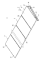
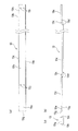
図1は、本発明の構造物設置架台の一実施形態を適用した太陽光発電システムを示す斜視図である。また、図2は、本実施形態の構造物設置架台を示す斜視図である。更に、図3は、本実施形態の構造物設置架台を示す側面図である。 FIG. 1 is a perspective view showing a photovoltaic power generation system to which an embodiment of a structure installation stand of the present invention is applied. FIG. 2 is a perspective view showing the structure installation stand of the present embodiment. Furthermore, FIG. 3 is a side view showing the structure installation stand of the present embodiment.
図1の太陽光発電システム1では、本実施形態の構造物設置架台10を用いて、複数の太陽電池モジュール2を配列し傾斜させて支持している。太陽電池モジュール2は、太陽電池パネル20の周縁を枠部材21により保持したものである。
In the photovoltaic
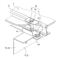
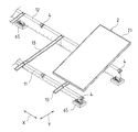
本実施形態の構造物設置架台10では、図2及び図3に示すように複数の縦桟(土台用桟)14を陸屋根等の基礎面に相互に平行に並べて固定し、2本の横桟11、12を各縦桟14と直交するように配して、各横桟11、12を各縦桟14上に載せて固定し、各横桟11、12の天板11a、12a間に梁部材13を架け渡し、梁部材13の一端13aの近傍を一方の横桟11の天板11aに交差させて固定し、この梁部材13の一端13aを横桟11より突出させている。複数の太陽電池モジュール2は、それぞれの梁部材13に重ねられ、各横桟11、12間に架け渡されて搭載される。
In the structure installation stand 10 of this embodiment, as shown in FIGS. 2 and 3, a plurality of vertical beams (base beams) 14 are fixed in parallel with each other on a foundation surface such as a flat roof. 11 and 12 are arranged so as to be orthogonal to the
尚、以降は、横桟11、12の長手方向をX方向(左右方向)とし、このX方向と直交する方向をY方向(前後方向)とする。 Hereinafter, the longitudinal direction of the cross rails 11 and 12 is defined as the X direction (left and right direction), and the direction orthogonal to the X direction is defined as the Y direction (front and back direction).
各縦桟14は、相互に平行に配置されているが、それらの位置が不定である。例えば、陸屋根では、その建築物の建築のときに各縦桟14を固定するための複数のアンカーボルトを設けておくことが可能であるが、その建築物の構造やアンカーボルトの取付け強度等の理由によりアンカーボルトの設置箇所が様々に変わるので、各アンカーボルトの設置箇所を指示したり予測することができない。従って、各縦桟14の設置位置が不定となる。
The
各横桟11、12は、各縦桟14上に載せられて固定される。各横桟11、12の位置により各太陽電池モジュール2の設置位置が決定されるため、各横桟11、12の位置を適宜に調節設定する必要がある。ところが、各縦桟14の設置位置が不定であるため、各横桟11、12の位置を適宜に調節設定するには、各横桟11、12を各縦桟14上の任意の位置に固定することができねばならない。
The
このため、各横桟11、12に固定具15を組み合わせて、各横桟11、12を各縦桟14上の任意の位置に固定し得るような構造を実現している。
For this reason, the structure which can fix each
各横桟11、12は、図1の太陽光発電システム1における各太陽電池モジュール2の配列方向の長さと同一であり、複数の短い桟部材を連結することにより適宜の長さにされている。各桟部材を連結するために、後で述べる専用の連結具を用い、更に固定具15を併用することもある。
The
各横桟11、12の高さは相互に異なり、一方の横桟11が低く、他方の横桟12が高くされている。このような相互に異なる高さの各横桟11、12上に太陽電池モジュール2を搭載して、太陽電池モジュール2を太陽光の入射方向に向くように傾斜させている。従って、各横桟11、12の高低差が大きくなるほど、太陽電池モジュール2の傾斜角が大きくなる。
The heights of the
各横桟11、12の天板11a、12a上には、太陽電池モジュール2の枠部材21の両側を固定支持するための各取付け金具ユニット26又は27が取付けられている。各取付け金具ユニット26は、太陽光発電システム1における相互に隣り合う2枚の太陽電池モジュール2の枠部材21を同時に固定するためのものであり、また各取付け金具ユニット27は、太陽光発電システム1における両外側に位置する太陽電池モジュール2の枠部材21を固定するためのものである。
Mounting
次に、縦桟14、各横桟11、12、固定具15、及び梁部材13等を個別に説明する。
Next, the
図4は、縦桟14、固定具15、及び横桟11を拡大して示す斜視図である。図4に示すように縦桟14は、例えばアルミ材の押出し加工により形成された中空のものであって、その上面14aの中央に嵌合溝14bが形成され、両側面14cにそれぞれの溝14dが形成されている。上面14aの嵌合溝14bは、その底付近が広い幅のガイドとなり、上面14a近くが狭い幅のスリットとなっており、広い幅のガイドでボルトの頭が移動自在に支持され、狭い幅のスリットからボルトの軸部が突出する。また、両側面14cの各溝14dには、係合金具(図示せず)が引っ掛けられ、この係合金具がアンカーボルトで陸屋根等の基礎面に固定され、これにより縦桟14が基礎面に固定支持される。
FIG. 4 is an enlarged perspective view showing the
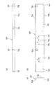
図5(a)、(b)、(c)は、横桟11となる桟部材11Pを示す平面図、背面図、及び側面図である。図5に示すように桟部材11Pは、立設板11cと、立設板11cの底辺及び上辺で同じ側に折り曲げられた底板11b及び天板11aとを有し、ほぼコの字型の断面形状である。底板11bが各縦桟14に架け渡されて載せられ、立設板11cが各縦桟14上に立設される。立設板11c及び天板11aには、各取付け金具ユニット26又は27の取付け位置毎に、これらの取付け金具ユニットを取付けるためのT字型孔11e、位置決めスリット11f、及び長円孔11gが形成されている。また、立設板11cには、一定間隔sで多数の穿孔11hが形成されている。更に、立設板11cの端部近傍で、該端部から一定間隔s未満の箇所にも、複数の穿孔11hが形成されている。
FIGS. 5A, 5 </ b> B, and 5 </ b> C are a plan view, a rear view, and a side view showing a
複数の桟部材11Pは、隣り合う各桟部材11Pの端部を相互に当接させ連結されて、1本の横桟11となる。横桟11においては、隣り合う各桟部材11Pの端部近傍に形成されたそれぞれの穿孔11hが、該各桟部材11Pの連結箇所を挟んで一定間隔sで離間する。すなわち、各桟部材11Pの端部を相互に当接させて連結したときに、各桟部材11Pの端部近傍の穿孔11hが一定間隔sで離間するように該各穿孔11hの位置を設定している。
The plurality of
図6(a)、(b)、(c)は、横桟12となる桟部材12Pを示す平面図、背面図、及び側面図である。図6に示すように桟部材12Pも、桟部材11Pと同様に、立設板12cと、立設板12cの底辺及び上辺で同じ側に折り曲げられた底板12b及び天板12aとを有し、ほぼコの字型の断面形状である。底板12bが各縦桟14に架け渡されて載せられ、立設板12cが各縦桟14上に立設される。立設板12c及び天板12aには、各取付け金具ユニット26又は27を取付けるためのT字型孔12e、位置決めスリット12f、及び長円孔12gが形成されている。また、立設板12cには、一定間隔s(横桟11の立設板11cにおける各穿孔11hの一定間隔sと同一)で複数の穿孔12hが形成されている。更に、立設板12cの端部近傍で、該端部から一定間隔s未満の箇所にも、複数の穿孔12hが形成されている。
FIGS. 6A, 6 </ b> B, and 6 </ b> C are a plan view, a rear view, and a side view showing a
複数の桟部材12Pも、桟部材11Pと同様に、隣り合う各桟部材12Pの端部を相互に当接させ連結されて、1本の横桟12となる。そして、隣り合う各桟部材12Pの端部近傍に形成されたそれぞれの穿孔12hが、該各桟部材12Pの連結箇所を挟んで一定間隔sで離間する。
Similarly to the
尚、各桟部材11P、12Pには、複数種類の長さのものがある。これらの長さの桟部材11P、12Pは、必要とされる各横桟11、12の全長に応じて適宜に組み合わされて連結される。
Note that each of the
図5(c)及び図6(c)から明らかなように各横桟11、12(桟部材11P、12P)の立設板11c、12cは、それぞれの底板11b、12bに対して垂直に立設されている。従って、各底板11b、12bが各縦桟14に載置されたときには、各立設板11c、12cが各縦桟14の上面(土台上面)に対して垂直に立つ。このため、各横桟11、12は、垂直上方向からの耐荷重性に優れ、それぞれの天板11a、12a上にかかる荷重を強固に支持することができる。
As is clear from FIGS. 5C and 6C, the standing
各横桟11、12の天板11a、12aは、それぞれの立設板11c、12cに対する角度が同一鋭角となるように屈曲されている。また、一方の横桟11が低く、他方の横桟12が高くされている。このため、各横桟11、12の底板11b、12bが土台面に載置され、各横桟11、12が規定の間隔を開けて平行に配置された状態では、それぞれの天板11a、12aがほぼ同一傾斜平面上に位置決めされ、これらの天板11a、12aに載置された太陽電池モジュール2がその傾斜平面に沿って配置されて傾斜する。
The
図7に示すように各横桟11、12(桟部材11P、12P)の立設板11c、12cのT字型孔11e、12eは、各立設板11c、12cと各天板11a、12a間の屈曲部(角)から離間して形成されている。このため、各T字型孔11e、12eにより各立設板11c、12cと各天板11a、12a間の屈曲部の強度が低下することはなく、各横桟11、12の強度を維持することができる。
As shown in FIG. 7, the T-shaped
図8は、複数の桟部材11Pを連結するための連結具を示す斜視図である。図8に示すように連結具28は、立設板28aと、立設板28aの上下辺で折り曲げられた底板28b及び天板28cとを有し、ほぼコの字型の断面形状である。立設板28aには、複数の長円孔28d等が形成されており、これらの長円孔28dが桟部材11Pの立設板11cにおける各穿孔11hと重なるように位置決めされている。また、天板28cには、一対の穿孔28eが形成されている。この連結具28は、桟部材11Pのコの字型の断面形状の内側に収められ、その立設板28a、底板28b、及び天板28cが桟部材11Pの立設板11c、底板11b、及び天板11aに重ねられる。
FIG. 8 is a perspective view showing a connector for connecting a plurality of
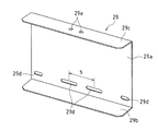
図9は、複数の桟部材12Pを連結するための連結具を示す斜視図である。図9に示すように連結具29は、立設板29aと、立設板29aの上下辺で折り曲げられた底板29b及び天板29cとを有し、ほぼコの字型の断面形状である。立設板29aには、複数の長円孔29d等が形成されており、これらの長円孔29dが桟部材12Pの立設板12cにおける各穿孔12hと重なるように位置決めされている。また、天板29cには、一対の穿孔29eが形成されている。この連結具29は、桟部材12Pのコの字型の断面形状の内側に収められ、その立設板29a、底板29b、及び天板29cが桟部材12Pの立設板12c、底板12b、及び天板12aに重ねられる。
FIG. 9 is a perspective view showing a connector for connecting a plurality of
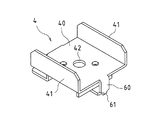
図10(a)、(b)、(c)は、各横桟11、12を縦桟14に固定するための固定具15を示す斜視図、平面図、及び正面図である。図10に示すように固定具15は、基板(基部)15aと、基板15aの一辺を折り曲げて立設した支持板(支持部)15cとを有する。基板15aの他の3辺には、これらの他の3辺を折り曲げて立設したそれぞれのリブ15dが設けられ、これらのリブ15dにより基板15aが補強されている。また、固定具15の支持板15cには、2個のネジ孔15fが形成されている。これらのネジ孔15fの間隔は、各横桟11、12の立設板11c、12cにおける各穿孔11h、12hの一定間隔sと同一である。基板15aの底面から各ネジ孔15fまでの高さは、各横桟11、12の底板11b、12bの底面から各穿孔11h、12hまでの高さと同一である。
FIGS. 10A, 10 </ b> B, and 10 </ b> C are a perspective view, a plan view, and a front view showing a
更に、基板15aには、長形孔15eが形成されている。この長形孔15eの長さaは、支持板15cにおける2個のネジ孔15fの両外側間の距離b(距離b=一定間隔s+(ネジ孔15fの直径))以上に設定されている(a≧b)。
Further, a
図11(a)、(b)、(c)は、梁部材13を示す平面図、側面図、及び正面図である。図11に示すように梁部材13は、主板13b、及び主板13b両側の側板13cからなるほぼコの字型の断面形状を有している。梁部材13の各側板13cは、それらの4箇所で切り欠き13dを形成され、これらの箇所で主板13bが折り曲げられて撓んでいる。
FIGS. 11A, 11 </ b> B, and 11 </ b> C are a plan view, a side view, and a front view showing the
また、梁部材13の一端13aの近傍でも、各側板13cに切り欠き13eが形成され、この一端13aに上方向に屈曲したストッパー13gが設けられている。
Further, also in the vicinity of one
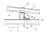
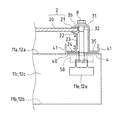
次に、本実施形態の構造物設置架台の構造を詳しく説明する。図12は、本実施形態の構造物設置架台における横桟11近傍を拡大して示す断面図である。また、図13は、本実施形態の構造物設置架台における横桟12近傍を拡大して示す断面図である。
Next, the structure of the structure installation stand of this embodiment will be described in detail. FIG. 12 is an enlarged cross-sectional view showing the vicinity of the
図3、図12、及び図13において、縦桟14は、係合金具やアンカーボルト(図示せず)を用いて、陸屋根等の基礎面に固定される。この縦桟14の嵌合溝14bの広い幅のガイドにボルト16aの頭を挿入して、ボルト16aの軸部を嵌合溝14bの狭い幅のスリットから突出させた状態で、ボルト16aを縦桟14の嵌合溝14bに沿って適宜に移動させて位置調節する。
3, 12, and 13, the
各横桟11、12を縦桟14上に固定するには2個の固定具15を必要とするため、2本のボルト16aを縦桟14の嵌合溝14bに沿ってX方向に移動させて位置調節し、これらのボルト16aを各横桟11、12の間隔で配置する。
In order to fix the
また、図12に示すように横桟11を縦桟14と直交する方向(X方向)に向けて、横桟11を縦桟14上に載せ、X方向及びY方向のいずれについても、横桟11を移動させて位置決めする。この後、2個の固定具15の基板15aの長形孔15eにそれぞれのボルト16aの軸部を通して、各固定具15の基板15aを縦桟14の上面14aに載せ、固定具15毎に、固定具15の支持板15cを横桟11の立設板11cに当接させ、固定具15の支持板15cを縦桟14上でX方向に移動させて、固定具15の支持板15cの2個のネジ孔15fを横桟11の立設板11cの2個の穿孔11hに重ね合わせ、各ボルト17aを横桟11の各穿孔11hを介して固定具15の各ネジ孔15fにねじ込み、固定具15の支持板15cを横桟11の立設板11cに固定する(図4を参照)。更に、断面形状がコの字型の補強金具25の孔にボルト16aの軸部を通して、補強金具25を固定具15の基板15aに重ね、ボルト16aの軸部にナット16bをねじ込んで締め付け、固定具15を縦桟14に締結する。これにより、横桟11が縦桟14に固定される。
Further, as shown in FIG. 12, the
同じく、図13に示すように横桟12を縦桟14と直交する方向(X方向)に向けて、横桟12を縦桟14上に載せ、X方向及びY方向のいずれについても、横桟12を移動させて位置決めする。この後、2個の固定具15の基板15aの長形孔15eにそれぞれのボルト16aの軸部を通して、各固定具15の基板15aを縦桟14の上面14aに載せ、固定具15毎に、固定具15の支持板15cを縦桟14上でX方向に移動させて、固定具15の支持板15cの2個のネジ孔15fを横桟12の立設板12cの2個の穿孔12hに重ね合わせ、各ボルト17aを横桟12の各穿孔12hを介して固定具15の各ネジ孔15fにねじ込み、固定具15の支持板15cを横桟12の立設板12cに固定する。更に、補強金具25を固定具15の基板15aに重ね、ボルト16aの軸部にナット16bをねじ込んで締め付け、固定具15を縦桟14に締結する。これにより、横桟12が縦桟14に固定される。
Similarly, as shown in FIG. 13, the
ここで、X方向における横桟11及び固定具15の位置調節について説明する。横桟11の立設板11cに一定間隔sで多数の穿孔11hを形成し、固定具15の支持板15cに一定間隔sで2個のネジ孔15fを形成していることから、固定具15の支持板15cの各ネジ孔15fが横桟11の立設板11cの2個の穿孔11hに重なり合えば、この重なり合った位置で固定具15の支持板15cを横桟11の立設板11cに締結することができ、横桟11に対する固定具15の締結位置を一定間隔sずつずらして調節することが可能である。
Here, the position adjustment of the
また、固定具15の基板15aに、長さa(a≧b(距離b=一定間隔s+(ネジ孔15fの直径))の長い長形孔15eが形成されており、固定具15の基板15aが該固定具15の基板15aの長形孔15eを通じて縦桟14に締結されることから、固定具15の基板15aを、少なくとも一定間隔sの距離の分だけ移動させることができ、この距離の範囲では固定具15の取付け位置を連続的に調節することができる。
Further, a
従って、縦桟14の位置を基準にすると固定具15の位置を少なくとも一定間隔sの距離の範囲で連続的に調節することができ、かつ固定具15の位置を基準にすると横桟11の位置を一定間隔sずつ調節することができ、両者の調節を組み合わせることにより縦桟14に対する横桟11の位置を該横桟11の長さの分だけ自在に調節設定することができる。
Therefore, when the position of the
縦桟14に対する横桟11の位置調節を容易にするには、固定具15の基板15aの長形孔15eの長さaを距離bよりも十分に長くするのが好ましい(a>b)。これにより、縦桟14に対する固定具15cの連続的な位置調節範囲が広がって、縦桟14に対する横桟11の連続的な位置調節範囲も広がる。
In order to easily adjust the position of the
先に述べたように陸屋根上の各縦桟14の位置が不定であるが、そのように縦桟14に対する横桟11の位置を自在に調節することができるため、各縦桟14上の任意の位置に横桟11を固定することができる。
As described above, the position of each
実際には、横桟11が複数の桟部材11Pを連結したものであるから、桟部材11P別に、固定具15を用いて、桟部材11Pを縦桟14に固定することになるが、それぞれの桟部材11Pに一定間隔sで多数の穿孔11hが形成されているため、いずれの桟部材11Pであっても、縦桟14に対する桟部材11Pの位置を該桟部材11Pの長さの分だけ自在に調節設定することができ、縦桟14上で各桟部材11Pを相互に当接させて、1本の横桟11を形成することができる。
Actually, since the
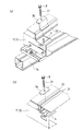
各桟部材11Pの連結箇所では、図14に示すように連結具28を各桟部材11Pのコの字型の断面形状の内側に重ねて、連結具28の各長円孔28dを、各桟部材11Pの連結箇所を挟んで一定間隔sで離間するそれぞれの穿孔11h等に重ね合わせ、複数のボルト18aを各長円孔28d及び各穿孔11hに通して、これらのボルト18aにそれぞれのナット18b(図15に示す)をねじ込んで締め付ける。
As shown in FIG. 14, the connecting
また、図15に示すように各桟部材11Pの連結箇所を縦桟14に固定することがある。この場合は、この連結箇所に連結具28と固定具15を共に配置することになり、各桟部材11Pの立設板11cを連結具28の立設板28aと固定具15の支持板15c間に挟みこんで、連結具28の各長円孔28d、各桟部材11Pの各穿孔11h、及び固定具15の各ネジ孔15fを相互に重ね合わせ、2本のボルト18aを各長円孔28d、各穿孔11hを介して各ネジ孔15fにねじ込んで締め付け、また他の2本のボルト18aを各長円孔28d、各穿孔11hに通して各ナット18bにねじ込んで締め付ける。連結具28と固定具15を併用して、各桟部材11Pを連結すると、この連結箇所の強度が向上する。
Further, as shown in FIG. 15, the connecting portion of each
同じく、横桟12についても、その立設板12cに一定間隔sで多数の穿孔12hを形成し、固定具15の支持板15cに一定間隔sで2個のネジ孔15fを形成していることから、横桟12に対する固定具15の締結位置を一定間隔sずつずらして調節することが可能である。
Similarly, with respect to the
また、固定具15の基板15aを、該基板15aの長形孔15eを通じて縦桟1に締結していることから、少なくとも一定間隔sの距離の分だけ連続的に移動させることができる。
Further, since the
従って、縦桟14の位置を基準にすると固定具15の位置を一定間隔sの距離の範囲で連続的に調節することができ、かつ固定具15の位置を基準にすると横桟12の位置を一定間隔sずつ調節することができ、両者の調節を組み合わせることにより縦桟14に対する横桟12の位置を該横桟12の長さの分だけ自在に調節設定することができる。
Therefore, when the position of the
先に述べたように縦桟14に対する横桟12の位置調節を容易にするには、固定具15の基板15aの長形孔15eの長さaを距離bよりも十分に長くするのが良い(a>b)。
As described above, in order to facilitate the adjustment of the position of the
そのように縦桟14に対する横桟12の位置を自在に調節することができるため、各縦桟14上の任意の位置に横桟12を固定することができる。
As described above, since the position of the
横桟12が複数の桟部材12Pを連結したものであるが、それぞれの桟部材12Pに一定間隔sで多数の穿孔12hが形成されているため、いずれの桟部材12Pであっても、縦桟14に対する桟部材12Pの位置を該桟部材12Pの長さの分だけ自在に調節設定することができ、縦桟14上で各桟部材12Pを相互に当接させることができる。
The
各桟部材12Pの連結箇所では、各桟部材11Pの連結箇所と同様に、連結具29を各桟部材12Pのコの字型の断面形状の内側に重ねて、連結具29の各長円孔29dを、各桟部材12Pの連結箇所を挟んで一定間隔sで離間するそれぞれの穿孔12h等に重ね合わせ、複数のボルト18aを各長円孔29d及び各穿孔12hに通して、これらのボルト18aにそれぞれのナット18bをねじ込んで締め付ける。
In the connection place of each
また、各桟部材12Pの連結箇所を縦桟14に固定する場合は、この連結箇所に連結具29と固定具15を共に配置し、各桟部材12Pの立設板12cを連結具29の立設板29aと固定具15の支持板15c間に挟みこんで、連結具29の各長円孔29d、各桟部材12Pの各穿孔12h、及び固定具15の各ネジ孔15fを相互に重ね合わせ、2本のボルト18aを各長円孔29d、各穿孔12hを介して各ネジ孔15fにねじ込んで締め付け、また他の2本のボルト18aを各長円孔29d、各穿孔12に通して各ナットにねじ込んで締め付ける。これにより、各桟部材12Pの連結箇所の強度が向上する。
In addition, when fixing the connecting part of each
一方、各横桟11、12のいずれについても、X方向の位置調節を行って、各横桟11、12の間隔を調節する。この間隔の調節は、各横桟11、12の複数箇所に、それぞれの梁部材13を掛け渡すことによりなされる。
On the other hand, for each of the
図13に示すように梁部材13の端部13hには、一対の穿孔13iが形成されており、各穿孔13iから規定距離だけ離間した梁部材13の部位にも、一対の穿孔13jが形成されている。
As shown in FIG. 13, a pair of
図2に示すように梁部材13を各横桟11、12に架け渡して載せ、梁部材13を下方に撓ませる。そして、梁部材13の端部13hの各穿孔13iが横桟12の天板12aの各穿孔12iに重なり合い、かつ梁部材13の各穿孔13jが横桟11の天板11aの各穿孔11iに重なり合うように、各横桟11、12を各縦桟14上でY方向に移動させる。これにより、各横桟11、12の間隔が調節される。この後、2本のボルト19aを梁部材13の端部13hの各穿孔13i及び横桟12の天板12aの各穿孔12iに通して、各ボルト19aにそれぞれのナットをねじ込んで締結し、同様に2本のボルト19aを梁部材13の各穿孔13j及び横桟11の天板11aの各穿孔11iに通して、各ボルト19aにそれぞれのナットをねじ込んで締結し、各横桟11、12の間隔を設定する。
As shown in FIG. 2, the
尚、梁部材13を各桟部材11Pの連結箇所と各桟部材12Pの連結箇所に架け渡すことがあるが、連結具28、29の天板28c、29cの各穿孔28e、29eが横桟11、12の天板11a、12aの各穿孔11i、12iに重なるので、梁部材13を取付けるための各穿孔11i、12iが塞がれることはない(図14、図15を参照)。
The
こうしてX方向における各横桟11、12の位置決めを行い、かつY方向における各横桟11、12の間隔を設定した後、先に述べたように固定具15を用いて、各縦桟14上に各横桟11、12を固定する。
After positioning the
この後、太陽電池モジュール2の略中央が梁部材13に重なるように該太陽電池モジュール2を配置して、太陽電池モジュール2を各横桟11、12の天板11a、12a上に架け渡して載せる。先に述べたように梁部材13を下方に撓ませていることから、太陽電池モジュール2の内側のフレーム(図示せず)が梁部材13に接触して浮くようなことはなく、太陽電池モジュール2を各横桟11、12の天板11a、12a上に確実に搭載することができる。各横桟11、12の天板11a、12a上では、太陽電池モジュール2が傾斜するが、太陽電池モジュール2の枠部材21がその傾斜下方の梁部材13のストッパー13gに突き当たるので、各天板11a、12a上で太陽電池モジュール2が位置決めされ、かつ太陽電池モジュール2の滑落が防止される。
Thereafter, the
更に、各取付け金具ユニット26又は27を用いて、各横桟11、12上に太陽電池モジュール2を固定支持する。各取付け金具ユニット26又は27による支持構造の詳細は後で述べる。
Furthermore, the
このように本実施形態の構造物設置架台10では、固定具15の支持板15cに一定間隔sで2個のネジ孔15fを形成し、各横桟11、12の立設板11c、12cに一定間隔sで多数の穿孔11h、12hを形成していることから、各横桟11に対する固定具15の締結位置を一定間隔sずつずらして調節することが可能である。また、固定具15の基板15aが該基板15aの長さa(a≧b)の長形孔15eを通じて縦桟14に締結されることから、固定具15の基板15aを、少なくとも一定間隔sの距離の分だけ移動させることができ、この距離の範囲では固定具15の取付け位置を連続的に調節することができる。従って、縦桟14の位置を基準にすると固定具15の位置を少なくとも一定間隔sの距離の範囲で連続的に調節することができ、かつ固定具15の位置を基準にすると各横桟11、12の位置を一定間隔sずつ調節することができ、よって縦桟14に対する各横桟11、12の位置を該横桟11、12の長さの分だけ自在に調節設定することができる。
Thus, in the structure installation stand 10 of the present embodiment, the two
このため、陸屋根上の各縦桟14の位置が不定であっても、各縦桟14上の任意の位置に各横桟11、12を固定することができる。
For this reason, even if the position of each
また、各横桟11、12がコの字型断面形状であり、固定具15がL字形の断面形状であるため、各横桟11、12及び固定具15にメッキ鋼板等の安価で強度に優れた素材を適用することができる。
Further, since each of the
更に、梁部材13のストッパー13gが横桟11より突出しているので、太陽電池モジュール2の傾斜下方の端部も横桟11より突出する。このため、雨水が太陽電池モジュール2の傾斜下方の端部へと流れて、この端部から滴り落ちたとしても、雨水が横桟11に降りかかることがなく、横桟11の腐食を防止することができる。
Furthermore, since the
次に、構造物設置架台10の各横桟11、12に対する太陽電池モジュール2の枠部材21の取付け構造を説明する。
Next, the attachment structure of the
図1及び図2において、先に述べたように各取付け金具ユニット26は、太陽光発電システム1における相互に隣り合う2枚の太陽電池モジュール2の枠部材21を同時に固定するためのものであり、また各取付け金具ユニット27は、太陽光発電システム1における両側端に位置する太陽電池モジュール2の枠部材21を固定するためのものである。従って、取付け金具ユニット26と取付け金具ユニット27とでは若干構造が異なる。このため、取付け金具ユニット26と取付け金具ユニット27によるそれぞれの取付け構造を別々に説明する。
1 and 2, as described above, each mounting
まず、太陽光発電システム1における相互に隣り合う2枚の太陽電池モジュール2の枠部材21を同時に固定するための取付け金具ユニット26を説明する。
First, the mounting
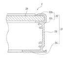
図16に示すように太陽電池モジュール2の枠部材21は、壁部23と、壁部23上側の保持部22と、壁部23の下端から横方向内側に延在する底部片24とを有している。
As shown in FIG. 16, the
保持部22は、一対の保持片22b、22cを有しており、これらの保持片22b、22cの内側に太陽電池パネル20の端部が挟持されている。
The holding
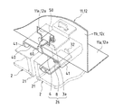
図17及び図18は、横桟11(又は12)に取付けられた取付け金具ユニット26により相互に隣り合う太陽電池モジュール2の端部が固定された状態を上方向から見て示す斜視図である。また、図19は、同状態を下方から見て示す斜視図である。また、図20は、同状態を示す断面図である。
17 and 18 are perspective views showing a state in which the end portions of the
図17〜図20に示すように取付け金具ユニット26は、押圧金具3a、荷重受け金具4、及び該各金具3a、4を相互に締結するボルト8を備えている。荷重受け金具4は、横桟11(又は12)に取付けられて、左右の太陽電池モジュール2の枠部材21の底側を受けている。また、押圧金具3aは、左右の太陽電池モジュール2の枠部材21の表側に当接されている。更に、ボルト8は、押圧金具3aから横桟11(又は12)の天板11a(又は12a)の裏面側まで貫通して、この裏面側で荷重受け金具4にねじ込まれて締結されている。これにより、各金具3a、4間に左右の太陽電池モジュール2の枠部材21が挟み込まれて支持されている。
As shown in FIGS. 17 to 20, the mounting
図21は、押圧金具3aを示す斜視図である。図21に示すように押圧金具3aは、平板状の押圧板31の前後の両端部に下方へと突出する突起片32を形成し、押圧板31の中央部に穿孔33を形成したものである。
FIG. 21 is a perspective view showing the pressing fitting 3a. As shown in FIG. 21, the
押圧板31は、横桟11(又は12)の天板11a(又は12a)上に隣り合って配置された2枚の太陽電池モジュール2の枠部材21を上から押圧するのに用いられる。又、押圧板31の穿孔33は、ボルト8が挿入される孔である。押圧金具3aの突起片32は、左右の太陽電池モジュール2間に挿入され、左右の太陽電池モジュール2間の配置間隔を設定する。
The
図22は、荷重受け金具4を示す斜視図である。図22に示すように荷重受け金具4は、荷重受板40、裏板50、及び荷重受板40と裏板50を結合するジョイント部60を有している。ジョイント部60の途中には、容易に屈曲可能なように括部61が設けられている。
FIG. 22 is a perspective view showing the
裏板50には、その後端縁から垂直に屈曲した後壁50bが形成され、またその前端縁から垂直に屈曲した前壁50aが形成されている。更に、前壁50aの端辺から垂直に屈曲した係合片50cが形成され、この係合片50cに長孔50dが形成されている。
The
荷重受板40の両端縁には、上方に屈曲した爪片41、41が形成されている。また、荷重受板40の後端縁には、下方に屈曲した位置決め片43が形成され、この位置決め片43に係合溝43aが形成されている。
また、荷重受板40の中央部に穿孔42が貫通形成され、裏板50にはネジ孔51が形成されている。荷重受板40の穿孔42には、ボルト8が通され、裏板50のネジ孔51にボルト8がねじ込まれる。
A
図23〜図25に示すように荷重受け金具4のジョイント部60が括部61で折り曲げられて、荷重受板40と裏板50が相互に間隙を開けて対向配置され、裏板50の係合片50cの長孔50dに荷重受板40の位置決め片43が嵌入され、位置決め片43の長孔43aに係合片50cの凸部50eが嵌入されて、荷重受板40と裏板50が相互に係止される。
As shown in FIGS. 23 to 25, the
一方、図5(a)〜(c)及び図6(a)〜(c)に示したように横桟11(又は12)の立設板11c(又は12c)には、取付け金具ユニット26(又は27)を取付けるためのT字型孔11e(又は12e)が形成され、また天板11a(12a)には、取付け金具ユニット26(又は27)を取付けるための位置決めスリット11f(又は12f)、及び長円孔11g(又は12g)が形成されている。
On the other hand, as shown in FIGS. 5A to 5C and FIGS. 6A to 6C, the mounting plate unit 26 (or 12c) is attached to the standing
天板11a(12a)の長円孔11g(又は12g)は、ボルト8を挿入するためのものであり、このボルト8の挿入位置を微調整するために細長い長孔となっている。又、位置決めスリット11f(又は12f)は、荷重受け金具4の位置決め片43を挿入するためのものであり、この荷重受け金具4の位置決め片43の挿入位置を微調整するために細長い長孔となっている。
The
このような横桟11(又は12)に荷重受け金具4を取付けるには、まず図22に示すような折り曲げられる前の荷重受け金具4の裏板50を横桟11(又は12)の立設板11c(又は12c)のT字型孔11e(又は12e)に通して、荷重受け金具4のジョイント部60までをT字型孔11e(又は12e)に挿入する。
In order to attach the
そして、荷重受け金具4のジョイント部60の括部61を90度折り曲げて、裏板50と荷重受板40を天板11a(又は12a)を介して相互に対向配置し、裏板50と荷重受板40間に天板11a(又は12a)を挟持し、荷重受け金具4を天板11a(又は12a)に取付ける。このとき、荷重受け金具4の位置決め片43を天板11a(又は12a)の位置決めスリット11f(又は12f)に挿入して、荷重受け金具4を位置決めする。また、裏板50の係合片50cの長孔50dに荷重受板40の位置決め片43を嵌入し、位置決め片43の長孔43aに係合片50cの凸部50eを嵌入して、荷重受板40と裏板50を相互に係止させる。
Then, the
こうして荷重受け金具4を天板11a(又は12a)に取付けた状態で、図20に示すように荷重受け金具4の荷重受板40の中央付近から左側の爪片41までのスペースに左側太陽電池モジュール2の枠部材21の底部片24を差し入れて配置し、また荷重受板40の中央付近から右側の爪片41までのスペースに右側太陽電池モジュール2の枠部材21の底部片24を差し入れて配置し、各太陽電池モジュール2の枠部材21の保持部22上に押圧金具3aを載せて、押圧金具3aの突起片32を左右の太陽電池モジュール2間に挿入し、ボルト8を押圧金具3aの穿孔33及び荷重受板40の穿孔42に挿入して、ボルト8を天板11a(又は12a)の長円孔11g(又は12g)を通じて裏板50のネジ孔51へとネジ込み、ボルト8を締め付ける。これにより、荷重受け金具4と押圧金具3a間に左右の太陽電池モジュール2の枠部材21が挟み込まれて固定支持される。
With the
次に、太陽光発電システム1における両側端に位置する太陽電池モジュール2の枠部材21を固定するための取付け金具ユニット27を説明する。
Next, the mounting
図26及び図27は、横桟11(又は12)に取付けられた取付け金具ユニット27により左右の太陽電池モジュール2の端部が固定された状態を上方向から見て示す斜視図である。また、図28は、同状態を示す断面図である。
26 and 27 are perspective views showing a state in which the ends of the left and right
図26〜図28に示すように取付け金具ユニット27は、押圧金具3b、荷重受け金具4、及び各金具3b、4を相互に締結するボルト8を備えている。荷重受け金具4は、取付け金具ユニット26の荷重受け金具4と同様の構成であり、横桟11(又は12)への取付け構造もしくは手順も同様である。また、押圧金具3bは、1枚の太陽電池モジュール2の枠部材21の表側に当接している。更に、ボルト8は、押圧金具3bから横桟11(又は12)の天板11a(又は12a)の裏側面へと貫通して、この裏面側で荷重受け金具4にねじ込まれて締結されている。これにより、各金具3b、4間に1枚の太陽電池モジュール2の枠部材21が挟み込まれて支持されている。
As shown in FIGS. 26 to 28, the mounting
図29は、押圧金具3bを示す斜視図である。図29に示すように押圧金具3bは、平板状の押圧板31の前後の両端部に下方へと突出する突起片32を形成し、押圧板31の中央部に穿孔33を形成し、押圧板31の一端縁から垂直に屈曲した立壁34を形成し、立壁34の下端縁から横向きに屈曲した底部片35を形成したものである。
FIG. 29 is a perspective view showing the pressing metal fitting 3b. As shown in FIG. 29, the press fitting 3b is formed with protruding
図28に示すように荷重受け金具4の荷重受板40の中央付近から内側の爪片41までのスペースに左側又は右側の太陽電池モジュール2の枠部材21の底部片24を差し入れて配置し、また荷重受板40の中央付近から外側の爪片41までのスペースに押圧金具3bの底部片35を配置し、太陽電池モジュール2の枠部材21の保持部22上に押圧金具3bの押圧板31を載せて、押圧金具3bの突起片32を太陽電池モジュール2の保持部22に押し当てて、太陽電池モジュール2を位置決めし、ボルト8を押圧金具3bの穿孔33及び荷重受け金具4の荷重受板40の穿孔42に挿入して、ボルト8を天板12の長円孔13を通じて裏板50のネジ孔51へとネジ込み、ボルト8を締め付ける。これにより、荷重受け金具4と押圧金具3b間に太陽電池モジュール2の枠部材21が挟み込まれて固定支持される。
28, the
次に、図1の太陽光発電システム1の施工手順を説明する。図30A〜図30Cを参照しつつ説明する。
Next, the construction procedure of the photovoltaic
まず、図30Aに示すように複数の縦桟14の長手方向をY方向に向けて、これらの縦桟14を陸屋根等の基礎面上に相互に平行に配置して固定する。これらの縦桟14の間隔及び位置は不定である。
First, as shown in FIG. 30A, the longitudinal direction of the plurality of
縦桟14毎に、その嵌合溝14bに2本のボルト16aの頭を挿通して、ボルト16aの軸部を嵌合溝14bの狭い幅のスリットから突出させた状態で、ボルト16aを各横桟11、12の間隔で配置する。
For each
各横桟11、12を各縦桟14と直交する方向(X方向)に向けて、各横桟11、12を各縦桟14上に載せ、各横桟11、12をX方向に移動させて位置決めする。
The
また、各横桟11、12の複数箇所に、それぞれの梁部材13を掛け渡して、各横桟11、12の間隔を調節する。
In addition, the
図30Bに示すように各固定具15の基板15aの長形孔15eにそれぞれのボルト16aの軸部を通して、各固定具15の基板15aを縦桟14の上面14aに載せ、固定具15毎に、固定具15の支持板15cを横桟11(又は12)の立設板11c(又は12c)に当接させ、固定具15の支持板15cの各ネジ孔15fを横桟11(又は12)の各穿孔11h(又は12h)に重ね合わせ、ボルト及びナットを用いて、横桟11(又は12)の立設板11c(又は12c)を固定具15の支持板15cに締結する。また、固定具15毎に、補強金具25を固定具15の基板15aに重ね、ボルト16aの軸部にナット16bをねじ込んで締め付け、固定具15を縦桟14に締結する。
As shown in FIG. 30B, the
これにより、各横桟11、12が各縦桟14上で規定の間隔を開けて平行に配置されて固定され、それぞれの天板11a、12aがほぼ同一傾斜平面上に位置決めされる。
As a result, the
また、荷重受け金具4の裏板50を横桟11(又は12)のT字型孔11e(又は12e)に通して、荷重受け金具4のジョイント部60までをT字型孔11e(又は12e)に挿入し、荷重受け金具4の位置決め片43を天板11a(又は12a)の位置決めスリット11f(又は12f)に挿入して、荷重受け金具4の位置決めを行う。そして、荷重受け金具4のジョイント部60の括部61を90度折り曲げて、裏板50と荷重受板40を天板11a(又は12a)を介して相互に対向配置し、荷重受け金具4を天板11a(又は12a)に取付ける。
Further, the
この荷重受け金具4は、太陽電池モジュール2毎に、太陽電池モジュール2の枠部材21の両側4箇所を固定するべく、各横桟11、12のそれぞれの箇所に取付けられる。
For each
次に、図30Cに示すように複数の太陽電池モジュール2を各横桟11、12上に配置し、太陽電池モジュール2毎に、太陽電池モジュール2の枠部材21の両側4箇所を各横桟11、12上の4個の荷重受け金具4に載せ、太陽電池モジュール2の傾斜下方の端部を梁部材13のストッパー13gに当接させて、太陽電池モジュール2を位置決めする。これにより、太陽電池モジュール2が各横桟11、12の天板11a、12aに沿って傾斜して支持される。
Next, as shown in FIG. 30C, a plurality of
そして、太陽光発電システム1における両側端に位置する太陽電池モジュール2の枠部材21については、図31(a)に示すように押圧金具3bの押圧板31を太陽電池モジュール2の枠部材21上に載せて、ボルト8を押圧金具3bから横桟11(又は12)の天板11a(又は12a)の裏側面へと貫通させて荷重受け金具4の裏板50にねじ込んで締め付け、荷重受け金具4と押圧金具3b間に太陽電池モジュール2の枠部材21を挟み込んで固定支持する。
And about the
また、相互に隣り合う2枚の太陽電池モジュール2の枠部材21については、図31(b)に示すように押圧金具3aを各太陽電池モジュール2の枠部材21上に載せて、ボルト8を押圧金具3aから横桟11(又は12)の天板11a(又は12a)の裏側面へと貫通させて荷重受け金具4の裏板50にねじ込んで締め付け、荷重受け金具4と押圧金具3a間に左右の太陽電池モジュール2の枠部材21を挟み込んで固定支持する。
Moreover, about the
この結果、図1に示すような太陽光発電システム1が構築される。
As a result, a photovoltaic
尚、本発明は、上記実施形態に限定されるものではなく、多様に変形することができる。例えば、図32に示すように太陽電池モジュール2を複数列で設け、各列の太陽電池モジュール2の傾きを隣同士の列で相互に逆にして、各列の太陽電池モジュール2を山型に配置してもよい。この山型の配置のために、高い方の各横桟12を相互に近づけて2列で配置し、この2列の外側に低い方のそれぞれの横桟11を配置し、各横桟11、12上に複数の太陽電池モジュール2を搭載する。
In addition, this invention is not limited to the said embodiment, It can deform | transform variously. For example, as shown in FIG. 32, the
このような太陽電池モジュール2の配置により、多数の太陽電池モジュール2を近接配置しても、太陽電池モジュール2の影に他の太陽電池モジュール2が入ることが無く、発電効率を高くすることができる。
With such an arrangement of the
また、横桟11又は12に、図33に示すような間隔で各穿孔11h、12hを形成しても構わない。ここでは、固定具15の支持板15の各ネジ孔15fに重なり合う一定間隔sの2個の穿孔11h又は12hを一組とすると、横桟11又は12の長手方向に沿って、複数組の穿孔11h又は12hを形成している。いずれの組においても2個の穿孔11h又は12hが一定間隔sで離間しているが、相互に隣り合う各組の穿孔11hの間隔qが一定間隔s未満であって狭くなっている。この場合は、固定具15の支持板15cにおける各ネジ孔15fを横桟11又は12におけるいずれかの組の各穿孔11h又は12hに重ねて、固定具15の支持板15cを横桟11又は12に締結することができる。また、固定具15の基板15aの長形孔15eの長さaを支持板15における各ネジ孔15fの両外側間の距離bよりも十分に長くすれば(a=b+q)、縦桟14に対する横桟11又は12の位置を該横桟11又は12の長さの分だけ自在に調節設定することができる。
Further, the
また、本実施形態の構造物設置架台では、太陽電池モジュールを支持しいているが、この代わりに、太陽熱発電に用いられる反射鏡パネルを支持してもよい。これにより、太陽熱発電システムを構築することができる。 Moreover, although the solar cell module is supported in the structure installation stand of this embodiment, you may support the reflector panel used for solar power generation instead. Thereby, a solar thermal power generation system can be constructed.
1 太陽光発電システム
2 太陽電池モジュール
3a、3b 押圧金具
4 荷重受け金具
10 構造物設置架台
11、12 横桟(桟)
13 梁部材
14 縦桟(土台用桟)
15 固定具
15a 基板(基部)
15c 支持板(支持部)
28、29 連結板
20 太陽電池パネル
21 枠部材
26、27 取付け金具ユニット
DESCRIPTION OF
13
15
15c Support plate (support part)
28, 29 Connecting
Claims (11)
前記固定具は、前記桟に取付けられたときに該桟に沿って離間する少なくとも2個の穿孔が形成された支持部と、前記各穿孔の両外側間の距離以上に長い長形孔が形成された基部とを有し、
前記桟は、前記固定具の支持部における各穿孔に重なり合うそれぞれの穿孔を一組とすると、この桟の長手方向に沿って形成された複数組の穿孔を有し、
前記固定具の支持部と前記桟を、相互に重ね合わされた該固定具の支持部の各穿孔と該桟の各穿孔を通じて締結し、前記固定具の基部を該固定具の長形孔を通じて前記土台に締結したことを特徴とする構造物設置架台。 A crosspiece on which the structure is mounted and a fixture for fixing the crosspiece to the base,
The fixing device has a support portion formed with at least two perforations that are separated along the crosspiece when attached to the crosspiece, and a long hole that is longer than a distance between both outer sides of the perforations. And a base
The crosspiece has a plurality of sets of perforations formed along the longitudinal direction of the crosspiece, each set of perforations overlapping the perforations in the support portion of the fixture.
The support part of the fixing tool and the crosspiece are fastened through the perforations of the support part of the fixing tool and the perforations of the crosspiece, and the base part of the fixing tool is passed through the elongated hole of the fixing tool. A structure installation stand characterized by being fastened to the base.
前記桟は、前記土台に対して立設される立設板を有し、前記立設板に前記桟の長手方向に沿って複数組の各穿孔を形成したことを特徴とする構造物設置架台。 The structure installation stand according to claim 1,
The crosspiece has a standing plate erected with respect to the base, and a plurality of sets of perforations are formed in the standing plate along the longitudinal direction of the crosspiece. .
前記桟は、複数の桟部材を連結して形成され、
連結箇所で隣り合う2本の前記桟部材には、前記連結箇所を挟んで前記固定具の支持部の各穿孔に重なり合うそれぞれの穿孔を形成したことを特徴とする構造物設置架台。 The structure installation stand according to claim 1,
The crosspiece is formed by connecting a plurality of crosspiece members,
The structure installation stand according to claim 2, wherein each of the two crosspiece members adjacent to each other at a connecting portion is formed with a perforation that overlaps each of the perforations of the support portion of the fixture with the connecting portion interposed therebetween.
前記固定具の支持部の各穿孔に重なり合うそれぞれの穿孔を形成した連結具を備え、
前記2本の桟部材と前記連結具を、相互に重ね合わされた該各桟部材の穿孔及び該連結具の各穿孔を通じて締結し、前記2本の桟部材を前記連結具を介して連結したことを特徴とする構造物設置架台。 The structure installation stand according to claim 3,
A coupling tool having respective perforations that overlap each perforation of the support portion of the fixture;
The two cross members and the connector are fastened through the perforations of the cross members overlapped with each other and the perforations of the connector, and the two cross members are connected via the connector. A structure installation stand characterized by
前記2本の桟部材の連結箇所を前記固定具の支持部と前記連結具間に挟み込み、前記2本の桟部材、前記固定具の支持部、及び前記連結具を、相互に重ね合わされた該各桟部材の穿孔、該固定具の支持部の各穿孔、及び該連結具の各穿孔を通じて締結し、前記2本の桟部材を前記固定具及び前記連結具を介して連結したことを特徴とする構造物設置架台。 The structure installation stand according to claim 4,
The connecting part of the two cross members is sandwiched between the support part of the fixing tool and the connecting tool, and the two cross member members, the support part of the fixing tool, and the connecting tool are overlapped with each other. The two crosspiece members are fastened through the perforations of the crosspiece members, the perforations of the support portion of the fixing tool, and the perforations of the connecting tool, and the two crosspiece members are connected via the fixing tool and the connecting tool. Structure installation stand.
前記桟は、底板、底板の一辺で屈曲され立設された立設板、及び立設板の上辺で屈曲された天板を有し、
2本の前記桟を相互に平行に配置し、前記固定具を用いて、前記各桟の立設板を土台にそれぞれ固定し、構造物を前記各桟の天板上に架け渡して搭載したことを特徴とする構造物設置架台。 It is a structure installation stand as described in any one of Claims 1-5,
The crosspiece has a bottom plate, a standing plate bent and installed on one side of the bottom plate, and a top plate bent on the upper side of the standing plate,
The two crosspieces are arranged in parallel to each other, and the standing plate of each of the crosspieces is fixed to the base using the fixture, and the structure is mounted on the top plate of each of the crosspieces. A structure installation stand characterized by that.
土台に固定された前記各桟の高さが相互に異なり、前記各桟の天板がほぼ同一傾斜平面上に存在し、前記各桟部材の天板上に構造物が傾斜して搭載されたことを特徴とする構造物設置架台。 It is a structure installation stand of Claim 6, Comprising:
The heights of the crosspieces fixed to the base are different from each other, the top plates of the crosspieces exist on substantially the same inclined plane, and the structure is inclined and mounted on the top plates of the crosspiece members. A structure installation stand characterized by that.
前記各桟間に架け渡され固定された梁部材を備え、
前記梁部材の一端側のストッパーは、前記各桟の天板上に載せられた構造物の傾斜下方にあって、前記構造物の一辺を受け止めるように設けられたことを特徴とする構造物設置架台。 The structure installation stand according to claim 7,
A beam member spanned between and fixed to each of the crosspieces,
A stopper on one end side of the beam member is provided below the inclined structure of the structure placed on the top plate of each of the crosspieces so as to receive one side of the structure. Mount.
前記土台は、前記桟と直交する方向に延びる土台用桟であり、
前記固定具の基部を該基部の長形孔を通じて前記土台用桟に締結したことを特徴とする構造物設置架台。 It is a structure installation stand as described in any one of Claims 1-8,
The base is a base rail extending in a direction orthogonal to the rail,
A structure installation stand, wherein a base portion of the fixture is fastened to the base rail through a long hole of the base portion.
前記固定具は、前記桟に取付けられたときに該桟に沿って離間する少なくとも2個の穿孔が形成された支持部と、前記各穿孔の両外側間の距離以上に長い長形孔が形成された基部とを有し、
前記桟は、前記固定具の支持部における各穿孔に重なり合うそれぞれの穿孔を一組とすると、この桟の長手方向に沿って形成された複数組の穿孔を有することを特徴とする構造物設置用支持具。 It has a cross and a fixture,
The fixing device has a support portion formed with at least two perforations that are separated along the crosspiece when attached to the crosspiece, and a long hole that is longer than a distance between both outer sides of the perforations. And a base
The crosspiece has a plurality of sets of perforations formed along the longitudinal direction of the crosspieces, where each of the perforations overlapping the perforations in the support portion of the fixture is set as one set. Support tool.
Priority Applications (3)
| Application Number | Priority Date | Filing Date | Title |
|---|---|---|---|
| JP2009295136A JP4688951B1 (en) | 2009-12-25 | 2009-12-25 | Structure installation stand, structure installation support, and solar power generation system |
| PCT/JP2010/073611 WO2011078382A1 (en) | 2009-12-25 | 2010-12-27 | Structure installation mount, support for structure installation, and solar power generation system |
| US13/519,014 US20120285515A1 (en) | 2009-12-25 | 2010-12-27 | Structure installation mount, support device for structure installation, and solar photovoltaic system |
Applications Claiming Priority (1)
| Application Number | Priority Date | Filing Date | Title |
|---|---|---|---|
| JP2009295136A JP4688951B1 (en) | 2009-12-25 | 2009-12-25 | Structure installation stand, structure installation support, and solar power generation system |
Publications (2)
| Publication Number | Publication Date |
|---|---|
| JP4688951B1 true JP4688951B1 (en) | 2011-05-25 |
| JP2011132780A JP2011132780A (en) | 2011-07-07 |
Family
ID=44193900
Family Applications (1)
| Application Number | Title | Priority Date | Filing Date |
|---|---|---|---|
| JP2009295136A Expired - Fee Related JP4688951B1 (en) | 2009-12-25 | 2009-12-25 | Structure installation stand, structure installation support, and solar power generation system |
Country Status (3)
| Country | Link |
|---|---|
| US (1) | US20120285515A1 (en) |
| JP (1) | JP4688951B1 (en) |
| WO (1) | WO2011078382A1 (en) |
Cited By (5)
| Publication number | Priority date | Publication date | Assignee | Title |
|---|---|---|---|---|
| WO2013011765A1 (en) * | 2011-07-21 | 2013-01-24 | シャープ株式会社 | Installation structure for solar cell module, installation method for solar cell module, and solar photovoltaic power generation system |
| JP2013024031A (en) * | 2012-09-06 | 2013-02-04 | Sharp Corp | Solar cell module installation structure and method, and photovoltaic power generation method |
| US20140008312A1 (en) * | 2012-07-06 | 2014-01-09 | Max W. Durney | Solar panel rack |
| US9166526B2 (en) | 2013-07-03 | 2015-10-20 | Industrial Origami, Inc. | Solar panel rack |
| CN107477053A (en) * | 2017-09-19 | 2017-12-15 | 中广核研究院有限公司 | Height support beam auxiliary member |
Families Citing this family (34)
| Publication number | Priority date | Publication date | Assignee | Title |
|---|---|---|---|---|
| EP2678492B1 (en) * | 2011-02-22 | 2020-09-02 | Tesla, Inc. | Mounting system and method for photovoltaic modules |
| US8870139B1 (en) | 2011-03-01 | 2014-10-28 | Jonathan Port | Strap mount for solar panels |
| US20150377521A1 (en) * | 2011-03-01 | 2015-12-31 | Jonathan Port | Strap mount for solar panels |
| JP2013029005A (en) * | 2011-07-29 | 2013-02-07 | Daimaru Sogo Kikaku Kk | Method and structure for installing solar panel |
| US9038329B2 (en) * | 2011-10-11 | 2015-05-26 | Sunlink Corporation | Structure following roof mounted photovoltaic system |
| WO2013084837A1 (en) * | 2011-12-06 | 2013-06-13 | 伊藤組土建株式会社 | Solar power system and solar panel installation method |
| JP5930695B2 (en) * | 2011-12-16 | 2016-06-08 | 旭化成ホームズ株式会社 | Function panel fixture |
| ITVI20120008A1 (en) * | 2012-01-12 | 2013-07-13 | Js Srl | FIXING DEVICE FOR PANELS, IN PARTICULAR FOR SOLAR THERMAL OR PHOTOVOLTAIC PANELS. |
| JP5912797B2 (en) * | 2012-04-16 | 2016-04-27 | 三甲株式会社 | Solar panel device and manufacturing method thereof |
| AU2013280828B2 (en) * | 2012-06-25 | 2017-03-09 | Sunpower Corporation | Brace for solar module array |
| US8683761B2 (en) * | 2012-06-25 | 2014-04-01 | Sunpower Corporation | Mounting system for solar module array |
| US9498854B2 (en) | 2012-06-25 | 2016-11-22 | Sunpower Corporation | Anchor for solar module |
| US9010041B2 (en) | 2012-06-25 | 2015-04-21 | Sunpower Corporation | Leveler for solar module array |
| US9193014B2 (en) | 2012-06-25 | 2015-11-24 | Sunpower Corporation | Anchor for solar module |
| US9316417B2 (en) * | 2012-06-29 | 2016-04-19 | Sunpower Corporation | Framing system for mounting solar collecting devices |
| JP2014047570A (en) * | 2012-08-31 | 2014-03-17 | Yasuhiro Nomura | Fixture for solar panels |
| US9742347B2 (en) | 2013-02-11 | 2017-08-22 | Jonathan Port | Modular strap mount for solar panels |
| CA2830914C (en) * | 2013-10-11 | 2018-06-26 | Polar Racking Inc. | Support racking for solar panel |
| WO2015066595A1 (en) * | 2013-11-01 | 2015-05-07 | Handy & Harman | Rail-based roof attachment and load distribution system |
| US20150372635A1 (en) * | 2014-06-23 | 2015-12-24 | Miguel M.L. Praca | Modular roof mounting system for photovoltaic panels |
| USD739346S1 (en) * | 2014-12-09 | 2015-09-22 | Bentek Corporation | Inverter power rack and power skid |
| USD739819S1 (en) * | 2014-12-09 | 2015-09-29 | Bentek Corporation | Inverter power rack and power skid |
| CN105227066A (en) * | 2015-10-29 | 2016-01-06 | 苏州爱康金属科技有限公司 | Photovoltaic generating system waterborne |
| CN105207582A (en) * | 2015-10-29 | 2015-12-30 | 苏州爱康金属科技有限公司 | Photovoltaic bracket of waterborne photovoltaic power generation system |
| CN105227070B (en) * | 2015-10-29 | 2018-06-05 | 苏州爱康金属科技有限公司 | The basis of photovoltaic power generation apparatus waterborne |
| US10720877B2 (en) * | 2016-02-25 | 2020-07-21 | Solarcity Corporation | Photovoltaic mounting system for solar tracker array |
| US9628019B1 (en) * | 2016-09-09 | 2017-04-18 | Polar Racking Inc. | Photovoltaic panel racking system |
| JP6396976B2 (en) * | 2016-12-08 | 2018-09-26 | 東光電気工事株式会社 | Photovoltaic power generation device and method for manufacturing solar power generation device |
| CN106542023B (en) * | 2016-12-11 | 2022-04-15 | 河北工业大学 | Small-sized vehicle lock pile using solar energy as power source |
| DE102017102827B3 (en) * | 2017-02-13 | 2018-06-21 | Mounting Systems Gmbh | Carrier device with C-profile module carrier for solar modules |
| JP7011404B2 (en) * | 2017-05-24 | 2022-01-26 | 日栄インテック株式会社 | Folded plate roof stand |
| CN112335174A (en) * | 2018-03-26 | 2021-02-05 | 索尔坡德私人有限公司 | System for mounting service components to building structures |
| US10797635B2 (en) | 2018-08-29 | 2020-10-06 | Nextracker Inc. | Solar module mounting bracket assemblies |
| CN109882710A (en) * | 2019-03-08 | 2019-06-14 | 广西梧州制药(集团)股份有限公司 | A kind of four-way wind speed measuring apparatus and method |
Family Cites Families (29)
| Publication number | Priority date | Publication date | Assignee | Title |
|---|---|---|---|---|
| US4044517A (en) * | 1976-07-12 | 1977-08-30 | Kaiser Aluminum & Chemical Corporation | Insulated tank jacketing system |
| GB8507191D0 (en) * | 1985-03-20 | 1985-04-24 | Cladcolor Profiling Ltd | Support system |
| US4733986A (en) * | 1985-08-08 | 1988-03-29 | Square D Company | Splice plate for cable tray |
| WO1996007803A1 (en) * | 1994-09-08 | 1996-03-14 | Non-Compact, Inc. | System for mounting building panels |
| US5715634A (en) * | 1995-06-07 | 1998-02-10 | Sps Corporation | Skylight construction |
| JPH11124971A (en) * | 1997-10-23 | 1999-05-11 | Eishin:Kk | Support metal fitting of rooftop member |
| US6065255A (en) * | 1998-12-07 | 2000-05-23 | Kyocera Solar, Inc. | Roof mounting for photovoltaic modules |
| US6227330B1 (en) * | 1999-07-15 | 2001-05-08 | Mark A. Preusser | Support structure for suspending a work surface below a girder |
| JP2002021242A (en) * | 2000-07-10 | 2002-01-23 | Sekisui Chem Co Ltd | Staging installing structure |
| DK1300523T3 (en) * | 2000-07-12 | 2014-06-23 | Kaneka Corp | Solar cell battery module, solar cell battery module installation design, tag with current generating function of the installation structure and method of installing solar cell battery module |
| US6414237B1 (en) * | 2000-07-14 | 2002-07-02 | Astropower, Inc. | Solar collectors, articles for mounting solar modules, and methods of mounting solar modules |
| WO2002041407A1 (en) * | 2000-11-16 | 2002-05-23 | Kaneka Corporation | Solar battery module, photovoltaic power generation system, support block supporting solar battery module, and photovoltaic power generation system installation method |
| US7574842B2 (en) * | 2002-04-11 | 2009-08-18 | Schott Solar, Inc. | Apparatus for mounting photovoltaic power generating systems on buildings |
| JP4078399B2 (en) * | 2002-12-25 | 2008-04-23 | 沖縄電力株式会社 | Installation structure of solar cell module |
| JP3907668B2 (en) * | 2005-04-07 | 2007-04-18 | シャープ株式会社 | Mounting structure of solar cell module |
| WO2007079382A2 (en) * | 2005-12-28 | 2007-07-12 | Sunpower Corporation, Systems | Supported pv module assembly |
| US7836639B2 (en) * | 2006-04-20 | 2010-11-23 | Sharp Kabushiki Kaisha | Structure mounting and supporting device and method |
| DE202006016382U1 (en) * | 2006-10-20 | 2007-02-15 | Hoeft, Duhay, Kempkensteffen GbR (vertretungsberechtigter Gesellschafter: Herr Klaus-Dieter Hoeft, 33332 Gütersloh) | Solar module assembly mounted on flat roof, comprises frame of triangular cross section supporting sloping solar panels and sheet metal covering |
| JP4290750B2 (en) * | 2007-06-11 | 2009-07-08 | 株式会社屋根技術研究所 | Solar cell module fixing structure, solar cell module frame and fixing member |
| US20110198304A1 (en) * | 2008-05-01 | 2011-08-18 | Linus Eric Wallgren | Rack Assembly for Solar Energy Collecting Module |
| US8250829B2 (en) * | 2008-05-22 | 2012-08-28 | Mainstream Energy Corporation | Module attachment apparatus |
| US20100089390A1 (en) * | 2008-10-13 | 2010-04-15 | Sunlink, Corp | Solar array mounting system |
| US8276330B2 (en) * | 2008-12-12 | 2012-10-02 | Applied Energy Technologies | Modular solar panel racking system |
| JP4637231B2 (en) * | 2008-12-15 | 2011-02-23 | シャープ株式会社 | Solar cell module installation stand |
| US9057542B2 (en) * | 2009-04-27 | 2015-06-16 | Unirac, Inc. | Snap-on structural connector |
| JP4365450B1 (en) * | 2009-05-01 | 2009-11-18 | 株式会社屋根技術研究所 | Solar cell module fixing structure, solar cell module frame and fixing member |
| US8413944B2 (en) * | 2009-05-01 | 2013-04-09 | Applied Energy Technologies | Mounting systems for solar panels |
| US8316618B1 (en) * | 2011-07-07 | 2012-11-27 | Solon Corporation | Integrated photovoltaic rooftop modules |
| US8387319B1 (en) * | 2011-09-02 | 2013-03-05 | Opsun Systems Inc. | Solar panel securing assembly for sheet metal sloping roofs |
-
2009
- 2009-12-25 JP JP2009295136A patent/JP4688951B1/en not_active Expired - Fee Related
-
2010
- 2010-12-27 WO PCT/JP2010/073611 patent/WO2011078382A1/en active Application Filing
- 2010-12-27 US US13/519,014 patent/US20120285515A1/en not_active Abandoned
Cited By (9)
| Publication number | Priority date | Publication date | Assignee | Title |
|---|---|---|---|---|
| WO2013011765A1 (en) * | 2011-07-21 | 2013-01-24 | シャープ株式会社 | Installation structure for solar cell module, installation method for solar cell module, and solar photovoltaic power generation system |
| JP2013023926A (en) * | 2011-07-21 | 2013-02-04 | Sharp Corp | Solar cell module installation structure and method, and photovoltaic power generation system |
| US20140008312A1 (en) * | 2012-07-06 | 2014-01-09 | Max W. Durney | Solar panel rack |
| US8936164B2 (en) * | 2012-07-06 | 2015-01-20 | Industrial Origami, Inc. | Solar panel rack |
| US9166521B2 (en) | 2012-07-06 | 2015-10-20 | Industrial Origami, Inc. | Solar panel rack |
| US9425731B2 (en) | 2012-07-06 | 2016-08-23 | Industrial Origami, Inc. | Solar panel rack |
| JP2013024031A (en) * | 2012-09-06 | 2013-02-04 | Sharp Corp | Solar cell module installation structure and method, and photovoltaic power generation method |
| US9166526B2 (en) | 2013-07-03 | 2015-10-20 | Industrial Origami, Inc. | Solar panel rack |
| CN107477053A (en) * | 2017-09-19 | 2017-12-15 | 中广核研究院有限公司 | Height support beam auxiliary member |
Also Published As
| Publication number | Publication date |
|---|---|
| WO2011078382A1 (en) | 2011-06-30 |
| US20120285515A1 (en) | 2012-11-15 |
| JP2011132780A (en) | 2011-07-07 |
Similar Documents
| Publication | Publication Date | Title |
|---|---|---|
| JP4688951B1 (en) | Structure installation stand, structure installation support, and solar power generation system | |
| JP4637231B2 (en) | Solar cell module installation stand | |
| JP5680242B2 (en) | SOLAR CELL MODULE MOUNTING STRUCTURE, SOLAR CELL DEVICE, AND SOLAR CELL MODULE MOUNTING METHOD | |
| US9551510B2 (en) | Slider clip and photovoltaic structure mounting system | |
| JP4979760B2 (en) | Solar cell module mount and solar power generation system using the solar cell module mount | |
| JP2008214875A (en) | Mounting structure of solar cell module | |
| WO2011129321A1 (en) | Solar cell module support structure, method of constructing said support structure, and solar photovoltaic power generation system using said support structure | |
| JP4202401B1 (en) | Structure installation stand, its assembling method, solar cell module, and construction structure using structure installation stand | |
| WO2011099564A1 (en) | Structure-supporting structure, frame for structure, method for constructing structure using said frame, and solar power generating system | |
| JP2010261257A (en) | Structure for fixing solar cell module | |
| JP5388880B2 (en) | Solar cell module fixing structure, solar cell module mount, solar cell module construction method, and solar cell power generation system | |
| JP2015220845A (en) | Cradle for solar panel | |
| KR101090318B1 (en) | Assembly For Installing Photovoltaic Power Generation | |
| JP2013007192A (en) | Fitting structure for solar battery and the like to be mounted on roof | |
| JP5916096B2 (en) | Installation structure of solar energy utilization equipment | |
| JP2017066806A (en) | Installation structure, installation method of solar cell module, and photovoltaic power generation system using installation structure of the same | |
| JP3934453B2 (en) | Roof structure with solar panel | |
| JP6021579B2 (en) | Solar cell module support structure and solar cell module installation method | |
| JP7304664B1 (en) | Solar panel mounting frame, solar panel system and solar panel mounting method | |
| KR101124440B1 (en) | Installation method of solar sell module | |
| JP2023115648A (en) | Solar panel fixing structure | |
| JP2003082823A (en) | Fixing method and fixing structure of solar heat collector | |
| JP2017008520A (en) | Solar panel fixture |
Legal Events
| Date | Code | Title | Description |
|---|---|---|---|
| TRDD | Decision of grant or rejection written | ||
| A01 | Written decision to grant a patent or to grant a registration (utility model) |
Free format text: JAPANESE INTERMEDIATE CODE: A01 |
|
| R150 | Certificate of patent or registration of utility model |
Free format text: JAPANESE INTERMEDIATE CODE: R150 |
|
| FPAY | Renewal fee payment (event date is renewal date of database) |
Free format text: PAYMENT UNTIL: 20140225 Year of fee payment: 3 |
|
| LAPS | Cancellation because of no payment of annual fees |