EP2866672B1 - Ultrasonically guided biopsies in three dimensions - Google Patents
Ultrasonically guided biopsies in three dimensions Download PDFInfo
- Publication number
- EP2866672B1 EP2866672B1 EP13765454.7A EP13765454A EP2866672B1 EP 2866672 B1 EP2866672 B1 EP 2866672B1 EP 13765454 A EP13765454 A EP 13765454A EP 2866672 B1 EP2866672 B1 EP 2866672B1
- Authority
- EP
- European Patent Office
- Prior art keywords
- needle
- ultrasonic imaging
- probe
- plane
- imaging system
- Prior art date
- Legal status (The legal status is an assumption and is not a legal conclusion. Google has not performed a legal analysis and makes no representation as to the accuracy of the status listed.)
- Active
Links
Images


Classifications
-
- A—HUMAN NECESSITIES
- A61—MEDICAL OR VETERINARY SCIENCE; HYGIENE
- A61B—DIAGNOSIS; SURGERY; IDENTIFICATION
- A61B8/00—Diagnosis using ultrasonic, sonic or infrasonic waves
- A61B8/08—Detecting organic movements or changes, e.g. tumours, cysts, swellings
- A61B8/0833—Detecting organic movements or changes, e.g. tumours, cysts, swellings involving detecting or locating foreign bodies or organic structures
- A61B8/0841—Detecting organic movements or changes, e.g. tumours, cysts, swellings involving detecting or locating foreign bodies or organic structures for locating instruments
-
- A—HUMAN NECESSITIES
- A61—MEDICAL OR VETERINARY SCIENCE; HYGIENE
- A61B—DIAGNOSIS; SURGERY; IDENTIFICATION
- A61B17/00—Surgical instruments, devices or methods, e.g. tourniquets
- A61B17/34—Trocars; Puncturing needles
- A61B17/3403—Needle locating or guiding means
-
- A—HUMAN NECESSITIES
- A61—MEDICAL OR VETERINARY SCIENCE; HYGIENE
- A61B—DIAGNOSIS; SURGERY; IDENTIFICATION
- A61B8/00—Diagnosis using ultrasonic, sonic or infrasonic waves
- A61B8/44—Constructional features of the ultrasonic, sonic or infrasonic diagnostic device
- A61B8/4444—Constructional features of the ultrasonic, sonic or infrasonic diagnostic device related to the probe
- A61B8/4455—Features of the external shape of the probe, e.g. ergonomic aspects
-
- A—HUMAN NECESSITIES
- A61—MEDICAL OR VETERINARY SCIENCE; HYGIENE
- A61B—DIAGNOSIS; SURGERY; IDENTIFICATION
- A61B8/00—Diagnosis using ultrasonic, sonic or infrasonic waves
- A61B8/48—Diagnostic techniques
- A61B8/483—Diagnostic techniques involving the acquisition of a 3D volume of data
-
- A—HUMAN NECESSITIES
- A61—MEDICAL OR VETERINARY SCIENCE; HYGIENE
- A61B—DIAGNOSIS; SURGERY; IDENTIFICATION
- A61B8/00—Diagnosis using ultrasonic, sonic or infrasonic waves
- A61B8/52—Devices using data or image processing specially adapted for diagnosis using ultrasonic, sonic or infrasonic waves
- A61B8/5215—Devices using data or image processing specially adapted for diagnosis using ultrasonic, sonic or infrasonic waves involving processing of medical diagnostic data
- A61B8/523—Devices using data or image processing specially adapted for diagnosis using ultrasonic, sonic or infrasonic waves involving processing of medical diagnostic data for generating planar views from image data in a user selectable plane not corresponding to the acquisition plane
-
- A—HUMAN NECESSITIES
- A61—MEDICAL OR VETERINARY SCIENCE; HYGIENE
- A61B—DIAGNOSIS; SURGERY; IDENTIFICATION
- A61B8/00—Diagnosis using ultrasonic, sonic or infrasonic waves
- A61B8/56—Details of data transmission or power supply
-
- A—HUMAN NECESSITIES
- A61—MEDICAL OR VETERINARY SCIENCE; HYGIENE
- A61B—DIAGNOSIS; SURGERY; IDENTIFICATION
- A61B17/00—Surgical instruments, devices or methods, e.g. tourniquets
- A61B17/34—Trocars; Puncturing needles
- A61B17/3403—Needle locating or guiding means
- A61B2017/3413—Needle locating or guiding means guided by ultrasound
-
- A—HUMAN NECESSITIES
- A61—MEDICAL OR VETERINARY SCIENCE; HYGIENE
- A61B—DIAGNOSIS; SURGERY; IDENTIFICATION
- A61B90/00—Instruments, implements or accessories specially adapted for surgery or diagnosis and not covered by any of the groups A61B1/00 - A61B50/00, e.g. for luxation treatment or for protecting wound edges
- A61B90/08—Accessories or related features not otherwise provided for
- A61B2090/0807—Indication means
-
- A—HUMAN NECESSITIES
- A61—MEDICAL OR VETERINARY SCIENCE; HYGIENE
- A61B—DIAGNOSIS; SURGERY; IDENTIFICATION
- A61B8/00—Diagnosis using ultrasonic, sonic or infrasonic waves
- A61B8/46—Ultrasonic, sonic or infrasonic diagnostic devices with special arrangements for interfacing with the operator or the patient
- A61B8/461—Displaying means of special interest
- A61B8/463—Displaying means of special interest characterised by displaying multiple images or images and diagnostic data on one display
Definitions
- This invention relates to medical diagnostic ultrasound systems and, in particular, to ultrasonic diagnostic imaging systems which enable the visualization and guidance of biopsy needle insertion in real time.
- Ultrasonic imaging has long been used to image the insertion path of biopsy needles and other invasive devices so that the clinician can visually observe the insertion of the needle toward and to target anatomy which is to be biopsied.
- 2D two dimensional
- a 2D imaging probe equipped with a needle guide One such needle guide is illustrated in US Pat. 6,203,499 (Imling et al. )
- the purpose of the needle guide is to keep the needle in alignment with the plane of the 2D image of the ultrasound probe so that the insertion of the needle continuously takes place within that plane where it is continually imaged by the ultrasound probe.
- the needle guide clips onto the probe so that the hole or slot in the guide through which the needle is inserted is in fixed alignment with the image plane of the probe.
- the clinician manipulates the probe until the target anatomy is in view in the image plane.
- the clinician then inserts the needle through the guide and at an inclination which will cause the tip of the needle to be inserted toward and access the target anatomy.
- a sample of the target anatomy can then be extracted through the lumen of the needle.
- a difficulty commonly encountered in needle biopsies is keeping the insertion path of the needle constantly in alignment with the image plane of the probe.
- the probe must be held stationary with one hand to keep the image plane in a fixed position while the needle is manipulated and inserted with the other hand.
- the needle can bend and deflect as it is inserted and encounters tissues of different density and stiffness as it penetrates the tissue of the body. This can cause the needle to vary from a single plane as it is inserted.
- it would be desirable to have a wider field of of view of the target anatomy and the needle insertion path such as one afforded by three dimensional (3D) ultrasound imaging. It would further be desirable to enable the needle to be inserted from a variety of positions and not just from the ends of the probe.
- Three dimensional ultrasound imaging will afford a wider field of view of the needle insertion.
- many clinicians do not like the clutter and often ambiguous perception of depth in a 3D ultrasonic imaging. They prefer a clear and easy to understand two dimensional image.
- One way to accommodate this desire is to use 3D imaging with multi-planar reconstruction (MPR).
- MPR multi-planar reconstruction
- the 3D probe will scan the three dimensional volume in front of the probe which includes the target anatomy, then one plane in the volume is chosen to be constructed as a 2D image. This enables the clinician to hold the 3D probe stationary and adjust the MPR plane location to accommodate a changing needle insertion plane.
- US20100240997 discloses an ultrasonic imaging system which visually guides the insertion of a needle and comprises a 3D ultrasonic imaging probe capable of imaging different planes of a volumetric region and a needle guide dimensioned to attach to the probe, and where the insertion plane of the needle is detected using image processing.
- a diagnostic ultrasound system has a 3D imaging probe with a needle guide that automatically aligns the plane of a displayed ultrasound image with the plane of needle insertion.
- a needle guide attached to the imaging probe produces a signal identifying the location of the plane of needle insertion in a volumetric region which can be scanned by the probe.
- the ultrasound system produces an image of the identified plane, preferably by biplane imaging by which only the identified plane or planes are scanned.
- the insertion planes of multiple needles can be identified, facilitating use of an ultrasound system of the present invention for procedures such as r.f ablation using multiple needles.
- the insertion planes of differently inclined needles can be identified and visualized.
- a 3D ultrasound imaging probe 12 is shown being held at its proximal (cable) end with a needle guide 14 of the present invention attached to the distal (acoustic window) end of the probe.
- the needle guide attaches to the probe in a fixed orientation by alignment with a distinctive feature of the probe such as its probe orientation marker.
- a probe orientation marker is a feature usually located on a side of the distal end of the probe which the clinician uses to relate the orientation of the probe on the subject to the orientation of the anatomy in the ultrasound image. See, for example, US Pat. 5,255,682 (Pawluskiewicz et al.
- the probe 12 has an orientation marker formed as a projection which is aligned with a mating notch in the inner circumference of the needle guide, thereby assuring that the needle guide can be attached to the probe in only one known orientation.
- the face of the needle guide is aligned with the face of the lens 71 of the probe as shown in the plan view of the face of both components in FIGURE 2 .
- the illustrated needle guide is a ring-like structure with a number of angled holes 40 located around the guide. The holes are slightly larger than the size of the needle with which the guide is intended to be used, small enough to constrain the path of insertion of the needle yet large enough to permit the clinician to move and guide the needle as it is inserted.
- the needle guide there are thirty-six evenly spaced holes 40, one every 10° around the circumference of the ring-like guide.
- the holes are angled so that the path of an inserted needle is directed under the lens 71 and travels into the aperture of the probe.
- the holes are angled at 20° with respect to an axis normal to the face of the probe lens.
- the probe 12 is a 3D imaging probe which preferably has a two-dimensional array of transducer elements by which a pyramidal or trapezoidal volume in front of the lens can be scanned by electronic beam steering. Mechanically scanning 3D probes may also be used. As a needle is guided into the subject by the needle guide, its path of insertion is guided into the volumetric region which can be imaged by the 3D probe 12.
- FIGURE 3 illustrates a reference plane 42 projecting normal to the face of the lens 71 and orthogonal to the ends of the 2D array probe.
- This illustration shows a hole 40 (enlarged for purposes of illustration) through which a needle can be inserted to travel along an insertion path in an imaging plane of the probe which is at an angle of ⁇ with respect to the reference plane 42.
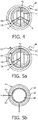
- FIGURE 4 illustrates the needle guide 14 with a rotational encoder 44 that identifies the location of a hole around the guide through which a needle is inserted.
- the encoder identifies a scan plane at a position of ⁇ with respect to the reference plane 42 in which the needle insertion path can be imaged. If a needle is inserted through a hole at the four o'clock position, for instance, the encoder will identify a scan plane at a position of - ⁇ in which the insertion path can be imaged.
- the identified scan plane is communicated to the ultrasound system operating the probe, by either a wired connection or a wireless connection such as a Bluetooth communication link 60.
- Power for the encoder can be provided by either a wired connection or a battery 62.
- the encoder can be constructed in a number of ways.
- One way is to use optical encoding as shown in FIGURE 5a .
- the needle When a needle is inserted through a particular hole, the needle will block the light from the detector for that hole and the detector signal then identifies that particular hole and its corresponding scan plane as one through which a needle is being inserted.
- the ultrasound probe and ultrasound system will then image the identified scan plane and the needle being inserted in that plane.
- the optical detector signal identifies scan plane ⁇ as that of the needle insertion path.
- FIGURE 5b Another encoder implementation which uses a resistive encoder is illustrated in FIGURE 5b .
- the encoder 44 has an outer slip ring with one or more holes or grooves 84 through which a needle can be inserted.
- the outer slip ring 58 can be rotated around an inner ring 56 which has a resistive path 48 around the ring.
- the outer slip ring has a sliding contact 82 in a known relationship to the position of the hole or groove 84 of the slip ring 58 which is in electrical contact with the resistive path 48.
- the sliding contact and resistive path thereby operate as a potentiometer such that an electrical measurement between "+" and "-" terminals electrically connected to the sliding contact 82 and an end of the resistive path will identify the position of the hole or groove around the ring-like structure.
- This position information is reported to the ultrasound system to identify the plane of the needle insertion path to be scanned by the probe and ultrasound system.
- Multiple holes or grooves can be individually identified by connecting an additional resistance in series with a respective terminal so that the range of resistance values reported for one hole does not overlap the range of resistance values for the others.
- FIGURE 6 is an illustration of the relationships between a 3D imaging probe 12, the volume 100 which may be scanned by the probe, and a selected scan plane 102 in which the image field 104 of the probe is positioned.
- a needle 110 is inserted through a hole or groove in the needle guide 14
- the needle is constrained to a path which comes into view beneath the acoustic window of the probe. Since the probe is a 3D imaging probe, it is capable of scanning numerous plane orientations in the volume 100.
- the rotational encoder of the needle guide 14 identifies the particular hole through which the needle is being inserted, which corresponds to a particular scan plane orientation 102 that can be imaged by the 3D imaging probe.
- the probe 12 then images the identified scan plane orientation as illustrated by the sector scan area 104 in plane 102.
- the clinician can then follow the progress of the needle 110 as it is inserted along an insertion path in the sector scan area 104 until the tip 112 of the needle accesses the target anatomy.
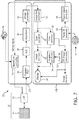
- FIGURE 7 illustrates an ultrasound probe, needle guide, and ultrasound system constructed in accordance with the principles of the present invention.
- the ultrasound system 10 is configured by two subsystems, a front end acquisition subsystem 10A and a display subsystem 10B.
- a 3D ultrasound probe 12 is coupled to the acquisition subsystem which includes a two-dimensional matrix array transducer 70 and a micro-beamformer 72.
- the micro-beamformer contains circuitry which control the signals applied to groups of elements ("patches") of the array transducer 70 and does some processing of the echo signals received by elements of each group.
- Micro-beamforming in the probe advantageously reduces the number of conductors in the cable between the probe and the ultrasound system and is described in US Pat. 5,997,479 (Savord et al. ) and in US Pat. 6,436,048 (Pesque ), and provides electronic steering of beams on transmit and receive for high frame rate real-time (live) 2D or 3D imaging.
- the probe 12 is coupled to the acquisition subsystem 10A of the ultrasound system.
- the acquisition subsystem includes a beamform controller 74 which is responsive to a user control 36 and, for the present invention, a gating signal, which provide control signals to the microbeamformer 72, instructing the probe as to the timing, frequency, direction and focusing of transmit and receive beams and the plane or planes to be scanned by those beams.
- the beamform controller also controls the system beamforming of echo signals received by the acquisition subsystem by its control of analog-to-digital (A/D) converters 18 and a beamformer 20.
- A/D analog-to-digital
- Partially beamformed echo signals received from the probe are amplified by preamplifier and TGC (time gain control) circuitry 16 in the acquisition subsystem, then digitized by the A/D converters 18.
- the digitized echo signals are then formed into fully steered and focused beams by a main system beamformer 20.
- the echo signals are then processed by an image processor 22 which performs digital filtering, B mode and M mode detection, and Doppler processing, and can also perform other signal processing such as harmonic separation, speckle reduction, and other desired image signal processing.
- the echo signals produced by the acquisition subsystem 10A are coupled to the display subsystem 10B, which processes the echo signals for display in the desired image format.
- the echo signals are processed by an image line processor 24, which is capable of sampling the echo signals, splicing segments of beams into complete line signals, and averaging line signals for signal-to-noise improvement or flow persistence.
- the image lines for a 2D image are scan converted into the desired image format by a scan converter 26 which performs R-theta conversion as is known in the art.
- the scan converter can thus format rectilinear or sector image formats.
- the image is then stored in an image memory 28 from which it can be displayed on a display 38.
- the image in memory is also overlaid with graphics to be displayed with the image, which are generated by a graphics generator 34 which is responsive to the user control 36 so that the graphics produced are associated with the images of the display.
- graphics generator 34 which is responsive to the user control 36 so that the graphics produced are associated with the images of the display.
- Individual images or image sequences can be stored in a cine memory 30 during capture of image loops or sequences.
- the display subsystem 10B also includes a 3D image rendering processor 32 which receives image lines from the image line processor 24 for the rendering of real-time three dimensional images.
- the 3D images can be displayed as live (real time) 3D images on the display 38 or coupled to the image memory 28 for storage of the 3D data sets for later review and diagnosis.
- the scan plane identification signal produced by the needle guide 14, which identifies the scan plane in which a needle inserted through the needle guide will pass and can be imaged is coupled to a plane ID processor 52.
- the plane identification signal produced by the plane ID processor is coupled to a trigger signal generator 54 which produces a gating signal that commands the beamformer controller 74 to control the scanning of a desired scan plane, one in which a needle insertion path is located.
- the beamformer controller 74 controls the microbeamformer 72 to scan the desired scan plane and produce echo signals from the scanning of the desired plane which are partially beamformed by the microbeamformer and coupled to the system beamformer 20 for completion of beamformation of scanline in the desired plane.
- the scanlines of the plane are processed by the image line processor 24 and scan converted into a two dimensional image of the identified plane which is displayed on the display 38.
- the identified scan plane can be imaged as a single thin plane within the elevational resolution of the probe and system, but can also be imaged as a thick slice image of a plane thickness greater than that of a single thin plane as described in US patent publication no. US2010/0168580A1 (Thiele et al. )
- the use of thick slice imaging enables the needle to be continually visualized in the image even if its path of insertion varies from a perfectly straight line, so long as the path remains within the thickness of the thick slice image.
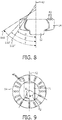
- FIGURES 8 and 9 illustrate another needle guide of the present invention through which needles 110 can be inserted at different inclination angles ⁇ , ⁇ , and ⁇ .
- the cross sectional view of FIGURE 8 shows three needles 110, 110', and 110" inserted through different holes 40 of the needle guide which guide the needles along insertion paths inclined at angles ⁇ , ⁇ , and ⁇ , respectively.
- Each set of three holes at a particular rotational position around the guide will direct the needles along an insertion path in the same scan plane, two of which, ⁇ 1 and ⁇ 2 , are shown in FIGURE 9 in relation to the central reference plane 42.
- the needle guide 14 of FIGURES 8 and 9 enable a clinician to access target anatomy at different depths below the probe while identifying the scan plane of each insertion path.
- FIGURES 4 and 9 illustrate, multiple needles can be inserted at the same time in different identified scan planes ⁇ 1 and ⁇ 2 or + ⁇ and - ⁇ , for example.
- the guide will report the identity of the two different scan plane orientations to the plane ID processor, which will cause the ultrasound system 10 to alternately scan the different planes.
- Two different instruments may be used for microwave ablation of target anatomy, for instance, in which case the clinician will want to visually guide both ablation needles to the target so that their tips are in contact with the anatomy to be ablated.
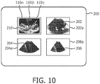
- FIGURE 10 illustrates an ultrasound display which shows four different images of an invasive procedure using a needle guide of the present invention.
- three different needles, 110 ⁇ , 110 ⁇ , and 110 ⁇ are being used and imaged at the same time.
- Needle 110 ⁇ is shown in ultrasound image 202 of the insertion path scan plane of needle 110 ⁇ and the border 202a of this image is colored a unique color such as blue to distinguish the image of needle 110 ⁇ .
- Identifying and coloring a needle in an ultrasound image can be performed by a segmentation technique that specifically identifies the needle in an image from its surrounding tissue as described in US patent pub. no. 2004/0002653 (Greppi et al. ) and in the paper " Enhancement of Needle Visibility in Ultrasound-guided Percutaneous Procedures" by S.
- needles 110 ⁇ and 110 ⁇ are shown in respective 2D images 204 and 206 of their insertion paths and are outlined in distinctive colors 204a and 206a such as red and yellow.
- Image 201 is a full 3D volumetric image of the region of the procedure which shows the target anatomy being accessed by all three needles. In the 3D image each needle is colored with its distinctive color, blue, red, or yellow, so that the clinician can easily relate each needle in the 3D image to its own 2D insertion plane image.
- Each 2D image plane and the full 3D volume are scanned in a time interleaved manner, with the individual insertion planes being scanned at a greater repetition rate (and hence real time frame rate of display) than the 3D image.
- the individual 2D images can be frozen on the screen so that the full acquisition time is devoted to 3D imaging and the procedure at the target anatomy can continue to be imaged in live 3D.
- An implementation of the needle guide and ultrasound system of the present invention can be assisted by other guides to help the clinician plan and carry out a needle insertion procedure, such as guiding the clinician in needle insertion to avoid hard tissues and critical anatomy as described in US patent application no. 61/587,784, filed January 18, 2012 and entitled "ULTRASONIC GUIDANCE OF A NEEDLE PATH DURING BIOPSY" (Kudavelly et al.) Avoidance of hard tissue in the insertion path can help prevent deflection and bending of a needle during insertion. This guidance assistance can be used to plan the insertion path prior to the procedure or to provide guidance as a needle is being inserted.
Landscapes
- Health & Medical Sciences (AREA)
- Life Sciences & Earth Sciences (AREA)
- Surgery (AREA)
- Engineering & Computer Science (AREA)
- Medical Informatics (AREA)
- Molecular Biology (AREA)
- Veterinary Medicine (AREA)
- Nuclear Medicine, Radiotherapy & Molecular Imaging (AREA)
- Biomedical Technology (AREA)
- Heart & Thoracic Surgery (AREA)
- Public Health (AREA)
- Pathology (AREA)
- General Health & Medical Sciences (AREA)
- Animal Behavior & Ethology (AREA)
- Biophysics (AREA)
- Physics & Mathematics (AREA)
- Radiology & Medical Imaging (AREA)
- Computer Networks & Wireless Communication (AREA)
- Computer Vision & Pattern Recognition (AREA)
- Ultra Sonic Daignosis Equipment (AREA)
Applications Claiming Priority (2)
| Application Number | Priority Date | Filing Date | Title |
|---|---|---|---|
| US201261665476P | 2012-06-28 | 2012-06-28 | |
| PCT/IB2013/055319 WO2014002066A2 (en) | 2012-06-28 | 2013-06-28 | Ultrasonically guided biopsies in three dimensions |
Publications (2)
| Publication Number | Publication Date |
|---|---|
| EP2866672A2 EP2866672A2 (en) | 2015-05-06 |
| EP2866672B1 true EP2866672B1 (en) | 2017-02-15 |
Family
ID=49223800
Family Applications (1)
| Application Number | Title | Priority Date | Filing Date |
|---|---|---|---|
| EP13765454.7A Active EP2866672B1 (en) | 2012-06-28 | 2013-06-28 | Ultrasonically guided biopsies in three dimensions |
Country Status (7)
| Country | Link |
|---|---|
| US (1) | US11006923B2 (zh) |
| EP (1) | EP2866672B1 (zh) |
| JP (1) | JP6050487B2 (zh) |
| CN (1) | CN104411251B (zh) |
| BR (1) | BR112014031994B1 (zh) |
| RU (1) | RU2629237C2 (zh) |
| WO (1) | WO2014002066A2 (zh) |
Families Citing this family (10)
| Publication number | Priority date | Publication date | Assignee | Title |
|---|---|---|---|---|
| JP5830576B1 (ja) * | 2014-06-04 | 2015-12-09 | 日立アロカメディカル株式会社 | 医療システム |
| US10238363B2 (en) * | 2014-08-21 | 2019-03-26 | Richard D. Striano | Needle guide for ultrasound transducer |
| WO2016153088A1 (ko) * | 2015-03-23 | 2016-09-29 | 알피니언메디칼시스템 주식회사 | 초음파 프로브용 니들 브래킷, 이를 포함하는 초음파 진단 시스템, 및 니들 삽입 방법 |
| JP7076369B2 (ja) | 2015-12-31 | 2022-05-27 | コーニンクレッカ フィリップス エヌ ヴェ | 介入音響撮像のためのシステム及び方法 |
| US11266374B2 (en) * | 2015-12-31 | 2022-03-08 | Koninklijke Philips N.V. | Device for interventional acoustic imaging |
| JP6668817B2 (ja) * | 2016-02-26 | 2020-03-18 | コニカミノルタ株式会社 | 超音波診断装置、及び制御プログラム |
| ES1195261Y (es) * | 2017-10-06 | 2018-01-17 | Servicio Andaluz De Salud | Dispositivo de guiado para puncion ecoguiada |
| US11395676B2 (en) | 2018-10-22 | 2022-07-26 | Joseph Choate Burkett | Vacuum-assisted insertion device |
| WO2021049148A1 (ja) | 2019-09-13 | 2021-03-18 | 富士フイルム株式会社 | 超音波システムおよび超音波システムの制御方法 |
| WO2022133084A1 (en) * | 2020-12-17 | 2022-06-23 | The Trustees Of Indiana University | Needle guide for ultrasound-guided biopsy |
Family Cites Families (38)
| Publication number | Priority date | Publication date | Assignee | Title |
|---|---|---|---|---|
| CN86205838U (zh) * | 1986-08-11 | 1987-08-12 | 中南橡胶厂职工医院 | 超声波探头附加器 |
| US5255682A (en) | 1990-11-14 | 1993-10-26 | Advanced Technology Laboratories, Inc. | Ultrasonic diagnostic imaging systems with scanhead indicators |
| US5758650A (en) * | 1996-09-30 | 1998-06-02 | Siemens Medical Systems, Inc. | Universal needle guide for ultrasonic transducers |
| US5997479A (en) | 1998-05-28 | 1999-12-07 | Hewlett-Packard Company | Phased array acoustic systems with intra-group processors |
| US6203499B1 (en) | 1998-10-05 | 2001-03-20 | Atl Ultrasound Inc. | Multiple angle needle guide |
| JP4443672B2 (ja) * | 1998-10-14 | 2010-03-31 | 株式会社東芝 | 超音波診断装置 |
| IL126742A0 (en) * | 1998-10-26 | 1999-08-17 | Ultraguide Ltd | Needle and sensor adapters for medical systems |
| US6468216B1 (en) | 2000-08-24 | 2002-10-22 | Kininklijke Philips Electronics N.V. | Ultrasonic diagnostic imaging of the coronary arteries |
| JP3662827B2 (ja) * | 2000-10-02 | 2005-06-22 | アロカ株式会社 | 超音波探触子及び超音波診断装置 |
| US6951542B2 (en) | 2002-06-26 | 2005-10-04 | Esaote S.P.A. | Method and apparatus for ultrasound imaging of a biopsy needle or the like during an ultrasound imaging examination |
| US20040034297A1 (en) | 2002-08-13 | 2004-02-19 | General Electric Company | Medical device positioning system and method |
| JP4280098B2 (ja) * | 2003-03-31 | 2009-06-17 | 株式会社東芝 | 超音波診断装置及び穿刺治療支援プログラム |
| JP2004305535A (ja) * | 2003-04-09 | 2004-11-04 | Ge Medical Systems Global Technology Co Llc | 超音波診断装置 |
| US8123691B2 (en) | 2003-08-19 | 2012-02-28 | Kabushiki Kaisha Toshiba | Ultrasonic diagnostic apparatus for fixedly displaying a puncture probe during 2D imaging |
| JP4828802B2 (ja) * | 2004-05-12 | 2011-11-30 | 株式会社東芝 | 穿刺治療のための超音波診断装置 |
| US20060129046A1 (en) | 2004-12-03 | 2006-06-15 | Sheathing Technologies, Inc. | Methods and devices for coupling a needle to an ultrasound device and guiding advancement of the needle |
| US7497863B2 (en) * | 2004-12-04 | 2009-03-03 | Medtronic, Inc. | Instrument guiding stage apparatus and method for using same |
| JP4634859B2 (ja) * | 2005-05-20 | 2011-02-16 | 株式会社日立メディコ | 治療装置 |
| US9357977B2 (en) | 2006-01-12 | 2016-06-07 | Gynesonics, Inc. | Interventional deployment and imaging system |
| WO2007110076A1 (en) | 2006-03-24 | 2007-10-04 | B-K Medical Aps | Biopsy system |
| JP2007300998A (ja) * | 2006-05-09 | 2007-11-22 | Ge Medical Systems Global Technology Co Llc | 超音波穿刺アタッチメント |
| JP2008148914A (ja) * | 2006-12-18 | 2008-07-03 | Ge Medical Systems Global Technology Co Llc | 3d/4dプローブ用穿刺ガイド装置および超音波診断装置 |
| US20080200798A1 (en) * | 2007-02-19 | 2008-08-21 | Radi Medical Systems Ab | Medical guide for guiding a medical instrument |
| WO2008126015A1 (en) | 2007-04-13 | 2008-10-23 | Koninklijke Philips Electronics, N.V. | High speed ultrasonic thick slice imaging |
| JP2009005802A (ja) * | 2007-06-27 | 2009-01-15 | Ge Medical Systems Global Technology Co Llc | 超音波撮像装置 |
| JP5142675B2 (ja) * | 2007-11-13 | 2013-02-13 | 株式会社東芝 | 超音波診断装置及び超音波診断装置制御プログラム |
| BRPI0819439A8 (pt) * | 2007-11-16 | 2015-11-10 | Koninklijke Philips Electronics Nv | Método e sistema para navegação intervencional usando formação de imagem por ultrassom realçada por contraste em 3d |
| JP2009153831A (ja) * | 2007-12-27 | 2009-07-16 | Ge Medical Systems Global Technology Co Llc | 穿刺ガイドの取付構造、超音波プローブ及び超音波診断装置 |
| US20100063401A1 (en) | 2008-09-09 | 2010-03-11 | Olympus Medical Systems Corp. | Ultrasound endoscope system and ultrasound observation method |
| JP2010068923A (ja) * | 2008-09-17 | 2010-04-02 | Fujifilm Corp | 超音波診断装置 |
| JP5495593B2 (ja) | 2009-03-23 | 2014-05-21 | 株式会社東芝 | 超音波診断装置及び穿刺支援用制御プログラム |
| WO2010125505A1 (en) * | 2009-04-28 | 2010-11-04 | Koninklijke Philips Electronics N.V. | Biopsy guide system with an ultrasound transducer and method of using same |
| US9895135B2 (en) * | 2009-05-20 | 2018-02-20 | Analogic Canada Corporation | Freehand ultrasound imaging systems and methods providing position quality feedback |
| US8449466B2 (en) * | 2009-05-28 | 2013-05-28 | Edwards Lifesciences Corporation | System and method for locating medical devices in vivo using ultrasound Doppler mode |
| CN201701301U (zh) * | 2010-04-08 | 2011-01-12 | 王俊彦 | 超声探头穿刺支架 |
| US8527033B1 (en) * | 2010-07-01 | 2013-09-03 | Sonosite, Inc. | Systems and methods for assisting with internal positioning of instruments |
| CN202015250U (zh) * | 2011-03-10 | 2011-10-26 | 苏州中加医疗科技有限公司 | 一种用于穿刺定位的双平面探头 |
| WO2013108198A1 (en) | 2012-01-18 | 2013-07-25 | Koninklijke Philips N.V. | Ultrasonic guidance of a needle path during biopsy |
-
2013
- 2013-06-28 US US14/409,542 patent/US11006923B2/en active Active
- 2013-06-28 WO PCT/IB2013/055319 patent/WO2014002066A2/en active Application Filing
- 2013-06-28 RU RU2015102573A patent/RU2629237C2/ru active
- 2013-06-28 EP EP13765454.7A patent/EP2866672B1/en active Active
- 2013-06-28 BR BR112014031994-4A patent/BR112014031994B1/pt active IP Right Grant
- 2013-06-28 CN CN201380034284.XA patent/CN104411251B/zh active Active
- 2013-06-28 JP JP2015519459A patent/JP6050487B2/ja active Active
Also Published As
| Publication number | Publication date |
|---|---|
| EP2866672A2 (en) | 2015-05-06 |
| BR112014031994B1 (pt) | 2021-12-28 |
| WO2014002066A3 (en) | 2014-04-24 |
| JP6050487B2 (ja) | 2016-12-21 |
| WO2014002066A2 (en) | 2014-01-03 |
| BR112014031994A2 (pt) | 2017-06-27 |
| CN104411251B (zh) | 2017-08-25 |
| CN104411251A (zh) | 2015-03-11 |
| JP2015521885A (ja) | 2015-08-03 |
| US11006923B2 (en) | 2021-05-18 |
| US20150320439A1 (en) | 2015-11-12 |
| RU2629237C2 (ru) | 2017-08-28 |
| RU2015102573A (ru) | 2016-08-20 |
Similar Documents
| Publication | Publication Date | Title |
|---|---|---|
| EP2866671B1 (en) | Ultrasonic guidance of multiple invasive devices in three dimensions | |
| EP2866672B1 (en) | Ultrasonically guided biopsies in three dimensions | |
| US9597054B2 (en) | Ultrasonic guidance of a needle path during biopsy | |
| US7270634B2 (en) | Guidance of invasive medical devices by high resolution three dimensional ultrasonic imaging | |
| US7796789B2 (en) | Guidance of invasive medical devices by three dimensional ultrasonic imaging | |
| KR101182880B1 (ko) | 영상 지시자를 제공하는 초음파 시스템 및 방법 | |
| EP2036500A1 (en) | Ultrasound diagnostic apparatus | |
| US20060270934A1 (en) | Guidance of invasive medical devices with combined three dimensional ultrasonic imaging system | |
| WO2015092628A1 (en) | Ultrasound imaging systems and methods for tracking locations of an invasive medical device | |
| KR20070061466A (ko) | 천자술용 초음파 프로브 및 초음파 진단 장치 | |
| CN111629671A (zh) | 超声成像设备及控制超声成像设备的方法 | |
| WO2012066470A1 (en) | A method for guiding the insertion of a surgical instrument with three dimensional ultrasonic imaging | |
| EP2640275A1 (en) | Three dimensional ultrasonic guidance of surgical instruments | |
| CN115348839A (zh) | 超声探头、用户控制台、系统和方法 | |
| US20140088430A1 (en) | Ultrasonic image guidance of transcutaneous procedures | |
| JP2009061076A (ja) | 超音波診断装置 |
Legal Events
| Date | Code | Title | Description |
|---|---|---|---|
| PUAI | Public reference made under article 153(3) epc to a published international application that has entered the european phase |
Free format text: ORIGINAL CODE: 0009012 |
|
| 17P | Request for examination filed |
Effective date: 20150128 |
|
| AK | Designated contracting states |
Kind code of ref document: A2 Designated state(s): AL AT BE BG CH CY CZ DE DK EE ES FI FR GB GR HR HU IE IS IT LI LT LU LV MC MK MT NL NO PL PT RO RS SE SI SK SM TR |
|
| AX | Request for extension of the european patent |
Extension state: BA ME |
|
| DAX | Request for extension of the european patent (deleted) | ||
| GRAP | Despatch of communication of intention to grant a patent |
Free format text: ORIGINAL CODE: EPIDOSNIGR1 |
|
| INTG | Intention to grant announced |
Effective date: 20160202 |
|
| GRAS | Grant fee paid |
Free format text: ORIGINAL CODE: EPIDOSNIGR3 |
|
| GRAA | (expected) grant |
Free format text: ORIGINAL CODE: 0009210 |
|
| AK | Designated contracting states |
Kind code of ref document: B1 Designated state(s): AL AT BE BG CH CY CZ DE DK EE ES FI FR GB GR HR HU IE IS IT LI LT LU LV MC MK MT NL NO PL PT RO RS SE SI SK SM TR |
|
| REG | Reference to a national code |
Ref country code: CH Ref legal event code: EP Ref country code: GB Ref legal event code: FG4D |
|
| REG | Reference to a national code |
Ref country code: IE Ref legal event code: FG4D |
|
| REG | Reference to a national code |
Ref country code: AT Ref legal event code: REF Ref document number: 867449 Country of ref document: AT Kind code of ref document: T Effective date: 20170315 |
|
| REG | Reference to a national code |
Ref country code: DE Ref legal event code: R096 Ref document number: 602013017503 Country of ref document: DE |
|
| REG | Reference to a national code |
Ref country code: DE Ref legal event code: R084 Ref document number: 602013017503 Country of ref document: DE |
|
| REG | Reference to a national code |
Ref country code: GB Ref legal event code: 746 Effective date: 20170419 |
|
| REG | Reference to a national code |
Ref country code: NL Ref legal event code: MP Effective date: 20170215 |
|
| REG | Reference to a national code |
Ref country code: LT Ref legal event code: MG4D |
|
| REG | Reference to a national code |
Ref country code: FR Ref legal event code: PLFP Year of fee payment: 5 |
|
| REG | Reference to a national code |
Ref country code: AT Ref legal event code: MK05 Ref document number: 867449 Country of ref document: AT Kind code of ref document: T Effective date: 20170215 |
|
| PG25 | Lapsed in a contracting state [announced via postgrant information from national office to epo] |
Ref country code: NO Free format text: LAPSE BECAUSE OF FAILURE TO SUBMIT A TRANSLATION OF THE DESCRIPTION OR TO PAY THE FEE WITHIN THE PRESCRIBED TIME-LIMIT Effective date: 20170515 Ref country code: FI Free format text: LAPSE BECAUSE OF FAILURE TO SUBMIT A TRANSLATION OF THE DESCRIPTION OR TO PAY THE FEE WITHIN THE PRESCRIBED TIME-LIMIT Effective date: 20170215 Ref country code: GR Free format text: LAPSE BECAUSE OF FAILURE TO SUBMIT A TRANSLATION OF THE DESCRIPTION OR TO PAY THE FEE WITHIN THE PRESCRIBED TIME-LIMIT Effective date: 20170516 Ref country code: LT Free format text: LAPSE BECAUSE OF FAILURE TO SUBMIT A TRANSLATION OF THE DESCRIPTION OR TO PAY THE FEE WITHIN THE PRESCRIBED TIME-LIMIT Effective date: 20170215 Ref country code: HR Free format text: LAPSE BECAUSE OF FAILURE TO SUBMIT A TRANSLATION OF THE DESCRIPTION OR TO PAY THE FEE WITHIN THE PRESCRIBED TIME-LIMIT Effective date: 20170215 |
|
| PG25 | Lapsed in a contracting state [announced via postgrant information from national office to epo] |
Ref country code: SE Free format text: LAPSE BECAUSE OF FAILURE TO SUBMIT A TRANSLATION OF THE DESCRIPTION OR TO PAY THE FEE WITHIN THE PRESCRIBED TIME-LIMIT Effective date: 20170215 Ref country code: BG Free format text: LAPSE BECAUSE OF FAILURE TO SUBMIT A TRANSLATION OF THE DESCRIPTION OR TO PAY THE FEE WITHIN THE PRESCRIBED TIME-LIMIT Effective date: 20170515 Ref country code: PT Free format text: LAPSE BECAUSE OF FAILURE TO SUBMIT A TRANSLATION OF THE DESCRIPTION OR TO PAY THE FEE WITHIN THE PRESCRIBED TIME-LIMIT Effective date: 20170615 Ref country code: NL Free format text: LAPSE BECAUSE OF FAILURE TO SUBMIT A TRANSLATION OF THE DESCRIPTION OR TO PAY THE FEE WITHIN THE PRESCRIBED TIME-LIMIT Effective date: 20170215 Ref country code: LV Free format text: LAPSE BECAUSE OF FAILURE TO SUBMIT A TRANSLATION OF THE DESCRIPTION OR TO PAY THE FEE WITHIN THE PRESCRIBED TIME-LIMIT Effective date: 20170215 Ref country code: AT Free format text: LAPSE BECAUSE OF FAILURE TO SUBMIT A TRANSLATION OF THE DESCRIPTION OR TO PAY THE FEE WITHIN THE PRESCRIBED TIME-LIMIT Effective date: 20170215 Ref country code: ES Free format text: LAPSE BECAUSE OF FAILURE TO SUBMIT A TRANSLATION OF THE DESCRIPTION OR TO PAY THE FEE WITHIN THE PRESCRIBED TIME-LIMIT Effective date: 20170215 Ref country code: RS Free format text: LAPSE BECAUSE OF FAILURE TO SUBMIT A TRANSLATION OF THE DESCRIPTION OR TO PAY THE FEE WITHIN THE PRESCRIBED TIME-LIMIT Effective date: 20170215 |
|
| PG25 | Lapsed in a contracting state [announced via postgrant information from national office to epo] |
Ref country code: EE Free format text: LAPSE BECAUSE OF FAILURE TO SUBMIT A TRANSLATION OF THE DESCRIPTION OR TO PAY THE FEE WITHIN THE PRESCRIBED TIME-LIMIT Effective date: 20170215 Ref country code: SK Free format text: LAPSE BECAUSE OF FAILURE TO SUBMIT A TRANSLATION OF THE DESCRIPTION OR TO PAY THE FEE WITHIN THE PRESCRIBED TIME-LIMIT Effective date: 20170215 Ref country code: CZ Free format text: LAPSE BECAUSE OF FAILURE TO SUBMIT A TRANSLATION OF THE DESCRIPTION OR TO PAY THE FEE WITHIN THE PRESCRIBED TIME-LIMIT Effective date: 20170215 Ref country code: RO Free format text: LAPSE BECAUSE OF FAILURE TO SUBMIT A TRANSLATION OF THE DESCRIPTION OR TO PAY THE FEE WITHIN THE PRESCRIBED TIME-LIMIT Effective date: 20170215 |
|
| REG | Reference to a national code |
Ref country code: DE Ref legal event code: R097 Ref document number: 602013017503 Country of ref document: DE |
|
| PG25 | Lapsed in a contracting state [announced via postgrant information from national office to epo] |
Ref country code: DK Free format text: LAPSE BECAUSE OF FAILURE TO SUBMIT A TRANSLATION OF THE DESCRIPTION OR TO PAY THE FEE WITHIN THE PRESCRIBED TIME-LIMIT Effective date: 20170215 Ref country code: PL Free format text: LAPSE BECAUSE OF FAILURE TO SUBMIT A TRANSLATION OF THE DESCRIPTION OR TO PAY THE FEE WITHIN THE PRESCRIBED TIME-LIMIT Effective date: 20170215 Ref country code: SM Free format text: LAPSE BECAUSE OF FAILURE TO SUBMIT A TRANSLATION OF THE DESCRIPTION OR TO PAY THE FEE WITHIN THE PRESCRIBED TIME-LIMIT Effective date: 20170215 |
|
| PLBE | No opposition filed within time limit |
Free format text: ORIGINAL CODE: 0009261 |
|
| STAA | Information on the status of an ep patent application or granted ep patent |
Free format text: STATUS: NO OPPOSITION FILED WITHIN TIME LIMIT |
|
| 26N | No opposition filed |
Effective date: 20171116 |
|
| PG25 | Lapsed in a contracting state [announced via postgrant information from national office to epo] |
Ref country code: MC Free format text: LAPSE BECAUSE OF FAILURE TO SUBMIT A TRANSLATION OF THE DESCRIPTION OR TO PAY THE FEE WITHIN THE PRESCRIBED TIME-LIMIT Effective date: 20170215 |
|
| REG | Reference to a national code |
Ref country code: CH Ref legal event code: PL |
|
| PG25 | Lapsed in a contracting state [announced via postgrant information from national office to epo] |
Ref country code: SI Free format text: LAPSE BECAUSE OF FAILURE TO SUBMIT A TRANSLATION OF THE DESCRIPTION OR TO PAY THE FEE WITHIN THE PRESCRIBED TIME-LIMIT Effective date: 20170215 |
|
| REG | Reference to a national code |
Ref country code: IE Ref legal event code: MM4A |
|
| PG25 | Lapsed in a contracting state [announced via postgrant information from national office to epo] |
Ref country code: CH Free format text: LAPSE BECAUSE OF NON-PAYMENT OF DUE FEES Effective date: 20170630 Ref country code: IE Free format text: LAPSE BECAUSE OF NON-PAYMENT OF DUE FEES Effective date: 20170628 Ref country code: LI Free format text: LAPSE BECAUSE OF NON-PAYMENT OF DUE FEES Effective date: 20170630 Ref country code: LU Free format text: LAPSE BECAUSE OF NON-PAYMENT OF DUE FEES Effective date: 20170628 |
|
| REG | Reference to a national code |
Ref country code: BE Ref legal event code: MM Effective date: 20170630 |
|
| REG | Reference to a national code |
Ref country code: FR Ref legal event code: PLFP Year of fee payment: 6 |
|
| PG25 | Lapsed in a contracting state [announced via postgrant information from national office to epo] |
Ref country code: BE Free format text: LAPSE BECAUSE OF NON-PAYMENT OF DUE FEES Effective date: 20170630 |
|
| PG25 | Lapsed in a contracting state [announced via postgrant information from national office to epo] |
Ref country code: MT Free format text: LAPSE BECAUSE OF NON-PAYMENT OF DUE FEES Effective date: 20170628 |
|
| PG25 | Lapsed in a contracting state [announced via postgrant information from national office to epo] |
Ref country code: HU Free format text: LAPSE BECAUSE OF FAILURE TO SUBMIT A TRANSLATION OF THE DESCRIPTION OR TO PAY THE FEE WITHIN THE PRESCRIBED TIME-LIMIT; INVALID AB INITIO Effective date: 20130628 |
|
| PG25 | Lapsed in a contracting state [announced via postgrant information from national office to epo] |
Ref country code: CY Free format text: LAPSE BECAUSE OF FAILURE TO SUBMIT A TRANSLATION OF THE DESCRIPTION OR TO PAY THE FEE WITHIN THE PRESCRIBED TIME-LIMIT Effective date: 20170215 |
|
| PG25 | Lapsed in a contracting state [announced via postgrant information from national office to epo] |
Ref country code: MK Free format text: LAPSE BECAUSE OF FAILURE TO SUBMIT A TRANSLATION OF THE DESCRIPTION OR TO PAY THE FEE WITHIN THE PRESCRIBED TIME-LIMIT Effective date: 20170215 |
|
| PG25 | Lapsed in a contracting state [announced via postgrant information from national office to epo] |
Ref country code: TR Free format text: LAPSE BECAUSE OF FAILURE TO SUBMIT A TRANSLATION OF THE DESCRIPTION OR TO PAY THE FEE WITHIN THE PRESCRIBED TIME-LIMIT Effective date: 20170215 |
|
| PG25 | Lapsed in a contracting state [announced via postgrant information from national office to epo] |
Ref country code: AL Free format text: LAPSE BECAUSE OF FAILURE TO SUBMIT A TRANSLATION OF THE DESCRIPTION OR TO PAY THE FEE WITHIN THE PRESCRIBED TIME-LIMIT Effective date: 20170215 Ref country code: IS Free format text: LAPSE BECAUSE OF FAILURE TO SUBMIT A TRANSLATION OF THE DESCRIPTION OR TO PAY THE FEE WITHIN THE PRESCRIBED TIME-LIMIT Effective date: 20170615 |
|
| PGFP | Annual fee paid to national office [announced via postgrant information from national office to epo] |
Ref country code: FR Payment date: 20230622 Year of fee payment: 11 Ref country code: DE Payment date: 20230627 Year of fee payment: 11 |
|
| PGFP | Annual fee paid to national office [announced via postgrant information from national office to epo] |
Ref country code: IT Payment date: 20230620 Year of fee payment: 11 Ref country code: GB Payment date: 20230620 Year of fee payment: 11 |