EP2865091B1 - Verfahren und schaltungsanordnung zum ansteuern eines schrittmotors - Google Patents
Verfahren und schaltungsanordnung zum ansteuern eines schrittmotors Download PDFInfo
- Publication number
- EP2865091B1 EP2865091B1 EP13742151.7A EP13742151A EP2865091B1 EP 2865091 B1 EP2865091 B1 EP 2865091B1 EP 13742151 A EP13742151 A EP 13742151A EP 2865091 B1 EP2865091 B1 EP 2865091B1
- Authority
- EP
- European Patent Office
- Prior art keywords
- segment
- base
- value
- current
- support point
- Prior art date
- Legal status (The legal status is an assumption and is not a legal conclusion. Google has not performed a legal analysis and makes no representation as to the accuracy of the status listed.)
- Active
Links
Images

Classifications
-
- H—ELECTRICITY
- H02—GENERATION; CONVERSION OR DISTRIBUTION OF ELECTRIC POWER
- H02P—CONTROL OR REGULATION OF ELECTRIC MOTORS, ELECTRIC GENERATORS OR DYNAMO-ELECTRIC CONVERTERS; CONTROLLING TRANSFORMERS, REACTORS OR CHOKE COILS
- H02P8/00—Arrangements for controlling dynamo-electric motors rotating step by step
- H02P8/22—Control of step size; Intermediate stepping, e.g. microstepping
-
- H—ELECTRICITY
- H02—GENERATION; CONVERSION OR DISTRIBUTION OF ELECTRIC POWER
- H02P—CONTROL OR REGULATION OF ELECTRIC MOTORS, ELECTRIC GENERATORS OR DYNAMO-ELECTRIC CONVERTERS; CONTROLLING TRANSFORMERS, REACTORS OR CHOKE COILS
- H02P8/00—Arrangements for controlling dynamo-electric motors rotating step by step
- H02P8/12—Control or stabilisation of current
Definitions
- the invention relates to a method and a circuit arrangement for driving a 2-, 3- or multi-phase stepping motor with predetermined current waveforms, in particular for a micro-stepping operation.
- stepper motors In stepping motors, the rotor is incrementally rotated by a small angle through a controlled electromagnetic field generated by static motor coils and incrementally rotating. Stepper motors are therefore used everywhere where an accurate linear or rotary positioning of an object is important. In addition, however, stepper motors are increasingly being used for pure drive purposes, for which conventional DC motors have hitherto been used, for example. There are many different types of stepper motors known, with u. a. is distinguished according to the number of motor coils between 2-, 3- and multi-phase stepper motors.
- stepper motors for example, known chopper methods are used with which from a supplied motor supply voltage for each of the motor coils for each time in this according to a current specification (desired coil current) terme josgende current direction, current level and current waveform by means of PWM current pulses is generated in order to drive the rotor of the motor with the thus induced, rotating magnetic field.
- a current specification desired coil current
- PWM current pulses current level and current waveform by means of PWM current pulses is generated in order to drive the rotor of the motor with the thus induced, rotating magnetic field.
- the so-called microstep operation is preferred in which the currents flowing through the motor coils are not only switched on and off, but also rise and fall in a certain way.
- the accuracy with which the stepper motor handles the microsteps essentially depends on how many different current amplitudes the motor coils are driven and how exactly they can be maintained.
- a sinusoidal or cosinusoidal excitation of the motor coils is generally most expedient, since thus also a very continuous, ie jolt-free rotation and thus a smooth engine operation can be achieved.
- the requirements for the precision of the synchronization of the motor are particularly high.
- the actual realization of these desired optimum current curves can then be e.g. by a Fourier synthesis of various sine or triangle functions or mixtures thereof.
- the resulting current curves are usually steady, but not necessarily monotonically increasing or monotonically decreasing. However, typically the four quadrants of the current curve are also symmetric due to the symmetrical design of the motors so that only a quarter of the current curve needs to be stored.
- a support point of the current curve ie a value of the current curve amplitude
- a memory location having to record a number with an accuracy corresponding to the quantization resolution of the current amplitude values.
- a motor driving circuit in which waveform data for a sinusoidal motor current waveform for half a period of the sinusoid are stored in a memory.
- a polarity inverter circuit for the waveform data essentially a polarity inverter circuit for the waveform data, an address counter with inter alia a flag bit for polarity switching, and a generator for PWM current pulses are provided.
- a setpoint current generation device for stepping motors in which reference points for a setpoint current profile are stored in a memory and intermediate values between two interpolation points are generated in order to save storage space by interpolation.
- the invention has for its object to provide a method and a circuit arrangement for driving a 2-, 3- or multi-phase stepping motor, with the / in a relatively simple manner and at the same time with high accuracy a desired course of the amplitudes of the current curves through the motor coils can be realized, especially if this course deviates from the usual sinusoidal or cosinus form.
- the table containing the data required to produce the desired waveforms has only about a 15 to 20% reduction in complexity compared to the above storage of full amplitude values for each node of the current waveform needs.
- the table can be realized as a flip-flop register in the digital part of a stepper motor driver, and the layout cut by a separate RAM block is minimized.
- the disclosed solution is also advantageous in that the current amplitude values in both directions, i. can be read for a clockwise and counterclockwise rotation of the engine.
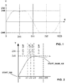
- FIG. 1 shows a typical time course of a predetermined current curve (with current amplitude values Y over the time axis X) over a full period for driving a phase of a stepping motor in microstep operation, when increased demands are placed on the precision of the synchronization of the motor.
- the curve is, as already mentioned, by synthesis of different Sinusoidal and triangular functions or mixtures thereof produced in a known manner so that the requirements placed on the engine or the positioning accuracy are met.
- the graph shows that while such current curves are generally continuous, in the mathematical sense they are not necessarily monotonically increasing or monotonically decreasing.
- the current course in the four quadrants of a period is symmetrical, so that the entire curve must be determined and stored for only one quadrant and the current waveforms in the other quadrants thereof can be determined with simple arithmetic operations by symmetric mirroring.
- the current curve is composed of a total of 1,024 reference points along a full period, the time intervals (ie the distances along the X axis) between two adjacent reference points preferably being equal and each of the reference points 0 through 1023 being one quantized amplitude value Y of the current is assigned in such a way that in the FIG. 1 shown current curve results.
- the current amplitudes can assume a maximum of 256 discrete positive or (due to the symmetry mentioned) a maximum of 256 discrete negative values, whereby generally a predefined current curve profile can be generated with sufficient accuracy.
- step and quantization resolutions can also be implemented.
- the first quadrant of the current waveform along the time axis X is divided into four exemplary segments W0, W1, W2, W3.
- the deviation can also be represented by a multi-bit value (for example by a binary number with two or more digits) in order to allow a more accurate quantification of the deviation.
- a multi-bit value for example by a binary number with two or more digits
- the deviation is represented by the above-mentioned 1-bit value.
- the lowest slope of the current curve profile that is present there is determined at a support point and set as the base or base gradient.
- the desired current waveform is calculated in advance and digitized according to the quantization resolution (resolution of the amplitude values).
- the value 1 is then entered into a table for each interpolation point in which the digitized amplitude value at this interpolation point is higher than the base or base slope by the predetermined fixed number n of quantization stages compared to the amplitude value at the preceding interpolation point.
- the value 0 is entered if this is not the case, i. if the digitized amplitude value at this support point coincides with the amplitude value at the preceding support point plus the base or base slope or is only higher by a number m ⁇ n of quantization steps.
- each segment W0, W1, W2, W3 determines within each segment W0, W1, W2, W3 the respectively existing, highest slope of the current waveform at a support point and set as base or base slope and then enter a value of 1 in the table for each support point, wherein the digitized amplitude value at this support point is lower than the base or base slope by the predetermined fixed number n of quantization steps compared to the amplitude value at the preceding support point.
- the value 0 is entered if this is not the case, i. if the digitized amplitude value at this support point coincides with the amplitude value at the preceding support point plus the base or base slope or is only lower by a number m ⁇ n of quantization steps.
- the length of the segments ie the number of nodes within a segment, in the case of the determination of the lowest slope as the base or Base pitch must be dimensioned so that within a segment, the deviation of the slope of each adjacent support points of the base or base pitch is not greater than the predetermined fixed number n of quantization levels and amount not less than the base or base pitch itself.
- the length of the segments i. the number of interpolation points within a segment, in the case of the determination of the highest gradient as base or base pitch, are dimensioned so that within one segment the deviation of the pitch at respectively adjacent interpolation points from the base or base pitch is not smaller than the predetermined fixed number n of quantization levels and in terms of amount does not become larger than the base or base slope itself.
- the segments are relatively short, while in the areas in which the slope changes only slightly, the segments relative can be long.
- the actual digital value Y of the current amplitude at a node s then results in the case of the determination of the lowest slope as base or base slope of the sum of s times the base or base pitch W (which is, for example, two quantization levels per support point) , plus the number of values 1, this number being to be multiplied by the number n of quantization steps, and possibly added to the nodes 0 to s, respectively.
- the actual digital value Y of the current amplitude at a support point s results from the sum of s times the base or base slope W (which, for example, is two quantization levels per support point), minus the number of values 1, wherein this number is to be multiplied by the number n of the quantization steps, and which have possibly been subtracted from the interpolation points 0 to s, respectively.
- the first segment W0 extends between the support point 0 at the beginning of the (first) quadrant and a support point X1, the second segment W1 between the support point X1 and a support point X2, the third segment W2 between the support point X2 and a support point X3 and the fourth Segment W3 between the support point X3 and the support point 255 at the end of the (first) quadrant.
- Example is according to FIG. 2 the base or base pitch W selected in each case as the lowest pitch W in the first segment W0: +2, in the second segment W1: +1, in the third segment W2: 0 and in the fourth segment W3: -1.
- initialization values are preferably additionally stored in the table for specific support points.
- such initialization values may be at the beginning of each quadrant, wherein in the case of a sine wave, the current amplitude of the first node 0 always receives the value 0.
- an initialization for the 90 ° value can take place at the first interpolation point 0.
- the current waveform over the entire period is symmetrical, so that the processes described for the first quadrant in the second to fourth quadrant repeat symmetrically and can be determined by simple arithmetic operations from the values stored in the table for the first quadrant.
- FIG. 3 shows an exemplary simplified block diagram of a circuit arrangement for generating the values Y of the current amplitudes at each support point, ie for each microstep of a stepping motor, wherein the present at the output of the circuit current amplitude values Y are fed to a known current controller or a known motor driver circuit.
- the circuit can be adapted accordingly.
- FIG. 1 the progression of the current amplitude through the motor coils is determined in advance as a function of certain motor parameters as well as the demands placed on the synchronization of the motor and possibly other requirements.
- one quadrant of the current amplitude curve is then segmented according to the above explanations, wherein the number and the length of the individual segments as well as the base or base slope within each segment are preferably calculated with a corresponding computer program according to the above criteria.
- the essential components of the circuit arrangement are a table memory 10, preferably in the form of a 256 * 1 bit RAM in the case of 256 nodes or microsteps per quadrant of the current waveform, a micro-step counter 13, a start-up memory 16, a microstep register 12, a segment comparator 18, a first multiplexer 11 for the basic pitches W0, ... W3, a second multiplexer 19 for starting values, a first and a second adder A1, A2, a multiplier 17 and a first and a second comparator 14, 15.
- the circuit arrangement Via an input Cl, the circuit arrangement is supplied with a step-clock, with which in each case from a microstep (or a support point of the current waveform) to a next microstep (or a next interpolation point) is further switched.
- the step clock Cl supplied via the input is supplied to the micro-step counter 13, which cycles these clocks according to the number of nodes in each Current curve period counts, so that the respective count each one of the nodes of the current curve period designates.
- the current count is transmitted to the table memory 10 with each clock. Then, from the table stored in the table memory 10, that 1-bit value (0 or 1) which is assigned to the interpolation point of the current curve period corresponding to the counter reading by the table is read out.
- the counter reading is also supplied to the segment comparator 18, with which it is determined within which segment W0, Wn the respective reference point represented by the counter reading is located. For this purpose, the count is compared with those stored nodes X1, ... Xn, each representing a transition or a boundary between two segments W0, ... Wn. With the output signal of the segment comparator 18, the first multiplexer 11 is driven so that applied to the output of the determined for the determined segment base or base pitch. With the first adder A1, this base or base slope is then added to the 1-bit value read from the table memory 10 and the sum is applied to the multiplier 17.
- the counter reading is further supplied to a first comparator 14, with which it is determined whether the interpolation point represented by the counter reading is located in a positive or a negative quadrant of the current waveform.
- the multiplier 17 is controlled in such a way that the sum applied to its input is multiplied by the factor 1 when the interpolation point is in a positive quadrant and multiplied by the factor -1 when the support point is located in a negative quadrant of the current waveform.
- the thus-signed sum of base slope and 1-bit value is then supplied to the second adder A2, with which this sum is added to the output of the micro-step register 12.
- the output signal of the second adder A2 is then fed back to the input of the microstep register 12 via the second multiplexer 19 for starting values, in order to generate by accumulation or addition the current amplitude value Y for the interpolation point of the current waveform represented by the supplied step clock signal.
- the second multiplexer 19 for start values serves for the initialization explained above. If at the beginning of a period of the current waveform (again) the first step clock is applied to the circuit input and thus the state of the micro-step counter 13 (again) assumes the value 1, the second multiplexer 19 is controlled by the second comparator 15 so that instead of Output of the second adder A2, a stored in the memory 16 starting value via the second multiplexer 19 is applied to the input of the micro-step register 12.
- the circuit arrangement shown is preferably provided with a second input which is connected to the micro-step counter 13 and by means of which it can be switched by means of a supplied switching signal between a forward and a backward counting direction to a direction of rotation of the motor in both directions enable.
- the described circuit arrangement is preferably realized as part of an integrated drive circuit for 2, 3 or more phase stepper motors.
Landscapes
- Engineering & Computer Science (AREA)
- Power Engineering (AREA)
- Control Of Stepping Motors (AREA)
Description
- Die Erfindung betrifft ein Verfahren und eine Schaltungsanordnung zum Ansteuern eines 2-, 3-oder Mehrphasen-Schrittmotors mit vorgegebenen Stromkurvenverläufen, insbesondere für einen Mikroschrittbetrieb.
- Bei Schrittmotoren wird der Rotor durch ein gesteuertes, mit statischen Motorspulen erzeugtes und schrittweise rotierendes elektromagnetisches Feld schrittweise um jeweils einen kleinen Winkel gedreht. Schrittmotoren finden deshalb überall dort Anwendung, wo es auf eine genaue lineare oder Dreh-Positionierung eines Objektes ankommt. Darüber hinaus werden Schrittmotoren aber in zunehmendem Maße auch für reine Antriebszwecke verwendet, für die bisher zum Beispiel übliche Gleichstrommotoren eingesetzt wurden. Es sind zahlreiche verschiedene Bauformen von Schrittmotoren bekannt, wobei u. a. entsprechend der Anzahl der Motorspulen zwischen 2-, 3- und Mehrphasen-Schrittmotoren unterschieden wird.
- Zum elektrischen Ansteuern von Schrittmotoren dienen zum Beispiel bekannte Chopper-Verfahren, mit denen aus einer zugeführten Motor-Versorgungsspannung für jede der Motorspulen die für jeden Zeitpunkt in diese entsprechend einer Stromvorgabe (Spulen-Sollstrom) jeweils einzuprägende Stromrichtung, Stromhöhe und Stromform mittels PWM-Strompulsen erzeugt wird, um mit dem dadurch induzierten, rotierenden Magnetfeld den Rotor des Motors anzutreiben.
- Dabei besteht häufig der Wunsch, den Motor mit möglichst kleinen Schrittwinkeln drehen zu können, um eine möglichst hohe Auflösung bzw. Genauigkeit der Positionierung und einen gleichmäßigeren Drehmomentverlauf zu erzielen. Aus diesem Grunde wird anstelle des bekannten Vollschritt- und Halbschritt-Betriebes der so genannte Mikroschrittbetrieb bevorzugt, bei dem die durch die Motorspulen fließenden Ströme nicht nur ein- und ausgeschaltet werden, sondern in bestimmter Weise ansteigen und abfallen. Die Genauigkeit, mit der der Schrittmotor die Mikroschritte ausführt, hängt dabei im Wesentlichen davon ab, mit wie viel verschiedenen Stromamplituden die Motorspulen angesteuert werden und wie genau diese eingehalten werden können. Dabei ist eine sinusförmige bzw. cosinusförmige Erregung der Motorspulen im Allgemeinen am zweckmäßigsten, da damit auch ein sehr kontinuierliches, d.h. ruckfreies Drehen und somit ein ruhiger Motorlauf erzielt werden kann.
- Bei bestimmten Anwendungen sind die Anforderungen an die Präzision des Gleichlaufes des Motors jedoch besonders hoch. Um diese Anforderungen erfüllen zu können, ist es erforderlich, den Kurvenverlauf des Stroms durch die Motorspulen für die Mikroschritterzeugung an die Motorgeometrie (d.h. an einen bestimmten Motortyp und dessen Parameter, gegebenenfalls auch an einen individuellen Motor) anzupassen. Die tatsächliche Realisierung dieser gewünschten optimalen Stromkurven kann dann z.B. durch eine Fourier-Synthese verschiedener Sinus- oder Dreiecks-Funktionen oder Mischungen daraus erfolgen.
- Die auf diese Weise entstandenen Stromkurven sind üblicherweise stetig, jedoch nicht unbedingt monoton steigend oder monoton fallend. Allerdings sind typischerweise die vier Quadranten der Stromkurve aufgrund des symmetrischen Aufbaus der Motoren ebenfalls symmetrisch, so dass nur ein Viertel der Stromkurve gespeichert werden braucht.
- Dennoch ist die Speicherung einer solchen Kurve insbesondere innerhalb eines monolithischen Schrittmotor-Ansteuer-ICs sehr aufwändig. Für jeden Mikroschritt des Motors ist eine Stützstelle der Stromkurve, d.h. ein Wert der Stromkurvenamplitude, abzuspeichern, wobei ein solcher Speicherplatz eine Zahl mit einer Genauigkeit entsprechend der Quantisierungsauflösung der Stromamplitudenwerte aufnehmen muss. Dies bedeutet bei z.B. 256 Mikroschritten in jedem Quadrant mit einer Auflösung von 256 diskreten Stromwerten für jeden Mikroschritt eine Zahl von 256∗8 Bit. Eine im Vergleich zur Komplexität des digitalen Kerns eines üblichen SchrittmotorTreibers so hohe Anzahl von Speicherstellen für die Stromkurve lässt eine solche Realisierung bereits ab einer Auflösung von wenigen zehn Mikroschritten als zu dominant für die Komplexität des Baustein und damit als nicht marktgerecht erscheinen.
- Eine alternative Realisierung eines Stromkurven-Speichers als RAM-Block ist erfahrungsgemäß nur sehr aufwändig in ein vorhandenes Chip-Design einzubauen und ungünstig in ein Chip-Layout zu integrieren, da ein RAM-Block als separater Layout-Block erscheint. Weiterhin erfordert ein RAM-Block in jedem Fall, dass ein Anwender die Mikroschritt-Tabelle beschreibt. Eine solche Tabelle kann jedoch nicht ohne Aufwand über Reset-Werte beispielsweise mit einer Sinusfunktion vorbesetzt werden. Dies wäre aber interessant, um die Universalität und Einfachheit des Bausteins auch für Anwendungen, in denen die Kurve nicht programmiert werden muss, aufrecht erhalten zu können.
- Aus der
US 2010/0141199 A1 ist eine Motor-Treiberschaltung bekannt, bei der Wellenform-Daten für eine Sinusförmige Motorstromkurve für eine halbe Periode der Sinuskurve in einem Speicher gespeichert werden. Zur Erzeugung einer vollständigen Stromkurve ist im Wesentlichen eine Polaritäts-Inverterschaltung für die Wellenform-Daten, ein Adresszähler mit u.a. einem Flag-bit zur Polaritätsumschaltung, und ein Generator für PWM-Strompulse vorgesehen. - Aus der
DE 198 42 698 A1 ist eine Sollstromerzeugungsvorrichtung für Schrittmotoren bekannt, bei der Stützstellen für einen Sollstromverlauf in einem Speicher gespeichert und Zwischenwerte zwischen zwei Stützstellen zur Einsparung von Speicherplatz durch eine Interpolation erzeugt werden. - Der Erfindung liegt die Aufgabe zugrunde, ein Verfahren und eine Schaltungsanordnung zum Ansteuern eines 2-, 3- oder Mehrphasen-Schrittmotors zu schaffen, mit dem/der in relativ einfacher Weise und gleichzeitig mit hoher Genauigkeit ein gewünschter Verlauf der Amplituden der Stromkurven durch die Motorspulen realisiert werden kann, insbesondere wenn dieser Verlauf von der üblichen sinus- bzw. cosinus-Form abweicht.
- Gelöst wird diese Aufgabe mit einem Verfahren gemäß Anspruch 1 und einer Schaltungsanordnung gemäß Anspruch 6.
- Ein Vorteil dieser Lösung besteht darin, dass die Tabelle, die die zur Erzeugung der gewünschten Stromkurvenverläufe erforderlichen Daten enthält, nur eine auf etwa 15 bis 20% reduzierte Komplexität im Vergleich zu der oben genannten Speicherung der vollständigen Amplitudenwerte für jede Stützstelle des Stromverlaufes aufzuweisen braucht. Dadurch kann die Tabelle als Flip-Flop-Register im Digitalteil eines Schrittmotortreibers realisiert werden, und der Layout-Verschnitt durch einen separaten RAM-Block wird minimiert.
- Ferner können mit dem offenbarten Verfahren und der offenbarten Ansteuerschaltung prinzipiell sämtliche stetigen Stromkurven-Verläufe, die für einen Schrittmotor relevant sein können, realisiert werden.
- Schließlich ist die offenbarte Lösung auch insofern vorteilhaft, als die Stromamplitudenwerte in beiden Richtungen, d.h. für einen Rechts- und einen Linkslauf des Motors ausgelesen werden können.
- Die Unteransprüche haben vorteilhafte Weiterbildungen der Erfindung zum Inhalt.
- Weitere Einzelheiten, Merkmale und Vorteile der Offenbarung ergeben sich aus der folgenden Beschreibung von bevorzugten Ausführungsformen anhand der Zeichnung. Es zeigt:
- Fig. 1
- einen typischen vorgegebenen Verlauf einer Stromkurve durch die Motorspulen eines Schrittmotors;
- Fig. 2
- eine vergrößerte Darstellung des ersten Quadranten des Stromkurvenverlaufes gemäß
Figur 1 ; und - Fig. 3
- ein beispielhaftes Blockschaltbild als Teil einer integrierten Schaltungsanordnung gemäß der Offenbarung.
-
Figur 1 zeigt einen typischen zeitlichen Verlauf einer vorgegebenen Stromkurve (mit Stromamplitudenwerten Y über der Zeitachse X) über eine volle Periode zur Ansteuerung einer Phase eines Schrittmotors im Mikroschrittbetrieb, wenn erhöhte Anforderungen an die Präzision des Gleichlaufes des Motors gestellt werden. Die Kurve wird, wie eingangs bereits erwähnt wurde, durch Synthese verschiedener Sinus- und Dreiecksfunktionen oder Mischungen daraus in bekannter Weise so erzeugt, dass die an den Motorlauf oder die Positioniergenauigkeit gestellten Anforderungen erfüllt werden. - Die Kurve zeigt, dass solche Stromverläufe zwar im Allgemeinen stetig, im mathematischen Sinne aber nicht unbedingt monoton steigend oder monoton fallend sind. Wie bereits erwähnt wurde, kann davon ausgegangen werden, dass aufgrund des symmetrischen Aufbaus des Motors der Stromverlauf in den vier Quadranten einer Periode symmetrisch ist, so dass die gesamte Kurve nur für einen Quadranten ermittelt und abgespeichert werden muss und die Stromverläufe in den anderen Quadranten daraus mit einfachen Rechenoperationen durch symmetrische Spiegelungen ermittelt werden können.
- Es sei gemäß
Figur 1 beispielhaft angenommen, dass sich die Stromkurve entlang einer vollen Periode aus insgesamt 1024 Stützstellen zusammensetzt, wobei die zeitlichen Abstände (d.h. die Abstände entlang der X-Achse) zwischen zwei benachbarten Stützstellen vorzugsweise jeweils gleich groß sind und wobei jeder der Stützstellen 0 bis 1023 jeweils ein quantisierter Amplitudenwert Y des Stroms in der Weise zugeordnet ist, dass sich der in derFigur 1 gezeigte Stromkurvenverlauf ergibt. Gleichzeitig bedeutet dies, dass der Motor über eine volle Stromperiode 1024 Mikroschritte ausführt (Schrittauflösung), da mit jedem Stromwert an jeder Stützstelle ein Mikroschritt erzeugt wird. Ferner sei angenommen, dass die Stromamplituden maximal 256 diskrete positive oder (auf Grund der genannten Symmetrie) maximal 256 diskrete negative Werte annehmen können, womit im Allgemeinen ein vorgegebener Stromkurvenverlauf hinreichend genau erzeugt werden kann. Realisierbar sind aber natürlich auch andere Schritt- und Quantisierungsauflösungen. - Da aus den oben genannten Gründen der Stromkurvenverlauf nur in einem Quadranten betrachtet zu werden braucht, soll die Offenbarung anhand der vergrößerten Darstellung des ersten Quadranten der Stromkurve gemäß
Figur 2 erläutert werden. - Sinngemäß gelten diese Erläuterungen aber natürlich auch für die anderen Quadranten und damit für den gesamten Stromkurvenverlauf.
- In dem in
Figur 2 gezeigten Quadranten befinden sich also 256 Stützstellen, wobei nur die Stützstelle 0 und die Stützstelle 255 bezeichnet ist. - Weiterhin ist gemäß
Figur 2 der erste Quadrant des Stromkurvenverlaufes entlang der Zeitachse X in beispielhaft vier Segmente W0, W1, W2, W3 unterteilt. Die jeweilige zeitliche Länge der Segmente (die somit deren Anzahl bestimmt) wird so gewählt, dass innerhalb eines Segmentes die Steigung der Stromkurve an den einzelnen Stützstellen, d.h. die Anzahl von Quantisierungsstufen, um die sich der Amplitudenwert an einer Stützstelle von dem Amplitudenwert an einer benachbarten Stützstelle unterscheidet, nur relativ geringfügig von einer gewählten höchsten oder niedrigsten Basis- oder Grundsteigung des Stromkurvenverlaufes innerhalb dieses Segmentes abweicht, und zwar vorzugsweise nur in dem Umfang, dass diese Abweichung an den einzelnen Stützstellen jeweils durch einen 1-Bit-Wert (d.h. den Wert 0 oder 1) dargestellt werden kann, wobei der Wert 0 keine Abweichung und der Wert 1 eine Abweichung der Steigung bezeichnet, die um eine vorbestimmte feste Anzahl n von Quantisierungsstufen (n = 1, 2, 3,..) der Stromamplitude höher (bzw. niedriger) ist als die für dieses Segment festgelegte niedrigste (bzw. höchste) Basis- oder Grundsteigung. Grundsätzlich kann die Abweichung jedoch auch durch einen Mehr-Bit-Wert (zum Beispiel durch eine Binärzahl mit zwei oder mehr Stellen) dargestellt werden, um eine genauere Quantifizierung der Abweichung zu ermöglichen. Im folgenden wird jedoch davon ausgegangen, dass die Abweichung durch den oben genannten 1-Bit-Wert dargestellt wird. - Es wird also innerhalb jedes Segmentes W0, W1, W2, W3 zum Beispiel die dort jeweils vorhandene, geringste Steigung des Stromkurvenverlaufes an einer Stützstelle ermittelt und als Basis- oder Grundsteigung festgelegt. Dazu wird, wie oben erwähnt, der gewünschte Stromkurvenverlauf im Vorhinein berechnet und entsprechend der Quantisierungsauflösung (Auflösung der Amplitudenwerte) digitalisiert.
- Ausgehend davon wird dann zu jeder Stützstelle in eine Tabelle der Wert 1 eingetragen, bei der der digitalisierte Amplitudenwert an dieser Stützstelle im Vergleich zum Amplitudenwert an der vorhergehenden Stützstelle um die vorbestimmte feste Anzahl n von Quantisierungsstufen höher ist als die Basis- oder Grundsteigung. Andererseits wird der Wert 0 eingetragen, wenn dies nicht der Fall ist, d.h. wenn der digitalisierte Amplitudenwert an dieser Stützstelle mit dem Amplitudenwert an der vorhergehenden Stützstelle zuzüglich der Basis- oder Grundsteigung übereinstimmt oder nur um eine Anzahl m < n von Quantisierungsstufen höher ist.
- Umgekehrt wäre es auch möglich, innerhalb jedes Segmentes W0, W1, W2, W3 die dort jeweils vorhandene, höchste Steigung des Stromkurvenverlaufes an einer Stützstelle zu ermitteln und als Basis- oder Grundsteigung festzulegen und dann in die Tabelle zu jeder Stützstelle einen Wert 1 einzutragen, bei der der digitalisierte Amplitudenwert an dieser Stützstelle im Vergleich zum Amplitudenwert an der vorhergehenden Stützstelle um die vorbestimmte feste Anzahl n von Quantisierungsstufen niedriger ist als die Basis- oder Grundsteigung. Andererseits wird der Wert 0 eingetragen, wenn dies nicht der Fall ist, d.h. wenn der digitalisierte Amplitudenwert an dieser Stützstelle mit dem Amplitudenwert an der vorhergehenden Stützstelle zuzüglich der Basis- oder Grundsteigung übereinstimmt oder nur um eine Anzahl m < n von Quantisierungsstufen niedriger ist.
- Somit braucht zu jeder Stützstelle nur jeweils ein 1-Bit-Wert in die Tabelle eingetragen zu werden, so dass anstelle des eingangs genannten Speichers von 256∗8 Bit nur ein Speicher von 256∗1 Bit erforderlich ist.
- Dies bedeutet, dass die Länge der Segmente, d.h. die Anzahl von Stützstellen innerhalb eines Segmentes, im Falle der Festlegung der geringsten Steigung als Basis-oder Grundsteigung so bemessen werden muss, dass innerhalb eines Segmentes die Abweichung der Steigung an jeweils benachbarten Stützstellen von der Basis- oder Grundsteigung nicht größer ist als die vorbestimmte feste Anzahl n von Quantisierungsstufen und betragsmäßig auch nicht kleiner wird als die Basis- oder Grundsteigung selbst.
- Umgekehrt muss die Länge der Segmente, d.h. die Anzahl von Stützstellen innerhalb eines Segmentes, im Falle der Festlegung der höchsten Steigung als Basis- oder Grundsteigung so bemessen werden, dass innerhalb eines Segmentes die Abweichung der Steigung an jeweils benachbarten Stützstellen von der Basis- oder Grundsteigung nicht kleiner ist als die vorbestimmte feste Anzahl n von Quantisierungsstufen und betragsmäßig auch nicht größer wird als die Basis- oder Grundsteigung selbst.
- Somit sind also in den Bereichen des Stromkurvenverlaufes, die eine relativ starke Krümmung aufweisen (und in denen sich somit die Steigung relativ stark ändert), die Segmente relativ kurz, während in den Bereichen, in denen sich die Steigung nur geringfügig ändert, die Segmente relativ lang sein können.
- Der tatsächliche digitale Wert Y der Stromamplitude an einer Stützstelle s ergibt sich dann im Falle der Festlegung der geringsten Steigung als Basis- oder Grundsteigung aus der Summe aus dem s-fachen der Basis- oder Grundsteigung W (die zum Beispiel zwei Quantisierungsstufen pro Stützstelle beträgt), plus der Anzahl von Werten 1, wobei diese Anzahl mit der Anzahl n der Quantisierungsstufen zu multiplizieren ist, und die ggf. zu den Stützstellen 0 bis s jeweils hinzu addiert wurden.
- Im Falle der Festlegung der höchsten Steigung als Basis- oder Grundsteigung ergibt sich der tatsächliche digitale Wert Y der Stromamplitude an einer Stützstelle s aus der Summe aus dem s-fachen der Basis- oder Grundsteigung W (die zum Beispiel zwei Quantisierungsstufen pro Stützstelle beträgt), minus der Anzahl von Werten 1, wobei diese Anzahl mit der Anzahl n der Quantisierungsstufen zu multiplizieren ist, und die ggf. von den Stützstellen 0 bis s jeweils subtrahiert wurden.
- In dem Beispiel der
Figur 2 erstreckt sich das erste Segment W0 zwischen der Stützstelle 0 am Beginn des (ersten) Quadranten und einer Stützstelle X1, das zweite Segment W1 zwischen der Stützstelle X1 und einer Stützstelle X2, das dritte Segment W2 zwischen der Stützstelle X2 und einer Stützstelle X3 und das vierte Segment W3 zwischen der Stützstelle X3 und der Stützstelle 255 am Ende des (ersten) Quadranten. - Aus dem in
Figur 2 dargestellten beispielhaften Stromkurvenverlauf wird auch deutlich, dass aufgrund der relativ geringen Veränderung bzw. hohen Konstanz der Steigung in dem ersten und vierten Segment W0, W3 diese Segmente relativ lang sind, während sich in dem zweiten und dritten Segment W1, W2 die Steigung in stärkerem Maße verändert bzw. die positive Steigung in eine negative Steigung übergeht, so dass diese Segmente entsprechend kürzer sind. - Beispielhaft beträgt gemäß
Figur 2 die jeweils als niedrigste Steigung gewählte Basis- oder Grundsteigung W in dem ersten Segment W0: +2, in dem zweiten Segment W1: +1, in dem dritten Segment W2: 0 und in dem vierten Segment W3: -1. - Unter Berücksichtigung des genannten 1-Bit-Wertes (0 oder 1), der zu dieser Basis-oder Grundsteigung W hinzuzuaddieren ist, sowie einer oben genannten vorbestimmten festen Anzahl n = 1 von Quantisierungsstufen bedeutet dies also, dass sich in dem ersten Segment W0 die Stromamplitude zwischen zwei aufeinander folgenden, benachbarten Stützstellen um zwei oder um drei Quantisierungsstufen erhöht. In dem zweiten Segment W1 erhöht sich die Stromamplitude zwischen zwei aufeinander folgenden, benachbarten Stützstellen um eine oder um zwei Quantisierungsstufen, und in dem dritten Segment W2 zwischen null und einer Quantisierungsstufe. In dem vierten Segment W3 vermindert sich hingegen die Stromamplitude zwischen zwei aufeinander folgenden, benachbarten Stützstellen um eine Quantisierungsstufe oder sie bleibt unverändert.
- Eine bevorzugte Weiterbildung trägt der Tatsache Rechnung, dass aufgrund dieser inkrementellen Codierung der Werte Y der Stromamplituden ein Fehler, der zum Beispiel bei einer Änderung der Tabelle während des Betriebes des Motors entstehen kann, zu einer Verfälschung der absoluten Werte der Stromamplituden führen würde. Um dieses zu verhindern, werden bevorzugt Initialisierungswerte bei bestimmten Stützstellen zusätzlich in der Tabelle gespeichert.
- Wie in
Figur 2 angedeutet ist, können solche Initialisierungswerte am Beginn jedes Quadranten liegen, wobei im Falle einer Sinus-Welle die Stromamplitude der ersten Stützstelle 0 stets den Wert 0 erhält. - In entsprechender Weise kann im Falle einer Cosinus-Welle bei einem 2-Phasen-Schrittmotor an der ersten Stützstelle 0 eine Initialisierung für den 90°-Wert erfolgen.
- Wie bereits eingangs erwähnt wurde und in
Figur 1 erkennbar ist, ist der Stromkurvenverlauf über die gesamte Periode symmetrisch, so dass sich die für den ersten Quadranten beschriebenen Abläufe in dem zweiten bis vierten Quadranten entsprechend symmetrisch wiederholen und durch einfache Rechenoperationen aus den in der Tabelle für den ersten Quadranten gespeicherten Werten ermittelt werden können. -
Figur 3 zeigt ein beispielhaftes vereinfachtes Blockschaltbild einer Schaltungsanordnung zur Erzeugung der Werte Y der Stromamplituden an jeder Stützstelle, d.h. für jeden Mikroschritt eines Schrittmotors, wobei die am Ausgang der Schaltung anliegenden Stromamplitudenwerte Y einem bekannten Stromregler bzw. einer bekannten Motor-Treiberschaltung zugeführt werden. Diese Schaltung betrifft beispielhaft den Fall, in dem als Basis- oder Grundsteigung die geringste Steigung innerhalb eines Segmentes und eine bevorzugte Anzahl n = 1 von Quantisierungsstufen festgelegt wurde. Für die anderen oben erläuterten Ausführungsformen bzw. Kombinationen von Basis- oder Grundsteigung mit der Anzahl n von Quantisierungsstufen kann die Schaltung entsprechend angepasst werden. - Der gewünschte, in
Figur 1 beispielhaft dargestellte Verlauf der Stromamplitude durch die Motorspulen wird, wie oben erwähnt wurde, vorab in Abhängigkeit von bestimmten Motorparametern sowie den an den Gleichlauf des Motors gestellten sowie ggf. anderen Anforderungen ermittelt. Im Anschluss daran wird dann ein Quadrant des Stromamplitudenverlaufes gemäß obigen Erläuterungen in Segmente aufgeteilt, wobei die Anzahl und die Länge der einzelnen Segmente sowie die Basis-oder Grundsteigung innerhalb jedes Segmentes gemäß obigen Kriterien vorzugsweise mit einem entsprechenden Computerprogramm berechnet werden. - Die wesentlichen Komponenten der Schaltungsanordnung sind ein Tabellenspeicher 10, vorzugsweise in Form eines 256∗1 Bit RAM im Falle von 256 Stützstellen bzw. Mikroschritten pro Quadrant des Stromkurvenverlaufes, ein Mikroschrittzähler 13, ein Speicher 16 für Startwerte, ein Mikroschrittregister 12, ein Segment-Komparator 18, ein erster Multiplexer 11 für die Basis- oder Grundsteigungen W0,...W3, ein zweiter Multiplexer 19 für Startwerte, ein erster und ein zweiter Addierer A1, A2, ein Multiplizierer 17 sowie ein erster und ein zweiter Vergleicher 14, 15. Über einen Eingang Cl wird der Schaltungsanordnung ein Schritt-Takt zugeführt, mit dem jeweils von einem Mikroschritt (bzw. einer Stützstelle des Stromkurvenverlaufes) zu einem nächsten Mikroschritt (bzw. einer nächsten Stützstelle) weiter geschaltet wird.
- Der über den Eingang zugeführte Schritt-Takt Cl wird dem Mikroschrittzähler 13 zugeführt, der diese Takte zyklisch entsprechend der Anzahl der Stützstellen in jeder Stromkurvenperiode zählt, so dass der jeweilige Zählerstand jeweils eine der Stützstellen der Stromkurvenperiode bezeichnet.
- Der aktuelle Zählerstand wird mit jedem Takt dem Tabellenspeicher 10 übermittelt. Daraufhin wird aus der in dem Tabellenspeicher 10 gespeicherten Tabelle derjenige 1-Bitwert (0 oder 1) ausgelesen, der der dem Zählerstand entsprechenden Stützstelle der Stromkurvenperiode durch die Tabelle zugeordnet ist.
- Der Zählerstand wird ferner dem Segment-Komparator 18 zugeführt, mit dem ermittelt wird, innerhalb welches Segmentes W0,..Wn sich die betreffende, durch den Zählerstand repräsentierte Stützstelle befindet. Zu diesem Zweck wird der Zählerstand mit denjenigen gespeicherten Stützstellen X1,...Xn verglichen, die jeweils einen Übergang bzw. eine Grenze zwischen zwei Segmenten W0,...Wn darstellen. Mit dem Ausgangssignal des Segment-Komparators 18 wird der erste Multiplexer 11 so angesteuert, dass an dessen Ausgang die für das ermittelte Segment festgelegte Basis- oder Grundsteigung anliegt. Mit dem ersten Addierer A1 wird dann diese Basis- oder Grundsteigung zu dem aus dem Tabellenspeicher 10 ausgelesenen 1-Bit-Wert addiert und die Summe an den Multiplizierer 17 angelegt.
- Der Zählerstand wird ferner einem ersten Vergleicher 14 zugeführt, mit dem ermittelt wird, ob sich die durch den Zählerstand repräsentierte Stützstelle in einem positiven oder einem negativen Quadranten des Stromkurvenverlaufes befindet.
- Mit dem Ausgangssignal des ersten Vergleichers 14 wird der Multiplizierer 17 in der Weise angesteuert, dass die an seinem Eingang anliegende Summe mit dem Faktor 1 multipliziert wird, wenn sich die Stützstelle in einem positiven Quadranten befindet, und mit dem Faktor -1 multipliziert wird, wenn sich die Stützstelle in einem negativen Quadranten des Stromkurvenverlaufes befindet.
- Die auf diese Weise mit einem Vorzeichen versehene Summe aus Basis- oder Grundsteigung und 1-Bit-Wert wird dann dem zweiten Addierer A2 zugeführt, mit dem diese Summe zu dem Ausgang des Mikroschrittregisters 12 addiert wird. Das Ausgangssignal des zweiten Addierers A2 wird dann über den zweiten Multiplexer 19 für Startwerte wieder dem Eingang des Mikroschrittregisters 12 zugeführt, um auf diese Weise durch Akkumulation bzw. Aufaddition den Stromamplitudenwert Y für die durch das zugeführte Schritt-Taktsignal repräsentierte Stützstelle des Stromkurvenverlaufes zu erzeugen.
- Der zweite Multiplexer 19 für Startwerte dient dabei zu der oben erläuterten Initialisierung. Wenn zu Beginn einer Periode des Stromkurvenverlaufes (wieder) der erste Schritt-Takt an dem Schaltungseingang anliegt und somit der Stand des Mikroschrittzählers 13 (wieder) den Wert 1 annimmt, wird der zweite Multiplexer 19 durch den zweiten Vergleicher 15 so angesteuert, dass anstelle des Ausgangssignals des zweiten Addierers A2 ein in dem Speicher 16 gespeicherter Startwert über den zweiten Multiplexer 19 an den Eingang des Mikroschrittregisters 12 angelegt wird.
- Die in
Figur 3 gezeigte Schaltungsanordnung wird schließlich vorzugsweise noch mit einem zweiten Eingang versehen, der mit dem Mikroschrittzähler 13 verbunden ist, und über den dieser mittels eines zugeführten Schaltsignals zwischen einer Vorwärts- und einer Rückwärts-Zählrichtung umgeschaltet werden kann, um eine Drehrichtung des Motors in beiden Richtungen zu ermöglichen. - Die beschriebene Schaltungsanordnung wird vorzugsweise als Teil einer integrierten Ansteuerschaltung für 2-, 3- oder Mehrphasen-Schrittmotoren realisiert.
Claims (10)
- Verfahren zum Ansteuern eines 2-, 3- oder Mehrphasen-Schrittmotors mit einem vorgegebenen Stromkurvenverlauf, wobei der Stromkurvenverlauf durch eine Mehrzahl von zeitlich voneinander beabstandeten und jeweils einen quantisierten Amplitudenwert darstellenden Stützstellen definiert ist, mit denen jeweils ein Mikroschritt des Schrittmotors realisiert wird, dadurch gekennzeichnet, dass- der Stromkurvenverlauf zeitlich in eine erste Anzahl von Segmente (W0, W1,...Wn) unterteilt wird, die jeweils eine zweite Anzahl von Stützstellen beinhalten,- innerhalb jedes Segmentes eine geringste oder eine höchste Basis- oder Grundsteigung festgelegt wird, mit der sich der Stromamplitudenwert des Stromkurvenverlaufes zwischen jeweils zwei benachbarten Stützstellen eines Segmentes mindestens erhöht bzw. höchstens erhöht,- die zeitliche Länge der Segmente so gewählt wird, dass die Steigungen zwischen jeweils zwei benachbarten Stützstellen innerhalb eines Segmentes höchstens eine Abweichung von der festgelegten Basis- oder Grundsteigung voneinander aufweisen, die nicht größer ist als eine vorbestimmte dritte Anzahl n (n = 1, 2, ..) von Quantisierungsstufen, und- in einer Tabelle zu jeder Stützstelle das Vorhandensein einer solchen Abweichung der Steigung von der festgelegten Basis- oder Grundsteigung des betreffenden Segmentes, in dem die Stützstelle liegt, gespeichert wird, wobei- der Amplitudenwert des Stromkurvenverlaufes an einer Stützstelle s innerhalb eines Segmentes aus dem s-fachen der Basis- oder Grundsteigung plus bzw. minus dem Produkt aus einer vierten Anzahl von Stützstellen 0 bis s, für die jeweils eine Abweichung in der Tabelle gespeichert ist, und der dritten Anzahl n der Quantisierungsstufen ermittelt wird.
- Verfahren nach Anspruch 1,
bei dem die Abweichung in Form eines 1-Bit-Wertes in der Tabelle gespeichert wird, der den Wert 1 aufweist, wenn die Steigung an der betreffenden Stützstelle um die vorbestimmte dritte Anzahl n von Quantisierungsstufen der Stromamplitude höher bzw. geringer ist als die festgelegte geringste bzw. höchste Basis- oder Grundsteigung, und andernfalls den Wert 0 aufweist. - Verfahren nach Anspruch 1,
bei dem die vorbestimmte dritte Anzahl n von Quantisierungsstufen gleich 1 ist. - Verfahren nach Anspruch 1,
bei dem für jede Stromkurvenperiode mindestens ein Initialisierungswert gespeichert wird, von dem ausgehend die Amplitudenwerte an den Stützstellen ermittelt werden. - Verfahren nach Anspruch 1,
bei dem in der Tabelle die Abweichungen der Steigung nur für die Stützstellen eines Quadranten des Stromkurvenverlaufes gespeichert werden und die Amplitudenwerte des Stromkurvenverlaufes in den übrigen Quadranten durch entsprechende symmetrische Spiegelung der für den einen Quadranten ermittelten Amplitudenwerte ermittelt werden. - Schaltungsanordnung zur Durchführung eines Verfahrens nach einem der Ansprüche 1 bis 5, wobei die Schaltungsanordnung beinhaltet:- einen Tabellenspeicher (10), wobei in dem Tabellenspeicher (10) das Vorhandensein einer Abweichung der Steigung an jeder Stützstelle von einer festgelegten Basis- oder Grundsteigung des betreffenden Segmentes, in dem die betreffende Stützstelle liegt, gespeichert ist,- einen Mikroschrittzähler (13), mit dem der Tabellenspeicher (10) zur sequentiellen Ausgabe der Abweichungen an den Stützstellen angesteuert wird,- einen Segment-Komparator (18), wobei der Segment-Komparator (18) ein Segment ermittelt, in dem sich eine durch einen aktuellen Zählerstand des Mikroschrittzählers (13) repräsentierte Stützstelle des Stromkurvenverlaufes befindet,- einen durch den Segment-Komparator (18) angesteuerten ersten Multiplexer (11), an dessen Eingängen jeweils eine der für jedes Segment festgelegte Basis- oder Grundsteigung anliegt, und- einen ersten Addierer (A1), wobei der erste Addierer (A1) eine aus dem Tabellenspeicher (10) ausgegebene Abweichung an einer Stützstelle zu der an dem Ausgang des ersten Multiplexers (11) anliegenden Basis- oder Grundsteigung des Segmentes, in dem sich die Stützstelle befindet, addiert.
- Schaltungsanordnung nach Anspruch 6,
mit einem Mikroschrittregister (12) und einem zweiten Addierer (A2) zur Addition des Ausgangssignals des Mikroschrittregisters (12) zu dem Ausgangssignal des ersten Addierers (A1), wobei das Ausgangssignal des zweiten Addierers (A2) an dem Eingang des Mikroschrittregisters (12) anliegt, zur Erzeugung des Wertes der Stromamplitude an einer Stützstelle s innerhalb eines Segmentes durch Mikroschrittweise Akkumulation des s-fachen der Basis- oder Grundsteigung des Segmentes plus bzw. minus dem Produkt aus einer vierten Anzahl von Stützstellen 0 bis s, für die jeweils eine Abweichung in der Tabelle gespeichert ist, und der dritten Anzahl n der Quantisierungsstufen. - Schaltungsanordnung nach Anspruch 6,
bei der der Tabellenspeicher (10) zur Speicherung der Abweichungen in Form eines 1-Bit-Wertes vorgesehen ist, der den Wert 1 aufweist, wenn die Steigung an der betreffenden Stützstelle um die vorbestimmte dritte Anzahl n von Quantisierungsstufen der Stromamplitude höher bzw. geringer ist als die festgelegte geringste bzw. höchste Basis- oder Grundsteigung, und andernfalls den Wert 0 aufweist. - Schaltungsanordnung nach Anspruch 6,
mit einem Speicher (16) für einen Initialisierungs- oder Startwert, von dem ausgehend die Amplitudenwerte an den Stützstellen ermittelt werden. - Integrierte Ansteuerschaltung zum Ansteuern eines 2-, 3- oder Mehrphasen-Schrittmotors mit einer Schaltungsanordnung nach einem der Ansprüche 6 bis 9.
Applications Claiming Priority (2)
| Application Number | Priority Date | Filing Date | Title |
|---|---|---|---|
| DE201210105362 DE102012105362A1 (de) | 2012-06-20 | 2012-06-20 | Verfahren und Schaltungsanordnung zur Ansteuerung eines Schrittmotors |
| PCT/DE2013/100225 WO2013189492A2 (de) | 2012-06-20 | 2013-06-20 | Verfahren und schaltungsanordnung zum ansteuern eines schrittmotors |
Publications (2)
| Publication Number | Publication Date |
|---|---|
| EP2865091A2 EP2865091A2 (de) | 2015-04-29 |
| EP2865091B1 true EP2865091B1 (de) | 2019-09-04 |
Family
ID=48876981
Family Applications (1)
| Application Number | Title | Priority Date | Filing Date |
|---|---|---|---|
| EP13742151.7A Active EP2865091B1 (de) | 2012-06-20 | 2013-06-20 | Verfahren und schaltungsanordnung zum ansteuern eines schrittmotors |
Country Status (4)
| Country | Link |
|---|---|
| US (1) | US9621086B2 (de) |
| EP (1) | EP2865091B1 (de) |
| DE (1) | DE102012105362A1 (de) |
| WO (1) | WO2013189492A2 (de) |
Family Cites Families (32)
| Publication number | Priority date | Publication date | Assignee | Title |
|---|---|---|---|---|
| JPS5542356B2 (de) * | 1972-12-22 | 1980-10-30 | ||
| DE3265203D1 (en) * | 1981-05-02 | 1985-09-12 | Rodime Plc | Method and apparatus for controlling a stepper motor |
| JPS5899299A (ja) * | 1981-12-04 | 1983-06-13 | Fuji Xerox Co Ltd | ステツプモ−タ励磁方式 |
| US4488216A (en) * | 1983-04-29 | 1984-12-11 | Westinghouse Electric Corp. | Unrestricted frequency changer system and adjustable frequency AC motor drive using such a system |
| NL8402542A (nl) * | 1984-08-20 | 1986-03-17 | Philips Nv | Synchroonmotor. |
| US4883999A (en) * | 1988-08-15 | 1989-11-28 | Pacific Scientific Company | Polyphase electronically commutated reluctance motor |
| ES2009110A6 (es) * | 1988-11-11 | 1989-08-16 | Camprubi Graell Alberto | Metodo para reducir el desgaste del electrodo en maquinas de mecaniza-do por electroerosion. |
| ATE154147T1 (de) * | 1994-03-17 | 1997-06-15 | Detra Sa | Verfahren zur versorgung eines einphasigen schrittmotors sowie schaltung hierfür |
| JPH07322693A (ja) * | 1994-05-24 | 1995-12-08 | Canon Inc | ステッピングモータ駆動装置およびステッピングモータ駆動手段を用いた記録装置 |
| DE69523408T2 (de) * | 1994-11-04 | 2002-06-20 | Trw Inc., Lyndhurst | Verfahren und Vorrichtung zur Steuerung eines Elektromotors |
| DE19524118C2 (de) * | 1995-07-03 | 1998-09-17 | Kodak Ag | Verfahren und Vorrichtung zum drehgeschwindigkeitsabhängigen Ansteuern eines Mehrphasen-Schrittmotors |
| US5796194A (en) * | 1996-07-15 | 1998-08-18 | General Electric Company | Quadrature axis winding for sensorless rotor angular position control of single phase permanent magnet motor |
| JP3806985B2 (ja) * | 1996-08-21 | 2006-08-09 | 株式会社ニコン | ステッピングモータ駆動装置 |
| ES2229450T3 (es) | 1997-05-20 | 2005-04-16 | Seiko Epson Corporation | Metodo y aparato para accionar un motor paso a paso. |
| DE19842698C2 (de) * | 1998-09-17 | 2002-08-01 | Phytron Elektronik Gmbh | Sollstromerzeugungsvorrichtung |
| JP3088403B2 (ja) * | 1999-01-11 | 2000-09-18 | ファナック株式会社 | 機械の消費電力表示装置 |
| US6476578B2 (en) * | 1999-12-01 | 2002-11-05 | Canon Kabushiki Kaisha | Stepping motor driving apparatus and image forming apparatus having such driving apparatus |
| KR100375621B1 (ko) * | 2000-05-04 | 2003-03-10 | 엘지전자 주식회사 | 에스알엠의 회전자 위치 정렬방법 및 그의 구현을 위한에스알엠 구동회로 |
| US6573680B2 (en) | 2001-08-07 | 2003-06-03 | Toshiba Tec Kabushiki Kaisha | Method and circuit for driving stepping motor |
| US6719396B2 (en) * | 2001-08-31 | 2004-04-13 | Seiko Epson Corporation | Motor control method in recording apparatus and recording apparatus |
| JP4272565B2 (ja) * | 2003-07-18 | 2009-06-03 | 株式会社リコー | ベルト駆動制御装置及び画像形成装置 |
| EP1698032A1 (de) * | 2003-12-18 | 2006-09-06 | BSH Bosch und Siemens Hausgeräte GmbH | Verfahren zum betreiben einer umrichterschaltung einer waschmaschine oder eines wäschetrockners |
| WO2006069568A1 (en) * | 2004-12-27 | 2006-07-06 | Danfoss Drives A/S | Method for detecting earth-fault conditions in motor a controller |
| EP1727268A2 (de) * | 2005-05-27 | 2006-11-29 | ebm-papst St. Georgen GmbH & Co. KG | Verfahren zum Betrieben eines elektronisch kommutierten Motors, und Motor zur Durchführung eines solchen Verfahrens |
| KR20080014813A (ko) * | 2005-06-03 | 2008-02-14 | 로무 가부시키가이샤 | 모터 구동 회로 |
| GB0700033D0 (en) * | 2007-01-02 | 2007-02-07 | Ami Semiconductor Belgium Bvba | Method and apparatus for driving a brushless dc motor |
| US20080297170A1 (en) * | 2007-05-28 | 2008-12-04 | Tektronix, Inc. | Dynamic inductance measurement of electric motor |
| CN101470325B (zh) * | 2007-12-27 | 2010-06-09 | 鸿富锦精密工业(深圳)有限公司 | 摄影装置及方法 |
| JP5658475B2 (ja) * | 2009-04-24 | 2015-01-28 | キヤノン株式会社 | ステッピングモータの駆動制御装置及び画像形成装置 |
| US20110055303A1 (en) * | 2009-09-03 | 2011-03-03 | Azuray Technologies, Inc. | Function Generator |
| JP5328592B2 (ja) * | 2009-10-02 | 2013-10-30 | オムロンオートモーティブエレクトロニクス株式会社 | モータ駆動装置 |
| US8816614B2 (en) * | 2011-09-29 | 2014-08-26 | Infineon Technologies Ag | Diagnosis of over-current conditions in bipolar motor controllers |
-
2012
- 2012-06-20 DE DE201210105362 patent/DE102012105362A1/de not_active Withdrawn
-
2013
- 2013-06-20 EP EP13742151.7A patent/EP2865091B1/de active Active
- 2013-06-20 US US14/407,939 patent/US9621086B2/en active Active
- 2013-06-20 WO PCT/DE2013/100225 patent/WO2013189492A2/de not_active Ceased
Non-Patent Citations (1)
| Title |
|---|
| None * |
Also Published As
| Publication number | Publication date |
|---|---|
| DE102012105362A1 (de) | 2013-12-24 |
| WO2013189492A3 (de) | 2014-05-08 |
| US9621086B2 (en) | 2017-04-11 |
| US20150123590A1 (en) | 2015-05-07 |
| EP2865091A2 (de) | 2015-04-29 |
| WO2013189492A2 (de) | 2013-12-27 |
Similar Documents
| Publication | Publication Date | Title |
|---|---|---|
| EP2474089B1 (de) | Verfahren und schaltungsanordnung zur sensorlosen motorlasterfassung und zur lastwertabhängigen motorstromregelung bei schrittmotoren | |
| DE3781542T2 (de) | Steuergeraet und methode zur steurerung eines schrittschaltreluktanzmotors. | |
| EP3874592B9 (de) | Verfahren und schaltungsanordnung zur sensorlosen lasterfassung bei schrittmotoren | |
| DE102006043878B4 (de) | Motorregelungsschaltkreis | |
| DE112011105652T5 (de) | Motorsteuervorrichtung | |
| DE10320126A1 (de) | Kontrollvorrichtung und Kontrollverfahren für einen Energiewandler | |
| DE69028276T2 (de) | Elektrischer motor vom reluktanztyp | |
| DE69606081T2 (de) | Kompensation für Änderungen der Eingangsspannung in dem Antrieb eines Elektromotors | |
| DE4339553C1 (de) | Treiberschaltung für einen Schrittmotor | |
| DE102018108193A1 (de) | Steuereinrichtung und Steuerungsverfahren eines Schrittmotors | |
| EP2865091B1 (de) | Verfahren und schaltungsanordnung zum ansteuern eines schrittmotors | |
| EP1631127B1 (de) | Elektronisches Vorschaltgerät und Betriebsverfahren für eine Gasentladungslampe | |
| WO2018072791A1 (de) | Verfahren und schaltungsanordnung zum ansteuern eines schrittmotors | |
| DE69737902T2 (de) | Verfahren und Vorrichtung zum Antrieb eines Schrittmotors | |
| EP0198204B1 (de) | Verfahren und Vorrichtung zum Wechselrichten | |
| EP0363514B1 (de) | Verfahren zum Ansteuern von Drehstromverbrauchern durch sinusbewertete Pulsweitenmodulation | |
| DE69714905T2 (de) | Motor für Anwendung in Informationsaufzeichnungsanordnung | |
| DE2823110A1 (de) | Steuerung fuer einen schrittmotor | |
| EP0460776A1 (de) | Steuerung für einen Schrittmotor | |
| EP4318930B1 (de) | Verfahren und vorrichtung zur bereitstellung eines kommutierungsintervalls | |
| DE2950642A1 (de) | Steuerung fuer einen schrittmotor | |
| DE19842698C2 (de) | Sollstromerzeugungsvorrichtung | |
| DE102024121201A1 (de) | Schrittmotorsteuerung | |
| EP0140161B1 (de) | Lastwinkelabhängige Stromregelung für Schrittmotore | |
| EP0321564A1 (de) | Elektrischer antrieb vom gleichrichtertyp |
Legal Events
| Date | Code | Title | Description |
|---|---|---|---|
| PUAI | Public reference made under article 153(3) epc to a published international application that has entered the european phase |
Free format text: ORIGINAL CODE: 0009012 |
|
| 17P | Request for examination filed |
Effective date: 20150116 |
|
| AK | Designated contracting states |
Kind code of ref document: A2 Designated state(s): AL AT BE BG CH CY CZ DE DK EE ES FI FR GB GR HR HU IE IS IT LI LT LU LV MC MK MT NL NO PL PT RO RS SE SI SK SM TR |
|
| AX | Request for extension of the european patent |
Extension state: BA ME |
|
| RIN1 | Information on inventor provided before grant (corrected) |
Inventor name: LARSSON, LARS Inventor name: DWERSTEG, BERNHARD |
|
| DAX | Request for extension of the european patent (deleted) | ||
| GRAP | Despatch of communication of intention to grant a patent |
Free format text: ORIGINAL CODE: EPIDOSNIGR1 |
|
| STAA | Information on the status of an ep patent application or granted ep patent |
Free format text: STATUS: GRANT OF PATENT IS INTENDED |
|
| GRAJ | Information related to disapproval of communication of intention to grant by the applicant or resumption of examination proceedings by the epo deleted |
Free format text: ORIGINAL CODE: EPIDOSDIGR1 |
|
| STAA | Information on the status of an ep patent application or granted ep patent |
Free format text: STATUS: REQUEST FOR EXAMINATION WAS MADE |
|
| INTG | Intention to grant announced |
Effective date: 20190305 |
|
| GRAP | Despatch of communication of intention to grant a patent |
Free format text: ORIGINAL CODE: EPIDOSNIGR1 |
|
| STAA | Information on the status of an ep patent application or granted ep patent |
Free format text: STATUS: GRANT OF PATENT IS INTENDED |
|
| INTC | Intention to grant announced (deleted) | ||
| INTG | Intention to grant announced |
Effective date: 20190411 |
|
| GRAS | Grant fee paid |
Free format text: ORIGINAL CODE: EPIDOSNIGR3 |
|
| GRAA | (expected) grant |
Free format text: ORIGINAL CODE: 0009210 |
|
| STAA | Information on the status of an ep patent application or granted ep patent |
Free format text: STATUS: THE PATENT HAS BEEN GRANTED |
|
| AK | Designated contracting states |
Kind code of ref document: B1 Designated state(s): AL AT BE BG CH CY CZ DE DK EE ES FI FR GB GR HR HU IE IS IT LI LT LU LV MC MK MT NL NO PL PT RO RS SE SI SK SM TR |
|
| REG | Reference to a national code |
Ref country code: GB Ref legal event code: FG4D Free format text: NOT ENGLISH |
|
| REG | Reference to a national code |
Ref country code: CH Ref legal event code: EP |
|
| REG | Reference to a national code |
Ref country code: AT Ref legal event code: REF Ref document number: 1176784 Country of ref document: AT Kind code of ref document: T Effective date: 20190915 |
|
| REG | Reference to a national code |
Ref country code: DE Ref legal event code: R096 Ref document number: 502013013529 Country of ref document: DE |
|
| REG | Reference to a national code |
Ref country code: IE Ref legal event code: FG4D Free format text: LANGUAGE OF EP DOCUMENT: GERMAN |
|
| REG | Reference to a national code |
Ref country code: NL Ref legal event code: MP Effective date: 20190904 |
|
| REG | Reference to a national code |
Ref country code: LT Ref legal event code: MG4D |
|
| PG25 | Lapsed in a contracting state [announced via postgrant information from national office to epo] |
Ref country code: HR Free format text: LAPSE BECAUSE OF FAILURE TO SUBMIT A TRANSLATION OF THE DESCRIPTION OR TO PAY THE FEE WITHIN THE PRESCRIBED TIME-LIMIT Effective date: 20190904 Ref country code: LT Free format text: LAPSE BECAUSE OF FAILURE TO SUBMIT A TRANSLATION OF THE DESCRIPTION OR TO PAY THE FEE WITHIN THE PRESCRIBED TIME-LIMIT Effective date: 20190904 Ref country code: NO Free format text: LAPSE BECAUSE OF FAILURE TO SUBMIT A TRANSLATION OF THE DESCRIPTION OR TO PAY THE FEE WITHIN THE PRESCRIBED TIME-LIMIT Effective date: 20191204 Ref country code: BG Free format text: LAPSE BECAUSE OF FAILURE TO SUBMIT A TRANSLATION OF THE DESCRIPTION OR TO PAY THE FEE WITHIN THE PRESCRIBED TIME-LIMIT Effective date: 20191204 Ref country code: FI Free format text: LAPSE BECAUSE OF FAILURE TO SUBMIT A TRANSLATION OF THE DESCRIPTION OR TO PAY THE FEE WITHIN THE PRESCRIBED TIME-LIMIT Effective date: 20190904 Ref country code: SE Free format text: LAPSE BECAUSE OF FAILURE TO SUBMIT A TRANSLATION OF THE DESCRIPTION OR TO PAY THE FEE WITHIN THE PRESCRIBED TIME-LIMIT Effective date: 20190904 |
|
| PG25 | Lapsed in a contracting state [announced via postgrant information from national office to epo] |
Ref country code: LV Free format text: LAPSE BECAUSE OF FAILURE TO SUBMIT A TRANSLATION OF THE DESCRIPTION OR TO PAY THE FEE WITHIN THE PRESCRIBED TIME-LIMIT Effective date: 20190904 Ref country code: GR Free format text: LAPSE BECAUSE OF FAILURE TO SUBMIT A TRANSLATION OF THE DESCRIPTION OR TO PAY THE FEE WITHIN THE PRESCRIBED TIME-LIMIT Effective date: 20191205 Ref country code: RS Free format text: LAPSE BECAUSE OF FAILURE TO SUBMIT A TRANSLATION OF THE DESCRIPTION OR TO PAY THE FEE WITHIN THE PRESCRIBED TIME-LIMIT Effective date: 20190904 Ref country code: ES Free format text: LAPSE BECAUSE OF FAILURE TO SUBMIT A TRANSLATION OF THE DESCRIPTION OR TO PAY THE FEE WITHIN THE PRESCRIBED TIME-LIMIT Effective date: 20190904 Ref country code: AL Free format text: LAPSE BECAUSE OF FAILURE TO SUBMIT A TRANSLATION OF THE DESCRIPTION OR TO PAY THE FEE WITHIN THE PRESCRIBED TIME-LIMIT Effective date: 20190904 |
|
| PG25 | Lapsed in a contracting state [announced via postgrant information from national office to epo] |
Ref country code: EE Free format text: LAPSE BECAUSE OF FAILURE TO SUBMIT A TRANSLATION OF THE DESCRIPTION OR TO PAY THE FEE WITHIN THE PRESCRIBED TIME-LIMIT Effective date: 20190904 Ref country code: IT Free format text: LAPSE BECAUSE OF FAILURE TO SUBMIT A TRANSLATION OF THE DESCRIPTION OR TO PAY THE FEE WITHIN THE PRESCRIBED TIME-LIMIT Effective date: 20190904 Ref country code: RO Free format text: LAPSE BECAUSE OF FAILURE TO SUBMIT A TRANSLATION OF THE DESCRIPTION OR TO PAY THE FEE WITHIN THE PRESCRIBED TIME-LIMIT Effective date: 20190904 Ref country code: NL Free format text: LAPSE BECAUSE OF FAILURE TO SUBMIT A TRANSLATION OF THE DESCRIPTION OR TO PAY THE FEE WITHIN THE PRESCRIBED TIME-LIMIT Effective date: 20190904 Ref country code: PL Free format text: LAPSE BECAUSE OF FAILURE TO SUBMIT A TRANSLATION OF THE DESCRIPTION OR TO PAY THE FEE WITHIN THE PRESCRIBED TIME-LIMIT Effective date: 20190904 Ref country code: PT Free format text: LAPSE BECAUSE OF FAILURE TO SUBMIT A TRANSLATION OF THE DESCRIPTION OR TO PAY THE FEE WITHIN THE PRESCRIBED TIME-LIMIT Effective date: 20200106 |
|
| PG25 | Lapsed in a contracting state [announced via postgrant information from national office to epo] |
Ref country code: SK Free format text: LAPSE BECAUSE OF FAILURE TO SUBMIT A TRANSLATION OF THE DESCRIPTION OR TO PAY THE FEE WITHIN THE PRESCRIBED TIME-LIMIT Effective date: 20190904 Ref country code: CZ Free format text: LAPSE BECAUSE OF FAILURE TO SUBMIT A TRANSLATION OF THE DESCRIPTION OR TO PAY THE FEE WITHIN THE PRESCRIBED TIME-LIMIT Effective date: 20190904 Ref country code: IS Free format text: LAPSE BECAUSE OF FAILURE TO SUBMIT A TRANSLATION OF THE DESCRIPTION OR TO PAY THE FEE WITHIN THE PRESCRIBED TIME-LIMIT Effective date: 20200224 Ref country code: SM Free format text: LAPSE BECAUSE OF FAILURE TO SUBMIT A TRANSLATION OF THE DESCRIPTION OR TO PAY THE FEE WITHIN THE PRESCRIBED TIME-LIMIT Effective date: 20190904 |
|
| REG | Reference to a national code |
Ref country code: DE Ref legal event code: R097 Ref document number: 502013013529 Country of ref document: DE |
|
| PLBE | No opposition filed within time limit |
Free format text: ORIGINAL CODE: 0009261 |
|
| STAA | Information on the status of an ep patent application or granted ep patent |
Free format text: STATUS: NO OPPOSITION FILED WITHIN TIME LIMIT |
|
| PG2D | Information on lapse in contracting state deleted |
Ref country code: IS |
|
| PG25 | Lapsed in a contracting state [announced via postgrant information from national office to epo] |
Ref country code: DK Free format text: LAPSE BECAUSE OF FAILURE TO SUBMIT A TRANSLATION OF THE DESCRIPTION OR TO PAY THE FEE WITHIN THE PRESCRIBED TIME-LIMIT Effective date: 20190904 Ref country code: IS Free format text: LAPSE BECAUSE OF FAILURE TO SUBMIT A TRANSLATION OF THE DESCRIPTION OR TO PAY THE FEE WITHIN THE PRESCRIBED TIME-LIMIT Effective date: 20200105 |
|
| 26N | No opposition filed |
Effective date: 20200605 |
|
| PG25 | Lapsed in a contracting state [announced via postgrant information from national office to epo] |
Ref country code: SI Free format text: LAPSE BECAUSE OF FAILURE TO SUBMIT A TRANSLATION OF THE DESCRIPTION OR TO PAY THE FEE WITHIN THE PRESCRIBED TIME-LIMIT Effective date: 20190904 |
|
| REG | Reference to a national code |
Ref country code: DE Ref legal event code: R082 Ref document number: 502013013529 Country of ref document: DE Representative=s name: CANZLER & BERGMEIER PATENTANWAELTE PARTNERSCHA, DE Ref country code: DE Ref legal event code: R082 Ref document number: 502013013529 Country of ref document: DE Representative=s name: PATENTANWAELTE CANZLER & BERGMEIER PARTNERSCHA, DE Ref country code: DE Ref legal event code: R081 Ref document number: 502013013529 Country of ref document: DE Owner name: MAXIM INTEGRATED PRODUCTS, INC., SAN JOSE, US Free format text: FORMER OWNER: TRINAMIC MOTION CONTROL GMBH & CO. KG, 22769 HAMBURG, DE |
|
| REG | Reference to a national code |
Ref country code: CH Ref legal event code: NV Representative=s name: SPIERENBURG AND PARTNER AG, PATENT- UND MARKEN, CH Ref country code: CH Ref legal event code: PUE Owner name: MAXIM INTEGRATED PRODUCTS, INC., US Free format text: FORMER OWNER: TRINAMIC MOTION CONTROL GMBH AND CO. KG, DE |
|
| REG | Reference to a national code |
Ref country code: GB Ref legal event code: 732E Free format text: REGISTERED BETWEEN 20201015 AND 20201021 |
|
| PG25 | Lapsed in a contracting state [announced via postgrant information from national office to epo] |
Ref country code: MC Free format text: LAPSE BECAUSE OF FAILURE TO SUBMIT A TRANSLATION OF THE DESCRIPTION OR TO PAY THE FEE WITHIN THE PRESCRIBED TIME-LIMIT Effective date: 20190904 |
|
| REG | Reference to a national code |
Ref country code: AT Ref legal event code: PC Ref document number: 1176784 Country of ref document: AT Kind code of ref document: T Owner name: MAXIM INTEGRATED PRODUCTS, INC., US Effective date: 20210121 |
|
| PG25 | Lapsed in a contracting state [announced via postgrant information from national office to epo] |
Ref country code: LU Free format text: LAPSE BECAUSE OF NON-PAYMENT OF DUE FEES Effective date: 20200620 |
|
| REG | Reference to a national code |
Ref country code: BE Ref legal event code: PD Owner name: MAXIM INTEGRATED PRODUCTS, INC.; US Free format text: DETAILS ASSIGNMENT: CHANGE OF OWNER(S), ASSIGNMENT; FORMER OWNER NAME: TRINAMIC MOTION CONTROL GMBH & CO. KG Effective date: 20201102 |
|
| PG25 | Lapsed in a contracting state [announced via postgrant information from national office to epo] |
Ref country code: TR Free format text: LAPSE BECAUSE OF FAILURE TO SUBMIT A TRANSLATION OF THE DESCRIPTION OR TO PAY THE FEE WITHIN THE PRESCRIBED TIME-LIMIT Effective date: 20190904 Ref country code: MT Free format text: LAPSE BECAUSE OF FAILURE TO SUBMIT A TRANSLATION OF THE DESCRIPTION OR TO PAY THE FEE WITHIN THE PRESCRIBED TIME-LIMIT Effective date: 20190904 Ref country code: CY Free format text: LAPSE BECAUSE OF FAILURE TO SUBMIT A TRANSLATION OF THE DESCRIPTION OR TO PAY THE FEE WITHIN THE PRESCRIBED TIME-LIMIT Effective date: 20190904 |
|
| PG25 | Lapsed in a contracting state [announced via postgrant information from national office to epo] |
Ref country code: MK Free format text: LAPSE BECAUSE OF FAILURE TO SUBMIT A TRANSLATION OF THE DESCRIPTION OR TO PAY THE FEE WITHIN THE PRESCRIBED TIME-LIMIT Effective date: 20190904 |
|
| PGFP | Annual fee paid to national office [announced via postgrant information from national office to epo] |
Ref country code: IE Payment date: 20220627 Year of fee payment: 10 Ref country code: GB Payment date: 20220628 Year of fee payment: 10 |
|
| PGFP | Annual fee paid to national office [announced via postgrant information from national office to epo] |
Ref country code: BE Payment date: 20220627 Year of fee payment: 10 Ref country code: AT Payment date: 20220602 Year of fee payment: 10 |
|
| PGFP | Annual fee paid to national office [announced via postgrant information from national office to epo] |
Ref country code: FR Payment date: 20220627 Year of fee payment: 10 |
|
| PGFP | Annual fee paid to national office [announced via postgrant information from national office to epo] |
Ref country code: CH Payment date: 20220706 Year of fee payment: 10 |
|
| REG | Reference to a national code |
Ref country code: CH Ref legal event code: PL |
|
| REG | Reference to a national code |
Ref country code: AT Ref legal event code: MM01 Ref document number: 1176784 Country of ref document: AT Kind code of ref document: T Effective date: 20230620 |
|
| REG | Reference to a national code |
Ref country code: BE Ref legal event code: MM Effective date: 20230630 |
|
| GBPC | Gb: european patent ceased through non-payment of renewal fee |
Effective date: 20230620 |
|
| REG | Reference to a national code |
Ref country code: IE Ref legal event code: MM4A |
|
| PG25 | Lapsed in a contracting state [announced via postgrant information from national office to epo] |
Ref country code: IE Free format text: LAPSE BECAUSE OF NON-PAYMENT OF DUE FEES Effective date: 20230620 |
|
| PG25 | Lapsed in a contracting state [announced via postgrant information from national office to epo] |
Ref country code: AT Free format text: LAPSE BECAUSE OF NON-PAYMENT OF DUE FEES Effective date: 20230620 |
|
| PG25 | Lapsed in a contracting state [announced via postgrant information from national office to epo] |
Ref country code: IE Free format text: LAPSE BECAUSE OF NON-PAYMENT OF DUE FEES Effective date: 20230620 Ref country code: AT Free format text: LAPSE BECAUSE OF NON-PAYMENT OF DUE FEES Effective date: 20230620 Ref country code: GB Free format text: LAPSE BECAUSE OF NON-PAYMENT OF DUE FEES Effective date: 20230620 Ref country code: CH Free format text: LAPSE BECAUSE OF NON-PAYMENT OF DUE FEES Effective date: 20230630 |
|
| PG25 | Lapsed in a contracting state [announced via postgrant information from national office to epo] |
Ref country code: FR Free format text: LAPSE BECAUSE OF NON-PAYMENT OF DUE FEES Effective date: 20230630 Ref country code: BE Free format text: LAPSE BECAUSE OF NON-PAYMENT OF DUE FEES Effective date: 20230630 |
|
| PGFP | Annual fee paid to national office [announced via postgrant information from national office to epo] |
Ref country code: DE Payment date: 20250520 Year of fee payment: 13 |