EP2864834B1 - Cover plate in a display, which has a protective supporting bracket at its edge - Google Patents
Cover plate in a display, which has a protective supporting bracket at its edge Download PDFInfo
- Publication number
- EP2864834B1 EP2864834B1 EP13734898.3A EP13734898A EP2864834B1 EP 2864834 B1 EP2864834 B1 EP 2864834B1 EP 13734898 A EP13734898 A EP 13734898A EP 2864834 B1 EP2864834 B1 EP 2864834B1
- Authority
- EP
- European Patent Office
- Prior art keywords
- cover plate
- display
- edge
- display cover
- display panel
- Prior art date
- Legal status (The legal status is an assumption and is not a legal conclusion. Google has not performed a legal analysis and makes no representation as to the accuracy of the status listed.)
- Active
Links
- 230000001681 protective effect Effects 0.000 title description 3
- 239000000853 adhesive Substances 0.000 claims description 12
- 230000001070 adhesive effect Effects 0.000 claims description 12
- 239000012858 resilient material Substances 0.000 claims description 12
- 229910052751 metal Inorganic materials 0.000 claims description 11
- 239000002184 metal Substances 0.000 claims description 11
- 239000005345 chemically strengthened glass Substances 0.000 claims description 7
- 239000004593 Epoxy Substances 0.000 claims description 3
- 239000011521 glass Substances 0.000 description 48
- 239000000463 material Substances 0.000 description 13
- 239000012790 adhesive layer Substances 0.000 description 8
- 239000000758 substrate Substances 0.000 description 8
- 238000006073 displacement reaction Methods 0.000 description 6
- 239000004973 liquid crystal related substance Substances 0.000 description 5
- 239000004033 plastic Substances 0.000 description 4
- 230000008901 benefit Effects 0.000 description 3
- 238000005520 cutting process Methods 0.000 description 3
- 239000006261 foam material Substances 0.000 description 3
- 239000010410 layer Substances 0.000 description 3
- 230000009993 protective function Effects 0.000 description 3
- 238000012360 testing method Methods 0.000 description 3
- 229910000831 Steel Inorganic materials 0.000 description 2
- 229910052782 aluminium Inorganic materials 0.000 description 2
- XAGFODPZIPBFFR-UHFFFAOYSA-N aluminium Chemical compound [Al] XAGFODPZIPBFFR-UHFFFAOYSA-N 0.000 description 2
- 229920001971 elastomer Polymers 0.000 description 2
- 230000006870 function Effects 0.000 description 2
- 238000005498 polishing Methods 0.000 description 2
- 229920001296 polysiloxane Polymers 0.000 description 2
- 239000005060 rubber Substances 0.000 description 2
- 239000010959 steel Substances 0.000 description 2
- RTAQQCXQSZGOHL-UHFFFAOYSA-N Titanium Chemical compound [Ti] RTAQQCXQSZGOHL-UHFFFAOYSA-N 0.000 description 1
- 239000002390 adhesive tape Substances 0.000 description 1
- 239000004411 aluminium Substances 0.000 description 1
- 238000013459 approach Methods 0.000 description 1
- 230000015572 biosynthetic process Effects 0.000 description 1
- 239000002131 composite material Substances 0.000 description 1
- 239000002537 cosmetic Substances 0.000 description 1
- 230000000694 effects Effects 0.000 description 1
- 238000009863 impact test Methods 0.000 description 1
- 238000004519 manufacturing process Methods 0.000 description 1
- 150000002739 metals Chemical class 0.000 description 1
- 238000000034 method Methods 0.000 description 1
- 238000012986 modification Methods 0.000 description 1
- 230000004048 modification Effects 0.000 description 1
- 229920003052 natural elastomer Polymers 0.000 description 1
- 229920001194 natural rubber Polymers 0.000 description 1
- 239000011368 organic material Substances 0.000 description 1
- 239000002985 plastic film Substances 0.000 description 1
- 229920000642 polymer Polymers 0.000 description 1
- 239000002861 polymer material Substances 0.000 description 1
- 230000003678 scratch resistant effect Effects 0.000 description 1
- 238000006748 scratching Methods 0.000 description 1
- 230000002393 scratching effect Effects 0.000 description 1
- 239000003566 sealing material Substances 0.000 description 1
- 238000007493 shaping process Methods 0.000 description 1
- 238000005476 soldering Methods 0.000 description 1
- 239000007787 solid Substances 0.000 description 1
- 125000006850 spacer group Chemical group 0.000 description 1
- 239000006058 strengthened glass Substances 0.000 description 1
- 229920003051 synthetic elastomer Polymers 0.000 description 1
- 239000005061 synthetic rubber Substances 0.000 description 1
- 239000010409 thin film Substances 0.000 description 1
- 229910052719 titanium Inorganic materials 0.000 description 1
- 239000010936 titanium Substances 0.000 description 1
- 230000007704 transition Effects 0.000 description 1
- 230000000007 visual effect Effects 0.000 description 1
- 238000003466 welding Methods 0.000 description 1
Images


Classifications
-
- G—PHYSICS
- G02—OPTICS
- G02F—OPTICAL DEVICES OR ARRANGEMENTS FOR THE CONTROL OF LIGHT BY MODIFICATION OF THE OPTICAL PROPERTIES OF THE MEDIA OF THE ELEMENTS INVOLVED THEREIN; NON-LINEAR OPTICS; FREQUENCY-CHANGING OF LIGHT; OPTICAL LOGIC ELEMENTS; OPTICAL ANALOGUE/DIGITAL CONVERTERS
- G02F1/00—Devices or arrangements for the control of the intensity, colour, phase, polarisation or direction of light arriving from an independent light source, e.g. switching, gating or modulating; Non-linear optics
- G02F1/01—Devices or arrangements for the control of the intensity, colour, phase, polarisation or direction of light arriving from an independent light source, e.g. switching, gating or modulating; Non-linear optics for the control of the intensity, phase, polarisation or colour
- G02F1/13—Devices or arrangements for the control of the intensity, colour, phase, polarisation or direction of light arriving from an independent light source, e.g. switching, gating or modulating; Non-linear optics for the control of the intensity, phase, polarisation or colour based on liquid crystals, e.g. single liquid crystal display cells
- G02F1/133—Constructional arrangements; Operation of liquid crystal cells; Circuit arrangements
- G02F1/1333—Constructional arrangements; Manufacturing methods
- G02F1/133308—Support structures for LCD panels, e.g. frames or bezels
- G02F1/133331—Cover glasses
-
- H—ELECTRICITY
- H10—SEMICONDUCTOR DEVICES; ELECTRIC SOLID-STATE DEVICES NOT OTHERWISE PROVIDED FOR
- H10K—ORGANIC ELECTRIC SOLID-STATE DEVICES
- H10K50/00—Organic light-emitting devices
- H10K50/80—Constructional details
- H10K50/84—Passivation; Containers; Encapsulations
-
- H—ELECTRICITY
- H10—SEMICONDUCTOR DEVICES; ELECTRIC SOLID-STATE DEVICES NOT OTHERWISE PROVIDED FOR
- H10K—ORGANIC ELECTRIC SOLID-STATE DEVICES
- H10K50/00—Organic light-emitting devices
- H10K50/80—Constructional details
- H10K50/84—Passivation; Containers; Encapsulations
- H10K50/841—Self-supporting sealing arrangements
-
- G—PHYSICS
- G02—OPTICS
- G02F—OPTICAL DEVICES OR ARRANGEMENTS FOR THE CONTROL OF LIGHT BY MODIFICATION OF THE OPTICAL PROPERTIES OF THE MEDIA OF THE ELEMENTS INVOLVED THEREIN; NON-LINEAR OPTICS; FREQUENCY-CHANGING OF LIGHT; OPTICAL LOGIC ELEMENTS; OPTICAL ANALOGUE/DIGITAL CONVERTERS
- G02F2201/00—Constructional arrangements not provided for in groups G02F1/00 - G02F7/00
- G02F2201/50—Protective arrangements
- G02F2201/503—Arrangements improving the resistance to shock
-
- G—PHYSICS
- G02—OPTICS
- G02F—OPTICAL DEVICES OR ARRANGEMENTS FOR THE CONTROL OF LIGHT BY MODIFICATION OF THE OPTICAL PROPERTIES OF THE MEDIA OF THE ELEMENTS INVOLVED THEREIN; NON-LINEAR OPTICS; FREQUENCY-CHANGING OF LIGHT; OPTICAL LOGIC ELEMENTS; OPTICAL ANALOGUE/DIGITAL CONVERTERS
- G02F2201/00—Constructional arrangements not provided for in groups G02F1/00 - G02F7/00
- G02F2201/54—Arrangements for reducing warping-twist
-
- H—ELECTRICITY
- H01—ELECTRIC ELEMENTS
- H01J—ELECTRIC DISCHARGE TUBES OR DISCHARGE LAMPS
- H01J11/00—Gas-filled discharge tubes with alternating current induction of the discharge, e.g. alternating current plasma display panels [AC-PDP]; Gas-filled discharge tubes without any main electrode inside the vessel; Gas-filled discharge tubes with at least one main electrode outside the vessel
- H01J11/20—Constructional details
- H01J11/34—Vessels, containers or parts thereof, e.g. substrates
-
- H—ELECTRICITY
- H10—SEMICONDUCTOR DEVICES; ELECTRIC SOLID-STATE DEVICES NOT OTHERWISE PROVIDED FOR
- H10K—ORGANIC ELECTRIC SOLID-STATE DEVICES
- H10K59/00—Integrated devices, or assemblies of multiple devices, comprising at least one organic light-emitting element covered by group H10K50/00
- H10K59/80—Constructional details
- H10K59/87—Passivation; Containers; Encapsulations
- H10K59/871—Self-supporting sealing arrangements
Definitions
- the present disclosure relates to a display device comprising a display cover plate, and in particular a glass display cover plate wherein edge portions of the glass display cover plate are protected by a bracket that minimizes fracture at the edges of the display cover plate.
- the term display device is intended to encompass all electronic devices capable of displaying visual content, including but not limited to computers, including but not limited to laptop, notebook, tablet and desktop computing devices; mobile telephones, cameras (both movie and still) and; televisions (TV).
- Each of the foregoing devices includes many component parts including the physical case or cabinet in which individual components may reside, circuit boards, power supplies, circuit elements such as integrated electronic components, and of course the display panel itself.
- these display panels are flat display panels comprising liquid crystal display elements, organic light emitting diode (OLED) display elements, or plasma display elements, and of course the glass or plastic substrates on which many of these elements are disposed and/or enclosed by.
- a protective display cover plate may be positioned between an observer and the display panel. The display cover plate not only protects the display panel from mechanical damage, but may in some instances be used to conceal edge bezels used to house the edge portions of the display panel and components associated therewith.
- the display cover plate itself may be susceptible to damage, principally because operations performed to shape the display cover plate, such as cutting and/or grinding, may leave flaws at the edges of the display cover plate that may serve as sources for cracks if subject to tensile stress.
- JP 2010-217340 discloses a display apparatus with a protection plate mounted on support spacers over an aperture in a support member, the aperture corresponding to the screen area of a display panel.
- US 2009/0086123 also discloses a protection plate mounted on a display panel.
- US 2010/0315570 describes a display panel with an aluminium housing portion mounted on the rear.
- JP 2009 288671 teaches a display device having a screen mounted to a front case.
- JP 2010 032653 teaches a display device having a protection panel mounted to a housing.
- JP2009 288671 constitutes the closest prior art used for the two-part form of claim 1.
- One trend for electronic display devices, and in particular hand-held display devices such as but not limited to tablet computers and cell phones is a thinner, and in some cases overall smaller, form factor, and yet combined with a larger display area.
- a smaller overall device, yet larger display area e.g. larger visible display panel
- device manufacturers are turning to bezel-less designs.
- certain electronic components are distributed along the edge of the display panel.
- a bezel formed around a perimeter of an ordinarily rectangular display panel serves to cover the edge positioned electronic components, such as display drive circuitry.
- the bezel also covers portions of the display panel, particularly observer-facing edge portions, thereby reducing the display area visible to the observer.
- the bezel may also protect the edges of the glass components of the display panel, including the protective display cover plate positioned in front of the display panel relative to an observer of the displayed image produced by the display panel.
- display cover plates were often formed of plastic sheet in the early days of hand-held electronic devices, a growing trend has been toward chemically strengthened glass.
- Such chemically strengthened glass has superior scratch resistance when compared to plastic materials. This scratch resistance offers a particularly advantage for cell phones that are often carried in pockets, along with keys, loose coins and other small hard objects that can contact the display cover plate.
- the edges of the glass cover plates can be susceptible to failure arising from fractures originating at these edge flaws.
- glass fracture occurs when existing flaws experience tensile stress. Such tensile stress can come from flexing of the glass. Accordingly, as the glass cover plate becomes thinner, it can be more susceptible to flexure.
- reducing the size of, or completely eliminating the edge bezel formerly serving to protect and/or support the glass cover plate edges only heightens the danger of failure.
- the inventors herein have found that such thin bezel, or bezel-less device designs may benefit when a supporting structure as disclosed herein is positioned behind the glass cover plate, and in particular behind at least the edge portions of the display cover plate relative to an image observer. That is, when a suitable supporting structure is positioned at the back side of the display cover plate. Further benefit can be derived if the supporting structure includes one or more members that provide a cushion or bumper at the perimeter edge surfaces of the display cover plate. While designs using an edge bumper are not precisely bezel-less in the sense that a structure other than the glass cover plate extends beyond the perimeter of the glass cover plate, such bumper structures can be made suitably thin that the edge bumper is visually unobtrusive.
- a display device may be perpendicular to a surface of the first portion.
- the display cover plate comprises a chemically strengthened glass, such as an ion-exchanged glass.
- the display device may comprise an adhesive positioned between the edge bracket and the display cover plate.
- the adhesive can be, for example, a resilient material such as a silicone material.
- the display cover plate can be affixed to the display panel with an epoxy having an index of refraction substantially matching an index of refraction of the display panel.
- the edge bracket comprises a first portion substantially parallel with the first major surface.
- the edge bracket comprises a second portion perpendicular to the first major surface.
- the second portion comprises a curved surface.
- the edge bracket comprises a hollow channel extending along an interior of the second portion.
- a foam material may be positioned between the display cover plate and the bracket.
- a display device comprises inter alia a cabinet; a display panel; a glass display cover plate having a first major surface, a second major surface, and an edge surface substantially perpendicular to the first and second major surfaces; and an edge bracket comprising a first portion positioned adjacent to the first major surface of the display cover plate and a second portion forming a closed loop around a perimeter of the display cover plate, the second portion comprising a curved surface.
- the second portion includes a hollow interior channel that extends parallel with the edge surface of the display cover plate.
- the display cover plate can be attached to the display panel with an adhesive.
- a resilient material is disposed between the display cover plate and the edge bracket.
- the resilient material can be an adhesive material such as a silicone material, a foam material, or an adhesive material can be used on conjunction with an adhesive material.
- the edge bracket itself may comprises a resilient material.
- a display device is according to claim 1 and inter alia comprising: a cabinet; a display panel mounted in the cabinet; a display cover plate having a first major surface, a second major surface, and an edge surface substantially perpendicular to the first and second major surfaces, the display cover plate being attached to the display panel with an adhesive; and an edge bracket comprising a first portion positioned adjacent to the first major surface of the display cover plate and a second portion forming a closed loop around a perimeter of the display cover plate.
- the display panel can comprise, for example, an organic material or a liquid crystal material.
- the edge bracket includes a hollow channel extending parallel with the edge surface. A resilient material is positioned between the edge bracket and the display plate.
- the aesthetics of display devices are affected by the size and appearance of a bezel that typically exists around a perimeter of such display devices, and in particular around a perimeter of the display panel portion that forms the viewed image.
- the bezel of a display device is often used to house electronics for driving the pixels of the display panel, as well as, in certain instances, to provide backlighting for the display device if the display panel is edge lighted.
- an LCD television display panel may include a plurality of backlighting light emitting diodes (LEDs) maintained within the bezel region of the display device.
- a display cover plate is positioned between the display panel and the observer, wherein the display cover plate is fixed to the display device in some fashion.
- the display cover plate may serve multiple purposes.
- the display cover plate may be purely aesthetic in that it provides an essentially edge-to-edge surface that is sleeker and uninterrupted by discontinuities that might be caused by a bezel.
- the display cover plate may be edge lighted so that the cover plate guides light along the edges. In the dark, the display cover plate edges may then glow according to the color of the light. Glowing edges may be activated, for example, when the television is turned off.
- the display cover plate may be configured to stretch the displayed image through the use of prisms or other optic elements so that the display panel bezel is concealed behind the image.
- the display cover plate may be configured to respond to touch in order to activate certain functions of the electronic device. For example, while such touch functionality was previously restricted to computing devices, the line between computing devices and telecommunication devices has blurred, so that many telecommunication devices (e.g. cell phones) include powerful processors, and are structured to run any one or more of thousands of available software applications with the touch of a finger.
- the display cover plate may also serve a protective function by providing a degree of impact resistance to the display panel positioned behind it.
- a liquid crystal or organic light emitting diode (OLED) display panel may be less than 1.5 mm in thickness, and is therefore easily susceptible to impact damage. Consequently, a display cover plate may be positioned in front of the display panel, between the display panel and the observer/user of the device.
- the display cover plate protects the display panel from both impact damage and more cosmetic damage, such as scratching.
- the display cover plate may be plastic.
- a tempered (strengthened) glass such as a chemically (e.g. ion-exchanged) or thermally strengthened glass, as such glass not only serves to protect the device (e.g. display panel) from impact damage, but is quite scratch resistant in and of itself, therefore extending the perceived useful life of the device.
- Glass that may be used to form a display cover plate is typically processed to provide a glass having the requisite dimensions for the device.
- the display cover plate having certain predetermined dimensions may have been cut from a much larger original glass sheet.
- the display cover plate is typically equal to or less than about 1 mm.
- suitable display cover plate thicknesses include equal to or less than about 0.7 mm, equal to or less than about 0.5 mm, or equal to or less than about 0.3 mm.
- a thickness of the display cover plate may be equal to or less than about 100 ⁇ m.
- the cutting process may leave flaws at the edges of the display cover plate. Grinding or shaping of the edges of the glass display cover plate may eliminate some of these flaws.
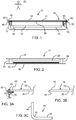
- Display device 10 comprising a display panel.
- Display device 10 comprises a cabinet 12 that houses the display device components including display panel 14, backlight unit 16 in the case of a liquid crystal display (LCD) device, and display cover plate 18.
- a bezel 19 may be positioned adjacent at least edge portions of display panel 14.
- An exemplary display panel 14 is shown in FIG. 2 , in this instance a simplified representation of an LCD display panel.
- Display panel 14 may comprise a first substrate 20, a second substrate 22, a sealing material 24 disposed between the first and second substrates that joins the first substrate to the second substrate, and one or more thin film layers, shown collectively as layer 26, disposed on one or both of the first and second substrates and, again in the case of an LCD device, a layer of liquid crystal material 28.
- display panel 14 may be any suitable display panel, including without limitation an LCD display panel, an organic light emitting diode display panel comprising an organic light emitting material, a plasma display panel, or the like, that is formed using one or more thin glass substrates.
- display cover plate 18 is configured as a planar glass sheet having a first major surface 30 that is planar, a second major surface 32 that is planar and substantially parallel with first major surface 30, and an edge surface 34 ( FIG. 3B depicts a portion of display cover plate 18 without edge bracket 40 for clarity) disposed between the first and second major surfaces and forming a perimeter of the display cover plate.
- Edge surface 34 may be planar, substantially planar, or edge surface 34 may be shaped.
- display cover plate may undergo grinding and/or polishing such that edge surface 34 may be curved, or at least have a curved portion, or edge surface 34 may have a projecting portion, an angular portion (one or more planar portions, or a combination of any of the foregoing shapes or portions thereof.
- a curved edge face, wherein the edge face gradually transitions to the major surfaces of the display cover plate avoids the formation of sharp corners than can be easily damaged.
- Display cover plate 18 is positioned between display panel 14 and the viewer or observer O of the image formed by display panel 14. In some instances display cover plate 18 may be adhered to display panel 14 via an adhesive layer 31 such as a refractive index-matched epoxy.
- display cover plate 18 may have a refractive index that matches or nearly matches the refractive index of the observer-side portion of display panel 14 (i.e. the surface of display panel 14 facing display cover plate 18) such that the display cover plate appears to be homogeneous with the display panel.
- Display cover plate 18 may be, for example, a chemically strengthened glass sheet, such as an ion-exchanged glass.
- edge bracket 40 to support and protect edge portions 42 of display cover plate 18.
- edge bracket 40 may comprise a radius portion 45 positioned between a surface of first portion 44 and second portion 46, as best seen with the aid of FIG. 3C .
- edge bracket 40 in some examples forms a closed loop having a rectangular perimeter so that the support bracket is shaped like a picture frame having length and width only slightly larger that the length and width dimensions of display cover plate 18. In such cases, edge bracket 40 defines a hollow interior. As seen in FIGS.
- a cross section of edge bracket 40 may generally be "L" shaped so that a first portion 44 of edge bracket 40 supports first major surface 30 of the display cover plate at edge portion 42 (i.e. from a side opposite observer O), and a second portion 46 perpendicular to first portion 44 that covers edge surface 34 of display cover plate edge portion 42.
- An adhesive layer 48 may be used between the display cover plate and the edge bracket to adhere the display cover plate within the edge bracket.
- Adhesive layer 48 may be selected so that upon curing, the adhesive retains a degree of resiliency.
- Adhesive layer 48 may comprise a double-sided adhesive tape.
- the thickness of the adhesive layer should be small. In some examples, the thickness of the adhesive layer is less than about 10 ⁇ m.
- a resilient gasket material such as natural or synthetic rubber or other resilient polymer, or a foam material may be positioned between the edge bracket and the display cover plate. The resilient material may be used in conjunction with one or more adhesive layers.
- Edge bracket 40 may be mounted to cabinet 12 using an optional mounting flange 50 attached to wall 52 of cabinet 12.
- Mounting flange 50 may be plastic or metal, but should be rigid in order to provide sufficient support for the edge bracket.
- Edge bracket 40 may be mounted to mounting flange 50 by way of clips, screws or any other suitable mounting method, including welding, soldering, or by way of an adhesive.
- second portion 46 of edge bracket 40 may be relatively thin in a dimension generally parallel with the major surfaces 30, 32 of display cover plate 18, being on the order of equal to or less than 2 mm, such as equal to or less than about 1 mm.
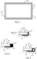
- FIG. 6 Shown in FIG. 6 is another embodiment of edge bracket 40 wherein the edge bracket only partially resembles an "L".
- first portion 44 of edge bracket 40 includes a surface that is substantially parallel with first major surface 30, however the edge bracket of FIG. 4 comprises a second portion 46 that includes a curved portion.
- FIG. 6 illustrates a "D" shaped second portion 46.
- a curved second portion 46 such as a "D" shaped second portion 46, still provides protection to the edges surfaces 34 of display cover plate 18, but being proportionately larger than the second portion of the "L" shaped edge bracket shown in FIG. 5 , a "D" shaped second portion 46 may provide enhanced protection.
- edge bracket 40 may comprise multiple materials, for example having a first portion 44 formed from metal to provide rigidity to the display cover plate supporting portion of the edge bracket, and a second portion 46 comprising a resilient material to mitigate against edge damage to the display cover plate.
- the "D" shaped portion of the edge bracket shown in FIG. 4 defines a hollow channel 62 that runs along an interior of the edge bracket, generally parallel with edge surface 34, so that a cross section comprises a more distinctive "D" shape.
- a hollow second portion 46 may be more resilient than a solid second portion 46, in effect forming a buckle zone where impact with second portion 46 may cause second portion 46 to collapse into the hollow channel and absorb the impact energy.
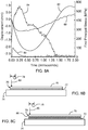
- FIG. 8A a graph is shown depicting the modeled displacement in millimeters of an impacted display cover plate 18 and calculated stress in MPa within the display cover plate, as a function of time in milliseconds, wherein zero time represents the instant of impact.
- Two configurations were modeled.
- a chemically strengthened glass sheet 70 having length and width dimensions of 150 mm x 150 mm is supported by a rubber pad 72, which in turn is supported on a metal table 74.
- the glass sheet is impacted at an impact angle perpendicular with the exposed surface 76 of the glass sheet within an edge portion 78 adjacent a perimeter of the glass sheet, as represented by the arrow 80.
- Curve 82 represents the modeled displacement at the center of the glass sheet
- curve 84 represents the modeled stress.
- a metal plate 86 is positioned between chemically-strengthened glass sheet 70 and rubber pad 72, and glass sheet 70 is again impacted in the same manner as in the first configuration.
- Curve 88 represents the modeled displacement of the glass sheet in the second configuration and curve 90 represents the modeled stress.
- the data from FIG. 8A show that in the first configuration, the glass undergoes a large maximum displacement from the rest position of about 2.25 mm (in absolute terms), and a similarly large stress, reaching a peak stress of approximately 550 MPa.
- the glass sheet undergoes a peak displacement of only about 0.75 mm, and a similarly small stress, on the order of about 100 MPa.
- the data indicate that the additional rigid support positioned behind the glass sheet prevents flexure of the glass sheet that can induce tensile stress into the edges of the glass sheet.
- a rigid edge bracket such as an edge bracket formed from metal (e.g. steel), can effectively reduce the displacement of a display cover plate and thereby reduce the tendency of the display cover plate to experience impact damage. Accordingly, another embodiment of the present disclosure is described in reference to FIGS. 9 - 11 .
- FIG. 9 is a perspective view of an edge bracket 100 having as a minimum a first portion 102 in the shape of a closed loop defining a cutout (hollow) region 104. That is, in some embodiments edge bracket 100 is a substantially planar, rectangular frame having a least one smooth major surface for placement adjacent to the display cover plate. Examples of suitable materials for forming edge bracket 100 include metal (e.g. steel, aluminum, titanium or other metals have high rigidity).
- FIG. 10 is a close-up cross sectional view of a portion of a display device 110 comprising edge bracket 100 disposed between display cover plate 18 and a portion of a cabinet 112. Cabinet may include a mounting flange, a shelf, or any other surface on which edge bracket 100 may be positioned and supported.
- display device 110 may further comprise a bumper member 114 disposed in a closed loop about a perimeter of the display cover plate.
- the bumper member protects the edge surface of the display cover plate from impact damage. Consequently, the bumper member may be formed, for example, from a resilient material.
- the bumper member may be a polymer material applied to the edge surface of the display cover plate, such as with an adhesive.
- Bumper member 114 may be a "D" shaped body as shown in FIG. 12 .
- the bumper member may include an open or closed hollow channel located within the body of the bumper member.
- the bumper member comprises a second portion of edge bracket 100, in that bumper member 114 is an integral part of edge bracket 100, or bumper member may be coupled to edge bracket 100, either directly, or via an adhesive layer 48.
Landscapes
- Physics & Mathematics (AREA)
- Nonlinear Science (AREA)
- Optics & Photonics (AREA)
- Mathematical Physics (AREA)
- Chemical & Material Sciences (AREA)
- Crystallography & Structural Chemistry (AREA)
- General Physics & Mathematics (AREA)
- Engineering & Computer Science (AREA)
- Plasma & Fusion (AREA)
- Devices For Indicating Variable Information By Combining Individual Elements (AREA)
- Joining Of Glass To Other Materials (AREA)
Applications Claiming Priority (2)
| Application Number | Priority Date | Filing Date | Title |
|---|---|---|---|
| US13/529,141 US8947866B2 (en) | 2012-06-21 | 2012-06-21 | Edge armored display cover plate |
| PCT/US2013/046583 WO2013192311A1 (en) | 2012-06-21 | 2013-06-19 | Cover plate in a display, which has a protective supporting bracket at its edge |
Publications (2)
| Publication Number | Publication Date |
|---|---|
| EP2864834A1 EP2864834A1 (en) | 2015-04-29 |
| EP2864834B1 true EP2864834B1 (en) | 2020-01-22 |
Family
ID=48748519
Family Applications (1)
| Application Number | Title | Priority Date | Filing Date |
|---|---|---|---|
| EP13734898.3A Active EP2864834B1 (en) | 2012-06-21 | 2013-06-19 | Cover plate in a display, which has a protective supporting bracket at its edge |
Country Status (7)
| Country | Link |
|---|---|
| US (1) | US8947866B2 (enExample) |
| EP (1) | EP2864834B1 (enExample) |
| JP (1) | JP6074498B2 (enExample) |
| KR (1) | KR101909329B1 (enExample) |
| CN (1) | CN104583846B (enExample) |
| TW (1) | TWI600358B (enExample) |
| WO (1) | WO2013192311A1 (enExample) |
Families Citing this family (28)
| Publication number | Priority date | Publication date | Assignee | Title |
|---|---|---|---|---|
| US8947866B2 (en) * | 2012-06-21 | 2015-02-03 | Corning Incorporated | Edge armored display cover plate |
| US20140092346A1 (en) | 2012-09-28 | 2014-04-03 | Apple Inc. | Borderless Display with Light-Bending Structures |
| JP6528685B2 (ja) * | 2013-11-15 | 2019-06-12 | Agc株式会社 | 粘着層付き透明面材および表示装置 |
| EP2916165B1 (en) * | 2014-03-05 | 2018-04-04 | LG Electronics Inc. | Curved mobile terminal |
| US9851827B2 (en) | 2014-05-28 | 2017-12-26 | Corning Incorporated | Touch-screen assembly with rigid interface between cover sheet and frame |
| CN104699300B (zh) * | 2015-03-05 | 2018-07-06 | 业成光电(深圳)有限公司 | 基板结构 |
| KR102274142B1 (ko) | 2015-03-10 | 2021-07-09 | 삼성디스플레이 주식회사 | 표시 장치 및 휴대용 단말기 |
| TW201642720A (zh) * | 2015-05-26 | 2016-12-01 | 明興光電股份有限公司 | 保護殼以及具觸控功能的保護殼 |
| US9575507B1 (en) * | 2015-09-02 | 2017-02-21 | Apple Inc. | Crack mitigation in an optically transparent exterior of a portable electronic device |
| US11451256B1 (en) * | 2015-12-03 | 2022-09-20 | Paul Beaulieu | Protective and functional layers for display screens |
| KR102554290B1 (ko) * | 2016-05-23 | 2023-07-13 | 삼성디스플레이 주식회사 | 표시 장치 |
| KR102753553B1 (ko) * | 2016-11-30 | 2025-01-10 | 엘지디스플레이 주식회사 | 폴더블 디스플레이 장치 |
| KR20180064626A (ko) * | 2016-12-05 | 2018-06-15 | 삼성디스플레이 주식회사 | 표시장치 |
| KR102590928B1 (ko) | 2017-01-09 | 2023-10-19 | 삼성전자주식회사 | 전자 장치 |
| CN107807714A (zh) * | 2017-10-19 | 2018-03-16 | 成都市宏山科技有限公司 | 一种新型摇摆型平板电脑 |
| JP2019133082A (ja) * | 2018-02-02 | 2019-08-08 | 株式会社ジャパンディスプレイ | 表示装置、表示装置の製造方法、および接合装置 |
| CN208256180U (zh) | 2018-04-11 | 2018-12-18 | Abb瑞士股份有限公司 | 显示器、电子设备和用于机器人的示教器 |
| JP6873486B2 (ja) * | 2018-08-06 | 2021-05-19 | 株式会社Joled | ディスプレイ表示装置 |
| KR102230731B1 (ko) * | 2018-11-28 | 2021-03-22 | 주식회사 포스코 | 디스플레이장치 |
| JP6988857B2 (ja) * | 2019-04-18 | 2022-01-05 | 株式会社デンソー | 車両用表示装置 |
| KR102689721B1 (ko) * | 2019-07-22 | 2024-07-29 | 엘지디스플레이 주식회사 | 디스플레이 장치 및 이를 포함하는 차량 |
| CN112038377B (zh) * | 2020-09-03 | 2023-11-24 | 深圳市源彩伟业科技有限公司 | 一种amoled显示屏和终端 |
| CN112185256B (zh) * | 2020-09-30 | 2023-01-24 | 武汉天马微电子有限公司 | 可折叠显示装置及其制备方法 |
| EP4192212A4 (en) * | 2021-01-27 | 2024-03-27 | Samsung Electronics Co., Ltd. | ELECTRONIC DEVICE WITH SEALING ELEMENT |
| CN113453452B (zh) * | 2021-05-24 | 2022-11-01 | 荣耀终端有限公司 | 一种电子设备 |
| CN114188285B (zh) * | 2021-11-18 | 2025-07-18 | Tcl华星光电技术有限公司 | 显示面板及显示面板的制作方法 |
| WO2023195739A1 (ko) * | 2022-04-04 | 2023-10-12 | 삼성전자 주식회사 | 디스플레이 구조 및 디스플레이 구조를 포함하는 전자 장치 |
| CN116006026A (zh) * | 2022-12-26 | 2023-04-25 | 珠海格力电器股份有限公司 | 显示机构及具有其的门锁设备 |
Citations (4)
| Publication number | Priority date | Publication date | Assignee | Title |
|---|---|---|---|---|
| US20090186552A1 (en) * | 2007-07-17 | 2009-07-23 | Sony Chemical & Information Device Corporation | Image display device and its manufacturing method |
| JP2009288671A (ja) * | 2008-05-30 | 2009-12-10 | Nec Corp | 電子機器の表示装置固定構造及び該構造を備える電子機器 |
| JP2010032653A (ja) * | 2008-07-25 | 2010-02-12 | Sony Corp | 電子機器 |
| WO2011084405A1 (en) * | 2009-12-17 | 2011-07-14 | 3M Innovative Properties Company | Display panel assembly and methods of making same |
Family Cites Families (18)
| Publication number | Priority date | Publication date | Assignee | Title |
|---|---|---|---|---|
| CN2367744Y (zh) * | 1998-08-05 | 2000-03-08 | 宁波华利电器塑料厂 | 消毒柜门封密封条 |
| JP2006006353A (ja) * | 2004-06-22 | 2006-01-12 | Total Print Yutaka Kogyo Kk | ツボ押し具 |
| JP3850847B2 (ja) * | 2004-06-28 | 2006-11-29 | 株式会社東芝 | 電子機器の液晶表示装置保護構造 |
| JP4304515B2 (ja) * | 2005-10-24 | 2009-07-29 | 船井電機株式会社 | 組付け構造、組付け方法、及びプラズマテレビ |
| CN101815594B (zh) | 2007-07-12 | 2012-09-19 | 苹果公司 | 用于将玻璃插入物一体地陷到金属边框中的方法及所生产的电子设备 |
| JP4462317B2 (ja) * | 2007-09-28 | 2010-05-12 | カシオ計算機株式会社 | 保護板一体型表示パネル |
| KR101058730B1 (ko) | 2007-09-28 | 2011-08-22 | 가시오게산키 가부시키가이샤 | 보호판을 일체적으로 한 표시소자 및 그것을 이용한 표시장치 |
| JP5188833B2 (ja) * | 2008-02-21 | 2013-04-24 | 株式会社ジャパンディスプレイイースト | 表示装置の製造方法 |
| JP2009258440A (ja) * | 2008-04-17 | 2009-11-05 | Funai Electric Co Ltd | 薄型表示装置 |
| JP5315965B2 (ja) * | 2008-12-11 | 2013-10-16 | カシオ計算機株式会社 | 保護板一体型表示パネル及びその製造方法 |
| JP5051158B2 (ja) | 2009-03-13 | 2012-10-17 | カシオ計算機株式会社 | 保護板一体型表示装置 |
| KR101130431B1 (ko) * | 2009-03-13 | 2012-03-28 | 가시오게산키 가부시키가이샤 | 보호판 일체형 표시장치 |
| US8456586B2 (en) | 2009-06-11 | 2013-06-04 | Apple Inc. | Portable computer display structures |
| JP5431138B2 (ja) * | 2009-12-10 | 2014-03-05 | 三洋電機株式会社 | 画像表示装置 |
| US9017566B2 (en) * | 2010-04-30 | 2015-04-28 | Corning Incorporated | Anti-glare surface treatment method and articles thereof |
| WO2013179815A1 (ja) * | 2012-05-29 | 2013-12-05 | シャープ株式会社 | 表示装置 |
| US20150168767A1 (en) * | 2012-06-11 | 2015-06-18 | Sharp Kabushiki Kaisha | Display device |
| US8947866B2 (en) * | 2012-06-21 | 2015-02-03 | Corning Incorporated | Edge armored display cover plate |
-
2012
- 2012-06-21 US US13/529,141 patent/US8947866B2/en not_active Expired - Fee Related
-
2013
- 2013-06-19 CN CN201380032717.8A patent/CN104583846B/zh not_active Expired - Fee Related
- 2013-06-19 JP JP2015518548A patent/JP6074498B2/ja not_active Expired - Fee Related
- 2013-06-19 KR KR1020157001267A patent/KR101909329B1/ko not_active Expired - Fee Related
- 2013-06-19 WO PCT/US2013/046583 patent/WO2013192311A1/en not_active Ceased
- 2013-06-19 EP EP13734898.3A patent/EP2864834B1/en active Active
- 2013-06-20 TW TW102121972A patent/TWI600358B/zh not_active IP Right Cessation
Patent Citations (4)
| Publication number | Priority date | Publication date | Assignee | Title |
|---|---|---|---|---|
| US20090186552A1 (en) * | 2007-07-17 | 2009-07-23 | Sony Chemical & Information Device Corporation | Image display device and its manufacturing method |
| JP2009288671A (ja) * | 2008-05-30 | 2009-12-10 | Nec Corp | 電子機器の表示装置固定構造及び該構造を備える電子機器 |
| JP2010032653A (ja) * | 2008-07-25 | 2010-02-12 | Sony Corp | 電子機器 |
| WO2011084405A1 (en) * | 2009-12-17 | 2011-07-14 | 3M Innovative Properties Company | Display panel assembly and methods of making same |
Also Published As
| Publication number | Publication date |
|---|---|
| KR101909329B1 (ko) | 2018-10-17 |
| TWI600358B (zh) | 2017-09-21 |
| US8947866B2 (en) | 2015-02-03 |
| CN104583846A (zh) | 2015-04-29 |
| JP2015527603A (ja) | 2015-09-17 |
| TW201408164A (zh) | 2014-02-16 |
| WO2013192311A1 (en) | 2013-12-27 |
| KR20150023035A (ko) | 2015-03-04 |
| US20130342971A1 (en) | 2013-12-26 |
| JP6074498B2 (ja) | 2017-02-01 |
| EP2864834A1 (en) | 2015-04-29 |
| CN104583846B (zh) | 2018-01-09 |
Similar Documents
| Publication | Publication Date | Title |
|---|---|---|
| EP2864834B1 (en) | Cover plate in a display, which has a protective supporting bracket at its edge | |
| JP5480860B2 (ja) | 曲面表示モジュール | |
| EP3176671B1 (en) | Display screen assembly and terminal | |
| US9374919B2 (en) | Insert molded device housings for portable electronic devices | |
| US20130335670A1 (en) | Planar display device | |
| EP2574978A2 (en) | Information processing apparatus | |
| US8960982B2 (en) | Electronic apparatus having a display unit | |
| US11416029B2 (en) | Electronic devices with thin display housings | |
| EP2875415B1 (en) | Display arrangement | |
| EP3321727B1 (en) | Display apparatus | |
| CN113126343B (zh) | 显示装置 | |
| EP3089140B1 (en) | Display apparatus | |
| US20120050640A1 (en) | Liquid crystal display device | |
| WO2013134621A1 (en) | Bezel-free display device including an acoustically coupled display cover plate | |
| KR102676813B1 (ko) | 디스플레이 모듈 및 이동 단말기 | |
| US20200026116A1 (en) | Display device and display apparatus | |
| JP2014130194A (ja) | 表示装置 | |
| CN112965291B (zh) | 一种显示装置及其背光模组 | |
| JP2001051608A (ja) | 表示装置 | |
| US20170343854A1 (en) | Liquid crystal display | |
| CN112700728A (zh) | 显示模组及电子设备 | |
| JP5724056B2 (ja) | 情報表示装置 | |
| WO2022083101A1 (zh) | 一种交互智能平板 | |
| KR20160083497A (ko) | 표시장치 및 그를 포함하는 세트 전자 장치 |
Legal Events
| Date | Code | Title | Description |
|---|---|---|---|
| PUAI | Public reference made under article 153(3) epc to a published international application that has entered the european phase |
Free format text: ORIGINAL CODE: 0009012 |
|
| 17P | Request for examination filed |
Effective date: 20150115 |
|
| AK | Designated contracting states |
Kind code of ref document: A1 Designated state(s): AL AT BE BG CH CY CZ DE DK EE ES FI FR GB GR HR HU IE IS IT LI LT LU LV MC MK MT NL NO PL PT RO RS SE SI SK SM TR |
|
| AX | Request for extension of the european patent |
Extension state: BA ME |
|
| DAX | Request for extension of the european patent (deleted) | ||
| 17Q | First examination report despatched |
Effective date: 20151005 |
|
| STAA | Information on the status of an ep patent application or granted ep patent |
Free format text: STATUS: EXAMINATION IS IN PROGRESS |
|
| GRAP | Despatch of communication of intention to grant a patent |
Free format text: ORIGINAL CODE: EPIDOSNIGR1 |
|
| STAA | Information on the status of an ep patent application or granted ep patent |
Free format text: STATUS: GRANT OF PATENT IS INTENDED |
|
| GRAS | Grant fee paid |
Free format text: ORIGINAL CODE: EPIDOSNIGR3 |
|
| GRAA | (expected) grant |
Free format text: ORIGINAL CODE: 0009210 |
|
| STAA | Information on the status of an ep patent application or granted ep patent |
Free format text: STATUS: THE PATENT HAS BEEN GRANTED |
|
| INTG | Intention to grant announced |
Effective date: 20191128 |
|
| AK | Designated contracting states |
Kind code of ref document: B1 Designated state(s): AL AT BE BG CH CY CZ DE DK EE ES FI FR GB GR HR HU IE IS IT LI LT LU LV MC MK MT NL NO PL PT RO RS SE SI SK SM TR |
|
| REG | Reference to a national code |
Ref country code: GB Ref legal event code: FG4D |
|
| REG | Reference to a national code |
Ref country code: CH Ref legal event code: EP |
|
| REG | Reference to a national code |
Ref country code: AT Ref legal event code: REF Ref document number: 1227276 Country of ref document: AT Kind code of ref document: T Effective date: 20200215 |
|
| REG | Reference to a national code |
Ref country code: IE Ref legal event code: FG4D |
|
| REG | Reference to a national code |
Ref country code: DE Ref legal event code: R096 Ref document number: 602013065287 Country of ref document: DE |
|
| REG | Reference to a national code |
Ref country code: NL Ref legal event code: MP Effective date: 20200122 |
|
| REG | Reference to a national code |
Ref country code: LT Ref legal event code: MG4D |
|
| PG25 | Lapsed in a contracting state [announced via postgrant information from national office to epo] |
Ref country code: NL Free format text: LAPSE BECAUSE OF FAILURE TO SUBMIT A TRANSLATION OF THE DESCRIPTION OR TO PAY THE FEE WITHIN THE PRESCRIBED TIME-LIMIT Effective date: 20200122 Ref country code: RS Free format text: LAPSE BECAUSE OF FAILURE TO SUBMIT A TRANSLATION OF THE DESCRIPTION OR TO PAY THE FEE WITHIN THE PRESCRIBED TIME-LIMIT Effective date: 20200122 Ref country code: FI Free format text: LAPSE BECAUSE OF FAILURE TO SUBMIT A TRANSLATION OF THE DESCRIPTION OR TO PAY THE FEE WITHIN THE PRESCRIBED TIME-LIMIT Effective date: 20200122 Ref country code: PT Free format text: LAPSE BECAUSE OF FAILURE TO SUBMIT A TRANSLATION OF THE DESCRIPTION OR TO PAY THE FEE WITHIN THE PRESCRIBED TIME-LIMIT Effective date: 20200614 Ref country code: NO Free format text: LAPSE BECAUSE OF FAILURE TO SUBMIT A TRANSLATION OF THE DESCRIPTION OR TO PAY THE FEE WITHIN THE PRESCRIBED TIME-LIMIT Effective date: 20200422 |
|
| PG25 | Lapsed in a contracting state [announced via postgrant information from national office to epo] |
Ref country code: HR Free format text: LAPSE BECAUSE OF FAILURE TO SUBMIT A TRANSLATION OF THE DESCRIPTION OR TO PAY THE FEE WITHIN THE PRESCRIBED TIME-LIMIT Effective date: 20200122 Ref country code: SE Free format text: LAPSE BECAUSE OF FAILURE TO SUBMIT A TRANSLATION OF THE DESCRIPTION OR TO PAY THE FEE WITHIN THE PRESCRIBED TIME-LIMIT Effective date: 20200122 Ref country code: LV Free format text: LAPSE BECAUSE OF FAILURE TO SUBMIT A TRANSLATION OF THE DESCRIPTION OR TO PAY THE FEE WITHIN THE PRESCRIBED TIME-LIMIT Effective date: 20200122 Ref country code: BG Free format text: LAPSE BECAUSE OF FAILURE TO SUBMIT A TRANSLATION OF THE DESCRIPTION OR TO PAY THE FEE WITHIN THE PRESCRIBED TIME-LIMIT Effective date: 20200422 Ref country code: IS Free format text: LAPSE BECAUSE OF FAILURE TO SUBMIT A TRANSLATION OF THE DESCRIPTION OR TO PAY THE FEE WITHIN THE PRESCRIBED TIME-LIMIT Effective date: 20200522 Ref country code: GR Free format text: LAPSE BECAUSE OF FAILURE TO SUBMIT A TRANSLATION OF THE DESCRIPTION OR TO PAY THE FEE WITHIN THE PRESCRIBED TIME-LIMIT Effective date: 20200423 |
|
| REG | Reference to a national code |
Ref country code: DE Ref legal event code: R097 Ref document number: 602013065287 Country of ref document: DE |
|
| PG25 | Lapsed in a contracting state [announced via postgrant information from national office to epo] |
Ref country code: RO Free format text: LAPSE BECAUSE OF FAILURE TO SUBMIT A TRANSLATION OF THE DESCRIPTION OR TO PAY THE FEE WITHIN THE PRESCRIBED TIME-LIMIT Effective date: 20200122 Ref country code: CZ Free format text: LAPSE BECAUSE OF FAILURE TO SUBMIT A TRANSLATION OF THE DESCRIPTION OR TO PAY THE FEE WITHIN THE PRESCRIBED TIME-LIMIT Effective date: 20200122 Ref country code: LT Free format text: LAPSE BECAUSE OF FAILURE TO SUBMIT A TRANSLATION OF THE DESCRIPTION OR TO PAY THE FEE WITHIN THE PRESCRIBED TIME-LIMIT Effective date: 20200122 Ref country code: EE Free format text: LAPSE BECAUSE OF FAILURE TO SUBMIT A TRANSLATION OF THE DESCRIPTION OR TO PAY THE FEE WITHIN THE PRESCRIBED TIME-LIMIT Effective date: 20200122 Ref country code: SM Free format text: LAPSE BECAUSE OF FAILURE TO SUBMIT A TRANSLATION OF THE DESCRIPTION OR TO PAY THE FEE WITHIN THE PRESCRIBED TIME-LIMIT Effective date: 20200122 Ref country code: SK Free format text: LAPSE BECAUSE OF FAILURE TO SUBMIT A TRANSLATION OF THE DESCRIPTION OR TO PAY THE FEE WITHIN THE PRESCRIBED TIME-LIMIT Effective date: 20200122 Ref country code: DK Free format text: LAPSE BECAUSE OF FAILURE TO SUBMIT A TRANSLATION OF THE DESCRIPTION OR TO PAY THE FEE WITHIN THE PRESCRIBED TIME-LIMIT Effective date: 20200122 Ref country code: ES Free format text: LAPSE BECAUSE OF FAILURE TO SUBMIT A TRANSLATION OF THE DESCRIPTION OR TO PAY THE FEE WITHIN THE PRESCRIBED TIME-LIMIT Effective date: 20200122 |
|
| REG | Reference to a national code |
Ref country code: AT Ref legal event code: MK05 Ref document number: 1227276 Country of ref document: AT Kind code of ref document: T Effective date: 20200122 |
|
| PLBE | No opposition filed within time limit |
Free format text: ORIGINAL CODE: 0009261 |
|
| STAA | Information on the status of an ep patent application or granted ep patent |
Free format text: STATUS: NO OPPOSITION FILED WITHIN TIME LIMIT |
|
| 26N | No opposition filed |
Effective date: 20201023 |
|
| REG | Reference to a national code |
Ref country code: DE Ref legal event code: R119 Ref document number: 602013065287 Country of ref document: DE |
|
| PG25 | Lapsed in a contracting state [announced via postgrant information from national office to epo] |
Ref country code: AT Free format text: LAPSE BECAUSE OF FAILURE TO SUBMIT A TRANSLATION OF THE DESCRIPTION OR TO PAY THE FEE WITHIN THE PRESCRIBED TIME-LIMIT Effective date: 20200122 Ref country code: MC Free format text: LAPSE BECAUSE OF FAILURE TO SUBMIT A TRANSLATION OF THE DESCRIPTION OR TO PAY THE FEE WITHIN THE PRESCRIBED TIME-LIMIT Effective date: 20200122 Ref country code: IT Free format text: LAPSE BECAUSE OF FAILURE TO SUBMIT A TRANSLATION OF THE DESCRIPTION OR TO PAY THE FEE WITHIN THE PRESCRIBED TIME-LIMIT Effective date: 20200122 |
|
| REG | Reference to a national code |
Ref country code: CH Ref legal event code: PL |
|
| PG25 | Lapsed in a contracting state [announced via postgrant information from national office to epo] |
Ref country code: SI Free format text: LAPSE BECAUSE OF FAILURE TO SUBMIT A TRANSLATION OF THE DESCRIPTION OR TO PAY THE FEE WITHIN THE PRESCRIBED TIME-LIMIT Effective date: 20200122 Ref country code: PL Free format text: LAPSE BECAUSE OF FAILURE TO SUBMIT A TRANSLATION OF THE DESCRIPTION OR TO PAY THE FEE WITHIN THE PRESCRIBED TIME-LIMIT Effective date: 20200122 |
|
| GBPC | Gb: european patent ceased through non-payment of renewal fee |
Effective date: 20200619 |
|
| PG25 | Lapsed in a contracting state [announced via postgrant information from national office to epo] |
Ref country code: LU Free format text: LAPSE BECAUSE OF NON-PAYMENT OF DUE FEES Effective date: 20200619 |
|
| REG | Reference to a national code |
Ref country code: BE Ref legal event code: MM Effective date: 20200630 |
|
| PG25 | Lapsed in a contracting state [announced via postgrant information from national office to epo] |
Ref country code: FR Free format text: LAPSE BECAUSE OF NON-PAYMENT OF DUE FEES Effective date: 20200630 Ref country code: CH Free format text: LAPSE BECAUSE OF NON-PAYMENT OF DUE FEES Effective date: 20200630 Ref country code: LI Free format text: LAPSE BECAUSE OF NON-PAYMENT OF DUE FEES Effective date: 20200630 Ref country code: GB Free format text: LAPSE BECAUSE OF NON-PAYMENT OF DUE FEES Effective date: 20200619 Ref country code: IE Free format text: LAPSE BECAUSE OF NON-PAYMENT OF DUE FEES Effective date: 20200619 |
|
| PG25 | Lapsed in a contracting state [announced via postgrant information from national office to epo] |
Ref country code: DE Free format text: LAPSE BECAUSE OF NON-PAYMENT OF DUE FEES Effective date: 20210101 Ref country code: BE Free format text: LAPSE BECAUSE OF NON-PAYMENT OF DUE FEES Effective date: 20200630 |
|
| PG25 | Lapsed in a contracting state [announced via postgrant information from national office to epo] |
Ref country code: TR Free format text: LAPSE BECAUSE OF FAILURE TO SUBMIT A TRANSLATION OF THE DESCRIPTION OR TO PAY THE FEE WITHIN THE PRESCRIBED TIME-LIMIT Effective date: 20200122 Ref country code: MT Free format text: LAPSE BECAUSE OF FAILURE TO SUBMIT A TRANSLATION OF THE DESCRIPTION OR TO PAY THE FEE WITHIN THE PRESCRIBED TIME-LIMIT Effective date: 20200122 Ref country code: CY Free format text: LAPSE BECAUSE OF FAILURE TO SUBMIT A TRANSLATION OF THE DESCRIPTION OR TO PAY THE FEE WITHIN THE PRESCRIBED TIME-LIMIT Effective date: 20200122 |
|
| PG25 | Lapsed in a contracting state [announced via postgrant information from national office to epo] |
Ref country code: MK Free format text: LAPSE BECAUSE OF FAILURE TO SUBMIT A TRANSLATION OF THE DESCRIPTION OR TO PAY THE FEE WITHIN THE PRESCRIBED TIME-LIMIT Effective date: 20200122 Ref country code: AL Free format text: LAPSE BECAUSE OF FAILURE TO SUBMIT A TRANSLATION OF THE DESCRIPTION OR TO PAY THE FEE WITHIN THE PRESCRIBED TIME-LIMIT Effective date: 20200122 |