EP2862830A1 - Device and method for moving a transport element of a freight or passenger elevator - Google Patents
Device and method for moving a transport element of a freight or passenger elevator Download PDFInfo
- Publication number
- EP2862830A1 EP2862830A1 EP20140189301 EP14189301A EP2862830A1 EP 2862830 A1 EP2862830 A1 EP 2862830A1 EP 20140189301 EP20140189301 EP 20140189301 EP 14189301 A EP14189301 A EP 14189301A EP 2862830 A1 EP2862830 A1 EP 2862830A1
- Authority
- EP
- European Patent Office
- Prior art keywords
- cylinder
- guide
- telescopic cylinder
- partial
- guide device
- Prior art date
- Legal status (The legal status is an assumption and is not a legal conclusion. Google has not performed a legal analysis and makes no representation as to the accuracy of the status listed.)
- Granted
Links
- 238000000034 method Methods 0.000 title claims abstract description 11
- 230000033001 locomotion Effects 0.000 claims abstract description 68
- 230000001419 dependent effect Effects 0.000 claims description 5
- 238000003780 insertion Methods 0.000 claims description 4
- 230000037431 insertion Effects 0.000 claims description 4
- 230000001105 regulatory effect Effects 0.000 claims description 2
- 230000001133 acceleration Effects 0.000 description 4
- 238000004519 manufacturing process Methods 0.000 description 4
- 239000010720 hydraulic oil Substances 0.000 description 3
- 238000013461 design Methods 0.000 description 2
- 238000001514 detection method Methods 0.000 description 2
- 239000012530 fluid Substances 0.000 description 2
- 238000003754 machining Methods 0.000 description 2
- 238000012549 training Methods 0.000 description 2
- XAGFODPZIPBFFR-UHFFFAOYSA-N aluminium Chemical compound [Al] XAGFODPZIPBFFR-UHFFFAOYSA-N 0.000 description 1
- 229910052782 aluminium Inorganic materials 0.000 description 1
- 238000009412 basement excavation Methods 0.000 description 1
- 230000033228 biological regulation Effects 0.000 description 1
- 230000008878 coupling Effects 0.000 description 1
- 238000010168 coupling process Methods 0.000 description 1
- 238000005859 coupling reaction Methods 0.000 description 1
- 238000005520 cutting process Methods 0.000 description 1
- 238000009826 distribution Methods 0.000 description 1
- 230000007613 environmental effect Effects 0.000 description 1
- 238000009434 installation Methods 0.000 description 1
- 238000012423 maintenance Methods 0.000 description 1
- 239000000463 material Substances 0.000 description 1
- 239000000203 mixture Substances 0.000 description 1
- 239000003921 oil Substances 0.000 description 1
- 230000003068 static effect Effects 0.000 description 1
- 238000003860 storage Methods 0.000 description 1
- 239000000725 suspension Substances 0.000 description 1
Images


Classifications
-
- B—PERFORMING OPERATIONS; TRANSPORTING
- B66—HOISTING; LIFTING; HAULING
- B66B—ELEVATORS; ESCALATORS OR MOVING WALKWAYS
- B66B9/00—Kinds or types of lifts in, or associated with, buildings or other structures
- B66B9/04—Kinds or types of lifts in, or associated with, buildings or other structures actuated pneumatically or hydraulically
Abstract
Die Erfindung betrifft eine Vorrichtung (1) zum Bewegen eines Transportelements eines Aufzugs, wobei die Vorrichtung (1) mindestens einen Teleskopzylinder (3) umfasst, wobei der Teleskopzylinder (3) mehrere Teilzylinder (4a, 4b, 4c, 4d) umfasst, wobei das Transportelement mit einem freien Ende (6) des Teleskopzylinders (6) mechanisch verbindbar ist, wobei die Vorrichtung (1) weiter mindestens eine Führungsvorrichtung (7, 8) zur Führung mindestens eines Teilzylinders (4a, 4b, 4c, 4d) umfasst, wobei mittels der Führungsvorrichtung (7, 8) eine Bewegung des mindestens einen Teilzylinders (4a, 4b, 4c, 4d) in und entgegen einer Hubrichtung des Teleskopzylinders (3) führbar ist, wobei die Führungsvorrichtung (7, 8) oder mindestens ein Führungselement (11a,..., 11i) der Führungsvorrichtung (7, 8) zur Führung der Bewegung des mindestens einen Teilzylinders (4a, 4b, 4c, 4d) mit zumindest einem Teilabschnitt einer äußeren Oberfläche des mindestens einen Teilzylinders (4a, 4b, 4c, 4d) wechselwirkt, sowie ein Verfahren zum Bewegen eines Transportelements.The invention relates to a device (1) for moving a transport element of an elevator, wherein the device (1) comprises at least one telescopic cylinder (3), the telescopic cylinder (3) comprising a plurality of partial cylinders (4a, 4b, 4c, 4d) Transport element with a free end (6) of the telescopic cylinder (6) is mechanically connectable, wherein the device (1) further comprises at least one guide device (7, 8) for guiding at least one part cylinder (4a, 4b, 4c, 4d), wherein means a movement of the at least one partial cylinder (4a, 4b, 4c, 4d) in and against a stroke direction of the telescopic cylinder (3) can be guided, wherein the guide device (7, 8) or at least one guide element (11a, , 11i) of the guide device (7, 8) for guiding the movement of the at least one partial cylinder (4a, 4b, 4c, 4d) with at least one partial section of an outer surface of the at least one partial cylinder (4a, 4b, 4c, 4d). w echselwirkt, as well as a method for moving a transport element.
Description
Die Erfindung betrifft eine Vorrichtung und ein Verfahren zum Bewegen eines Transportelements eines Last- oder Personenaufzugs.The invention relates to a device and a method for moving a transport element of a load or passenger elevator.
Aufzüge zum Transportieren von Personen oder Lasten werden üblicherweise mittels Elektromotoren betrieben, die über Seilzüge mechanisch mit einer Kabine des Aufzugs gekoppelt sind. Weiterhin existieren Aufzugsysteme, in welchen Hydraulikzylinder benutzt werden, die über Umlenkrollen Seilzüge bewegen. In derartigen Aufzugsystemen hängt die Kabine an den entsprechenden Seilzügen und Umlenkrollen.Lifts for transporting people or loads are usually operated by electric motors, which are mechanically coupled via cables to a cabin of the elevator. Furthermore, there are elevator systems in which hydraulic cylinders are used, which move over pulleys cables. In such elevator systems, the cab hangs on the corresponding pulleys and pulleys.
Weiter müssen in solchen Aufzugsystemen grundsätzlich Absturzsicherungen vorhanden sein. So muss beispielsweise im Fall eines Bruches eines Tragseils die Kabine nach kurzer Zeit in einer sicheren Lage zum Stehen kommen. Weiterhin darf eine definierte Geschwindigkeit bei einer Aufwärtsbewegung oder bei einer Abwärtsbewegung der Kabine nie überschritten werden. Die Sicherheitssysteme sind relativ aufwändig zu fertigen, kostenintensiv und müssen regelmäßig gewartet werden, was zu erheblichen Folgekosten führt.Furthermore, fall protection devices must generally be present in such elevator systems. For example, in the event of a rupture of a suspension cable, the cabin must come to a safe stop in a short time. Furthermore, a defined speed must never be exceeded during an upward movement or during a downward movement of the cabin. The security systems are relatively complex to manufacture, costly and must be maintained regularly, resulting in significant costs.
Die
Die
Es stellt sich das technische Problem, ein Verfahren und eine Vorrichtung zum Bewegen eines Transportelements eines Aufzugs, zu schaffen, welche eine zuverlässige und sichere Auf- und Abwärtsbewegung eines, insbesondere belasteten, Transportelements gewährleisten, wobei ein Bauraumbedarf sowie Herstellungskosten minimiert werden. Die Lösung des technischen Problems ergibt sich durch die Gegenstände mit den Merkmalen der Ansprüche 1 und 12. Weitere vorteilhafte Ausgestaltungen der Erfindung ergeben sich durch die Unteransprüche.This raises the technical problem of providing a method and a device for moving a transport element of an elevator, which ensure a reliable and safe up and down movement of a, in particular loaded, transport element, wherein a space requirement and manufacturing costs are minimized. The solution of the technical problem results from the objects with the features of
Es ist eine Grundidee der Erfindung, eine Aufwärts- und Abwärtsbewegung von Teilzylindern eines Teleskopzylinders durch eine Führungsvorrichtung vorzusehen, wobei diese Führungsvorrichtung oder Führungselemente der Führungsvorrichtung unmittelbar mit Mantelflächen der Teilzylinder wechselwirken, um die vorhergehend erläuterte Führung zu ermöglichen. Somit kann in vorteilhafter Weise, insbesondere bei großen Hublängen, ein Ausknicken der einzelnen Teilzylinder sicher vermieden werden.It is a basic idea of the invention to provide an upward and downward movement of sub-cylinders of a telescopic cylinder by a guide device, said guide device or guide elements of the guide device interact directly with lateral surfaces of the sub-cylinder to enable the previously explained guide. Thus, in an advantageous manner, in particular for long stroke lengths, buckling of the individual partial cylinders can be reliably avoided.
Vorgeschlagen wird eine Vorrichtung zum Bewegen eines Transportelements eines Personen- oder Lastaufzugs. Im Sinne der Erfindung beschreibt das Transportelement des Aufzugs ein Element zum Transportieren von Personen und/oder Lasten. Somit umfasst dieser Begriff z.B. eine Kabine, eine Plattform oder einen Fahrkorb. Selbstverständlich ist die vorgeschlagene Vorrichtung aber auch zum Bewegen aller anderen Arten von Lasten einsetzbar.Proposed is a device for moving a transport element of a passenger or freight elevator. For the purposes of the invention, the transport element of the elevator describes an element for transporting persons and / or loads. Thus, this term includes e.g. a cabin, a platform or a car. Of course, the proposed device but also for moving all other types of loads used.
Die Vorrichtung dient somit zum Bewegen des Transportelements in einer Aufwärtsrichtung, insbesondere einer vertikalen Richtung, und entgegen der Aufwärtsrichtung, also entgegen der vertikalen Richtung. Die vertikale Richtung kann hierbei senkrecht zu einer (ebenen) Erdoberfläche orientiert sein. Insbesondere kann die vertikale Richtung entgegengesetzt zu einer Richtung einer Gewichtskraft, die z.B. auf das Transportelement wirkt, orientiert sein. Die Vorrichtung dient zum Bewegen des Transportelements in einem belasteten Zustand, z. B. wenn eine Last am / im / auf dem Transportelement angeordnet ist, als auch in einem unbelasteten Zustand.The device thus serves to move the transport element in an upward direction, in particular a vertical direction, and counter to the upward direction, ie opposite to the vertical direction. The vertical direction can be oriented perpendicular to a (plane) earth surface. In particular, the vertical direction may be opposite to a direction of a gravitational force, e.g. acts on the transport element, be oriented. The device is used to move the transport element in a loaded state, for. B. when a load on / in / on the transport element is arranged, as well as in an unloaded state.
Die Vorrichtung umfasst mindestens einen Teleskopzylinder. Der Teleskopzylinder umfasst mehrere Teilzylinder. Die Teilzylinder sind hierbei in bekannter Weise ineinander verschiebbar. Insbesondere haben die Teilzylinder unterschiedliche aufeinander abgestimmte Außendurchmesser. Bei einem Ausfahren des Teleskopzylinders bewegen sich die einzelnen Teilzylinder sequenziell aus dem nächstgrößeren Teilzylinder heraus, in welchem sie im eingefahrenen Zustand angeordnet sind. Dementsprechend bewegen sich die Teilzylinder beim Einfahren wieder in diesen nächstgrößeren Teilzylinder hinein. Der Teleskopzylinder kann hierbei zwei oder mehr, insbesondere zehn, Teilzylinder umfassen. Vorzugsweise ist ein Verhältnis von einer maximal erreichbaren Hublänge zu einer Baulänge des Teleskopzylinders im eingefahrenen Zustand größer als oder gleich Zehn. Dies ermöglicht in vorteilhafter Weise ein gutes Verhältnis von Bauraum zu der maximalen Hublänge. Die maximale Hublänge bezeichnet hierbei eine Länge des Teleskopzylinders im vollständig ausgefahrenen Zustand.The device comprises at least one telescopic cylinder. The telescopic cylinder comprises several partial cylinders. The sub-cylinders are hereby slidable in a known manner. In particular, the partial cylinders have different coordinated outer diameter. Upon extension of the telescopic cylinder, the individual sub-cylinders move sequentially out of the next larger sub-cylinder, in which they are arranged in the retracted state. Accordingly, the partial cylinder move when retracting again in this next larger part of the cylinder. The telescopic cylinder may in this case comprise two or more, in particular ten, partial cylinders. Preferably, a ratio of a maximum achievable stroke length to a length of the telescopic cylinder in the retracted state is greater than or equal to ten. This advantageously allows a good ratio of installation space to the maximum stroke length. The maximum stroke length here denotes a length of the telescopic cylinder in the fully extended state.
Selbstverständlich kann die vorgeschlagene Vorrichtung auch mindestens einen Aktor umfassen, der das Aus- und/oder Einfahren des mindestens einen Teleskopzylinders unmittelbar oder mittelbar bewirkt. Vorzugsweise kann die Vorrichtung mindestens eine Pumpe umfassen, mittels derer ein Druck eines Betriebsmittels in einem Innenvolumen des Teleskopzylinders einstellbar ist. Durch das Einstellen des Druckes kann hierbei das vorhergehend erläuterte Ausfahren des Teleskopzylinders bewirkt werden. Ein Einfahren des Teleskopzylinders kann ebenfalls durch das Einstellen des Druckes, insbesondere eines Unterdruckes, bewirkt werden. Alternativ oder kumulativ kann das Einfahren jedoch auch über eine Gewichtskraft des Transportelements und / oder einer Last bewirkt werden. Dies wird nachfolgend näher erläutert.Of course, the proposed device may also comprise at least one actuator which causes the extension and / or retraction of the at least one telescopic cylinder directly or indirectly. Preferably, the device may comprise at least one pump by means of which a pressure of a resource in an inner volume of the telescopic cylinder is adjustable. By adjusting the pressure in this case, the previously explained extension of the telescopic cylinder can be effected. A retraction of the telescopic cylinder can also be effected by adjusting the pressure, in particular a negative pressure. Alternatively or cumulatively, however, the retraction can also be effected via a weight force of the transport element and / or a load. This will be explained in more detail below.
Vorzugsweise kann die Pumpe einen Druck bis zu 16 bar erzeugen.Preferably, the pump can generate a pressure up to 16 bar.
Selbstverständlich kann die Vorrichtung auch ein Wegerfassungssystem zur Bestimmung einer Position des freien Endes des Teleskopzylinders bzw. einer aktuellen Hublänge des Teleskopzylinders umfassen. In Abhängigkeit eines Ausgangssignals der Wegerfassungseinrichtung kann dann in vorteilhafter Weise eine wegabhängige Regelung des Aktors, insbesondere des von der Pumpe bereitgestellten Druckes, erfolgen.Of course, the device may also include a path detection system for determining a position of the free end of the telescopic cylinder or a current stroke length of the telescopic cylinder. Depending on an output signal of the path detection device can then be carried out advantageously a path-dependent control of the actuator, in particular the pressure provided by the pump.
Weiter ist das Transportelement mit einem freien Ende des Teleskopzylinders mechanisch verbindbar. Das Transportelement kann z.B. starr mit dem freien Ende, z.B. über weitere mechanische Koppelelemente, verbunden werden.Further, the transport element is mechanically connectable to a free end of the telescopic cylinder. The transport element may e.g. rigid with the free end, e.g. be connected via other mechanical coupling elements.
Weiter umfasst die Vorrichtung mindestens eine Führungsvorrichtung zur Führung mindestens eines Teilzylinders, wobei mittels der Führungsvorrichtung eine Bewegung des mindestens einen Teilzylinders in und entgegen einer Hubrichtung des Teleskopzylinders führbar ist. Die Hubrichtung bezeichnet hierbei eine Richtung der Bewegung beim Ausfahren des Teleskopzylinders und kann vorzugsweise der vorhergehend erläuterten vertikalen Richtung entsprechen.Furthermore, the device comprises at least one guide device for guiding at least one partial cylinder, wherein by means of the guide device, a movement of the at least one partial cylinder in and against a stroke direction of the telescopic cylinder can be guided. The stroke direction here denotes a direction of Movement during extension of the telescopic cylinder and may preferably correspond to the previously explained vertical direction.
Die Führungsvorrichtung kann eine Höhe aufweisen, die zumindest einem vorbestimmten Anteil, vorzugsweise der vollständigen Höhe bzw. Länge des Teleskopzylinders im vollständig ausgefahrenen Zustand, entspricht. Der vorbestimmte Anteil kann aber auch in einem Bereich von 70 % (einschließlich) bis 100 % (ausschließlich) der Höhe des Teleskopzylinders im vollständig ausgefahrenen Zustand liegen. Insbesondere ist die Führungsvorrichtung eine in ihren Abmessungen, insbesondere ihrer Höhe, unveränderliche Vorrichtung. Dies bedeutet, dass die Führungsvorrichtung nicht ein- oder ausziehbar ist.The guide device may have a height that corresponds to at least a predetermined proportion, preferably the complete height or length of the telescopic cylinder in the fully extended state. However, the predetermined proportion may also be in a range of 70% (inclusive) to 100% (exclusive) of the height of the telescopic cylinder in the fully extended condition. In particular, the guide device is one in their dimensions, in particular their height, immutable device. This means that the guide device is not retractable or extendable.
Die Führungsvorrichtung kann insbesondere auch derart ausgestaltet sein, dass eine Bewegung des mindestens einen Teilzylinders in einer von der Hubrichtung des Teleskopzylinders abweichenden Richtung verhindert wird. Dies bedeutet, dass eine solche abweichende Bewegung nicht oder nur in einem minimalen Maße zugelassen wird.The guide device can in particular also be designed such that a movement of the at least one partial cylinder is prevented in a direction deviating from the stroke direction of the telescopic cylinder. This means that such a deviating movement is not permitted or only to a minimum extent.
Die Führungsvorrichtung kann ein oder, vorzugsweise, mehrere Führungselement(e) aufweisen oder ausbilden. Zur Führung der Bewegung des mindestens einen Teilzylinders wechselwirkt die Führungsvorrichtung oder das mindestens eine Führungselement der Führungsvorrichtung mit zumindest einem Teilabschnitt einer äußeren Oberfläche des mindestens einen, insbesondere beweglichen, Teilzylinders. Die äußere Oberfläche des mindestens einen Teilzylinders kann insbesondere eine Mantelfläche des Teilzylinders sein.The guide device may comprise or form one or, preferably, a plurality of guide elements. To guide the movement of the at least one partial cylinder, the guide device or the at least one guide element of the guide device interacts with at least one partial section of an outer surface of the at least one, in particular movable, partial cylinder. The outer surface of the at least one partial cylinder can in particular be a lateral surface of the partial cylinder.
Im Sinne der Erfindung kann wechselwirken bedeuten, dass eine in oder entgegen die Hubrichtung gerichtete Kraft nicht oder nur in einem geringen Maße von dem Teilzylinder über die äußere Oberfläche des Teilzylinders auf die Führungsvorrichtung oder das mindestens eine Führungselement übertragen wird. Kräfte, deren Richtung von der Hubrichtung abweichen, werden jedoch von dem mindestens einen Teilzylinder über die äußere Oberfläche auf oder in das Führungselement übertragen. In diesem Fall kann die Führungsvorrichtung oder das mindestens eine Führungselement eine in ihrer Richtung entgegengesetzte und vom Betrag her gleiche Gegenkraft bereitstellen, die auf die äußere Oberfläche des mindestens einen Teilzylinders übertragen wird. Somit erfolgt keine oder nur eine minimale Bewegung des Teilzylinders in einer von der Hubrichtung abweichenden Richtung. Dies bedeutet, dass die Führungsvorrichtung bzw. das Führungselement die Bewegung des Teilzylinders über seine oder an seiner äußere(n) Oberfläche führt.For the purposes of the invention may mean interacting that a force directed in or against the stroke direction is not transmitted or only to a small extent from the sub-cylinder on the outer surface of the sub-cylinder on the guide device or the at least one guide element. Forces whose direction deviate from the stroke direction, however, are transferred from the at least one partial cylinder via the outer surface on or in the guide element. In this case, the guide device or the at least one guide element can provide an opposing force which is opposite in direction and equal in magnitude and which is transmitted to the outer surface of the at least one sub-cylinder. Thus, no or only a minimal movement of the sub-cylinder takes place in one of the stroke direction different direction. This means that the guide device or the guide element guides the movement of the sub-cylinder over its or on its outer (s) surface.
Wird der mindestens eine Teilzylinder durch die Führungsvorrichtung geführt, d.h. wechselwirkt der Teilzylinder mit der Führungsvorrichtung, so kann ein Abstand zwischen der äußeren Oberfläche des mindestens einen Teilzylinders und dem mit dieser äußeren Oberfläche wechselwirkenden Abschnitts der Führungsvorrichtung kleiner als ein vorbestimmter oder gleich einem vorbestimmten Maximalabstand sein, wobei der Maximalabstand beispielsweise 0.5mm oder 0.2mm betragen kann. Der Abstand kann hierbei einen Abstand entlang einer Richtung, die orthogonal zu der äußeren Oberfläche des mindestens einen Teilzylinders orientiert ist, bezeichnen.If the at least one partial cylinder is guided by the guide device, i. when the sub-cylinder interacts with the guide device, a distance between the outer surface of the at least one sub-cylinder and the portion of the guide device interacting with this outer surface may be less than a predetermined or equal to a predetermined maximum distance, the maximum distance being 0.5mm or 0.2mm, for example can. The distance may in this case denote a distance along a direction which is oriented orthogonally to the outer surface of the at least one partial cylinder.
Die Führungsvorrichtung oder das mindestens eine Führungselement kann insbesondere als Lagerelement ausgebildet sein. Weiter insbesondere kann die Führungsvorrichtung oder das mindestens eine Führungselement eine Gleitlagerung des Teilzylinders ermöglichen. Hierzu können Materialien des Teilzylinders und der Führungsvorrichtung bzw. des Führungselements derart gewählt werden, dass ein minimaler Haft- und/oder Gleitreibungskoeffizient zwischen der äußeren Oberfläche und einer mit der äußeren Oberfläche wechselwirkenden Oberfläche, die auch als Führungsfläche bezeichnet werden kann, der Führungsvorrichtung oder des Führungselements bereitgestellt wird. Somit wird in vorteilhafter Weise eine kostengünstige und wartungsarme oder sogar wartungsfreie Führung bereitgestellt.The guide device or the at least one guide element may in particular be designed as a bearing element. Further, in particular, the guide device or the at least one guide element allow a sliding bearing of the sub-cylinder. For this purpose, materials of the sub-cylinder and the guide device or the guide element can be selected such that a minimum coefficient of adhesion and / or sliding friction between the outer surface and a surface interacting with the outer surface, which may also be referred to as a guide surface, the guide device or the Guiding element is provided. Thus, an inexpensive and low-maintenance or even maintenance-free guidance is provided in an advantageous manner.
Neben einer Gleitlagerung sind selbstverständlich auch andere Lagerungen vorstellbar, beispielsweise eine Rollenlagerung.In addition to a slide bearing, of course, other bearings are conceivable, for example, a roller bearing.
Z.B. kann der mindestens eine Teilzylinder aus Aluminium ausgebildet sein. Eine Führungsfläche der Führungsvorrichtung oder des mindestens einen Führungselements kann insbesondere hart eloxiert sein.For example, the at least one partial cylinder may be formed from aluminum. A guide surface of the guide device or of the at least one guide element may in particular be hard anodized.
Somit wird eine in Bezug auf den mindestens einen Teilzylinder von außen angreifende Führung vorgeschlagen, wobei der mindestens eine Teilzylinder das in seiner Bewegung geführte Element darstellt und wobei die Führung unmittelbar über die äußere Oberfläche des Teilzylinders erfolgt. Zur Führung kann eine formschlüssige Verbindung zwischen dem mindestens einen Teilzylinder und der Führungsvorrichtung oder dem mindestens einen Führungselement der Führungsvorrichtung während der Bewegung hergestellt werden oder sein, wobei die formschlüssige Verbindung eine Bewegung des mindestens einen Teilzylinders in oder entgegen der Hubrichtung zulässt, in davon abweichende Richtungen aber minimiert oder nicht zulässt.Thus, a guide is proposed which engages with respect to the at least one sub-cylinder from the outside, wherein the at least one sub-cylinder represents the guided element in its movement and wherein the guide takes place directly over the outer surface of the sub-cylinder. For guidance, a positive connection between the at least one sub-cylinder and the guide device or the at least one guide element of the guide device are made or be during the movement, wherein the positive connection allows movement of the at least one sub-cylinder in or against the stroke direction, but minimizes or does not allow in deviating directions.
Selbstverständlich kann die Vorrichtung auch einen ersten und einen weiteren Teleskopzylinder umfassen. In diesem Fall kann die Vorrichtung eine erste Führungsvorrichtung zur Führung mindestens eines Teilzylinders des ersten Teleskopzylinders und eine weitere Führungsvorrichtung zur Führung mindestens eines Teilzylinders des weiteren Teleskopzylinders umfassen. An freien Enden der Teleskopzylinder kann ein Verbindungselement zur Verbindung der freien Enden befestigt sein, welches sich zwischen den freien Enden erstreckt. Das Transportelement kann in diesem Fall an dem Verbindungselement befestigbar sein. Hierdurch ergibt sich in vorteilhafter Weise eine verbesserte Lastverteilung und Lagerung sowie eine verbesserte und symmetrische Krafteinleitung zum Bewegen des Transportelements.Of course, the device may also comprise a first and a further telescopic cylinder. In this case, the device may comprise a first guide device for guiding at least one sub-cylinder of the first telescopic cylinder and a further guide device for guiding at least one sub-cylinder of the further telescopic cylinder. At free ends of the telescopic cylinder, a connecting element for connecting the free ends may be attached, which extends between the free ends. The transport element can be fastened to the connecting element in this case. This results in an advantageous manner an improved load distribution and storage and an improved and symmetrical force introduction for moving the transport element.
Insgesamt ergibt sich in vorteilhafter Weise, dass durch die Führungsvorrichtung ein Ausknicken des Teilzylinders, insbesondere während des Ausfahrens oder im ausgefahrenen Zustand, verhindert wird. Gleichzeitig wird durch die Führungsvorrichtung das Bewegen des Transportelements in einer gewünschten Richtung sicher gewährleistet. Somit wird einerseits eine gewünschte Bewegung des Teleskopzylinders sichergestellt. Andererseits kann die Führungsvorrichtung ebenfalls sicherstellen, dass der entsprechende Teilzylinder im vollständig ausgefahrenen Zustand des Teilzylinders sicher gehalten wird und nicht ausknickt.Overall, it results in an advantageous manner that a buckling of the part of the cylinder, in particular during the extension or in the extended state, is prevented by the guide device. At the same time, the movement of the transport element in a desired direction is ensured by the guide device. Thus, on the one hand a desired movement of the telescopic cylinder is ensured. On the other hand, the guide device can also ensure that the corresponding part of the cylinder is held securely in the fully extended state of the sub-cylinder and does not buckle.
Die vorgeschlagene Vorrichtung ermöglicht in vorteilhafter Weise die Verwendung von filigran ausgebildeten Teilzylindern. Dies wiederum reduziert in vorteilhafter Weise Herstellungskosten und einen Bauraumbedarf der vorgeschlagenen Vorrichtung.The proposed device advantageously allows the use of filigree sub-cylinders. This in turn reduces manufacturing costs and a space requirement of the proposed device in an advantageous manner.
Auch ermöglicht die vorgeschlagene Vorrichtung, dass Teleskopzylinder mit sehr großen maximalen Hublängen verwendet werden können, wobei ein Ausknicken auch bei großen Längen sicher verhindert wird.Also, the proposed device allows telescopic cylinders with very large maximum stroke lengths can be used, with a buckling is reliably prevented even at long lengths.
Weiter umfasst die Führungsvorrichtung ein Trägerprofil, wobei das mindestens eineFurthermore, the guide device comprises a carrier profile, wherein the at least one
Führungselement an dem Trägerprofil befestigt ist oder von dem Trägerprofil ausgebildet wird. Das Trägerprofil kann hierbei die vorhergehend erläuterte Höhe der Führungsvorrichtung aufweisen. Das Trägerprofil kann insbesondere ein Hohlprofil sein, wobei in einem Innenvolumen des Hohlprofils das mindestens eine Führungselement angeordnet ist. Entsprechend bewegt sich der Teleskopzylinder ebenfalls in einem Innenvolumen des Hohlprofils. Das Trägerprofil kann hierbei mechanisch starr mit einem Befestigungsbereich, insbesondere einem Fundament, verbunden sein. Das Trägerprofil kann auch das Führungselement sein. Insbesondere können mehrere Führungselemente mit einem in der Hubrichtung vorbestimmten Abstand beabstandet voneinander an dem Trägerprofil befestigt sein oder von dem Trägerprofil ausgebildet werden.Guide element is attached to the carrier profile or is formed by the carrier profile. The carrier profile may in this case have the previously explained height of the guide device. The carrier profile may in particular be a hollow profile, wherein the at least one guide element is arranged in an inner volume of the hollow profile. Accordingly, the telescopic cylinder also moves in an internal volume of the hollow profile. The carrier profile can in this case be mechanically rigidly connected to a fastening region, in particular a foundation. The carrier profile may also be the guide element. In particular, a plurality of guide elements spaced apart from one another in the stroke direction can be fastened to one another on the carrier profile or formed by the carrier profile.
Die Führungsvorrichtung ist eine ortsfest angeordnete Führungsvorrichtung. Diese kann beispielsweise fest in einem Befestigungsbereich, z.B. einem Bodenbereich oder einem Fundament, verankert sein.The guide device is a stationary guide device. This may for example be fixed in a mounting area, e.g. a floor area or a foundation, be anchored.
Die Führungsvorrichtung kann somit an oder in einem Befestigungsbereich befestigbar sein. Ortsfest kann hierbei insbesondere bedeuten, dass sich eine Position und eine Orientierung der Führungsvorrichtung in einem befestigten Zustand, in dem die Führungsvorrichtung in oder an dem Befestigungsbereich befestigt ist, relativ zu dem Befestigungsbereich oder einem Referenzabschnitt des Befestigungsbereichs nicht verändert, insbesondere nicht während einer Bewegung des mindestens einen Teilzylinders. Wird der mindestens eine Teilzylinder bewegt, so ändert sich zumindest die Position des Teilzylinders relativ zu dem Befestigungsbereich bzw. dem Referenzabschnitt. Ortsfest kann auch bedeuten, dass die Führungsvorrichtung eine stationäre oder unbewegliche Führungsvorrichtung ist.The guide device can thus be fastened to or in a fastening region. In this case, stationary may in particular mean that a position and an orientation of the guide device in a fastened state in which the guide device is fastened in or on the fastening region does not change relative to the fastening region or a reference section of the fastening region, in particular not during a movement of the fastening element at least one sub-cylinder. If the at least one partial cylinder is moved, then at least the position of the partial cylinder changes relative to the fastening region or the reference segment. Stationary can also mean that the guide device is a stationary or immovable guide device.
Hierdurch ergibt sich in vorteilhafter Weise eine ortsfeste Anordnung von Führungselementen in einer gewünschten Höhe, insbesondere einer Höhe, die das Führen der Bewegung des entsprechenden Teilzylinders ermöglicht.This results in an advantageous manner, a stationary arrangement of guide elements in a desired height, in particular a height which allows the guiding of the movement of the corresponding part of the cylinder.
Weist die Führungsvorrichtung mehrere Führungselemente mit Durchgangsbereichen auf, die in Hubrichtung mit vorbestimmten Abständen zueinander beabstandet angeordnet sind, so kann ein Durchmesser oder eine maximale Breite und / oder eine maximale Länge der Durchgangsbereiche in Hubrichtung abnehmen. Da auch ein Außendurchmesser der entsprechenden Teilzylinder beim Ausfahren in Hubrichtung abnimmt, ergibt sich hierdurch die gewünschte Führung, ohne dass ein Spiel zwischen Führungselementen und den entsprechenden Teilzylindern zunimmt.If the guide device has a plurality of guide elements with passage regions which are arranged spaced apart from one another in the stroke direction at predetermined distances, then a diameter or a maximum width and / or a maximum length of the passage regions in the stroke direction can decrease. As well as an outer diameter of the corresponding part cylinder when extending in the stroke direction As a result, the desired guidance results, without a match between guide elements and the corresponding sub-cylinders increases.
In einer weiteren Ausführungsform weist die Führungsvorrichtung mindestens ein, vorzugsweise mehrere, Führungselement(e) auf oder bildet diese(s) aus. Das mindestens eine Führungselement ist hierbei derart angeordnet und/oder ausgebildet, dass der mindestens eine Teilzylinder beim Ausfahren des Teleskopzylinders, insbesondere beim Ausfahren des Teilzylinders, durch eine Öffnung, insbesondere eine Durchgangsöffnung, oder einen Durchgangsbereich des Führungselements hindurchbewegbar ist. Entsprechend kann sich der mindestens eine Teilzylinder auch beim Einfahren des Teleskopzylinders durch diese Öffnung des Führungselements, jedoch in entgegengesetzter Richtung, bewegen. Dies gilt selbstverständlich nur dann, wenn während des Ein- oder Ausfahrens der mindestens eine Teilzylinder bewegt wird.In a further embodiment, the guide device has at least one, preferably a plurality, guide element (s) or forms it (s). The at least one guide element is in this case arranged and / or formed such that the at least one partial cylinder can be moved through an opening, in particular a passage opening, or a passage region of the guide element during extension of the telescopic cylinder, in particular during extension of the partial cylinder. Accordingly, the at least one partial cylinder can also move during retraction of the telescopic cylinder through this opening of the guide element, but in the opposite direction. Of course, this only applies if the at least one partial cylinder is moved during retraction or extension.
Vorzugsweise weist die Führungsvorrichtung mehrere Führungselemente auf, wobei die Führungselemente derart angeordnet und/oder ausgebildet sind, dass sich jeder Teilzylinder beim Ausfahren des Teleskopzylinders durch eine Öffnung eines der Führungselemente hindurchbewegt. Beispielsweise können die Führungselemente in Hubrichtung mit einem vorbestimmten Abstand zueinander beabstandet angeordnet sein.Preferably, the guide device has a plurality of guide elements, wherein the guide elements are arranged and / or formed such that each partial cylinder moves through an opening of one of the guide elements during extension of the telescopic cylinder. For example, the guide elements can be arranged spaced apart in the stroke direction with a predetermined distance.
Z.B. kann das Führungselement eine kreis- oder zylinderförmige Durchgangsöffnung aufweisen. Insbesondere kann das Führungselement einen zylinderförmigen oder zylindrischen Durchgangsbereich aufweisen oder ausbilden, durch den sich ein zylinderförmiger Teilzylinder beim Aus- und/oder Einfahren bewegen kann.For example, the guide element can have a circular or cylindrical passage opening. In particular, the guide element can have or form a cylindrical or cylindrical passage region, through which a cylindrical partial cylinder can move during extension and / or retraction.
Ein Durchmesser der kreisförmigen Durchgangsöffnung bzw. des zylinderförmigen Durchgangsbereichs kann um ein vorbestimmtes Maß größer als ein Außendurchmesser des Teilzylinders sein, der sich durch die entsprechende Durchgangsöffnung/den entsprechenden Durchgangsbereich bewegt. In diesem Fall bildet also die den zylinderförmigen Durchgangsbereich begrenzende (Innen-)Fläche des Führungselements eine Führungsfläche, die mit der Außenfläche des Teilzylinders wechselwirkt, um die gewünschte Führung zu gewährleisten.A diameter of the circular passage opening or the cylindrical passage area may be larger by a predetermined amount than an outer diameter of the partial cylinder, which moves through the corresponding passage opening / the corresponding passage area. In this case, therefore, the (inner) surface of the guide element delimiting the cylindrical passage region forms a guide surface which interacts with the outer surface of the sub-cylinder in order to ensure the desired guidance.
Der vorgeschlagene zylinderförmige Durchgangsbereich des Führungselements kann, insbesondere an einem in Hubrichtung unteren Ende, angeschrägt sein. Dies bedeutet, dass ein Durchmesser des zylinderförmigen Durchgangsbereichs in Richtung des in Hubrichtung unteren Endes des Führungselements zunimmt. Hierdurch kann in vorteilhafter Weise der Teilzylinder beim Hineinbewegen in den Durchgangsbereich unterstützt und zentriert werden.The proposed cylindrical passage region of the guide element can be bevelled, in particular on a lower end in the stroke direction. This means, in that a diameter of the cylindrical passage region increases in the direction of the lower end of the guide element in the stroke direction. As a result, the partial cylinder can advantageously be supported and centered when it is moved into the passage area.
Somit kann das mindestens eine Führungselement für den entsprechenden Teilzylinder eine in ihren Dimensionen genau angepasste Außenführung bereitstellen.Thus, the at least one guide element for the corresponding sub-cylinder can provide an exactly adapted in their dimensions outer guide.
Selbstverständlich können der mindestens eine Teilzylinder und/oder die vorhergehend erläuterte Führungsfläche des Führungselements beschichtet oder mit einem die Gleitreibung verringernden Mittel versehen sein.Of course, the at least one sub-cylinder and / or the previously explained guide surface of the guide element may be coated or provided with a sliding friction reducing means.
Durch das Führungselement mit einer Durchgangsöffnung bzw. einem Durchgangsbereich kann in vorteilhafter Weise ein Ausknicken in alle zur Hubrichtung senkrechten Richtungen verhindert werden.By the guide element with a passage opening or a passage region can be prevented in all directions perpendicular to the lifting direction directions in an advantageous manner buckling.
Selbstverständlich ist die Erfindung nicht auf im Querschnitt kreisförmige Teilzylinder begrenzt. Insbesondere kann eine Form des mindestens einen Führungselements an eine Außenform des zu führenden Teilzylinders angepasst sein. Somit kann auch eine geometrische Ausbildung des Durchgangsbereichs eines Führungselements an die äußere Form des zu führenden Teilzylinders angepasst sein.Of course, the invention is not limited to circular in cross-section cylinder part. In particular, a shape of the at least one guide element can be adapted to an outer shape of the part cylinder to be guided. Thus, a geometric configuration of the passage region of a guide element can be adapted to the outer shape of the leading part cylinder.
In einer bevorzugten Ausführungsform umfasst die Führungsvorrichtung mindestens ein Führungselement für jeden beweglichen Teilzylinder des Teleskopzylinders, wobei mittels der Führungselemente jeweils eine Bewegung des entsprechenden Teilzylinders in und entgegen der Hubrichtung des Teleskopzylinders führbar ist.In a preferred embodiment, the guide device comprises at least one guide element for each movable sub-cylinder of the telescopic cylinder, wherein by means of the guide elements in each case a movement of the corresponding sub-cylinder in and opposite to the stroke direction of the telescopic cylinder can be guided.
In einer weiteren Ausführungsform umfasst die Führungsvorrichtung für jeden beweglichen Teilzylinder mehrere Führungselemente Mittels der mehreren Führungselemente ist jeweils eine Bewegung des entsprechenden Teilzylinders in und entgegen der Hubrichtung des Teleskopzylinders führbar.In a further embodiment, the guide device comprises a plurality of guide elements for each movable sub-cylinder. By means of the plurality of guide elements, in each case a movement of the corresponding sub-cylinder can be guided in and against the stroke direction of the telescopic cylinder.
In einer weiteren Ausführungsform ist das Führungselement oder sind die Führungselemente derart ausgebildet und/oder angeordnet, dass während des Ausfahrens des mindestens einen Teilzylinders die gesamte ausgefahrene Mantelfläche des Teilzylinders oder ein vorbestimmter Anteil, insbesondere ein Anteil von bis zu 80%, der ausgefahrenen Mantelfläche mit dem Führungselement oder den Führungselementen wechselwirkt. Beispielsweise kann der Anteil der ausgefahrenen Mantelfläche, der beim Ausfahren mit dem Führungselement oder den Führungselementen wechselwirkt, während des Ausfahrens zunehmen, insbesondere von einem vorbestimmten Minimalanteil, beispielsweise einem Minimalanteil von 0%, 10% oder 20%, bis zu einem vorbestimmten Maximalanteil, beispielsweise einem Maximalanteil von 80%.In a further embodiment, the guide element or the guide elements are designed and / or arranged such that during the extension of the at least one partial cylinder, the entire extended lateral surface the partial cylinder or a predetermined proportion, in particular a proportion of up to 80%, of the extended lateral surface interacts with the guide element or the guide elements. For example, the proportion of the extended lateral surface which interacts during extension with the guide element or the guide elements may increase during extension, in particular from a predetermined minimum proportion, for example a minimum proportion of 0%, 10% or 20%, up to a predetermined maximum proportion, for example a maximum of 80%.
Somit wird in vorteilhafter Weise jeder bewegliche Teilzylinder geführt und im, insbesondere vollständig, ausgefahrenen Zustand des Teilzylinders sicher gelagert. Dies verhindert in zuverlässiger Weise ein Ausknicken eines jeden Teilzylinders. Hierdurch ergibt sich in vorteilhafter Weise eine höhere Stabilität und somit eine höhere Betriebssicherheit beim Bewegen von Lasten.Thus, each movable sub-cylinder is guided in an advantageous manner and stored in the, in particular completely, extended state of the sub-cylinder safely. This reliably prevents buckling of each sub-cylinder. This results in an advantageous manner, a higher stability and thus a higher reliability when moving loads.
In einer weiteren Ausführungsform weist das mindestens eine Führungselement mindestens eine weitere Öffnung auf, wobei durch die weitere Öffnung ein Verbindungselement zur Verbindung des freien Endes des Teleskopzylinders und des Transportelements bewegbar ist.In a further embodiment, the at least one guide element has at least one further opening, wherein a connecting element for connecting the free end of the telescopic cylinder and the transport element can be moved through the further opening.
Die weitere Öffnung kann hierbei insbesondere derart ausgebildet sein, dass der mindestens eine Teilzylinder, insbesondere im ausgefahrenen Zustand, von dem Führungselement nicht vollständig umfasst wird. Weist das mindestens eine Führungselement z.B. einen zylinderförmigen Durchgangsbereich auf, so kann eine Umfangslinie des zylinderförmigen Durchgangsbereiches in einer Querschnittsebene senkrecht zur Hubrichtung teilkreisförmig sein. Somit kann der Durchgangsbereich über die weitere Öffnung mit einem Außenbereich in Bezug auf das Führungselement verbunden sein, wobei sich die weitere Öffnung über die gesamte Höhe des Führungselements in Hubrichtung erstreckt.In this case, the further opening can in particular be designed such that the at least one partial cylinder, in particular in the extended state, is not completely enclosed by the guide element. If the at least one guide element is e.g. a cylindrical passage region, a circumferential line of the cylindrical passage region may be part-circular in a cross-sectional plane perpendicular to the stroke direction. Thus, the passage area can be connected via the further opening with an outer area with respect to the guide element, wherein the further opening extends over the entire height of the guide element in the stroke direction.
Dies ermöglicht in vorteilhafter Weise eine freie Bewegung des Verbindungselements, z.B. eines Tragbalkens, der zur Verbindung des freien Endes des Teleskopzylinders mit dem Transportelement dient.This advantageously allows a free movement of the connecting element, for example a support beam, which serves to connect the free end of the telescopic cylinder with the transport element.
In einer weiteren Ausführungsform umfasst der Teleskopzylinder mindestens ein Auslassventil für ein Betriebsmittel des Teleskopzylinders. Das Betriebsmittel kann insbesondere ein Fluid sein, insbesondere ein Hydrauliköl.In a further embodiment, the telescopic cylinder comprises at least one outlet valve for a resource of the telescopic cylinder. The operating means may in particular be a fluid, in particular a hydraulic oil.
Das mindestens eine Auslassventil ist derart angeordnet und/oder ausgebildet und/oder ansteuerbar, dass ein gewünschtes Bewegungsprofil beim Einfahren des Teleskopzylinders eingestellt wird. Insbesondere ist das mindestens eine Auslassventil ist derart angeordnet und/oder ausgebildet und/oder ansteuerbar, dass ein gewünschtes Bewegungsprofil beim Einfahren des Teleskopzylinders sichergestellt wird, wobei Abweichungen von dem gewünschten Bewegungsprofil durch die Anordnung und/oder Ausbildung und/oder Ansteuerung nicht zugelassen oder minimiert werden.The at least one outlet valve is arranged and / or formed and / or controlled so that a desired movement profile is set when retracting the telescopic cylinder. In particular, the at least one outlet valve is arranged and / or configured and / or controlled so that a desired movement profile is ensured when retracting the telescopic cylinder, wherein deviations from the desired motion profile by the arrangement and / or training and / or control not allowed or minimized become.
Das Bewegungsprofil kann ein gewünschtes Wegprofil, ein gewünschtes Geschwindigkeitsprofil und/oder ein gewünschtes Beschleunigungsprofil umfassen. Das Geschwindigkeitsprofil und/oder das gewünschte Beschleunigungsprofil kann hierbei eine Abhängigkeit zwischen der Geschwindigkeit und / oder der Beschleunigung und einer aktuellen Hublänge des Teleskopzylinders beschreiben.The motion profile may include a desired path profile, a desired velocity profile, and / or a desired acceleration profile. The speed profile and / or the desired acceleration profile can describe a dependency between the speed and / or the acceleration and a current stroke length of the telescopic cylinder.
Insbesondere kann somit ein gewünschtes Abbremsen, also eine Reduktion der Geschwindigkeit, beim Einfahren des Teleskopzylinders und somit bei einer Abwärtsbewegung einer Last gewährleistet werden. Durch ein (teilweises) Öffnen oder (teilweises) Schließen des mindestens einen Auslassventils kann eine Menge des Betriebsmittels eingestellt werden, welche in einem vorbestimmten Zeitintervall aus dem Teleskopzylinder austritt.In particular, a desired deceleration, that is to say a reduction in the speed, can thus be ensured when retracting the telescopic cylinder and thus during a downward movement of a load. By (partially) opening or (partially) closing the at least one exhaust valve, a quantity of the operating medium can be adjusted, which exits the telescopic cylinder in a predetermined time interval.
Die vom Teleskopzylinder in Hubrichtung (und somit entgegen einer Abwärtsbewegung) bereitgestellte Kraft ist abhängig von einem aktuellen Innendurchmesser des in vertikaler Richtung obersten Teilzylinders, einem Druck des Betriebsmittels sowie einer Kompressibilität des Betriebsmittels. Insbesondere bei einem z.B. nahezu inkompressiblen Betriebsmittel, z.B. einem Hydrauliköl, kann somit durch das mindestens eine Auslassventil ein Druckabbau des Betriebsmittels gesteuert oder geregelt werden. Dies wiederum ermöglicht eine Steuerung bzw. Regelung des Einfahrens des Teleskopzylinders und somit der Abwärtsbewegung. Beispielsweise kann das mindestens eine Auslassventil derart angeordnet und/oder ausgebildet und/oder angesteuert werden, dass beim Einfahren des Teleskopzylinders eine Differenz zwischen einer auf das Transportelement wirkenden Gewichtskraft, die auch eine Gewichtskraft der Last umfassen kann, und der durch den Teleskopzylinder in Hubrichtung bereitgestellten (Gegen-) Kraft größer als 0 und kleiner als ein vorbestimmter Schwellwert ist. Weiter insbesondere kann das mindestens eine Auslassventil derart angeordnet und/oder ausgebildet und/oder angesteuert werden, dass die vorhergehend erläuterte Differenz zum Ende des Einfahrens hin reduziert wird, vorzugsweise auf 0 reduziert wird. Dies kann bedeuten, dass die von dem Teleskopzylinder in Hubrichtung bereitgestellte Kraft zum Ende des Einfahrens hin zunimmt.The force provided by the telescopic cylinder in the stroke direction (and thus against a downward movement) is dependent on a current inner diameter of the uppermost part cylinder in the vertical direction, a pressure of the operating means and a compressibility of the operating means. Particularly in the case of, for example, an almost incompressible operating medium, for example a hydraulic oil, a pressure reduction of the operating medium can thus be controlled or regulated by the at least one outlet valve. This in turn allows a control or regulation of the retraction of the telescopic cylinder and thus the downward movement. For example, the at least one outlet valve can be arranged and / or formed and / or controlled such that when retracting the telescopic cylinder, a difference between one on the Transport element acting weight, which may also include a weight of the load, and provided by the telescopic cylinder in the lifting direction (counter) force is greater than 0 and less than a predetermined threshold. In particular, the at least one outlet valve can be arranged and / or configured and / or controlled in such a way that the previously explained difference towards the end of the retraction is reduced, preferably reduced to zero. This may mean that the force provided by the telescopic cylinder in the lifting direction increases towards the end of the run-in.
Hierbei kann das gewünschte Bewegungsprofil beim Einfahren des Teleskopzylinders ausschließlich durch die Anordnung und/oder Ausbildung und/oder Ansteuerung des mindestens einen Auslassventils gewährleistet werden. Ausschließlich bedeutet in diesem Zusammenhang insbesondere, dass kein Betrieb des vorhergehend erläuterten Aktors erforderlich ist, um das Bewegungsprofil zu gewährleisten. Somit kann also der mindestens eine Aktor zum Einstellen der Aufwärtsbewegung beim Einfahren deaktiviert werden.In this case, the desired motion profile during retraction of the telescopic cylinder can be ensured exclusively by the arrangement and / or training and / or control of the at least one exhaust valve. Exclusively in this context means in particular that no operation of the previously explained actuator is required to ensure the movement profile. Thus, therefore, the at least one actuator for adjusting the upward movement when retracting can be deactivated.
Dies ermöglicht in vorteilhafter Weise ein sicheres Einfahren des Teleskopzylinders und somit eine sichere Abwärtsbewegung einer Last, insbesondere auch dann, wenn der mindestens eine Aktor ausfällt.This advantageously allows a safe retraction of the telescopic cylinder and thus a safe downward movement of a load, especially when the at least one actuator fails.
Das Betriebsmittel kann z.B. eine hydraulische Flüssigkeit, insbesondere ein Öl oder ein Wasser-Glykol-Gemisch sein.The resource may e.g. a hydraulic fluid, in particular an oil or a water-glycol mixture.
In einer bevorzugten Ausführungsform ist das mindestens eine Auslassventil in einem Fußbereich des Teleskopzylinders angeordnet. Insbesondere kann das Auslassventil in einer Mantelfläche des in Hubrichtung untersten Teilzylinders angeordnet sein.In a preferred embodiment, the at least one outlet valve is arranged in a foot region of the telescopic cylinder. In particular, the outlet valve may be arranged in a lateral surface of the lowermost sub-cylinder in the stroke direction.
In einer weiter bevorzugten Ausführungsform ist das mindestens eine Auslassventil derart in oder an einem Teilzylinder angeordnet, dass das Auslassventil beim Einfahren des nächstinneren Teilzylinders in diesen Teilzylinder ab einer vorbestimmten Einfahrlänge vom nächstinneren Teilzylinder, insbesondere einer äußeren Oberfläche des nächstinneren Teilzylinders, verschlossen wird. Die Einfahrlänge kann hierbei eine Länge eines Abschnitts des nächstinneren Teilzylinders in Hubrichtung bezeichnen, wobei der Abschnitt im Innenvolumen des nächstgrößeren Teilzylinders angeordnet ist.In a further preferred embodiment, the at least one exhaust valve is arranged in or on a sub-cylinder, that the exhaust valve when retracting the next inner part cylinder in this sub-cylinder from a predetermined insertion length of the next inner part cylinder, in particular an outer surface of the next inner part cylinder is closed. The insertion length may in this case designate a length of a section of the next inner part cylinder in the stroke direction, wherein the section is arranged in the inner volume of the next larger part cylinder.
Somit wird beim Einfahren automatisch eine Menge des Betriebsmittels, die in einem vorbestimmten Zeitintervall aus dem Innenvolumen des Teleskopzylinders austreten kann, reduziert. Dies wiederum bedingt eine automatische Erhöhung der vorhergehend erläuterten (Gegen-)Kraft, die vom Teleskopzylinder in Hubrichtung bereitgestellt wird.Thus, upon retraction, an amount of the operating means which can escape from the inner volume of the telescopic cylinder in a predetermined time interval is automatically reduced. This in turn requires an automatic increase of the previously described (counter) force, which is provided by the telescopic cylinder in the stroke direction.
Auch können mehrere in Hubrichtung an einem oder mehreren Teilzylindern übereinander angeordnete Auslassventile vorgesehen werden, die beim Einfahren der Teilzylinder nacheinander verschlossen bzw. abgedeckt werden. Hierdurch kann in vorteilhafter Weise ein gewünschtes Bewegungsprofil, insbesondere ein gewünschter Geschwindigkeitsverlauf, eingestellt werden. Somit können Bewegungsparameter einer Abwärtsbewegung der Last durch Anordnung und Ausbildung der Auslassventile eingestellt werden.It is also possible to provide a plurality of outlet valves arranged one above the other in the stroke direction on one or more sub-cylinders, which are closed or covered one after the other when the sub-cylinders are retracted. As a result, a desired movement profile, in particular a desired speed profile, can be set in an advantageous manner. Thus, motion parameters of downward movement of the load can be adjusted by arranging and designing the exhaust valves.
Dies ermöglicht wiederum in vorteilhafter Weise eine sichere Abwärtsbewegung, insbesondere unabhängig von einer Funktionsfähigkeit des Aktors.This in turn advantageously allows a safe downward movement, in particular independent of a functioning of the actuator.
Umfasst die Vorrichtung, wie vorhergehend erläutert, eine erste und eine weitere Führungsvorrichtung, so kann in einer weiteren Ausführungsform mittels der weiteren Führungsvorrichtung eine Bewegung des mindestens einen Teilzylinders des weiteren Teleskopzylinders in und entgegen einer Hubrichtung des weiteren Teleskopzylinders führbar sein, wobei die weitere Führungsvorrichtung oder mindestens ein Führungselement der weiteren Führungsvorrichtung zur Führung der Bewegung des mindestens einen Teilzylinders mit zumindest einem Teilabschnitt einer äußeren Oberfläche des mindestens einen Teilzylinders wechselwirkt, wobei die weitere Führungsvorrichtung ein weiteres Trägerprofil umfasst, wobei das mindestens eine Führungselement an dem weiteren Trägerprofil befestigt ist oder von dem weiteren Trägerprofil ausgebildet wird, wobei die weitere Führungsvorrichtung ortsfest angeordnet ist.If the device comprises, as explained above, a first and a further guide device, then in a further embodiment a movement of the at least one sub-cylinder of the further telescopic cylinder can be feasible in and against a stroke direction of the further telescopic cylinder by means of the further guide device, wherein the further guide device or at least one guide element of the further guide device for guiding the movement of the at least one partial cylinder interacts with at least one partial section of an outer surface of the at least one partial cylinder, wherein the further guide device comprises a further carrier profile, wherein the at least one guide element is attached to the further carrier profile or of the further carrier profile is formed, wherein the further guide device is arranged stationary.
Weiter vorgeschlagen wird ein Verfahren zum Bewegen eines Transportelements eines Aufzugs. Eine Vorrichtung zum Bewegen des Transportelements ist hierbei entsprechend einer der vorhergehend erläuterten Ausführungsformen ausgebildet. Das Transportelement ist mit einem freien Ende des mindestens einen Teleskopzylinders mechanisch verbunden. Während der Bewegung des Transportelements, insbesondere beim Ein- und Ausfahren des Teleskopzylinders, wird mittels der Führungsvorrichtung eine Bewegung mindestens eines Teilzylinders in und entgegen einer Hubrichtung des Teleskopzylinders geführt. Die Führung kann selbstverständlich erst zu einem Zeitpunkt erfolgen, zu welchem der Teleskopzylinder beim Ein- und Ausfahren eine vorbestimmte Hublänge aufweist, insbesondere wenn die Hublänge während des Ausfahrens des Hubzylinders größer als eine vorbestimmte Hublänge ist.Further proposed is a method for moving a transport element of an elevator. A device for moving the transport element is in this case formed according to one of the previously explained embodiments. The transport element is mechanically connected to a free end of the at least one telescopic cylinder. During the movement of the transport element, in particular during retraction and extension of the telescopic cylinder, a movement of at least one partial cylinder is guided in and against a stroke direction of the telescopic cylinder by means of the guide device. Of course, the guide can only be made at a time at which the telescopic cylinder during retraction and extension has a predetermined stroke length, in particular when the stroke length during the extension of the lifting cylinder is greater than a predetermined stroke length.
Weiter wechselwirkt die Führungsvorrichtung oder mindestens ein Führungselement der Führungsvorrichtung zur Führung der Bewegung des mindestens einen Teilzylinders mit zumindest einem Teilabschnitt einer äußeren Oberfläche, insbesondere einer Mantelfläche, des mindestens einen Teilzylinders. Dies wurde vorhergehend bereits erläutert.Further interacts the guide device or at least one guide element of the guide device for guiding the movement of the at least one partial cylinder with at least a portion of an outer surface, in particular a lateral surface of the at least one partial cylinder. This has already been explained above.
Erfindungsgemäß umfasst die Führungsvorrichtung ein Trägerprofil, wobei das mindestens eine Führungselement an dem Trägerprofil befestigt ist oder von dem Trägerprofil ausgebildet wird, wobei die Führungsvorrichtung ortsfest angeordnet ist. Das Verfahren ist hierbei mittels einer Vorrichtung gemäß einer der vorhergehend erläuterten Ausführungsformen durchführbar.According to the invention, the guide device comprises a carrier profile, wherein the at least one guide element is fastened to the carrier profile or is formed by the carrier profile, wherein the guide device is arranged stationary. In this case, the method can be carried out by means of a device according to one of the previously explained embodiments.
Im Verfahren kann ein Aktor zur Erzeugung einer Antriebskraft zum Ausfahren (und gegebenenfalls auch zum Einfahren) derart gesteuert werden, dass eine gewünschte Hubbewegung mit einem gewünschten Geschwindigkeits- und/oder Beschleunigungsprofil durchgeführt wird.In the method, an actuator for generating a driving force for extension (and possibly also for retraction) are controlled such that a desired lifting movement is performed with a desired speed and / or acceleration profile.
In einer weiteren Ausführungsform wird ein von einer Pumpe erzeugter Druck derart geregelt, dass ein Ausfahren des Teleskopzylinders mit konstanter Geschwindigkeit erfolgt. In diesem Fall ist der mindestens eine Aktor als Pumpe ausgebildet. Die Pumpe kann hierbei mit elektrischer Energie aus einer Energieversorgungseinrichtung, z.B. einer Batterie oder einem Spannungsnetz, versorgt werden.In a further embodiment, a pressure generated by a pump is controlled such that an extension of the telescopic cylinder takes place at a constant speed. In this case, the at least one actuator is designed as a pump. The pump can in this case be supplied with electrical energy from a power supply device, e.g. a battery or a power supply.
Durch den sich beim Ausfahren verjüngenden Durchmesser der Teilzylinder kann es erforderlich sein, einen Druck zu variieren, um eine gleichmäßige Ausfahr- und somit Hubgeschwindigkeit zu erreichen.Due to the diameter of the sub-cylinders tapered during extension, it may be necessary to vary a pressure in order to achieve a uniform extension and thus stroke speed.
Beispielsweise ist es möglich, den von der Pumpe bereitgestellten Druck wegabhängig zu regeln. Der Weg kann hierbei eine aktuelle Position eines Referenzpunkts, beispielsweise eines freien Endes, des Teleskopzylinders, oder eine Hublänge beim Ausfahren oder Einfahren bezeichnen. Hierbei kann z.B. eine aktuelle Hublänge des Teleskopzylinders, beispielsweise eine aktuelle Position des freien Endes in Hubrichtung, erfasst werden. Je nach erfasster Hublänge kann dann bestimmt werden, wie viel und welche Teilzylinder bereits ausgefahren sind und zukünftig ausgefahren werden müssen. In Abhängigkeit dieser Information und geometrischer Abmaße der Teilzylinder kann dann ein Druck geregelt werden.For example, it is possible to regulate the pressure provided by the pump path-dependent. In this case, the path may designate a current position of a reference point, for example a free end, of the telescopic cylinder, or a stroke length during extension or retraction. Here, e.g. a current stroke length of the telescopic cylinder, for example, a current position of the free end in the stroke direction, are detected. Depending on the detected stroke length, it can then be determined how much and which sub-cylinders have already been extended and must be extended in the future. Depending on this information and geometric dimensions of the sub-cylinder pressure can then be controlled.
Zusammenfassend weist die Erfindung eine Vielzahl von Vorteilen aus. So ist es beispielsweise möglich, die Teilzylinder des Teleskopzylinders durch eine einfach durchzuführende, spanlose, umformende Rohrendbearbeitung herzustellen. Aufgrund der vorhergehend erläuterten und durch die Erfindung ermöglichte fragile Ausbildung der Teilzylinder wird eine solche Rohrendenbearbeitung sinnvoll und anwendbar.In summary, the invention has a number of advantages. Thus, it is possible, for example, to manufacture the sub-cylinders of the telescopic cylinder by means of an easily performed, non-cutting, reshaping pipe end machining. Due to the above-explained and enabled by the invention, the fragile design of the cylinder part, such a pipe end machining makes sense and applicable.
Als weiterer Vorteil ergibt sich, dass die Vorrichtung zum Bewegen des Transportelements der Last keine Unterfahrt benötigt, also keine beweglichen oder statischen Elemente der Vorrichtung unterhalb des untersten Teilzylinders des Teleskopzylinders angeordnet werden müssen. Somit kann die erfindungsgemäße Vorrichtung in einfacher Weise an oder in einem Befestigungsbereich, beispielsweise an/in dem Erdboden, befestigt werden, wobei nur ein minimaler oder kein Aushub notwendig ist.A further advantage is that the device for moving the transport element of the load requires no underpass, so no moving or static elements of the device must be located below the bottom part of the cylinder cylinder cylinder. Thus, the device according to the invention can be easily attached to or in a mounting area, for example on / in the ground, with only minimal or no excavation being necessary.
Weiter ist der Bauraumbedarf für Elemente der vorgeschlagenen Vorrichtung, die für einen Betrieb notwendig sind, z.B. für eine Pumpe, ein Betriebsmittelreservoir und Ventile, gering. Diese können beispielsweise neben dem vorhergehend beschriebenen Trägerprofil ebenfalls auf dem Befestigungsbereich angeordnet werden.Further, the space requirement for elements of the proposed device necessary for operation, e.g. for a pump, a resource reservoir and valves, low. These can also be arranged on the mounting area, for example, in addition to the carrier profile described above.
Durch den Antrieb mittels eines Teleskopzylinders ergibt sich weiter in vorteilhafter Weise, dass die vorgeschlagene Vorrichtung wenig anfällig gegenüber Umwelteinflüssen, z.B. einer Verdreckung, ist.By means of the drive by means of a telescopic cylinder, it is further advantageously obtained that the proposed device is less susceptible to environmental influences, e.g. a draw, is.
Weiter beschrieben wird eine Vorrichtung und ein Verfahren zum Bewegen eines Transportelements eines Aufzugs, wobei die Vorrichtung mindestens einen Teleskopzylinder umfasst, wobei der Teleskopzylinder mehrere Teilzylinder umfasst, wobei das Transportelement mit einem freien Ende des Teleskopzylinders mechanisch verbindbar ist, wobei die Vorrichtung weiter mindestens eine Führungsvorrichtung zur Führung mindestens eines Teilzylinders umfasst, wobei mittels der Führungsvorrichtung eine Bewegung des mindestens einen Teilzylinders in und entgegen einer Hubrichtung des Teleskopzylinders führbar ist, wobei die Führungsvorrichtung oder mindestens ein Führungselement der Führungsvorrichtung zur Führung der Bewegung des mindestens einen Teilzylinders mit zumindest einem Teilabschnitt einer äußeren Oberfläche des mindestens einen Teilzylinders wechselwirkt. Diese Vorrichtung kann eine eigenständige Erfindung bilden.Further described is an apparatus and a method for moving a transport element of an elevator, wherein the device comprises at least one The telescopic cylinder comprises a plurality of partial cylinders, wherein the transport element is mechanically connectable to a free end of the telescopic cylinder, wherein the device further comprises at least one guide device for guiding at least one sub-cylinder, wherein by means of the guide device, a movement of the at least one sub-cylinder in and opposite a stroke direction of the telescopic cylinder is feasible, wherein the guide device or at least one guide element of the guide device for guiding the movement of the at least one partial cylinder interacts with at least a partial section of an outer surface of the at least one partial cylinder. This device can form an independent invention.
Die Erfindung wird anhand eines Ausführungsbeispiels näher erläutert. Die Figuren zeigen:
- Fig. 1
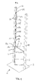
- eine perspektivische Ansicht eines Aufzugs,
- Fig. 2
- eine perspektivische Detailansicht des in
Fig. 1 dargestellten Aufzugs, - Fig. 3
- eine weitere Detailansicht des in
Fig. 1 dargestellten Aufzugs, - Fig. 4
- eine perspektivische Ansicht des in
Fig. 1 dargestellten Aufzugs im vollständig ausgefahrenen Zustand, - Fig. 5
- eine Seitenansicht eines ersten Trägerprofils des in
Fig. 4 dargestellten Aufzugs, - Fig. 6a
- einen Querschnitt durch ein erstes Führungselement,
- Fig. 6b
- einen Querschnitt durch ein viertes Führungselement,
- Fig. 6c
- einen Querschnitt durch ein achtes Führungselement,
- Fig. 7a
- einen Querschnitt durch ein Führungselement,
- Fig. 7b
- einen Querschnitt durch ein Führungselement und einen Teleskopzylinder und
- Fig. 8
- einen Querschnitt durch einen Fußbereichs des Teleskopzylinder.
- Fig. 1
- a perspective view of an elevator,
- Fig. 2
- a detailed perspective view of in
Fig. 1 illustrated elevator, - Fig. 3
- another detail view of the in
Fig. 1 illustrated elevator, - Fig. 4
- a perspective view of the in
Fig. 1 illustrated elevator in the fully extended state, - Fig. 5
- a side view of a first carrier profile of in
Fig. 4 illustrated elevator, - Fig. 6a
- a cross section through a first guide element,
- Fig. 6b
- a cross section through a fourth guide element,
- Fig. 6c
- a cross section through an eighth guide element,
- Fig. 7a
- a cross section through a guide element,
- Fig. 7b
- a cross section through a guide element and a telescopic cylinder and
- Fig. 8
- a cross section through a foot portion of the telescopic cylinder.
Nachfolgend bezeichnen gleiche Bezugszeichen Elemente mit gleichen oder ähnlichen technischen Merkmalen.Hereinafter, like reference numerals designate elements having the same or similar technical features.
Ein Verbindungsbalken 5 ist an einem freien Ende 6 (siehe
Die Vorrichtung 1 umfasst weiter eine erste Führungsvorrichtung 7 und eine weitere Führungsvorrichtung 8. Mittels der ersten Führungsvorrichtung 7 ist eine Bewegung der Teilzylinder 4b, 4c, 4d des ersten Teleskopzylinders 3 in und entgegen einer Hubrichtung des Teleskopzylinders 3 führbar. Die Hubrichtung bezeichnet hierbei eine in einer vertikalen Richtung z orientierte Richtung, wobei die vertikale Richtung z orthogonal zu einer Oberfläche 9 eines Befestigungsbereichs, beispielsweise einer Erdoberfläche, orientiert ist. Die vertikale Richtung z kann insbesondere entgegengesetzt zu einer Richtung einer auf die Kabine 2 wirkenden Gewichtskraft orientiert sein.The device 1 further comprises a
Entsprechend dient die weitere Führungsvorrichtung 8 zur Führung einer Bewegung der beweglichen Teilzylinder des weiteren Teleskopzylinders in und entgegen der Hubrichtung.Accordingly, the
Die erste und die weitere Führungsvorrichtung 7, 8 sind gleichartig ausgebildet. Daher wird im Folgenden nur die erste Führungsvorrichtung 7 näher erläutert.The first and the
Die erste Führungsvorrichtung 7 umfasst ein Trägerprofil 10 und neun Führungselemente 11a, 11b, 11c, 11 d, 11e, 11 f, 11g, 11h, 11i. Die Führungselemente 11a, ..., 11 i werden hierbei von dem Trägerprofil 10 ausgebildet oder sind an diesem befestigt.The
In
Das Trägerprofil 10 ist an der Befestigungsfläche 9 befestigt oder in ein in vertikaler Richtung z unterhalb der Befestigungsfläche 9 angeordnetes Fundament eingebracht. Das gleiche gilt für das Trägerprofil 10 der weiteren Führungsvorrichtung 8.The
Durch ein Ausfahren der Teleskopzylinder 3 kann die Kabine 2 in vertikaler Richtung z, also nach oben, bewegt werden. Während dieser Ausfahrbewegung bewegen sich die beweglichen Teilzylinder 4b, 4d, 4d des ersten Teleskopzylinders 3 nacheinander durch Durchgangsbereiche 13 (siehe z.B.
Im vollständig ausgefahrenen Zustand des ersten Teleskopzylinders 3 erstreckt sich jeder bewegliche Teilzylinder 4b, 4c, 4d durch die vorhergehend erläuterten Durchgangsbereiche 13 mehrerer Führungselemente 11a,..., 11i. Somit dienen die Führungselemente 11a, ..., 11i sowohl einer Führung der Bewegung der beweglichen Teilzylinder 4b, 4c, 4d als auch einer Halterung im ausgefahrenen Zustand des entsprechenden Teilzylinders 4b, 4c, 4d.In the fully extended state of the first
Aus einem vollständig ausgefahrenen Zustand des entsprechenden Teilzylinders 4b, 4c, 4d bewegt sich dieser auch bei einer Einfahrbewegung des ersten Teleskopzylinders 3, also bei einer Bewegung entgegen der Hubrichtung, durch die Durchgangsbereiche 13 der entsprechenden Führungselemente 11a, ..., 11i. Im vollständig eingefahrenen Zustand sind die Durchgangsbereiche 13 der Führungselemente 11 a, ..., 11 i frei.From a fully extended state of the
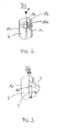
Durch den Durchgangsbereich 13 ist eine in Hubrichtung untere Außenfläche (Unterseite) des Führungselements 11h mit einer in Hubrichtung oberen Außenfläche (Oberseite) des Führungselements 11h verbunden.Through the
Weiter dargestellt ist, dass das Führungselement 11 h eine weitere Öffnung 14 aufweist, die das von dem Durchgangsbereich 13 umfasste Innenvolumen mit einem Außenvolumen des Führungselements 11h verbindet. Die weitere Öffnung 14 kann beispielsweise schlitzförmig ausgebildet sein, wobei der Schlitz sich ebenfalls entlang der vertikalen Richtung z erstreckt. Somit ist der Durchgangsbereich 13 in Hubrichtung nach unten, in Hubrichtung nach oben und zu einer zur Hubrichtung senkrechten Richtung geöffnet bzw. aus diesen Richtungen zugänglich. Hierbei ist das Führungselement 11 h derart in dem Innenvolumen des Trägerprofils 10 angeordnet, dass der Schlitz 12 des Trägerprofils 10 und die weitere Öffnung 14 des Führungselements 11 h zur gleichen Seite hin orientiert sind bzw. auf gleichen Seiten angeordnet sind. Somit ist der Durchgangsbereich 13 durch den Schlitz 12 und die weitere Öffnung 14 zugänglich. Die weitere Öffnung 14 dient zum Durchführen des Verbindungsbalkens 5 (siehe
In
In
Während des Ausfahrens aus einem vollständig eingefahrenen Zustand des ersten Teleskopzylinders 3 durchfährt der zweite Teilzylinder 4b nacheinander Durchgangsbereiche 13 des ersten, des zweiten und des dritten Führungselements 11a, 11 b, 11 c. Hiernach ist der zweite Teilzylinder 4b vollständig ausgefahren. Hiernach durchfährt der dritte Teilzylinder 4c nacheinander die Durchgangsbereiche 13 des vierten, des fünften und des sechsten Führungselements 11d, 11 e, 11 f. Hiernach ist der dritte Teilzylinder 4c vollständig ausgefahren. Hiernach durchfährt der vierte Teilzylinder 4c nacheinander die Durchgangsbereiche des siebten, des achten und des neunten Führungselements 11 g, 11 h, 11 i. Hiernach ist auch der vierte Teilzylinder 4c und somit der gesamte erste Teleskopzylinder 3 vollständig ausgefahren.During extension from a fully retracted state of the first
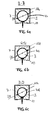
Wie vorhergehend bereits erläutert, sind Durchmesser der Durchgangsbereiche 13 des ersten, des zweiten und des dritten Führungselements 11 a, 11 b, 11 c an einen Außendurchmesser des zweiten Teilzylinders 4b angepasst. Entsprechend sind Durchmesser der Durchgangsbereiche 13 des vierten, des fünften und des sechsten Führungselements 11d, 11d, 11f an einen Außendurchmesser des dritten Teilzylinders 4c angepasst. Somit ist ein Durchmesser der Durchgangsbereiche 13 des vierten, des fünften und des sechsten Führungselements 11 d, 11 e, 11 f kleiner als der Durchmesser der Durchgangsbereiche 13 des ersten, des zweiten und des dritten Führungselements 11 a, 11 b, 11 s. Entsprechend sind die Durchmesser der Durchgangsbereiche 13 des siebten, des achten und des neunten Führungselements 11 g, 11 h, 11 i an einen Außendurchmesser des vierten Teilzylinders 4d angepasst und somit kleiner als der Durchmesser der Durchgangsbereiche 13 des vierten, des fünften und des sechsten Führungselements 11 d, 11 e, 11f. Somit ist ersichtlich, dass die Durchmesser von Durchgangsbereichen 13 der Führungselemente 11a, ..., 11 i in Hubrichtung abnehmen, wobei Durchmesser von Durchgangsbereichen 13 von Führungselementen 11a, ..., 11 i, die eine Bewegung eines bestimmten Teilzylinders 4b, 4c, 4d führen, gleich sind.As already explained above, diameters of the
In
Wie auch in
Dargestellt sind weiter drei Schnittlinien B-B, C-C, D-D, wobei korrespondierende Querschnitte in den
Somit liegt ein Teilabschnitt einer äußeren Oberfläche, insbesondere einer Mantelfläche, des zweiten Teilzylinders 4b an einer von dem ersten Führungselement 11a ausgebildeten Führungsfläche an. Die Führungsfläche des Führungselements 11 a wird hierbei von der die Durchgangsöffnung 13 umfassenden Seitenwand des Führungselements 11 a ausgebildet.Thus, a partial section of an outer surface, in particular a lateral surface, of the second partial cylinder 4b bears against a guide surface formed by the first guide element 11a. The guide surface of the guide member 11 a is in this case formed by the through-opening 13 comprehensive side wall of the guide member 11 a.
In Fig. 7c ist ein Querschnitt D-D (siehe
In
In
Weiter dargestellt ist eine Rückleitung 18, die beispielsweise zu einem nicht dargestellten Hydrauliktank führen kann. Die Rückleitung 18 ist über mehrere Auslassöffnungen 19a, 19b, 19c, 19d, 19e, 19f mit dem Innenvolumen des Teleskopzylinders 3 fluidtechnisch verbunden. Hierbei sind die Auslassöffnungen 19a, ..., 19f in Hubrichtung mit einem vorbestimmten Abstand zueinander beabstandet angeordnet. Eine erste, ein zweite, eine dritte, eine vierte und eine fünfte Auslassöffnung 19a, ..., 19e verbinden hierbei ein Innenvolumen des ersten Teilzylinders 4a mit der Rückleitung 18. Eine sechste Auslassöffnung 19f verbindet ein Innenvolumen des zweiten Teilzylinders 4b mit der Rückleitung 18. In den Auslassöffnungen 19a,..., 19f können Rückschlagventile angeordnet sein oder die Auslassöffnungen 19a, ..., 19f können Rückschlagventile umfassen, die den Fluss des Betriebsmittels von der Rückleitung 18 in das Innenvolumen des Teleskopzylinders 3 verhindern. Beim Einfahren des Teleskopzylinders 3 wird zuerst die sechste Auslassöffnung 19f von der Mantelfläche des dritten Teilzylinders 4c verschlossen. Nachfolgend wird beim Einfahren zuerst die fünfte Auslassöffnung 19e, die vierte Auslassöffnung 19d, die dritte Auslassöffnung 19c, die zweite Auslassöffnung 19b und zuletzt die erste Auslassöffnung 19a jeweils durch die Mantelfläche des zweiten Teilzylinders 4b verschlossen. Somit wird also sequenziell die zum Auslass des Betriebsmittels zur Verfügung stehende Gesamtöffnung beim Einfahren verringert. Hierdurch wird auch die Geschwindigkeit einer Druckreduktion im Teleskopzylinder 3 und somit auch die Einfahrgeschwindigkeit verringert. Verdeckt die Mantelfläche des zweiten Teilzylinders 4b die erste Auslassöffnung 19a, so kann kein Betriebsmittel mehr durch die Rückleitung 18 abgeführt werden. In diesem Fall ist keine Reduktion des durch den Teleskopzylinder 3 erzeugten Druckes, der entgegen der Einfahrbewegung gerichtet ist, mehr möglich. Somit wird auch die Geschwindigkeit der Abwärtsbewegung auf Null reduziert.Also shown is a
Selbstverständlich ist es vorstellbar, weitere Ventile sowohl in der Einlassöffnung 16 als auch in den Auslassöffnungen 19a, ..., 19f vorzusehen, die eine Menge des einströmenden oder ausströmenden Betriebsmittels verändern können.Of course, it is conceivable to provide further valves both in the
- 11
- Vorrichtungcontraption
- 22
- Kabinecabin
- 33
- erster Teleskopzylinderfirst telescopic cylinder
- 4a, 4b, 4c, 4d4a, 4b, 4c, 4d
- Teilzylinderpartial cylinder
- 55
- Verbindungsbalkenconnecting beams
- 66
- freies Endefree end
- 77
- erste Führungsvorrichtungfirst guide device
- 88th
- zweite Führungsvorrichtungsecond guide device
- 99
- Befestigungsflächemounting surface
- 1010
- Trägerprofilcarrier profile
- 11a, ..., 11i11a, ..., 11i
- Führungselementeguide elements
- 1212
- Schlitzslot
- 1313
- DurchgangsbereichPassage area
- 1414
- weitere Öffnungfurther opening
- 1515
- abgeschrägter Endbereichbevelled end area
- 1616
- Einlassöffnunginlet port
- 1717
- Zuleitungsupply
- 1818
- Rückleitungreturn
- 19a, ..., 19f19a, ..., 19f
- Auslassöffnungoutlet
- D1D1
- erster Durchmesserfirst diameter
- D2D2
- zweiter Durchmessersecond diameter
- D3D3
- dritter Durchmesserthird diameter
Claims (14)
wobei
die Führungsvorrichtung (7, 8) oder mindestens ein Führungselement (11a,..., 11 i) der Führungsvorrichtung (7, 8) zur Führung der Bewegung des mindestens einen Teilzylinders (4a, 4b, 4c, 4d) mit zumindest einem Teilabschnitt einer äußeren Oberfläche des mindestens einen Teilzylinders (4a, 4b, 4c, 4d) wechselwirkt, dadurch gekennzeichnet, dass
die Führungsvorrichtung (7, 8) ein Trägerprofil (10) umfasst, wobei das mindestens eine Führungselement (11a, ..., 11i) an dem Trägerprofil (10) befestigt ist oder von dem Trägerprofil (10) ausgebildet wird, wobei die Führungsvorrichtung (7, 8) ortsfest angeordnet ist.Device for moving a transport element of an elevator, the device (1) comprising at least one telescopic cylinder (3), the telescopic cylinder (3) comprising a plurality of partial cylinders (4a, 4b, 4c, 4d), the transport element being provided with a free end (6 ) of the telescopic cylinder (6) is mechanically connectable, wherein the device (1) further comprises at least one guide device (7, 8) for guiding at least one partial cylinder (4a, 4b, 4c, 4d), wherein by means of the guide device (7, 8) a movement of the at least one partial cylinder (4a, 4b, 4c, 4d) can be guided in and against a stroke direction of the telescopic cylinder (3),
in which
the guide device (7, 8) or at least one guide element (11a, ..., 11 i) of the guide device (7, 8) for guiding the movement of the at least one partial cylinder (4a, 4b, 4c, 4d) with at least one section of a outer surface of the at least one partial cylinder (4a, 4b, 4c, 4d) interacts, characterized in that
the guide device (7, 8) comprises a carrier profile (10), wherein the at least one guide element (11a, ..., 11i) is fastened to the carrier profile (10) or is formed by the carrier profile (10). 7, 8) is arranged stationary.
wobei
die Führungsvorrichtung (7, 8) oder mindestens ein Führungselement (11 a, ..., 11 i) der Führungsvorrichtung (7, 8) zur Führung der Bewegung des mindestens einen Teilzylinders (4a, 4b, 4c, 4d) mit zumindest einem Teilabschnitt einer äußeren Oberfläche des mindestens einen Teilzylinders (4a, 4b, 4c, 4d) wechselwirkt, dadurch gekennzeichnet, dass
die Führungsvorrichtung (7, 8) ein Trägerprofil (10) umfasst, wobei das mindestens eine Führungselement (11a, ..., 11 i) an dem Trägerprofil (10) befestigt ist oder von dem Trägerprofil (10) ausgebildet wird, wobei die Führungsvorrichtung (7, 8) ortsfest angeordnet ist.Method for moving a transport element of an elevator, wherein a device (1) for moving the transport element comprises at least one telescopic cylinder (3), wherein the telescopic cylinder (3) comprises a plurality of partial cylinders (4a, 4b, 4c, 4d), wherein the transport element with a free end (6) of the Telescope cylinder (3) is mechanically connected, wherein the device (1) further comprises at least one guide device (7, 8) for guiding at least one partial cylinder (4a, 4b, 4c, 4d), wherein by means of the guide device (7, 8) a movement the at least one partial cylinder (4a, 4b, 4c, 4d) is guided in and counter to a stroke direction of the telescopic cylinder (3),
in which
the guide device (7, 8) or at least one guide element (11 a, ..., 11 i) of the guide device (7, 8) for guiding the movement of the at least one partial cylinder (4a, 4b, 4c, 4d) with at least one subsection an outer surface of the at least one partial cylinder (4a, 4b, 4c, 4d) interacts, characterized in that
the guide device (7, 8) comprises a carrier profile (10), wherein the at least one guide element (11a, ..., 11 i) is fastened to the carrier profile (10) or is formed by the carrier profile (10), wherein the guiding device (7, 8) is arranged stationary.
Applications Claiming Priority (1)
| Application Number | Priority Date | Filing Date | Title |
|---|---|---|---|
| DE201310221211 DE102013221211A1 (en) | 2013-10-18 | 2013-10-18 | Device and method for moving a transport element of a load or passenger elevator |
Publications (2)
| Publication Number | Publication Date |
|---|---|
| EP2862830A1 true EP2862830A1 (en) | 2015-04-22 |
| EP2862830B1 EP2862830B1 (en) | 2016-03-30 |
Family
ID=51730406
Family Applications (1)
| Application Number | Title | Priority Date | Filing Date |
|---|---|---|---|
| EP14189301.6A Active EP2862830B1 (en) | 2013-10-18 | 2014-10-17 | Device and method for moving a transport element of a freight or passenger elevator |
Country Status (4)
| Country | Link |
|---|---|
| EP (1) | EP2862830B1 (en) |
| DE (1) | DE102013221211A1 (en) |
| ES (1) | ES2574533T3 (en) |
| PL (1) | PL2862830T3 (en) |
Families Citing this family (1)
| Publication number | Priority date | Publication date | Assignee | Title |
|---|---|---|---|---|
| DE202018106626U1 (en) * | 2018-11-21 | 2020-02-26 | Telejet Kommunikations Gmbh | Floor elevator |
Citations (8)
| Publication number | Priority date | Publication date | Assignee | Title |
|---|---|---|---|---|
| US3968860A (en) * | 1974-10-25 | 1976-07-13 | Dover Corporation | Hydraulic elevator installation |
| US4155425A (en) * | 1977-08-16 | 1979-05-22 | A. S. K. Elevator Service, Inc. | Stabilized hydraulic elevator |
| US4667775A (en) * | 1986-04-30 | 1987-05-26 | Westinghouse Electric Corp. | Hydraulic elevator system |
| US4683988A (en) * | 1985-09-27 | 1987-08-04 | Shrum Jr William M | Multi-stage hydraulic drive system |
| US6431322B1 (en) * | 2000-07-31 | 2002-08-13 | Inventio Ag | Plunger guide for a telescopic jack in a hydraulic elevator |
| WO2003100197A1 (en) * | 2002-05-29 | 2003-12-04 | Ez Indus Co., Ltd. | Apparatus for driving raising and lowering of lift for tower type storehouse |
| EP2428482A1 (en) | 2010-09-14 | 2012-03-14 | Otto Nussbaum GmbH & Co. KG | Lifting platform for motor vehicles |
| CN102491224A (en) | 2011-12-26 | 2012-06-13 | 济南华北升降平台制造有限公司 | Telescopic cylindrical lift |
Family Cites Families (4)
| Publication number | Priority date | Publication date | Assignee | Title |
|---|---|---|---|---|
| US3650356A (en) * | 1969-12-18 | 1972-03-21 | Rchard L Brown | Hydraulically-actuatable elevator system |
| DE2029367A1 (en) * | 1970-06-15 | 1971-12-23 | Klingenburg O | Hydraulic elevator |
| GB1496878A (en) * | 1973-11-01 | 1978-01-05 | Becker Equipment & Lifts Ltd | Hydraulic lift mechanism |
| IT1278585B1 (en) * | 1994-05-25 | 1997-11-24 | O R E M Spa | STEM TRAVELING DUPLICATOR. |
-
2013
- 2013-10-18 DE DE201310221211 patent/DE102013221211A1/en not_active Ceased
-
2014
- 2014-10-17 ES ES14189301.6T patent/ES2574533T3/en active Active
- 2014-10-17 EP EP14189301.6A patent/EP2862830B1/en active Active
- 2014-10-17 PL PL14189301.6T patent/PL2862830T3/en unknown
Patent Citations (8)
| Publication number | Priority date | Publication date | Assignee | Title |
|---|---|---|---|---|
| US3968860A (en) * | 1974-10-25 | 1976-07-13 | Dover Corporation | Hydraulic elevator installation |
| US4155425A (en) * | 1977-08-16 | 1979-05-22 | A. S. K. Elevator Service, Inc. | Stabilized hydraulic elevator |
| US4683988A (en) * | 1985-09-27 | 1987-08-04 | Shrum Jr William M | Multi-stage hydraulic drive system |
| US4667775A (en) * | 1986-04-30 | 1987-05-26 | Westinghouse Electric Corp. | Hydraulic elevator system |
| US6431322B1 (en) * | 2000-07-31 | 2002-08-13 | Inventio Ag | Plunger guide for a telescopic jack in a hydraulic elevator |
| WO2003100197A1 (en) * | 2002-05-29 | 2003-12-04 | Ez Indus Co., Ltd. | Apparatus for driving raising and lowering of lift for tower type storehouse |
| EP2428482A1 (en) | 2010-09-14 | 2012-03-14 | Otto Nussbaum GmbH & Co. KG | Lifting platform for motor vehicles |
| CN102491224A (en) | 2011-12-26 | 2012-06-13 | 济南华北升降平台制造有限公司 | Telescopic cylindrical lift |
Also Published As
| Publication number | Publication date |
|---|---|
| DE102013221211A1 (en) | 2015-04-23 |
| PL2862830T3 (en) | 2016-09-30 |
| ES2574533T3 (en) | 2016-06-20 |
| EP2862830B1 (en) | 2016-03-30 |
Similar Documents
| Publication | Publication Date | Title |
|---|---|---|
| EP0983897B1 (en) | Lifting apparatus | |
| WO2016096694A1 (en) | Elevator having a movable machine room | |
| EP1840068A1 (en) | Elevator system comprising an elevator car brake device and method for braking an elevator car | |
| EP2346771B1 (en) | Modernisation method for lift systems | |
| DE102013107305A1 (en) | Lifting device and lift with such a lifting device | |
| EP3470355A1 (en) | Buffer device for a cabin of a lift facility and arrangement of the buffer device and lift facility | |
| EP0254840B1 (en) | Method and device for lifting and lowering a load by a hydraulic linear motor | |
| EP2862830B1 (en) | Device and method for moving a transport element of a freight or passenger elevator | |
| EP2614028B1 (en) | Device for mounting a load-bearing fork profile | |
| AT513614B1 (en) | Ladder set, especially fire chief, as well as equipped vehicle | |
| AT513612B1 (en) | Ladder set, especially fire chief, as well as equipped vehicle | |
| DE202018004562U1 (en) | Device for limiting the travel of a car and / or a counterweight of an elevator system with a guide rail | |
| EP1034996B1 (en) | Departure and arrival station for an aerial cableway with two cables and a cabin for the transport of passengers who board and alight at such a station | |
| EP3924284B1 (en) | Elevator system | |
| DE102015112086B4 (en) | DEVICE FOR ADJUSTING A STEERING COLUMN OF A MOTOR VEHICLE AND STEERING SYSTEM | |
| EP1293471B1 (en) | Telescopic boom | |
| EP3645913B1 (en) | Arrangement with two energy guide chains and adjustable fixed point | |
| EP3438002A1 (en) | Lifting vehicle for transporting persons in the airport area | |
| EP1479636A1 (en) | Buffer that can create a safety inspection zone for elevators | |
| DE4304553C2 (en) | Lifting platform, in particular motor vehicle lifting platform | |
| DE202015101275U1 (en) | Niveauerzwingungseinrichtung | |
| EP1316448A2 (en) | Height adjustable support system and method for vehicle leveling by using the support system | |
| WO2012152253A1 (en) | Hydraulic cylinder (lift cylinder) for vehicle lifts | |
| EP2743226A1 (en) | Door for a lift system | |
| DE102017110275A1 (en) | Elevator system with two shafts |
Legal Events
| Date | Code | Title | Description |
|---|---|---|---|
| PUAI | Public reference made under article 153(3) epc to a published international application that has entered the european phase |
Free format text: ORIGINAL CODE: 0009012 |
|
| 17P | Request for examination filed |
Effective date: 20141017 |
|
| AK | Designated contracting states |
Kind code of ref document: A1 Designated state(s): AL AT BE BG CH CY CZ DE DK EE ES FI FR GB GR HR HU IE IS IT LI LT LU LV MC MK MT NL NO PL PT RO RS SE SI SK SM TR |
|
| AX | Request for extension of the european patent |
Extension state: BA ME |
|
| R17P | Request for examination filed (corrected) |
Effective date: 20150320 |
|
| RBV | Designated contracting states (corrected) |
Designated state(s): AL AT BE BG CH CY CZ DE DK EE ES FI FR GB GR HR HU IE IS IT LI LT LU LV MC MK MT NL NO PL PT RO RS SE SI SK SM TR |
|
| GRAP | Despatch of communication of intention to grant a patent |
Free format text: ORIGINAL CODE: EPIDOSNIGR1 |
|
| INTG | Intention to grant announced |
Effective date: 20151112 |
|
| GRAS | Grant fee paid |
Free format text: ORIGINAL CODE: EPIDOSNIGR3 |
|
| GRAA | (expected) grant |
Free format text: ORIGINAL CODE: 0009210 |
|
| AK | Designated contracting states |
Kind code of ref document: B1 Designated state(s): AL AT BE BG CH CY CZ DE DK EE ES FI FR GB GR HR HU IE IS IT LI LT LU LV MC MK MT NL NO PL PT RO RS SE SI SK SM TR |
|
| REG | Reference to a national code |
Ref country code: GB Ref legal event code: FG4D Free format text: NOT ENGLISH |
|
| REG | Reference to a national code |
Ref country code: CH Ref legal event code: EP |
|
| REG | Reference to a national code |
Ref country code: AT Ref legal event code: REF Ref document number: 785148 Country of ref document: AT Kind code of ref document: T Effective date: 20160415 |
|
| REG | Reference to a national code |
Ref country code: IE Ref legal event code: FG4D Free format text: LANGUAGE OF EP DOCUMENT: GERMAN |
|
| REG | Reference to a national code |
Ref country code: DE Ref legal event code: R096 Ref document number: 502014000533 Country of ref document: DE |
|
| REG | Reference to a national code |
Ref country code: NL Ref legal event code: FP |
|
| REG | Reference to a national code |
Ref country code: ES Ref legal event code: FG2A Ref document number: 2574533 Country of ref document: ES Kind code of ref document: T3 Effective date: 20160620 |
|
| REG | Reference to a national code |
Ref country code: LT Ref legal event code: MG4D |
|
| PG25 | Lapsed in a contracting state [announced via postgrant information from national office to epo] |
Ref country code: NO Free format text: LAPSE BECAUSE OF FAILURE TO SUBMIT A TRANSLATION OF THE DESCRIPTION OR TO PAY THE FEE WITHIN THE PRESCRIBED TIME-LIMIT Effective date: 20160630 Ref country code: GR Free format text: LAPSE BECAUSE OF FAILURE TO SUBMIT A TRANSLATION OF THE DESCRIPTION OR TO PAY THE FEE WITHIN THE PRESCRIBED TIME-LIMIT Effective date: 20160701 Ref country code: FI Free format text: LAPSE BECAUSE OF FAILURE TO SUBMIT A TRANSLATION OF THE DESCRIPTION OR TO PAY THE FEE WITHIN THE PRESCRIBED TIME-LIMIT Effective date: 20160330 Ref country code: HR Free format text: LAPSE BECAUSE OF FAILURE TO SUBMIT A TRANSLATION OF THE DESCRIPTION OR TO PAY THE FEE WITHIN THE PRESCRIBED TIME-LIMIT Effective date: 20160330 |
|
| PG25 | Lapsed in a contracting state [announced via postgrant information from national office to epo] |
Ref country code: LV Free format text: LAPSE BECAUSE OF FAILURE TO SUBMIT A TRANSLATION OF THE DESCRIPTION OR TO PAY THE FEE WITHIN THE PRESCRIBED TIME-LIMIT Effective date: 20160330 Ref country code: SE Free format text: LAPSE BECAUSE OF FAILURE TO SUBMIT A TRANSLATION OF THE DESCRIPTION OR TO PAY THE FEE WITHIN THE PRESCRIBED TIME-LIMIT Effective date: 20160330 Ref country code: LT Free format text: LAPSE BECAUSE OF FAILURE TO SUBMIT A TRANSLATION OF THE DESCRIPTION OR TO PAY THE FEE WITHIN THE PRESCRIBED TIME-LIMIT Effective date: 20160330 Ref country code: RS Free format text: LAPSE BECAUSE OF FAILURE TO SUBMIT A TRANSLATION OF THE DESCRIPTION OR TO PAY THE FEE WITHIN THE PRESCRIBED TIME-LIMIT Effective date: 20160330 |
|
| REG | Reference to a national code |
Ref country code: FR Ref legal event code: PLFP Year of fee payment: 3 |
|
| PG25 | Lapsed in a contracting state [announced via postgrant information from national office to epo] |
Ref country code: EE Free format text: LAPSE BECAUSE OF FAILURE TO SUBMIT A TRANSLATION OF THE DESCRIPTION OR TO PAY THE FEE WITHIN THE PRESCRIBED TIME-LIMIT Effective date: 20160330 Ref country code: IS Free format text: LAPSE BECAUSE OF FAILURE TO SUBMIT A TRANSLATION OF THE DESCRIPTION OR TO PAY THE FEE WITHIN THE PRESCRIBED TIME-LIMIT Effective date: 20160730 |
|
| PG25 | Lapsed in a contracting state [announced via postgrant information from national office to epo] |
Ref country code: RO Free format text: LAPSE BECAUSE OF FAILURE TO SUBMIT A TRANSLATION OF THE DESCRIPTION OR TO PAY THE FEE WITHIN THE PRESCRIBED TIME-LIMIT Effective date: 20160330 Ref country code: CZ Free format text: LAPSE BECAUSE OF FAILURE TO SUBMIT A TRANSLATION OF THE DESCRIPTION OR TO PAY THE FEE WITHIN THE PRESCRIBED TIME-LIMIT Effective date: 20160330 Ref country code: PT Free format text: LAPSE BECAUSE OF FAILURE TO SUBMIT A TRANSLATION OF THE DESCRIPTION OR TO PAY THE FEE WITHIN THE PRESCRIBED TIME-LIMIT Effective date: 20160801 Ref country code: SK Free format text: LAPSE BECAUSE OF FAILURE TO SUBMIT A TRANSLATION OF THE DESCRIPTION OR TO PAY THE FEE WITHIN THE PRESCRIBED TIME-LIMIT Effective date: 20160330 Ref country code: SM Free format text: LAPSE BECAUSE OF FAILURE TO SUBMIT A TRANSLATION OF THE DESCRIPTION OR TO PAY THE FEE WITHIN THE PRESCRIBED TIME-LIMIT Effective date: 20160330 |
|
| REG | Reference to a national code |
Ref country code: DE Ref legal event code: R097 Ref document number: 502014000533 Country of ref document: DE |
|
| PG25 | Lapsed in a contracting state [announced via postgrant information from national office to epo] |
Ref country code: DK Free format text: LAPSE BECAUSE OF FAILURE TO SUBMIT A TRANSLATION OF THE DESCRIPTION OR TO PAY THE FEE WITHIN THE PRESCRIBED TIME-LIMIT Effective date: 20160330 |
|
| PLBE | No opposition filed within time limit |
Free format text: ORIGINAL CODE: 0009261 |
|
| STAA | Information on the status of an ep patent application or granted ep patent |
Free format text: STATUS: NO OPPOSITION FILED WITHIN TIME LIMIT |
|
| PG25 | Lapsed in a contracting state [announced via postgrant information from national office to epo] |
Ref country code: BE Free format text: LAPSE BECAUSE OF NON-PAYMENT OF DUE FEES Effective date: 20161031 |
|
| 26N | No opposition filed |
Effective date: 20170103 |
|
| PG25 | Lapsed in a contracting state [announced via postgrant information from national office to epo] |
Ref country code: SI Free format text: LAPSE BECAUSE OF FAILURE TO SUBMIT A TRANSLATION OF THE DESCRIPTION OR TO PAY THE FEE WITHIN THE PRESCRIBED TIME-LIMIT Effective date: 20160330 |
|
| REG | Reference to a national code |
Ref country code: IE Ref legal event code: MM4A |
|
| PG25 | Lapsed in a contracting state [announced via postgrant information from national office to epo] |
Ref country code: LU Free format text: LAPSE BECAUSE OF NON-PAYMENT OF DUE FEES Effective date: 20161017 |
|
| REG | Reference to a national code |
Ref country code: FR Ref legal event code: PLFP Year of fee payment: 4 |
|
| PG25 | Lapsed in a contracting state [announced via postgrant information from national office to epo] |
Ref country code: IE Free format text: LAPSE BECAUSE OF NON-PAYMENT OF DUE FEES Effective date: 20161017 |
|
| REG | Reference to a national code |
Ref country code: BE Ref legal event code: MM Effective date: 20161031 |
|
| PG25 | Lapsed in a contracting state [announced via postgrant information from national office to epo] |
Ref country code: HU Free format text: LAPSE BECAUSE OF FAILURE TO SUBMIT A TRANSLATION OF THE DESCRIPTION OR TO PAY THE FEE WITHIN THE PRESCRIBED TIME-LIMIT; INVALID AB INITIO Effective date: 20141017 |
|
| PG25 | Lapsed in a contracting state [announced via postgrant information from national office to epo] |
Ref country code: MK Free format text: LAPSE BECAUSE OF FAILURE TO SUBMIT A TRANSLATION OF THE DESCRIPTION OR TO PAY THE FEE WITHIN THE PRESCRIBED TIME-LIMIT Effective date: 20160330 Ref country code: CY Free format text: LAPSE BECAUSE OF FAILURE TO SUBMIT A TRANSLATION OF THE DESCRIPTION OR TO PAY THE FEE WITHIN THE PRESCRIBED TIME-LIMIT Effective date: 20160330 Ref country code: MT Free format text: LAPSE BECAUSE OF FAILURE TO SUBMIT A TRANSLATION OF THE DESCRIPTION OR TO PAY THE FEE WITHIN THE PRESCRIBED TIME-LIMIT Effective date: 20160330 Ref country code: MC Free format text: LAPSE BECAUSE OF FAILURE TO SUBMIT A TRANSLATION OF THE DESCRIPTION OR TO PAY THE FEE WITHIN THE PRESCRIBED TIME-LIMIT Effective date: 20160330 |
|
| PG25 | Lapsed in a contracting state [announced via postgrant information from national office to epo] |
Ref country code: BG Free format text: LAPSE BECAUSE OF FAILURE TO SUBMIT A TRANSLATION OF THE DESCRIPTION OR TO PAY THE FEE WITHIN THE PRESCRIBED TIME-LIMIT Effective date: 20160330 |
|
| REG | Reference to a national code |
Ref country code: FR Ref legal event code: PLFP Year of fee payment: 5 |
|
| PG25 | Lapsed in a contracting state [announced via postgrant information from national office to epo] |
Ref country code: AL Free format text: LAPSE BECAUSE OF FAILURE TO SUBMIT A TRANSLATION OF THE DESCRIPTION OR TO PAY THE FEE WITHIN THE PRESCRIBED TIME-LIMIT Effective date: 20160330 |
|
| PGFP | Annual fee paid to national office [announced via postgrant information from national office to epo] |
Ref country code: NL Payment date: 20191021 Year of fee payment: 6 |
|
| PGFP | Annual fee paid to national office [announced via postgrant information from national office to epo] |
Ref country code: PL Payment date: 20191004 Year of fee payment: 6 |
|
| PGFP | Annual fee paid to national office [announced via postgrant information from national office to epo] |
Ref country code: CH Payment date: 20191021 Year of fee payment: 6 Ref country code: TR Payment date: 20191014 Year of fee payment: 6 |
|
| REG | Reference to a national code |
Ref country code: CH Ref legal event code: PL |
|
| REG | Reference to a national code |
Ref country code: NL Ref legal event code: MM Effective date: 20201101 |
|
| PG25 | Lapsed in a contracting state [announced via postgrant information from national office to epo] |
Ref country code: NL Free format text: LAPSE BECAUSE OF NON-PAYMENT OF DUE FEES Effective date: 20201101 |
|
| PG25 | Lapsed in a contracting state [announced via postgrant information from national office to epo] |
Ref country code: LI Free format text: LAPSE BECAUSE OF NON-PAYMENT OF DUE FEES Effective date: 20201031 Ref country code: CH Free format text: LAPSE BECAUSE OF NON-PAYMENT OF DUE FEES Effective date: 20201031 |
|
| PG25 | Lapsed in a contracting state [announced via postgrant information from national office to epo] |
Ref country code: TR Free format text: LAPSE BECAUSE OF NON-PAYMENT OF DUE FEES Effective date: 20201017 |
|
| PG25 | Lapsed in a contracting state [announced via postgrant information from national office to epo] |
Ref country code: PL Free format text: LAPSE BECAUSE OF NON-PAYMENT OF DUE FEES Effective date: 20201017 |
|
| PGFP | Annual fee paid to national office [announced via postgrant information from national office to epo] |
Ref country code: GB Payment date: 20231020 Year of fee payment: 10 |
|
| PGFP | Annual fee paid to national office [announced via postgrant information from national office to epo] |
Ref country code: ES Payment date: 20231227 Year of fee payment: 10 |
|
| PGFP | Annual fee paid to national office [announced via postgrant information from national office to epo] |
Ref country code: IT Payment date: 20231026 Year of fee payment: 10 Ref country code: FR Payment date: 20231025 Year of fee payment: 10 Ref country code: DE Payment date: 20231020 Year of fee payment: 10 Ref country code: AT Payment date: 20231020 Year of fee payment: 10 |