EP2862322B1 - Communication system, control apparatus, communication method, control method and program - Google Patents
Communication system, control apparatus, communication method, control method and program Download PDFInfo
- Publication number
- EP2862322B1 EP2862322B1 EP13803867.4A EP13803867A EP2862322B1 EP 2862322 B1 EP2862322 B1 EP 2862322B1 EP 13803867 A EP13803867 A EP 13803867A EP 2862322 B1 EP2862322 B1 EP 2862322B1
- Authority
- EP
- European Patent Office
- Prior art keywords
- packet
- control apparatus
- control
- packet processing
- database
- Prior art date
- Legal status (The legal status is an assumption and is not a legal conclusion. Google has not performed a legal analysis and makes no representation as to the accuracy of the status listed.)
- Active
Links
Images


Classifications
-
- H—ELECTRICITY
- H04—ELECTRIC COMMUNICATION TECHNIQUE
- H04L—TRANSMISSION OF DIGITAL INFORMATION, e.g. TELEGRAPHIC COMMUNICATION
- H04L12/00—Data switching networks
-
- H—ELECTRICITY
- H04—ELECTRIC COMMUNICATION TECHNIQUE
- H04L—TRANSMISSION OF DIGITAL INFORMATION, e.g. TELEGRAPHIC COMMUNICATION
- H04L45/00—Routing or path finding of packets in data switching networks
- H04L45/38—Flow based routing
-
- H—ELECTRICITY
- H04—ELECTRIC COMMUNICATION TECHNIQUE
- H04L—TRANSMISSION OF DIGITAL INFORMATION, e.g. TELEGRAPHIC COMMUNICATION
- H04L45/00—Routing or path finding of packets in data switching networks
- H04L45/42—Centralised routing
-
- H—ELECTRICITY
- H04—ELECTRIC COMMUNICATION TECHNIQUE
- H04L—TRANSMISSION OF DIGITAL INFORMATION, e.g. TELEGRAPHIC COMMUNICATION
- H04L45/00—Routing or path finding of packets in data switching networks
- H04L45/58—Association of routers
- H04L45/586—Association of routers of virtual routers
-
- H—ELECTRICITY
- H04—ELECTRIC COMMUNICATION TECHNIQUE
- H04L—TRANSMISSION OF DIGITAL INFORMATION, e.g. TELEGRAPHIC COMMUNICATION
- H04L45/00—Routing or path finding of packets in data switching networks
- H04L45/64—Routing or path finding of packets in data switching networks using an overlay routing layer
-
- H—ELECTRICITY
- H04—ELECTRIC COMMUNICATION TECHNIQUE
- H04L—TRANSMISSION OF DIGITAL INFORMATION, e.g. TELEGRAPHIC COMMUNICATION
- H04L47/00—Traffic control in data switching networks
- H04L47/10—Flow control; Congestion control
Definitions
- the present invention relates to a communication system, a control apparatus, a communication method, a control method and program, and relates to a communication system, a control apparatus, a communication method, a control method and program that process packets in accordance with control by the control apparatus.
- a control apparatus When a control apparatus performs centralized control of a plurality of communication equipment (switches, routers, or the like) as in WO2008/095010 , there may be an increase in load on the control apparatus.
- a load increase on the control apparatus may cause a deterioration in performance in a communication system.
- TEEMU KOPONEN ET AL "Onix: A Distributed Control Platform for Large-scale Production Networks", USENIX, 23 September 2010 (2010-09-23), pages 1-14 , XP061010918 shows a system with a plurality of control apparatuses that determine a packet handling operation. It includes database which stores information relating to the packet handling operation wherein each of the control apparatuses can refer to the database to determine packet handling operation.
- a communication system comprising: a plurality of control apparatuses that determine a packet handling operation (packet processing rule); a plurality of packet processing means that process a packet in accordance with the packet handling operation notified by the control apparatus; assignment means that assigns, with respect to each of the plurality of packet processing means, a control apparatus that controls the packet processing means concerned; and a database that is shared by the plurality of control apparatuses and that stores information related to the packet handling operation; wherein each of the control apparatuses refers to the database to determine the packet handling operation.
- packet processing rule packet processing rule
- packet processing means that process a packet in accordance with the packet handling operation notified by the control apparatus
- assignment means that assigns, with respect to each of the plurality of packet processing means, a control apparatus that controls the packet processing means concerned
- a database that is shared by the plurality of control apparatuses and that stores information related to the packet handling operation; wherein each of the control apparatuses refers to the database to determine the packet handling operation.
- a control apparatus which controls packet processing, comprising: first means that refers to a database shared by the control apparatus and another control apparatus, and determines a packet handling operation related to a processing method for the packet; and second means that notifies the determined packet handling operation to, among a plurality of packet processing means, a packet processing means assigned to the control apparatus.
- a communication method by which a plurality of control apparatuses control packet processing, comprising: assigning, to each of a plurality of packet processing means, a control apparatus that controls the packet processing means concerned; determining, by each of the control apparatuses, a packet handling operation for processing a packet, by referring to a database shared by the plurality of control apparatuses; and notifying, by each of the control apparatuses, the determined packet handling operation to the assigned packet processing means.
- a control method for a control apparatus that controls processing of a packet, comprising: determining a packet handling operation related to a method of processing the packet, by referring to a database shared by the control apparatus and another control apparatus; and notifying the determined packet handling operation to, among a plurality of packet processing means, a packet processing means assigned to the control apparatus.
- a program that executes, in a control apparatus that controls processing of a packet, a process of determining a packet handling operation related to a method of processing the packet, by referring to a database shared by the control apparatus and another control apparatus; and a process of notifying the determined packet handling operation to, among a plurality of packet processing means, a packet processing means assigned to the control apparatus.
- This program can be recorded in a computer-readable storage medium which may be non-transitory. That is, the present disclosure may be embodied as a computer program product.
- the present invention contributes to distribution of load on a control apparatus and of facilitating operation management of a plurality of control apparatuses.
- the present invention is defined in the independent claims.
- the dependent claims define particular embodiments of the invention.
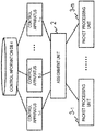
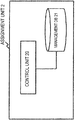
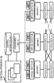
- FIG. 1 shows a configuration example of a communication system of a first exemplary embodiment.
- FIG. 1 is an example, and the configuration of the communication system of the present disclosure is not limited to FIG. 1 .
- the communication system includes a plurality of control apparatuses 1, an assignment unit 2, a plurality of packet processing units 3, and a control information DB (Database) 4.
- the respective control apparatuses 1 share the control information DB 4, and refer to the control information DB 4 to control the packet processing units 3. Since the respective control apparatuses 1 share the database, the respective control apparatuses 1 need not store control information for controlling the packet processing units. Accordingly, in a case of switching a packet processing unit that is a target for control, or a case of replacing a control apparatus 1 in which a failure has occurred, the respective control apparatuses 1 need not execute processing such as handing over control information among the control apparatuses, and operation management of the control apparatuses is facilitated.
- the respective packet processing units 3 process packets in accordance with a packet handling operation (i.e. packet processing rule) notified by a control apparatus 1.
- a packet processing unit 3 executes processing such as packet forwarding, packet header rewriting, and packet dropping, in accordance with a packet handling operation notified by the control apparatus 1.
- the packet processing unit 3 is, for example, communication equipment such as a switch, a router, or the like.
- functionality equivalent to communication equipment such as a switch, a router, or the like may be configured by software (virtual switch).
- FIG. 2 shows an example of a packet handling operation notified by the control apparatus 1 to the packet processing unit 3.
- control apparatus 1 transmits to the packet processing unit a packet handling operation including a packet processing method and a condition (matching rule) for identifying a packet that is a target of the processing method.
- the matching rule for example, is a rule identified based on information included in the packet, such as a packet to be transmitted to a prescribed destination or a packet transmitted from a prescribed transmission source.
- the packet processing unit 3 processes a packet conforming with a matching rule in accordance with a processing method corresponding to the matching rule.
- the assignment unit 2 assigns, with regard to each of the packet processing units 3, a control apparatus 1 that controls a relevant packet processing unit 3.
- the assignment unit 2 for example, assigns the control apparatus 1-1 to the packet processing unit 3-1, as in the example of FIG. 3 . It is to be noted that the assignment unit 2 manages the control apparatuses 1 and the packet processing units 3 present in the system.
- the assignment unit 2 may determine a control apparatus 1 to be assigned to a packet processing unit 3 every time a packet handling operation enquiry is transmitted from the packet processing unit 3. Furthermore, the assignment unit 2 may determine a packet processing unit 3 corresponding to a control apparatus 1 that has transmitted a packet handling operation every time the control apparatus 1 transmits the packet handling operation to the packet processing unit. That is, the assignment unit 2 may assign the control apparatuses to the respective packet processing units 3 at an arbitrary trigger.
- the assignment unit 2 may select a plurality of packet processing units 3 corresponding to a control apparatus 1.
- the packet processing units 3 process packets in accordance with an instruction notified by the control apparatus 1 assigned by the assignment unit 2. That is, the control apparatus 1 may control only the packet processing unit 3 assigned by the assignment unit 2. It is to be noted that the assignment unit 2 may assign a plurality of the packet processing units 3 to the control apparatus 1.
- the assignment unit 2 for example, assigns a corresponding control apparatus 1 to the respective packet processing units 3, based on identification information (for example, IP address, Datapath ID, or the like) of the packet processing units 3.
- the assignment unit 2 for example, assigns control apparatuses 1 so that load is distributed among each of the control apparatuses 1. For example, the assignment unit 2 allocates the control apparatuses 1 to the packet processing units 3, in a round robin manner.
- the control information DB 4 manages information related to packet handling operations notified to the assigned packet processing units 3 by the respective control apparatuses 1. It is to be noted that the control information DB 4 is configured by a plurality of databases, and the plurality of databases may be shared by the respective control apparatuses 1. By the configuration of a plurality of databases, the control information DB 4 has redundancy.
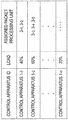
- FIG. 4 shows an example of information stored by the control information DB 4.
- FIG. 4 is an example, and the information stored by the control information DB 4 is not limited to FIG. 4 .
- the control information DB 4 for example, manages candidate packet handling operations to be notified to the packet processing units 3. Furthermore, the control information DB 4, for example, may manage information (control policy or the like) used for generating a packet handling operation by a control apparatus 1.
- the control information DB 4 manages candidate packet handling operations to be notified to the packet processing units 3.
- the respective packet handling operations include a matching rule and a processing method.
- the packet processing units 3 process packets in accordance with a processing method specified in the packet handling operation.
- the packet processing unit 3 compares a matching rule and a received packet. In a case where the received packet matches the matching rule, the packet processing unit 3 processes the received packet by a processing method corresponding to the matching rule.
- the matching rule for example, is a condition for identifying a packet as a communication flow.
- a communication flow is a sequence of packets identified by a prescribed condition.
- the matching rule for example, is a rule identified based on information included in a packet, such as a packet to be transmitted to a prescribed destination or a packet transmitted from a prescribed transmission source.
- the respective control apparatuses 1 refer to the control information DB 4 to determine a packet handling operation to be notified to the assigned packet processing unit 3.
- the respective control apparatuses 1 may update content of the control information DB 4.
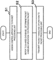
- FIG. 5 is a flowchart showing an operational example of the first exemplary embodiment.
- the assignment unit 2 assigns a control apparatus 1 to a packet processing unit 3 (S1).
- the control apparatus 1 refers to the control information DB 4 shared by the plurality of control apparatuses to determine a packet handling operation for notification to an assigned packet processing unit 3 (S2).
- the control apparatus 1 transmits a determined packet handling operation to the packet processing unit 3 (S3).
- the packet processing unit 3 processes a packet in accordance with the packet handling operation notified by the assigned control apparatus 1.
- control apparatus 1 In a case where a failure occurs in a control apparatus 1, another control apparatus 1, for example, operates in place of the control apparatus 1 in which the failure has occurred. In this case, this control apparatus 1 can operate in place of the control apparatus 1 in which the failure has occurred by only referring to the shared control information DB 4, and the control apparatus 1 need not consider an operation such as handing over information from the control apparatus 1 in which the failure has occurred. Accordingly, in the present exemplary embodiment, a system failure can be easily avoided.
- a configuration example of a communication system in a second exemplary embodiment is similar to FIG. 1 .
- FIG. 6 shows a configuration example of an assignment unit 2 with regard to the second exemplary embodiment.
- the assignment unit 2 assigns a control apparatus 1 to a packet processing unit 3.
- the assignment unit 2 includes a control unit 20 and a management DB (Database) 21.
- the control unit 20 refers to the management DB 21 to determine the control apparatus 1 to be assigned to the packet processing unit 3.
- FIG. 7 shows an example of a database possessed by the management DB 21.
- a configuration of the database possessed by the management DB 21 is not limited to FIG. 7 .
- the control unit 20 gives consideration to the load of each of the control apparatuses 1, to assign a control apparatus 1 to a packet processing unit 3.
- the management DB 21 may manage an operation status of each control apparatus (for example, status indicating that a control apparatus is operating or is stopped).
- the control unit 20 refers to the management DB 21 at communication system startup or when a new packet processing unit 3 is added to the communication system, and performs assignment of the control apparatus 1.
- the control unit 20 may change the assignment of the control apparatuses 1 with respect to the packet processing units 3, for the entire communication system.
- the control unit 20 may refer to the management DB 21 to monitor the load situation of each control apparatus 1, and dynamically change the assignment of the control apparatuses 1 with respect to the packet processing units 3.
- the control unit 20, for example, dynamically changes the assignment for the packet processing units 3, so that the load on the respective control apparatuses 1 approaches the average load of the control apparatuses 1 of the entire system. For example, in a case where the load on a certain control apparatus 1 becomes higher than the average load of the respective control apparatuses by at least a prescribed threshold, the control unit 20 changes the assignment of the packet processing units 3. Furthermore, for example, in a case where the load on a certain control apparatus 1 becomes lower than the average load of the respective control apparatuses by at least a prescribed threshold, the control unit 20 changes the assignment of the packet processing units 3.
- the assignment unit 2 may assign the control apparatuses based on information related to the position of the packet processing units 3.
- the assignment unit 2 may refer to the distance between a control apparatus 1 and a packet processing unit 3, for example, as information related to position, to perform the assignment of the control apparatuses 1.
- the management DB 21 manages information related to the distance between the control apparatuses 1 and the packet processing units 3.
- the management DB 21, for example manages the distances to the respective packet processing units 3 included in the communication system, with respect to each control apparatus 1. It is to be noted that the assignment unit 2 may consider the load state exemplified in FIG. 7 and distances exemplified in FIG. 8 , to perform assignment of the control apparatuses 1.
- the distance between the control apparatus 1 and the packet processing unit 3 for example, is a distance depending on position relationships of the control apparatus and the packet processing unit, or a distance determined based on network configuration (network topology) of the communication system.
- the distance between the control apparatus 1 and the packet processing unit 3 may also be the number of communication hops.
- the control unit 20 may assign to a packet processing unit a control apparatus whose distance from the packet processing unit 3 is a minimum, among control apparatuses 1 that are candidates for being assigned to the packet processing unit 3.
- the assignment unit 2 may refer to communication cost between the control apparatus 1 and the packet processing unit 3, as information related to position, to perform assignment of the control apparatus 1.
- the management DB 21 manages information related to the communication cost between the control apparatus 1 and the packet processing unit 3, as in the example of FIG. 9 .
- the management DB 21, for example, manages communication cost with regard to the respective packet processing units 3 included in the communication system, with respect to each control apparatus 1. It is to be noted that the assignment unit 2 may consider the load state exemplified in FIG. 7 and communication costs exemplified in FIG. 9 , to perform assignment of the control apparatuses 1.
- the communication cost for example, is obtained from round trip time between the control apparatus 1 and the packet processing unit 3, or the number of communication hops between the control apparatus 1 and the packet processing unit 3.
- the control unit 20 assigns to a packet processing unit a control apparatus for which communication cost with regard to the packet processing unit 3 is a minimum, among the control apparatuses 1 that are candidates for being assigned to the packet processing unit 3.
- the assignment unit 2 gives consideration to load in assigning the control apparatus, the load on each control apparatus for controlling the packet processing unit is distributed. Furthermore, since the control apparatus is assigned based on the position of the packet processing unit, communication throughput between the packet processing unit and the control apparatus is improved.
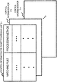
- FIG. 10 shows a configuration example of a control information database DB 4.
- the control information DB 4 manages control information for each packet processing unit 3, as shown in FIG. 10 .
- Respective control apparatuses 1 refer to a region corresponding to an assigned packet processing unit 3 to determine a packet handling operation to be notified to the packet processing unit 3.
- the respective control apparatuses 1 may update information of the region corresponding to the assigned packet processing unit 3.
- the control apparatus 1 refers to the control information DB 4 to determine the packet handling operation.
- the control apparatus 1 may periodically refer to the control information DB 4, and in a case where a packet handling operation that should be notified to the packet processing unit 3 is confirmed, may give notification of the packet handling operation to the packet processing unit 3.
- the control apparatus 1 may refer to the control information DB 4, in response to receiving a control message indicating a database update from the control information DB 4.
- FIG. 11 shows an operational example in a case where a control apparatus 1 assigned to a certain packet processing unit 3 is switched.
- FIG. 11 shows an example where the control apparatus assigned to the packet processing unit 3-1 is switched from the control apparatus 1-1 to the control apparatus 1-2.
- the assignment unit 2 determines a control apparatus 1 to control the packet processing unit 3 in place of the control apparatus in which the failure has occurred.
- the assignment unit 2 switches the control apparatus 1 in which the failure has occurred to the determined control apparatus 1.
- the control apparatus 1-1 stops referring to control information for the packet processing unit 3-1.
- the control apparatus 1-2 that is newly in charge of controlling the packet processing unit 3-1 starts making reference to control information for the packet processing unit 3-1, and takes over control of the packet processing unit 3-1. It is to be noted that since the control apparatuses 1-1 and 1-2 share the control information DB 4, the control apparatus 1-2 need not execute processing relating to taking over control, between itself and the control apparatus 1-1.
- FIG. 12 shows an operational example in a case where a control apparatus 1 is newly added to a system.
- FIG. 12 shows an example where a control apparatus 1-x is added to the system.
- the assignment unit 2 assigns a packet processing unit 3-x to the added control apparatus 1-x.
- the control apparatus 1-x refers to control information for the packet processing unit 3-x, and controls the packet processing unit 3-x.
- a control apparatus can start controlling a packet processing unit 3.
- a control apparatus 1 performs centralized control of a plurality of packet processing units 3
- increasing the number of control apparatuses 1 can be considered in order to inhibit load increase on the control apparatus 1.
- a system manager can very easily increase the control apparatuses 1. In a case of switching a control apparatus in order to avoid a failure, it is possible to switch the control apparatus by only changing a database reference, and the system manager can very easily switch a control apparatus.
- the respective control apparatuses 1 do not individually hold control information, a change to an assignment of a packet processing unit 3 is also easy.
- the control apparatus 1 need only change a reference for the control information DB 4.
- movement of control information is necessary when an assignment change is made.
- processing to move the control information need not be executed.
- a fourth exemplary embodiment illustrates an example in which the present disclosure is implemented by improving technology known as OpenFlow that has a centralized control architecture.
- FIG. 13 shows an outline of a communication system configured according to OpenFlow. It is to be noted that a flow, for example, indicates a sequence of communication packet groups having a prescribed attribute.
- An OpenFlow switch 600 is a network switch that uses OpenFlow technology.
- An OpenFlow controller 700 is an information processing device that controls the OpenFlow switches 600.
- the OpenFlow switch 600 communicates with the OpenFlow controller via a secure channel 701 configured between the OpenFlow switch 600 and the OpenFlow controller 700.
- the OpenFlow controller 700 configures a flow table 601 of the OpenFlow switch 600 via the secure channel 701. It is to be noted that the secure channel 701 is a communication path adopted in order to prevent bugging or manipulation of communication between the switch and controller.
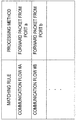
- FIG. 14 shows a configuration example of respective entries (flow entries) of the flow table 601.
- a flow entry is composed of a matching rule for matching information (for example, destination IP address or VLAN ID) of a packet received by a switch, flow statistical information (Counters) that is statistical information for each packet flow, and actions (Actions) defining a processing method of a packet matching the matching rule.
- a matching rule for matching information for example, destination IP address or VLAN ID
- Counters flow statistical information
- Actions actions
- the OpenFlow switch 600 On receiving a packet, the OpenFlow switch 600 refers to the flow table 601.
- the OpenFlow switch 600 searches for a flow entry that matches header information of the received packet.
- the OpenFlow switch 600 processes the received packet in accordance with a processing method defined in an action field of the retrieved entry.
- the processing method has definitions of, for example, "forward the received packet from a prescribed port", "drop the received packet”, "rewrite a part of the header of the received packet and forward from a prescribed port”.
- the OpenFlow switch 600 forwards the received packet to the OpenFlow controller 700 via the secure channel 701.
- the OpenFlow switch 600 requests configuration of a flow entry defining a processing method for the received packet, with respect to the controller. It is to be noted that in a case where the received packet matches an entry specifying requesting configuration of a flow entry with respect to the OpenFlow controller 700, the OpenFlow switch 600 may request configuration of the flow entry with respect to the OpenFlow controller 700.
- the OpenFlow controller 700 determines a processing method for the received packet, and configures a flow entry including the determined processing method in the flow table 601. Thereafter, the OpenFlow switch 600 processes subsequent packets belonging to the same flow as the received packet in accordance with the configured flow entry.
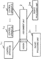
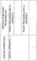
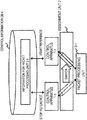
- FIG. 15 and FIG. 16 respectively show configuration examples of a control apparatus 1A and a packet processing unit 3A of the fourth exemplary embodiment.
- the control apparatus of FIG. 15 has a configuration whereby a control information DB 4 is shared with another control apparatus, as in the third exemplary embodiment.
- FIG. 15 shows a configuration example of the control apparatus 1A of the fourth exemplary embodiment.
- the control apparatus 1A includes a communication unit 10, a control unit 11, and an assignment management DB 12.
- the communication unit 10 communicates with a packet processing unit 3A assigned to the control apparatus 1A.
- the communication unit 10 gives notification of a packet handling operation to the packet processing unit 3A.
- the communication unit 10 receives a request for transmission of the packet handling operation from the packet processing unit 3A.
- the communication unit 10 communicates with the packet processing unit 3A via a control channel established with the packet processing unit 3A.
- the assignment management DB 12 manages the packet processing unit 3A assigned to the control apparatus 1A.
- the assignment management DB 12 manages identification information of the packet processing unit assigned to the control apparatus 1A.
- the control unit 11 refers to the assignment management DB 12 and recognizes the packet processing unit 3A assigned to the control apparatus 1A.
- the control unit 11 refers to control information related to the packet processing unit 3A assigned to the control apparatus 1A, from the control information DB 4.
- the control unit 11 determines a packet handling operation to be notified to the packet processing unit 3A based on the control information referred to.
- the control unit 11, for example, determines the packet handling operation in response to a request from the packet processing unit 3A.
- the control unit 11, for example, may refer to the control information DB 4 autonomously and give notification of the packet handling operation to the packet processing unit 3A.
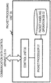
- FIG. 16 shows a configuration example of the packet processing unit 3A of the fourth exemplary embodiment.
- the packet processing unit 3A includes a communication unit 30, a packet processor 31, and a packet handling operation DB 32.
- the packet processor 31 On receiving a packet, the packet processor 31 searches for a packet handling operation corresponding to the received packet, from the packet handling operation DB 32. The packet processor 31 compares a matching rule of the packet handling operation and header information of the received packet, for example, and searches for a packet handling operation having a matching rule that matches the packet.
- the packet processor 31 processes packets in accordance with a processing method specified in the packet handling operation corresponding to the received packet.
- the packet processor 31 makes an enquiry for a packet handling operation corresponding to the received packet, with respect to the control apparatus.
- the assignment unit 2 forwards the enquiry received from the packet processing unit 3A to the control apparatus 1A assigned to the packet processing unit 3A.
- the assignment unit 2 for example, has a database that manages the control apparatus 1A assigned to the packet processing unit 3A.
- the assignment unit 2 for example, has a database that manages identification information and communication address (for example, IP address) of the control information assigned to the packet processing unit 3A.
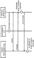
- FIG. 17 is a sequence diagram showing an operational example of the fourth exemplary embodiment.
- FIG. 17 is an example, and operations of the fourth exemplary embodiment are not limited to FIG. 17 .
- the assignment unit 2 assigns the control apparatus 1A to the packet processing unit 3A.
- the assignment unit 2 for example, determines the control apparatus 1A assigned to the packet processing unit 3A, based on a method illustrated in the second exemplary embodiment.
- the packet processing unit 3A makes an enquiry regarding a packet handling operation corresponding to a received packet, with respect to the assigned control apparatus 1A.
- the control apparatus 1A that receives the enquiry determines a packet handling operation and gives notification of the determined packet handling operation to the packet processing unit 3A.
- the packet processing unit 3A processes the packet in accordance with the notified packet handling operation.
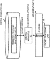
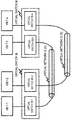
- FIG. 18 shows an example of a system configuration of a fifth exemplary embodiment.
- the system of the fifth exemplary embodiment includes a plurality of control apparatuses 1B, an assignment unit 2, a virtual switch (vSwitch) 3B, a server 5, a physical switch 6, and a virtual machine (VM) 7.
- vSwitch virtual switch
- VM virtual machine
- the virtual switch 3B is a network switch configured by software run by the server 5.
- the virtual switch 3B has a function corresponding to a packet processing unit 3 of the other exemplary embodiments. That is, the virtual switch 3B processes packets based on control by a control apparatus 1B. It is to be noted that the virtual switch 3B is positioned, for example, at an edge of a network configured by the physical switches 6.
- the plurality of control apparatuses 1B share a control information DB 4.
- the virtual machine (VM) 7 which is a computer configured by software, is run on the server 5.
- the virtual machine 7 communicates with another virtual machine 7 via the virtual switch 3B.
- the assignment unit 2 assigns the control apparatus 1B to the respective virtual switches 3B.
- the virtual switches 3B process a packet in accordance with a packet handling operation notified by the assigned control apparatus 1B.
- the server 5 is positioned at an edge of the network configured by the physical switches 6, for example.
- the control apparatus 1B controls operation of the virtual switch 3B present at the edge of the network.
- the virtual machine 7 communicates with another virtual machine 7 via the virtual network built on the physical switches 6.
- the virtual network for example, is built based on a protocol such as a VLAN (Virtual LAN) or NVGRE (Network Virtualization using Generic Routing Encapsulation).
- the virtual machine 7 communicates via the virtual network built on the physical switches 6.
- communication between virtual machine 7-1 and virtual machine 7-3 is executed via a tunnel for which a virtual network ID is "A”
- communication between virtual machine 7-2 and virtual machine 7-4 is executed via a tunnel for which a virtual network ID is "B”.
- the control apparatus 1B assigned to the virtual switch 3B-1 gives notification to the virtual switch 3B-1 of a packet handling operation specifying assigning a tag (for example, a VLAN tag) of the virtual network ID "A" to a packet with a destination of the virtual machine 7-3.
- a tag for example, a VLAN tag
- the virtual switch 3B-1 assigns the tag indicating the virtual network ID "A" to the packet, in accordance with an instruction of the control apparatus 1B.
- the control apparatus 1B assigned to the virtual switch 3B-2 gives notification to the virtual switch 3B-2 of a packet handling operation specifying assigning a tag (for example, a VLAN tag) of the virtual network ID "B" to a packet with a destination of the virtual machine 7-4.
- a tag for example, a VLAN tag
- the virtual switch 3B-2 assigns the tag indicating the virtual network ID "B" to the packet, in accordance with an instruction of the control apparatus 1B.
- the physical switch 6 holds in advance a configuration (for example, a port number with respect to which a packet with the virtual network ID "A" is to be forwarded) of a packet forwarding method based on the virtual network ID tag.
- control apparatus 1B controls only the virtual switch 3B, as in the fifth exemplary embodiment, it is possible to inhibit load increase on the control apparatus 1B. Furthermore, it is possible to install a network with centralized control by the control apparatuses, without replacing existing facilities (for example, the physical switches 6) of the communication system.
Landscapes
- Engineering & Computer Science (AREA)
- Computer Networks & Wireless Communication (AREA)
- Signal Processing (AREA)
- Data Exchanges In Wide-Area Networks (AREA)
- Mobile Radio Communication Systems (AREA)
- Selective Calling Equipment (AREA)
Applications Claiming Priority (2)
| Application Number | Priority Date | Filing Date | Title |
|---|---|---|---|
| JP2012135031 | 2012-06-14 | ||
| PCT/JP2013/003673 WO2013187054A1 (en) | 2012-06-14 | 2013-06-12 | Communication system, control apparatus, communication method, control method and program |
Publications (3)
| Publication Number | Publication Date |
|---|---|
| EP2862322A1 EP2862322A1 (en) | 2015-04-22 |
| EP2862322A4 EP2862322A4 (en) | 2016-01-20 |
| EP2862322B1 true EP2862322B1 (en) | 2019-10-02 |
Family
ID=49757899
Family Applications (1)
| Application Number | Title | Priority Date | Filing Date |
|---|---|---|---|
| EP13803867.4A Active EP2862322B1 (en) | 2012-06-14 | 2013-06-12 | Communication system, control apparatus, communication method, control method and program |
Country Status (8)
| Country | Link |
|---|---|
| US (1) | US10212084B2 (enExample) |
| EP (1) | EP2862322B1 (enExample) |
| JP (1) | JP6323339B2 (enExample) |
| KR (1) | KR20150016314A (enExample) |
| CN (1) | CN104365069A (enExample) |
| HK (1) | HK1208572A1 (enExample) |
| IN (1) | IN2014DN10624A (enExample) |
| WO (1) | WO2013187054A1 (enExample) |
Families Citing this family (8)
| Publication number | Priority date | Publication date | Assignee | Title |
|---|---|---|---|---|
| JP3065131B2 (ja) | 1991-08-02 | 2000-07-12 | 積水化学工業株式会社 | 繊維複合雨樋の製造方法 |
| US9397917B2 (en) * | 2014-01-10 | 2016-07-19 | Huawei Technologies Co., Ltd. | System and method for zoning in software defined networks |
| WO2015133561A1 (ja) * | 2014-03-06 | 2015-09-11 | 日本電気株式会社 | 通信システム、制御装置、通信装置及び通信方法 |
| US9445279B2 (en) | 2014-12-05 | 2016-09-13 | Huawei Technologies Co., Ltd. | Systems and methods for placing virtual serving gateways for mobility management |
| US11431569B2 (en) | 2016-07-21 | 2022-08-30 | Nec Corporation | Communication apparatus, system, rollback method, and non-transitory medium |
| JP6543600B2 (ja) * | 2016-08-17 | 2019-07-10 | 日本電信電話株式会社 | 管理システム、及び管理方法 |
| CN107592226A (zh) * | 2017-09-15 | 2018-01-16 | 厦门拓宝科技有限公司 | 多种不同设备类型的集中管控方法 |
| JP7003864B2 (ja) * | 2018-07-24 | 2022-02-10 | 日本電信電話株式会社 | 振分装置、通信システムおよび振分方法 |
Citations (1)
| Publication number | Priority date | Publication date | Assignee | Title |
|---|---|---|---|---|
| WO2011065268A1 (ja) * | 2009-11-26 | 2011-06-03 | 日本電気株式会社 | 負荷分散システム、負荷分散方法、及びプログラム |
Family Cites Families (14)
| Publication number | Priority date | Publication date | Assignee | Title |
|---|---|---|---|---|
| JP4169710B2 (ja) * | 2004-02-23 | 2008-10-22 | 日本電信電話株式会社 | Bgp経路情報管理システムおよびそのプログラム |
| JP2006227963A (ja) * | 2005-02-18 | 2006-08-31 | Fujitsu Ltd | 多段負荷分散装置、方法及びプログラム |
| US7536481B2 (en) * | 2005-02-25 | 2009-05-19 | Microsoft Corporation | Method and system for re-synchronizing end points when an intermediary detects that the end points may be unsynchronized |
| CN100389392C (zh) * | 2006-05-29 | 2008-05-21 | 杭州华三通信技术有限公司 | 一种集群系统中实现负载均衡的方法、系统和存储控制器 |
| US20080189769A1 (en) | 2007-02-01 | 2008-08-07 | Martin Casado | Secure network switching infrastructure |
| JP2009213097A (ja) | 2008-03-06 | 2009-09-17 | Nippon Telegr & Teleph Corp <Ntt> | 情報記録システムおよび情報記録方法 |
| JP4559512B2 (ja) * | 2008-08-11 | 2010-10-06 | 日本電信電話株式会社 | パケット転送システムおよびパケット転送方法 |
| EP2553901B1 (en) * | 2010-03-26 | 2016-04-27 | Citrix Systems, Inc. | System and method for link load balancing on a multi-core device |
| JP5670796B2 (ja) | 2010-09-06 | 2015-02-18 | 西日本電信電話株式会社 | 仮想系動作を実現する方法および通信装置 |
| US9001827B2 (en) * | 2010-12-17 | 2015-04-07 | Big Switch Networks, Inc. | Methods for configuring network switches |
| US9185056B2 (en) * | 2011-09-20 | 2015-11-10 | Big Switch Networks, Inc. | System and methods for controlling network traffic through virtual switches |
| US8705536B2 (en) * | 2012-03-05 | 2014-04-22 | Telefonaktiebolaget L M Ericsson (Publ) | Methods of operating forwarding elements including shadow tables and related forwarding elements |
| US8730806B2 (en) * | 2012-04-03 | 2014-05-20 | Telefonaktiebolaget L M Ericsson (Publ) | Congestion control and resource allocation in split architecture networks |
| US8908539B1 (en) * | 2012-05-25 | 2014-12-09 | Google Inc. | Systems and methods for testing network connections of a centrally-controlled network |
-
2013
- 2013-06-12 IN IN10624DEN2014 patent/IN2014DN10624A/en unknown
- 2013-06-12 CN CN201380030383.0A patent/CN104365069A/zh active Pending
- 2013-06-12 US US14/407,434 patent/US10212084B2/en active Active
- 2013-06-12 JP JP2014560154A patent/JP6323339B2/ja active Active
- 2013-06-12 KR KR1020147034165A patent/KR20150016314A/ko not_active Ceased
- 2013-06-12 WO PCT/JP2013/003673 patent/WO2013187054A1/en not_active Ceased
- 2013-06-12 EP EP13803867.4A patent/EP2862322B1/en active Active
- 2013-06-12 HK HK15109019.1A patent/HK1208572A1/xx unknown
Patent Citations (1)
| Publication number | Priority date | Publication date | Assignee | Title |
|---|---|---|---|---|
| WO2011065268A1 (ja) * | 2009-11-26 | 2011-06-03 | 日本電気株式会社 | 負荷分散システム、負荷分散方法、及びプログラム |
Non-Patent Citations (1)
| Title |
|---|
| CRAIG ELLROD: "Load Balancing - Least Connections | Citrix Blogs", 2 September 2010 (2010-09-02), pages 1 - 8, XP055361738, Retrieved from the Internet <URL:https://www.citrix.com/blogs/2010/09/02/load-balancing-least-connections/> [retrieved on 20170404] * |
Also Published As
| Publication number | Publication date |
|---|---|
| HK1208572A1 (en) | 2016-03-04 |
| EP2862322A1 (en) | 2015-04-22 |
| JP2015519765A (ja) | 2015-07-09 |
| KR20150016314A (ko) | 2015-02-11 |
| IN2014DN10624A (enExample) | 2015-09-11 |
| EP2862322A4 (en) | 2016-01-20 |
| US20150156113A1 (en) | 2015-06-04 |
| WO2013187054A1 (en) | 2013-12-19 |
| CN104365069A (zh) | 2015-02-18 |
| JP6323339B2 (ja) | 2018-05-16 |
| US10212084B2 (en) | 2019-02-19 |
Similar Documents
| Publication | Publication Date | Title |
|---|---|---|
| EP2862322B1 (en) | Communication system, control apparatus, communication method, control method and program | |
| JP5074327B2 (ja) | 経路制御システム | |
| US20140241367A1 (en) | Communication system, controller, communication method, and program | |
| US10263809B2 (en) | Selecting an optimal network device for reporting flow table misses upon expiry of a flow in a software defined network | |
| US20180077048A1 (en) | Controller, control method and program | |
| US20130286844A1 (en) | Information system, control apparatus, communication method, and program | |
| US9860170B2 (en) | Method, device, and system for packet routing in a network | |
| JPWO2016157864A1 (ja) | ネットワークシステム、ネットワーク制御方法および制御装置 | |
| WO2012050071A1 (ja) | 通信システム、制御装置、処理規則の設定方法およびプログラム | |
| US10122654B2 (en) | Divided hierarchical network system based on software-defined networks | |
| US20150341267A1 (en) | Control apparatus, communication apparatus, communication system, switch control method, and program | |
| WO2013186825A1 (en) | Computer system, communication control server, communication control method, and program | |
| JP2016192661A (ja) | ネットワークシステム、ネットワーク制御方法および制御装置 | |
| WO2014080993A1 (ja) | 通信システム、仮想ネットワーク管理装置、通信ノード、通信方法及びプログラム | |
| EP3399424B1 (en) | Using unified api to program both servers and fabric for forwarding for fine-grained network optimizations | |
| WO2014157512A1 (ja) | 仮想マシン提供システム、経路決定装置、経路制御方法及びプログラム | |
| CN105144644A (zh) | 通信节点、通信系统、分组处理方法和程序 | |
| US20150381775A1 (en) | Communication system, communication method, control apparatus, control apparatus control method, and program | |
| WO2014133025A1 (ja) | 通信システム、上位コントローラ、ネットワークの制御方法及びプログラム | |
| JP6292128B2 (ja) | 通信システム、ノード、制御装置、通信方法およびプログラム | |
| JPWO2015133561A1 (ja) | 通信システム、制御装置、通信装置及び通信方法 | |
| JP6127569B2 (ja) | スイッチ、制御装置、通信システム、制御チャネルの管理方法及びプログラム | |
| JP2016192660A (ja) | ネットワークシステム、ネットワーク制御方法、制御装置および運用管理装置 | |
| WO2015050197A1 (ja) | 通信システム、制御装置、通信方法及びプログラム | |
| WO2014142081A1 (ja) | 転送ノード、制御装置、通信システム、パケット処理方法及びプログラム |
Legal Events
| Date | Code | Title | Description |
|---|---|---|---|
| PUAI | Public reference made under article 153(3) epc to a published international application that has entered the european phase |
Free format text: ORIGINAL CODE: 0009012 |
|
| 17P | Request for examination filed |
Effective date: 20141216 |
|
| AK | Designated contracting states |
Kind code of ref document: A1 Designated state(s): AL AT BE BG CH CY CZ DE DK EE ES FI FR GB GR HR HU IE IS IT LI LT LU LV MC MK MT NL NO PL PT RO RS SE SI SK SM TR |
|
| AX | Request for extension of the european patent |
Extension state: BA ME |
|
| DAX | Request for extension of the european patent (deleted) | ||
| RA4 | Supplementary search report drawn up and despatched (corrected) |
Effective date: 20151223 |
|
| RIC1 | Information provided on ipc code assigned before grant |
Ipc: H04L 12/801 20130101ALI20151217BHEP Ipc: H04L 12/70 20130101ALI20151217BHEP Ipc: H04L 12/715 20130101ALI20151217BHEP Ipc: H04L 12/717 20130101AFI20151217BHEP Ipc: H04L 12/713 20130101ALI20151217BHEP Ipc: H04L 12/721 20130101ALI20151217BHEP |
|
| REG | Reference to a national code |
Ref country code: HK Ref legal event code: DE Ref document number: 1208572 Country of ref document: HK |
|
| STAA | Information on the status of an ep patent application or granted ep patent |
Free format text: STATUS: EXAMINATION IS IN PROGRESS |
|
| 17Q | First examination report despatched |
Effective date: 20170411 |
|
| GRAP | Despatch of communication of intention to grant a patent |
Free format text: ORIGINAL CODE: EPIDOSNIGR1 |
|
| STAA | Information on the status of an ep patent application or granted ep patent |
Free format text: STATUS: GRANT OF PATENT IS INTENDED |
|
| INTG | Intention to grant announced |
Effective date: 20190417 |
|
| GRAS | Grant fee paid |
Free format text: ORIGINAL CODE: EPIDOSNIGR3 |
|
| GRAA | (expected) grant |
Free format text: ORIGINAL CODE: 0009210 |
|
| STAA | Information on the status of an ep patent application or granted ep patent |
Free format text: STATUS: THE PATENT HAS BEEN GRANTED |
|
| AK | Designated contracting states |
Kind code of ref document: B1 Designated state(s): AL AT BE BG CH CY CZ DE DK EE ES FI FR GB GR HR HU IE IS IT LI LT LU LV MC MK MT NL NO PL PT RO RS SE SI SK SM TR |
|
| REG | Reference to a national code |
Ref country code: GB Ref legal event code: FG4D |
|
| REG | Reference to a national code |
Ref country code: CH Ref legal event code: EP Ref country code: AT Ref legal event code: REF Ref document number: 1187428 Country of ref document: AT Kind code of ref document: T Effective date: 20191015 |
|
| REG | Reference to a national code |
Ref country code: DE Ref legal event code: R096 Ref document number: 602013061267 Country of ref document: DE |
|
| REG | Reference to a national code |
Ref country code: IE Ref legal event code: FG4D |
|
| REG | Reference to a national code |
Ref country code: NL Ref legal event code: MP Effective date: 20191002 |
|
| REG | Reference to a national code |
Ref country code: LT Ref legal event code: MG4D |
|
| REG | Reference to a national code |
Ref country code: AT Ref legal event code: MK05 Ref document number: 1187428 Country of ref document: AT Kind code of ref document: T Effective date: 20191002 |
|
| PG25 | Lapsed in a contracting state [announced via postgrant information from national office to epo] |
Ref country code: SE Free format text: LAPSE BECAUSE OF FAILURE TO SUBMIT A TRANSLATION OF THE DESCRIPTION OR TO PAY THE FEE WITHIN THE PRESCRIBED TIME-LIMIT Effective date: 20191002 Ref country code: LV Free format text: LAPSE BECAUSE OF FAILURE TO SUBMIT A TRANSLATION OF THE DESCRIPTION OR TO PAY THE FEE WITHIN THE PRESCRIBED TIME-LIMIT Effective date: 20191002 Ref country code: ES Free format text: LAPSE BECAUSE OF FAILURE TO SUBMIT A TRANSLATION OF THE DESCRIPTION OR TO PAY THE FEE WITHIN THE PRESCRIBED TIME-LIMIT Effective date: 20191002 Ref country code: NL Free format text: LAPSE BECAUSE OF FAILURE TO SUBMIT A TRANSLATION OF THE DESCRIPTION OR TO PAY THE FEE WITHIN THE PRESCRIBED TIME-LIMIT Effective date: 20191002 Ref country code: AT Free format text: LAPSE BECAUSE OF FAILURE TO SUBMIT A TRANSLATION OF THE DESCRIPTION OR TO PAY THE FEE WITHIN THE PRESCRIBED TIME-LIMIT Effective date: 20191002 Ref country code: PT Free format text: LAPSE BECAUSE OF FAILURE TO SUBMIT A TRANSLATION OF THE DESCRIPTION OR TO PAY THE FEE WITHIN THE PRESCRIBED TIME-LIMIT Effective date: 20200203 Ref country code: BG Free format text: LAPSE BECAUSE OF FAILURE TO SUBMIT A TRANSLATION OF THE DESCRIPTION OR TO PAY THE FEE WITHIN THE PRESCRIBED TIME-LIMIT Effective date: 20200102 Ref country code: FI Free format text: LAPSE BECAUSE OF FAILURE TO SUBMIT A TRANSLATION OF THE DESCRIPTION OR TO PAY THE FEE WITHIN THE PRESCRIBED TIME-LIMIT Effective date: 20191002 Ref country code: LT Free format text: LAPSE BECAUSE OF FAILURE TO SUBMIT A TRANSLATION OF THE DESCRIPTION OR TO PAY THE FEE WITHIN THE PRESCRIBED TIME-LIMIT Effective date: 20191002 Ref country code: GR Free format text: LAPSE BECAUSE OF FAILURE TO SUBMIT A TRANSLATION OF THE DESCRIPTION OR TO PAY THE FEE WITHIN THE PRESCRIBED TIME-LIMIT Effective date: 20200103 Ref country code: NO Free format text: LAPSE BECAUSE OF FAILURE TO SUBMIT A TRANSLATION OF THE DESCRIPTION OR TO PAY THE FEE WITHIN THE PRESCRIBED TIME-LIMIT Effective date: 20200102 Ref country code: PL Free format text: LAPSE BECAUSE OF FAILURE TO SUBMIT A TRANSLATION OF THE DESCRIPTION OR TO PAY THE FEE WITHIN THE PRESCRIBED TIME-LIMIT Effective date: 20191002 |
|
| PG25 | Lapsed in a contracting state [announced via postgrant information from national office to epo] |
Ref country code: RS Free format text: LAPSE BECAUSE OF FAILURE TO SUBMIT A TRANSLATION OF THE DESCRIPTION OR TO PAY THE FEE WITHIN THE PRESCRIBED TIME-LIMIT Effective date: 20191002 Ref country code: HR Free format text: LAPSE BECAUSE OF FAILURE TO SUBMIT A TRANSLATION OF THE DESCRIPTION OR TO PAY THE FEE WITHIN THE PRESCRIBED TIME-LIMIT Effective date: 20191002 Ref country code: CZ Free format text: LAPSE BECAUSE OF FAILURE TO SUBMIT A TRANSLATION OF THE DESCRIPTION OR TO PAY THE FEE WITHIN THE PRESCRIBED TIME-LIMIT Effective date: 20191002 Ref country code: IS Free format text: LAPSE BECAUSE OF FAILURE TO SUBMIT A TRANSLATION OF THE DESCRIPTION OR TO PAY THE FEE WITHIN THE PRESCRIBED TIME-LIMIT Effective date: 20200224 |
|
| PG25 | Lapsed in a contracting state [announced via postgrant information from national office to epo] |
Ref country code: AL Free format text: LAPSE BECAUSE OF FAILURE TO SUBMIT A TRANSLATION OF THE DESCRIPTION OR TO PAY THE FEE WITHIN THE PRESCRIBED TIME-LIMIT Effective date: 20191002 |
|
| REG | Reference to a national code |
Ref country code: DE Ref legal event code: R097 Ref document number: 602013061267 Country of ref document: DE |
|
| PG2D | Information on lapse in contracting state deleted |
Ref country code: IS |
|
| PG25 | Lapsed in a contracting state [announced via postgrant information from national office to epo] |
Ref country code: RO Free format text: LAPSE BECAUSE OF FAILURE TO SUBMIT A TRANSLATION OF THE DESCRIPTION OR TO PAY THE FEE WITHIN THE PRESCRIBED TIME-LIMIT Effective date: 20191002 Ref country code: EE Free format text: LAPSE BECAUSE OF FAILURE TO SUBMIT A TRANSLATION OF THE DESCRIPTION OR TO PAY THE FEE WITHIN THE PRESCRIBED TIME-LIMIT Effective date: 20191002 Ref country code: DK Free format text: LAPSE BECAUSE OF FAILURE TO SUBMIT A TRANSLATION OF THE DESCRIPTION OR TO PAY THE FEE WITHIN THE PRESCRIBED TIME-LIMIT Effective date: 20191002 Ref country code: IS Free format text: LAPSE BECAUSE OF FAILURE TO SUBMIT A TRANSLATION OF THE DESCRIPTION OR TO PAY THE FEE WITHIN THE PRESCRIBED TIME-LIMIT Effective date: 20200202 |
|
| PLBE | No opposition filed within time limit |
Free format text: ORIGINAL CODE: 0009261 |
|
| STAA | Information on the status of an ep patent application or granted ep patent |
Free format text: STATUS: NO OPPOSITION FILED WITHIN TIME LIMIT |
|
| PG25 | Lapsed in a contracting state [announced via postgrant information from national office to epo] |
Ref country code: SK Free format text: LAPSE BECAUSE OF FAILURE TO SUBMIT A TRANSLATION OF THE DESCRIPTION OR TO PAY THE FEE WITHIN THE PRESCRIBED TIME-LIMIT Effective date: 20191002 Ref country code: IT Free format text: LAPSE BECAUSE OF FAILURE TO SUBMIT A TRANSLATION OF THE DESCRIPTION OR TO PAY THE FEE WITHIN THE PRESCRIBED TIME-LIMIT Effective date: 20191002 Ref country code: SM Free format text: LAPSE BECAUSE OF FAILURE TO SUBMIT A TRANSLATION OF THE DESCRIPTION OR TO PAY THE FEE WITHIN THE PRESCRIBED TIME-LIMIT Effective date: 20191002 |
|
| 26N | No opposition filed |
Effective date: 20200703 |
|
| PG25 | Lapsed in a contracting state [announced via postgrant information from national office to epo] |
Ref country code: SI Free format text: LAPSE BECAUSE OF FAILURE TO SUBMIT A TRANSLATION OF THE DESCRIPTION OR TO PAY THE FEE WITHIN THE PRESCRIBED TIME-LIMIT Effective date: 20191002 |
|
| PG25 | Lapsed in a contracting state [announced via postgrant information from national office to epo] |
Ref country code: MC Free format text: LAPSE BECAUSE OF FAILURE TO SUBMIT A TRANSLATION OF THE DESCRIPTION OR TO PAY THE FEE WITHIN THE PRESCRIBED TIME-LIMIT Effective date: 20191002 |
|
| REG | Reference to a national code |
Ref country code: CH Ref legal event code: PL |
|
| PG25 | Lapsed in a contracting state [announced via postgrant information from national office to epo] |
Ref country code: LU Free format text: LAPSE BECAUSE OF NON-PAYMENT OF DUE FEES Effective date: 20200612 |
|
| REG | Reference to a national code |
Ref country code: BE Ref legal event code: MM Effective date: 20200630 |
|
| PG25 | Lapsed in a contracting state [announced via postgrant information from national office to epo] |
Ref country code: IE Free format text: LAPSE BECAUSE OF NON-PAYMENT OF DUE FEES Effective date: 20200612 Ref country code: LI Free format text: LAPSE BECAUSE OF NON-PAYMENT OF DUE FEES Effective date: 20200630 Ref country code: CH Free format text: LAPSE BECAUSE OF NON-PAYMENT OF DUE FEES Effective date: 20200630 Ref country code: FR Free format text: LAPSE BECAUSE OF NON-PAYMENT OF DUE FEES Effective date: 20200630 |
|
| PG25 | Lapsed in a contracting state [announced via postgrant information from national office to epo] |
Ref country code: BE Free format text: LAPSE BECAUSE OF NON-PAYMENT OF DUE FEES Effective date: 20200630 |
|
| REG | Reference to a national code |
Ref country code: DE Ref legal event code: R079 Ref document number: 602013061267 Country of ref document: DE Free format text: PREVIOUS MAIN CLASS: H04L0012717000 Ipc: H04L0045420000 |
|
| REG | Reference to a national code |
Ref country code: HK Ref legal event code: WD Ref document number: 1208572 Country of ref document: HK |
|
| PG25 | Lapsed in a contracting state [announced via postgrant information from national office to epo] |
Ref country code: TR Free format text: LAPSE BECAUSE OF FAILURE TO SUBMIT A TRANSLATION OF THE DESCRIPTION OR TO PAY THE FEE WITHIN THE PRESCRIBED TIME-LIMIT Effective date: 20191002 Ref country code: MT Free format text: LAPSE BECAUSE OF FAILURE TO SUBMIT A TRANSLATION OF THE DESCRIPTION OR TO PAY THE FEE WITHIN THE PRESCRIBED TIME-LIMIT Effective date: 20191002 Ref country code: CY Free format text: LAPSE BECAUSE OF FAILURE TO SUBMIT A TRANSLATION OF THE DESCRIPTION OR TO PAY THE FEE WITHIN THE PRESCRIBED TIME-LIMIT Effective date: 20191002 |
|
| PG25 | Lapsed in a contracting state [announced via postgrant information from national office to epo] |
Ref country code: MK Free format text: LAPSE BECAUSE OF FAILURE TO SUBMIT A TRANSLATION OF THE DESCRIPTION OR TO PAY THE FEE WITHIN THE PRESCRIBED TIME-LIMIT Effective date: 20191002 |
|
| PGFP | Annual fee paid to national office [announced via postgrant information from national office to epo] |
Ref country code: DE Payment date: 20250618 Year of fee payment: 13 |
|
| PGFP | Annual fee paid to national office [announced via postgrant information from national office to epo] |
Ref country code: GB Payment date: 20250618 Year of fee payment: 13 |
|
| REG | Reference to a national code |
Ref country code: DE Ref legal event code: R081 Ref document number: 602013061267 Country of ref document: DE Owner name: NEC ASIA PACIFIC PTE LTD., SG Free format text: FORMER OWNER: NEC CORPORATION, TOKYO, JP |
|
| REG | Reference to a national code |
Ref country code: GB Ref legal event code: 732E Free format text: REGISTERED BETWEEN 20260319 AND 20260325 |