WO2013187054A1 - Communication system, control apparatus, communication method, control method and program - Google Patents
Communication system, control apparatus, communication method, control method and program Download PDFInfo
- Publication number
- WO2013187054A1 WO2013187054A1 PCT/JP2013/003673 JP2013003673W WO2013187054A1 WO 2013187054 A1 WO2013187054 A1 WO 2013187054A1 JP 2013003673 W JP2013003673 W JP 2013003673W WO 2013187054 A1 WO2013187054 A1 WO 2013187054A1
- Authority
- WO
- WIPO (PCT)
- Prior art keywords
- packet
- control apparatus
- packet processing
- control
- processing means
- Prior art date
Links
Images


Classifications
-
- H—ELECTRICITY
- H04—ELECTRIC COMMUNICATION TECHNIQUE
- H04L—TRANSMISSION OF DIGITAL INFORMATION, e.g. TELEGRAPHIC COMMUNICATION
- H04L12/00—Data switching networks
-
- H—ELECTRICITY
- H04—ELECTRIC COMMUNICATION TECHNIQUE
- H04L—TRANSMISSION OF DIGITAL INFORMATION, e.g. TELEGRAPHIC COMMUNICATION
- H04L47/00—Traffic control in data switching networks
- H04L47/10—Flow control; Congestion control
-
- H—ELECTRICITY
- H04—ELECTRIC COMMUNICATION TECHNIQUE
- H04L—TRANSMISSION OF DIGITAL INFORMATION, e.g. TELEGRAPHIC COMMUNICATION
- H04L45/00—Routing or path finding of packets in data switching networks
- H04L45/38—Flow based routing
-
- H—ELECTRICITY
- H04—ELECTRIC COMMUNICATION TECHNIQUE
- H04L—TRANSMISSION OF DIGITAL INFORMATION, e.g. TELEGRAPHIC COMMUNICATION
- H04L45/00—Routing or path finding of packets in data switching networks
- H04L45/42—Centralised routing
-
- H—ELECTRICITY
- H04—ELECTRIC COMMUNICATION TECHNIQUE
- H04L—TRANSMISSION OF DIGITAL INFORMATION, e.g. TELEGRAPHIC COMMUNICATION
- H04L45/00—Routing or path finding of packets in data switching networks
- H04L45/58—Association of routers
- H04L45/586—Association of routers of virtual routers
-
- H—ELECTRICITY
- H04—ELECTRIC COMMUNICATION TECHNIQUE
- H04L—TRANSMISSION OF DIGITAL INFORMATION, e.g. TELEGRAPHIC COMMUNICATION
- H04L45/00—Routing or path finding of packets in data switching networks
- H04L45/64—Routing or path finding of packets in data switching networks using an overlay routing layer
Definitions
- the present invention is based upon and claims the benefit of priority of Japanese Patent Application No. 2012-135031, filed on June 14, 2012, the disclosure of which is incorporated herein in its entirety by reference thereto.
- the present invention relates to a communication system, a control apparatus, a communication method, a control method and program, and relates to a communication system, a control apparatus, a communication method, a control method and program that process packets in accordance with control by the control apparatus.
- Patent Literature 1 discloses technology in which switches in a communication system process packets in accordance with an instruction notified by a control apparatus.
- the control apparatus performs centralized control of a plurality of switches in the communication system.
- Non Patent Literature 1 discloses technology in which a plurality of control apparatuses share control of a plurality of switches in a communication system.
- Non Patent Literature 1 discloses sharing control of communication equipment by a plurality of control apparatuses, but there is no disclosure concerning a configuration that facilitates operation management of a plurality of control apparatuses, with regard to avoiding control apparatus failure and the like.
- a communication system comprising: a plurality of control apparatuses that determine a packet handling operation (packet processing rule); a plurality of packet processing means that process a packet in accordance with the packet handling operation notified by the control apparatus; assignment means that assigns, with respect to each of the plurality of packet processing means, a control apparatus that controls the packet processing means concerned; and a database that is shared by the plurality of control apparatuses and that stores information related to the packet handling operation; wherein each of the control apparatuses refers to the database to determine the packet handling operation.
- packet processing rule packet processing rule
- packet processing means that process a packet in accordance with the packet handling operation notified by the control apparatus
- assignment means that assigns, with respect to each of the plurality of packet processing means, a control apparatus that controls the packet processing means concerned
- a database that is shared by the plurality of control apparatuses and that stores information related to the packet handling operation; wherein each of the control apparatuses refers to the database to determine the packet handling operation.
- a control apparatus which controls packet processing, comprising: first means that refers to a database shared by the control apparatus and another control apparatus, and determines a packet handling operation related to a processing method for the packet; and second means that notifies the determined packet handling operation to, among a plurality of packet processing means, a packet processing means assigned to the control apparatus.
- a communication method by which a plurality of control apparatuses control packet processing, comprising: assigning, to each of a plurality of packet processing means, a control apparatus that controls the packet processing means concerned; determining, by each of the control apparatuses, a packet handling operation for processing a packet, by referring to a database shared by the plurality of control apparatuses; and notifying, by each of the control apparatuses, the determined packet handling operation to the assigned packet processing means.
- a control method for a control apparatus that controls processing of a packet, comprising: determining a packet handling operation related to a method of processing the packet, by referring to a database shared by the control apparatus and another control apparatus; and notifying the determined packet handling operation to, among a plurality of packet processing means, a packet processing means assigned to the control apparatus.
- a program that executes, in a control apparatus that controls processing of a packet, a process of determining a packet handling operation related to a method of processing the packet, by referring to a database shared by the control apparatus and another control apparatus; and a process of notifying the determined packet handling operation to, among a plurality of packet processing means, a packet processing means assigned to the control apparatus.
- This program can be recorded in a computer-readable storage medium which may be non-transitory. That is, the present disclosure may be embodied as a computer program product.
- the present invention contributes to distribution of load on a control apparatus and of facilitating operation management of a plurality of control apparatuses.
- FIG. 1 is a diagram showing an example of a system configuration of a first exemplary embodiment.
- FIG. 2 is a diagram showing an operational example of the first exemplary embodiment.
- FIG. 3 is a diagram showing an operational example of the first exemplary embodiment.
- FIG. 4 is a diagram showing an example of a database referred to by a control apparatus.
- FIG. 5 is a flowchart showing an operational example of the first exemplary embodiment.
- FIG. 6 is a diagram showing an example of a configuration of an assignment unit.
- FIG. 7 is a diagram showing an example of a database possessed by the assignment unit.
- FIG. 8 is a diagram showing an example of the database possessed by the assignment unit.
- FIG. 9 is a diagram showing an example of the database possessed by the assignment unit.
- FIG. 1 is a diagram showing an example of a system configuration of a first exemplary embodiment.
- FIG. 2 is a diagram showing an operational example of the first exemplary embodiment.
- FIG. 3 is a diagram showing an
- FIG. 10 is a diagram showing an example of the database referred to by the control apparatus.
- FIG. 11 is a diagram showing an operational example of a third exemplary embodiment.
- FIG. 12 is a diagram showing an operational example of the third exemplary embodiment.
- FIG. 13 is a diagram describing technology related to a fourth exemplary embodiment.
- FIG. 14 is a diagram describing technology related to the fourth exemplary embodiment.
- FIG. 15 is a diagram showing an example of a configuration of a control apparatus in the fourth exemplary embodiment.
- FIG. 16 is a diagram showing an example of a configuration of a packet processing unit in the fourth exemplary embodiment.
- FIG. 17 is a sequence diagram showing an operational example of the fourth exemplary embodiment.
- FIG. 18 is a diagram showing an example of a system configuration of a fifth exemplary embodiment.
- FIG. 19 is a diagram showing an operational example of the fifth exemplary embodiment.
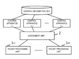
- FIG. 1 shows a configuration example of a communication system of a first exemplary embodiment.
- FIG. 1 is an example, and the configuration of the communication system of the present disclosure is not limited to FIG. 1.
- the communication system includes a plurality of control apparatuses 1, an assignment unit 2, a plurality of packet processing units 3, and a control information DB (Database) 4.
- the respective control apparatuses 1 share the control information DB 4, and refer to the control information DB 4 to control the packet processing units 3. Since the respective control apparatuses 1 share the database, the respective control apparatuses 1 need not store control information for controlling the packet processing units. Accordingly, in a case of switching a packet processing unit that is a target for control, or a case of replacing a control apparatus 1 in which a failure has occurred, the respective control apparatuses 1 need not execute processing such as handing over control information among the control apparatuses, and operation management of the control apparatuses is facilitated.
- the respective packet processing units 3 process packets in accordance with a packet handling operation (i.e. packet processing rule) notified by a control apparatus 1.
- a packet processing unit 3 executes processing such as packet forwarding, packet header rewriting, and packet dropping, in accordance with a packet handling operation notified by the control apparatus 1.
- the packet processing unit 3 is, for example, communication equipment such as a switch, a router, or the like.
- functionality equivalent to communication equipment such as a switch, a router, or the like may be configured by software (virtual switch).
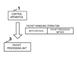
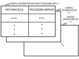
- FIG. 2 shows an example of a packet handling operation notified by the control apparatus 1 to the packet processing unit 3.
- control apparatus 1 transmits to the packet processing unit a packet handling operation including a packet processing method and a condition (matching rule) for identifying a packet that is a target of the processing method.
- the matching rule for example, is a rule identified based on information included in the packet, such as a packet to be transmitted to a prescribed destination or a packet transmitted from a prescribed transmission source.
- the packet processing unit 3 processes a packet conforming with a matching rule in accordance with a processing method corresponding to the matching rule.
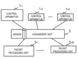
- the assignment unit 2 assigns, with regard to each of the packet processing units 3, a control apparatus 1 that controls a relevant packet processing unit 3.
- the assignment unit 2 for example, assigns the control apparatus 1-1 to the packet processing unit 3-1, as in the example of FIG. 3. It is to be noted that the assignment unit 2 manages the control apparatuses 1 and the packet processing units 3 present in the system.
- the assignment unit 2 may determine a control apparatus 1 to be assigned to a packet processing unit 3 every time a packet handling operation enquiry is transmitted from the packet processing unit 3. Furthermore, the assignment unit 2 may determine a packet processing unit 3 corresponding to a control apparatus 1 that has transmitted a packet handling operation every time the control apparatus 1 transmits the packet handling operation to the packet processing unit. That is, the assignment unit 2 may assign the control apparatuses to the respective packet processing units 3 at an arbitrary trigger.
- the assignment unit 2 may select a plurality of packet processing units 3 corresponding to a control apparatus 1.
- the packet processing units 3 process packets in accordance with an instruction notified by the control apparatus 1 assigned by the assignment unit 2. That is, the control apparatus 1 may control only the packet processing unit 3 assigned by the assignment unit 2. It is to be noted that the assignment unit 2 may assign a plurality of the packet processing units 3 to the control apparatus 1.
- the assignment unit 2 for example, assigns a corresponding control apparatus 1 to the respective packet processing units 3, based on identification information (for example, IP address, Datapath ID, or the like) of the packet processing units 3.
- the assignment unit 2 for example, assigns control apparatuses 1 so that load is distributed among each of the control apparatuses 1. For example, the assignment unit 2 allocates the control apparatuses 1 to the packet processing units 3, in a round robin manner.
- the control information DB 4 manages information related to packet handling operations notified to the assigned packet processing units 3 by the respective control apparatuses 1. It is to be noted that the control information DB 4 is configured by a plurality of databases, and the plurality of databases may be shared by the respective control apparatuses 1. By the configuration of a plurality of databases, the control information DB 4 has redundancy.
- FIG. 4 shows an example of information stored by the control information DB 4.
- FIG. 4 is an example, and the information stored by the control information DB 4 is not limited to FIG. 4.
- the control information DB 4 for example, manages candidate packet handling operations to be notified to the packet processing units 3. Furthermore, the control information DB 4, for example, may manage information (control policy or the like) used for generating a packet handling operation by a control apparatus 1.
- the control information DB 4 manages candidate packet handling operations to be notified to the packet processing units 3.
- the respective packet handling operations include a matching rule and a processing method.
- the packet processing units 3 process packets in accordance with a processing method specified in the packet handling operation.
- the packet processing unit 3 compares a matching rule and a received packet. In a case where the received packet matches the matching rule, the packet processing unit 3 processes the received packet by a processing method corresponding to the matching rule.
- the matching rule for example, is a condition for identifying a packet as a communication flow.
- a communication flow is a sequence of packets identified by a prescribed condition.
- the matching rule for example, is a rule identified based on information included in a packet, such as a packet to be transmitted to a prescribed destination or a packet transmitted from a prescribed transmission source.
- the respective control apparatuses 1 refer to the control information DB 4 to determine a packet handling operation to be notified to the assigned packet processing unit 3.
- the respective control apparatuses 1 may update content of the control information DB 4.
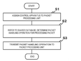
- FIG. 5 is a flowchart showing an operational example of the first exemplary embodiment.
- the assignment unit 2 assigns a control apparatus 1 to a packet processing unit 3 (S1).
- the control apparatus 1 refers to the control information DB 4 shared by the plurality of control apparatuses to determine a packet handling operation for notification to an assigned packet processing unit 3 (S2).
- the control apparatus 1 transmits a determined packet handling operation to the packet processing unit 3 (S3).
- the packet processing unit 3 processes a packet in accordance with the packet handling operation notified by the assigned control apparatus 1.
- a configuration example of a communication system in a second exemplary embodiment is similar to FIG. 1.
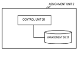
- FIG. 6 shows a configuration example of an assignment unit 2 with regard to the second exemplary embodiment.
- the assignment unit 2 assigns a control apparatus 1 to a packet processing unit 3.
- the assignment unit 2 includes a control unit 20 and a management DB (Database) 21.
- the control unit 20 refers to the management DB 21 to determine the control apparatus 1 to be assigned to the packet processing unit 3.
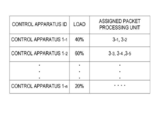
- FIG. 7 shows an example of a database possessed by the management DB 21.
- a configuration of the database possessed by the management DB 21 is not limited to FIG. 7.
- the control unit 20 gives consideration to the load of each of the control apparatuses 1, to assign a control apparatus 1 to a packet processing unit 3.
- the management DB 21 may manage an operation status of each control apparatus (for example, status indicating that a control apparatus is operating or is stopped).
- the control unit 20 refers to the management DB 21 at communication system startup or when a new packet processing unit 3 is added to the communication system, and performs assignment of the control apparatus 1.
- the control unit 20 may change the assignment of the control apparatuses 1 with respect to the packet processing units 3, for the entire communication system.
- the control unit 20 may refer to the management DB 21 to monitor the load situation of each control apparatus 1, and dynamically change the assignment of the control apparatuses 1 with respect to the packet processing units 3.
- the control unit 20, for example, dynamically changes the assignment for the packet processing units 3, so that the load on the respective control apparatuses 1 approaches the average load of the control apparatuses 1 of the entire system. For example, in a case where the load on a certain control apparatus 1 becomes higher than the average load of the respective control apparatuses by at least a prescribed threshold, the control unit 20 changes the assignment of the packet processing units 3. Furthermore, for example, in a case where the load on a certain control apparatus 1 becomes lower than the average load of the respective control apparatuses by at least a prescribed threshold, the control unit 20 changes the assignment of the packet processing units 3.
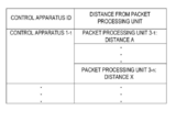
- the assignment unit 2 may assign the control apparatuses based on information related to the position of the packet processing units 3.
- the assignment unit 2 may refer to the distance between a control apparatus 1 and a packet processing unit 3, for example, as information related to position, to perform the assignment of the control apparatuses 1.
- the management DB 21 manages information related to the distance between the control apparatuses 1 and the packet processing units 3.
- the management DB 21, for example manages the distances to the respective packet processing units 3 included in the communication system, with respect to each control apparatus 1. It is to be noted that the assignment unit 2 may consider the load state exemplified in FIG. 7 and distances exemplified in FIG. 8, to perform assignment of the control apparatuses 1.
- the distance between the control apparatus 1 and the packet processing unit 3 for example, is a distance depending on position relationships of the control apparatus and the packet processing unit, or a distance determined based on network configuration (network topology) of the communication system.
- the distance between the control apparatus 1 and the packet processing unit 3 may also be the number of communication hops.
- the control unit 20 may assign to a packet processing unit a control apparatus whose distance from the packet processing unit 3 is a minimum, among control apparatuses 1 that are candidates for being assigned to the packet processing unit 3.
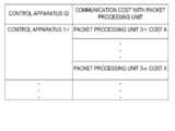
- the assignment unit 2 may refer to communication cost between the control apparatus 1 and the packet processing unit 3, as information related to position, to perform assignment of the control apparatus 1.
- the management DB 21 manages information related to the communication cost between the control apparatus 1 and the packet processing unit 3, as in the example of FIG. 9.
- the communication cost for example, is obtained from round trip time between the control apparatus 1 and the packet processing unit 3, or the number of communication hops between the control apparatus 1 and the packet processing unit 3.
- the control unit 20 assigns to a packet processing unit a control apparatus for which communication cost with regard to the packet processing unit 3 is a minimum, among the control apparatuses 1 that are candidates for being assigned to the packet processing unit 3.
- FIG. 10 shows a configuration example of a control information database DB 4.
- the control information DB 4 manages control information for each packet processing unit 3, as shown in FIG. 10.
- Respective control apparatuses 1 refer to a region corresponding to an assigned packet processing unit 3 to determine a packet handling operation to be notified to the packet processing unit 3.
- the respective control apparatuses 1 may update information of the region corresponding to the assigned packet processing unit 3.
- the control apparatus 1 refers to the control information DB 4 to determine the packet handling operation.
- the control apparatus 1 may periodically refer to the control information DB 4, and in a case where a packet handling operation that should be notified to the packet processing unit 3 is confirmed, may give notification of the packet handling operation to the packet processing unit 3.
- the control apparatus 1 may refer to the control information DB 4, in response to receiving a control message indicating a database update from the control information DB 4.
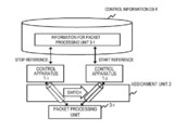
- FIG. 11 shows an operational example in a case where a control apparatus 1 assigned to a certain packet processing unit 3 is switched.
- FIG. 11 shows an example where the control apparatus assigned to the packet processing unit 3-1 is switched from the control apparatus 1-1 to the control apparatus 1-2.
- the assignment unit 2 determines a control apparatus 1 to control the packet processing unit 3 in place of the control apparatus in which the failure has occurred.
- the assignment unit 2 switches the control apparatus 1 in which the failure has occurred to the determined control apparatus 1.
- the control apparatus 1-1 stops referring to control information for the packet processing unit 3-1.
- the control apparatus 1-2 that is newly in charge of controlling the packet processing unit 3-1 starts making reference to control information for the packet processing unit 3-1, and takes over control of the packet processing unit 3-1. It is to be noted that since the control apparatuses 1-1 and 1-2 share the control information DB 4, the control apparatus 1-2 need not execute processing relating to taking over control, between itself and the control apparatus 1-1.
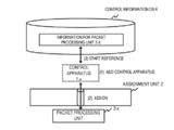
- FIG. 12 shows an operational example in a case where a control apparatus 1 is newly added to a system.
- FIG. 12 shows an example where a control apparatus 1-x is added to the system.
- the assignment unit 2 assigns a packet processing unit 3-x to the added control apparatus 1-x.
- the control apparatus 1-x refers to control information for the packet processing unit 3-x, and controls the packet processing unit 3-x.
- a control apparatus can start controlling a packet processing unit 3.
- a control apparatus 1 performs centralized control of a plurality of packet processing units 3
- increasing the number of control apparatuses 1 can be considered in order to inhibit load increase on the control apparatus 1.
- a system manager can very easily increase the control apparatuses 1. In a case of switching a control apparatus in order to avoid a failure, it is possible to switch the control apparatus by only changing a database reference, and the system manager can very easily switch a control apparatus.
- a fourth exemplary embodiment illustrates an example in which the present disclosure is implemented by improving technology known as OpenFlow that has a centralized control architecture.
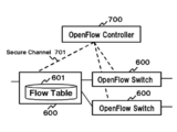
- FIG. 13 shows an outline of a communication system configured according to OpenFlow. It is to be noted that a flow, for example, indicates a sequence of communication packet groups having a prescribed attribute.
- An OpenFlow switch 600 is a network switch that uses OpenFlow technology.
- An OpenFlow controller 700 is an information processing device that controls the OpenFlow switches 600.
- the OpenFlow switch 600 communicates with the OpenFlow controller via a secure channel 701 configured between the OpenFlow switch 600 and the OpenFlow controller 700.
- the OpenFlow controller 700 configures a flow table 601 of the OpenFlow switch 600 via the secure channel 701. It is to be noted that the secure channel 701 is a communication path adopted in order to prevent bugging or manipulation of communication between the switch and controller.
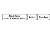
- FIG. 14 shows a configuration example of respective entries (flow entries) of the flow table 601.
- a flow entry is composed of a matching rule for matching information (for example, destination IP address or VLAN ID) of a packet received by a switch, flow statistical information (Counters) that is statistical information for each packet flow, and actions (Actions) defining a processing method of a packet matching the matching rule.
- a matching rule for matching information for example, destination IP address or VLAN ID
- Counters flow statistical information
- Actions actions
- the OpenFlow switch 600 On receiving a packet, the OpenFlow switch 600 refers to the flow table 601.
- the OpenFlow switch 600 searches for a flow entry that matches header information of the received packet.
- the OpenFlow switch 600 processes the received packet in accordance with a processing method defined in an action field of the retrieved entry.
- the processing method has definitions of, for example, "forward the received packet from a prescribed port", "drop the received packet”, "rewrite a part of the header of the received packet and forward from a prescribed port”.
- the OpenFlow switch 600 forwards the received packet to the OpenFlow controller 700 via the secure channel 701.
- the OpenFlow switch 600 requests configuration of a flow entry defining a processing method for the received packet, with respect to the controller. It is to be noted that in a case where the received packet matches an entry specifying requesting configuration of a flow entry with respect to the OpenFlow controller 700, the OpenFlow switch 600 may request configuration of the flow entry with respect to the OpenFlow controller 700.
- the OpenFlow controller 700 determines a processing method for the received packet, and configures a flow entry including the determined processing method in the flow table 601. Thereafter, the OpenFlow switch 600 processes subsequent packets belonging to the same flow as the received packet in accordance with the configured flow entry.
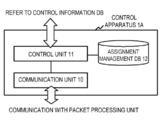
- FIG. 15 and FIG. 16 respectively show configuration examples of a control apparatus 1A and a packet processing unit 3A of the fourth exemplary embodiment.
- the control apparatus of FIG. 15 has a configuration whereby a control information DB 4 is shared with another control apparatus, as in the third exemplary embodiment.
- FIG. 15 shows a configuration example of the control apparatus 1A of the fourth exemplary embodiment.
- the control apparatus 1A includes a communication unit 10, a control unit 11, and an assignment management DB 12.
- the communication unit 10 communicates with a packet processing unit 3A assigned to the control apparatus 1A.
- the communication unit 10 gives notification of a packet handling operation to the packet processing unit 3A.
- the communication unit 10 receives a request for transmission of the packet handling operation from the packet processing unit 3A.
- the communication unit 10 communicates with the packet processing unit 3A via a control channel established with the packet processing unit 3A.
- the assignment management DB 12 manages the packet processing unit 3A assigned to the control apparatus 1A.
- the assignment management DB 12 manages identification information of the packet processing unit assigned to the control apparatus 1A.
- the control unit 11 refers to the assignment management DB 12 and recognizes the packet processing unit 3A assigned to the control apparatus 1A.
- the control unit 11 refers to control information related to the packet processing unit 3A assigned to the control apparatus 1A, from the control information DB 4.
- the control unit 11 determines a packet handling operation to be notified to the packet processing unit 3A based on the control information referred to.
- the control unit 11, for example, determines the packet handling operation in response to a request from the packet processing unit 3A.
- the control unit 11, for example, may refer to the control information DB 4 autonomously and give notification of the packet handling operation to the packet processing unit 3A.
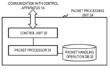
- FIG. 16 shows a configuration example of the packet processing unit 3A of the fourth exemplary embodiment.
- the packet processing unit 3A includes a communication unit 30, a packet processor 31, and a packet handling operation DB 32.
- the packet processor 31 On receiving a packet, the packet processor 31 searches for a packet handling operation corresponding to the received packet, from the packet handling operation DB 32. The packet processor 31 compares a matching rule of the packet handling operation and header information of the received packet, for example, and searches for a packet handling operation having a matching rule that matches the packet.
- the packet processor 31 processes packets in accordance with a processing method specified in the packet handling operation corresponding to the received packet.
- the packet processor 31 makes an enquiry for a packet handling operation corresponding to the received packet, with respect to the control apparatus.
- the assignment unit 2 forwards the enquiry received from the packet processing unit 3A to the control apparatus 1A assigned to the packet processing unit 3A.
- the assignment unit 2 for example, has a database that manages the control apparatus 1A assigned to the packet processing unit 3A.
- the assignment unit 2 for example, has a database that manages identification information and communication address (for example, IP address) of the control information assigned to the packet processing unit 3A.
- FIG. 17 is a sequence diagram showing an operational example of the fourth exemplary embodiment.
- FIG. 17 is an example, and operations of the fourth exemplary embodiment are not limited to FIG. 17.
- the assignment unit 2 assigns the control apparatus 1A to the packet processing unit 3A.
- the assignment unit 2 for example, determines the control apparatus 1A assigned to the packet processing unit 3A, based on a method illustrated in the second exemplary embodiment.
- the packet processing unit 3A makes an enquiry regarding a packet handling operation corresponding to a received packet, with respect to the assigned control apparatus 1A.
- the control apparatus 1A that receives the enquiry determines a packet handling operation and gives notification of the determined packet handling operation to the packet processing unit 3A.
- the packet processing unit 3A processes the packet in accordance with the notified packet handling operation.
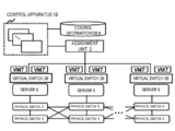
- FIG. 18 shows an example of a system configuration of a fifth exemplary embodiment.
- the system of the fifth exemplary embodiment includes a plurality of control apparatuses 1B, an assignment unit 2, a virtual switch (vSwitch) 3B, a server 5, a physical switch 6, and a virtual machine (VM) 7.
- vSwitch virtual switch
- VM virtual machine
- the virtual switch 3B is a network switch configured by software run by the server 5.
- the virtual switch 3B has a function corresponding to a packet processing unit 3 of the other exemplary embodiments. That is, the virtual switch 3B processes packets based on control by a control apparatus 1B. It is to be noted that the virtual switch 3B is positioned, for example, at an edge of a network configured by the physical switches 6.
- the plurality of control apparatuses 1B share a control information DB 4.
- the virtual machine (VM) 7 which is a computer configured by software, is run on the server 5.
- the virtual machine 7 communicates with another virtual machine 7 via the virtual switch 3B.
- the assignment unit 2 assigns the control apparatus 1B to the respective virtual switches 3B.
- the virtual switches 3B process a packet in accordance with a packet handling operation notified by the assigned control apparatus 1B.
- the server 5 is positioned at an edge of the network configured by the physical switches 6, for example.
- the control apparatus 1B controls operation of the virtual switch 3B present at the edge of the network.
- the virtual machine 7 communicates with another virtual machine 7 via the virtual network built on the physical switches 6.
- the virtual network for example, is built based on a protocol such as a VLAN (Virtual LAN) or NVGRE (Network Virtualization using Generic Routing Encapsulation).
- the virtual machine 7 communicates via the virtual network built on the physical switches 6.
- communication between virtual machine 7-1 and virtual machine 7-3 is executed via a tunnel for which a virtual network ID is "A”
- communication between virtual machine 7-2 and virtual machine 7-4 is executed via a tunnel for which a virtual network ID is "B”.
- the control apparatus 1B assigned to the virtual switch 3B-1 gives notification to the virtual switch 3B-1 of a packet handling operation specifying assigning a tag (for example, a VLAN tag) of the virtual network ID "A" to a packet with a destination of the virtual machine 7-3.
- a tag for example, a VLAN tag
- the virtual switch 3B-1 assigns the tag indicating the virtual network ID "A" to the packet, in accordance with an instruction of the control apparatus 1B.
- the control apparatus 1B assigned to the virtual switch 3B-2 gives notification to the virtual switch 3B-2 of a packet handling operation specifying assigning a tag (for example, a VLAN tag) of the virtual network ID "B" to a packet with a destination of the virtual machine 7-4.
- a tag for example, a VLAN tag
- the virtual switch 3B-2 assigns the tag indicating the virtual network ID "B" to the packet, in accordance with an instruction of the control apparatus 1B.
- the physical switch 6 holds in advance a configuration (for example, a port number with respect to which a packet with the virtual network ID "A" is to be forwarded) of a packet forwarding method based on the virtual network ID tag.
- control apparatus 1B controls only the virtual switch 3B, as in the fifth exemplary embodiment, it is possible to inhibit load increase on the control apparatus 1B. Furthermore, it is possible to install a network with centralized control by the control apparatuses, without replacing existing facilities (for example, the physical switches 6) of the communication system.
- a communication system comprising: a plurality of control apparatuses that determine a packet handling operation; a plurality of packet processing means that process a packet in accordance with the packet handling operation notified by said control apparatus; assignment means that assigns, with respect to each of the packet processing means concerned, a control apparatus that controls said packet processing means; and a database that is shared by said plurality of control apparatuses and that stores information related to said packet handling operation; wherein each of said control apparatuses refers to said database to determine said packet handling operation.
- Mode 2 The communication system according to mode 1, wherein each of said control apparatuses retrieves information corresponding to a packet processing means that is a target for control, from said database, and determines said packet handling operation to be transmitted to said packet processing means being the target for control, based on the retrieved information.
- Mode 3 The communication system according to mode 1 or 2, wherein each of said control apparatuses changes a reference region of said database, in accordance with a packet processing means that is a target for control, being changed.
- Mode 4 The communication system according to any of modes 1 to 3, wherein said database stores said information by division into regions respectively corresponding to said plurality of packet processing means.
- Mode 5 The communication system according to any of modes 1 to 4, wherein each of said control apparatuses refers to said database at prescribed periods, and confirms whether or not there is a packet handling operation to be notified to a packet processing means assigned by said assignment means.
- Mode 6 The communication system according to any of modes 1 to 5, wherein each of said control apparatuses refers to said database in response to receiving notification indicating that content of said database has been changed.
- Mode 7) The communication system according to any of modes 1 to 6, wherein said assignment means assigns, for each packet processing means, a control apparatus that controls the packet processing means concerned, based on a prescribed rule.
- Mode 8 The communication system according to any of modes 1 to 7, wherein said assignment means assigns, for each packet processing means, a control apparatus that controls the packet processing means concerned, based on load state of said control apparatus.
- Mode 9 The communication system according to any of modes 1 to 8, wherein said assignment means assigns, for each packet processing means, a control apparatus that controls the packet processing means concerned, based on information related to a position of said packet processing means concerned.
- Mode 10 The communication system according to any of modes 1 to 9, wherein said assignment means has a function for changing a control apparatus assigned to respective packet processing means to another control apparatus.
- Mode 11 The communication system according to any of modes 1 to 10, wherein said assignment means, in a case where a control apparatus has come to stop, determines another control apparatus to control a packet processing means in place of said stopped control apparatus.
- Mode 12 A control apparatus that controls packet processing, comprising: first means that refers to a database shared by said control apparatus and another control apparatus, and determines a packet handling operation related to a processing method for said packet; and second means that notifies said determined packet handling operation to, among a plurality of packet processing means, a packet processing means assigned to said control apparatus.
- Mode 13 The control apparatus according to mode 12, wherein said first means retrieves information corresponding to a packet processing means assigned to said control apparatus, from said database, and determines said packet handling operation to be transmitted to the packet processing means concerned, based on the retrieved information.
- Module 14 The control apparatus according to mode 12 or 13, wherein said first means changes a reference region of said database, in accordance with a packet processing means that is a target for control, being changed.
- Module 15 The control apparatus according to any of modes 12 to 14, wherein said database stores the information by division into regions respectively corresponding to said plurality of packet processing means.
- Mode 16 The control apparatus according to any of modes 12 to 15, wherein said control apparatus refers to said database at prescribed periods, and confirms whether or not there is a packet handling operation to be notified to a packet processing means assigned by a assignment means.
- Mode 17 The control apparatus according to any of modes 12 to 16, wherein said control apparatus refers to said database in response to receiving notification indicating that content of said database has been changed.
- Mode 18 A communication method by which a plurality of control apparatuses control packet processing, comprising: assigning, to each of a plurality of packet processing means, a control apparatus that controls the packet processing means concerned; determining, by each of said control apparatuses, a packet handling operation for processing a packet, by referring to a database shared by said plurality of control apparatuses; and notifying, by each of said control apparatuses, said determined packet handling operation to said assigned packet processing means.
- Mode 19 A control method for a control apparatus that controls processing of a packet, comprising: determining a packet handling operation related to a method of processing said packet, by referring to a database shared by said control apparatus and another control apparatus; and notifying said determined packet handling operation to, among a plurality of packet processing means, a packet processing means assigned to said control apparatus.
- Module 20 A program that executes, in a control apparatus that controls processing of a packet, a process of determining a packet handling operation related to a method of processing said packet, by referring to a database shared by said control apparatus and another control apparatus; and a process of notifying said determined packet handling operation to, among a plurality of packet processing means, a packet processing means assigned to said control apparatus.
Abstract
Description
The present invention is based upon and claims the benefit of priority of Japanese Patent Application No. 2012-135031, filed on June 14, 2012, the disclosure of which is incorporated herein in its entirety by reference thereto.
The present invention relates to a communication system, a control apparatus, a communication method, a control method and program, and relates to a communication system, a control apparatus, a communication method, a control method and program that process packets in accordance with control by the control apparatus.
FIG. 1 shows a configuration example of a communication system of a first exemplary embodiment. FIG. 1 is an example, and the configuration of the communication system of the present disclosure is not limited to FIG. 1.
(Second Exemplary Embodiment)
A configuration example of a communication system in a second exemplary embodiment is similar to FIG. 1.
(Third Exemplary Embodiment)
FIG. 10 shows a configuration example of a control
(Fourth Exemplary Embodiment)
A fourth exemplary embodiment illustrates an example in which the present disclosure is implemented by improving technology known as OpenFlow that has a centralized control architecture.
(Fifth Exemplary Embodiment)
FIG. 18 shows an example of a system configuration of a fifth exemplary embodiment.
(Mode 1)
A communication system, comprising:
a plurality of control apparatuses that determine a packet handling operation;
a plurality of packet processing means that process a packet in accordance with the packet handling operation notified by said control apparatus;
assignment means that assigns, with respect to each of the packet processing means concerned, a control apparatus that controls said packet processing means; and
a database that is shared by said plurality of control apparatuses and that stores information related to said packet handling operation; wherein
each of said control apparatuses refers to said database to determine said packet handling operation.
(Mode 2)
The communication system according to
(Mode 3)
The communication system according to
(Mode 4)
The communication system according to any of
(Mode 5)
The communication system according to any of
(Mode 6)
The communication system according to any of
(Mode 7)
The communication system according to any of
(Mode 8)
The communication system according to any of
(Mode 9)
The communication system according to any of
(Mode 10)
The communication system according to any of
(Mode 11)
The communication system according to any of
(Mode 12)
A control apparatus that controls packet processing, comprising:
first means that refers to a database shared by said control apparatus and another control apparatus, and determines a packet handling operation related to a processing method for said packet; and
second means that notifies said determined packet handling operation to, among a plurality of packet processing means, a packet processing means assigned to said control apparatus.
(Mode 13)
The control apparatus according to
(Mode 14)
The control apparatus according to
(Mode 15)
The control apparatus according to any of
(Mode 16)
The control apparatus according to any of
(Mode 17)
The control apparatus according to any of
(Mode 18)
A communication method by which a plurality of control apparatuses control packet processing, comprising:
assigning, to each of a plurality of packet processing means, a control apparatus that controls the packet processing means concerned;
determining, by each of said control apparatuses, a packet handling operation for processing a packet, by referring to a database shared by said plurality of control apparatuses; and
notifying, by each of said control apparatuses, said determined packet handling operation to said assigned packet processing means.
(Mode 19)
A control method for a control apparatus that controls processing of a packet, comprising:
determining a packet handling operation related to a method of processing said packet, by referring to a database shared by said control apparatus and another control apparatus; and
notifying said determined packet handling operation to, among a plurality of packet processing means, a packet processing means assigned to said control apparatus.
(Mode 20)
A program that executes, in a control apparatus that controls processing of a packet,
a process of determining a packet handling operation related to a method of processing said packet, by referring to a database shared by said control apparatus and another control apparatus; and
a process of notifying said determined packet handling operation to, among a plurality of packet processing means, a packet processing means assigned to said control apparatus.
10 communication unit
11, 20 control unit
12 assignment management DB
2 assignment unit
21 management DB
3, 3A packet processing unit
3B virtual switch
30 communication unit
31 packet processor
32 packet handling operation DB
4 control information DB
5 server
6 physical switch
7 virtual machine (VM)
600 OpenFlow switch
601 flow table
700 OpenFlow controller
701 secure channel
Claims (20)
- A communication system, comprising:
a plurality of control apparatuses that determine a packet handling operation;
a plurality of packet processing means that process a packet in accordance with the packet handling operation notified by said control apparatus;
assignment means that assigns, with respect to each of said packet processing means, a control apparatus that controls the packet processing means concerned; and
a database that is shared by said plurality of control apparatuses and that stores information related to said packet handling operation; wherein
each of said control apparatuses refers to said database to determine said packet handling operation. - The communication system according to claim 1, wherein each of said control apparatuses retrieves information corresponding to a packet processing means that is a target for control, from said database, and determines said packet handling operation to be transmitted to said packet processing means being the target for control, based on the retrieved information.
- The communication system according to claim 1 or 2, wherein each of said control apparatuses changes a reference region of said database, in accordance with a packet processing means that is a target for control, being changed.
- The communication system according to any of claims 1 to 3, wherein said database stores said information by division into regions respectively corresponding to said plurality of packet processing means.
- The communication system according to any of claims 1 to 4, wherein each of said control apparatuses refers to said database at prescribed periods, and confirms whether or not there is a packet handling operation to be notified to a packet processing means assigned by said assignment means.
- The communication system according to any of claims 1 to 5, wherein each of said control apparatuses refers to said database in response to receiving notification indicating that content of said database has been changed.
- The communication system according to any of claims 1 to 6, wherein said assignment means assigns, for each packet processing means, a control apparatus that controls the packet processing means concerned, based on a prescribed rule.
- The communication system according to any of claims 1 to 7, wherein said assignment means assigns, for each packet processing means, a control apparatus that controls the packet processing means concerned, based on load state of said control apparatus.
- The communication system according to any of claims 1 to 8, wherein said assignment means assigns, for each packet processing means, a control apparatus that controls the packet processing means concerned, based on information related to a position of said packet processing means.
- The communication system according to any of claims 1 to 9, wherein said assignment means has a function for changing a control apparatus assigned to respective packet processing means to another control apparatus.
- The communication system according to any of claims 1 to 10, wherein said assignment means, in a case where a control apparatus has come to stop, determines another control apparatus to control a packet processing means in place of said stopped control apparatus.
- A control apparatus that controls packet processing, comprising:
first means that refers to a database shared by said control apparatus and another control apparatus, and determines a packet handling operation related to a processing method for said packet; and
second means that notifies said determined packet handling operation to, among a plurality of packet processing means, a packet processing means assigned to said control apparatus. - The control apparatus according to claim 12, wherein said first means retrieves information corresponding to a packet processing means assigned to said control apparatus, from said database, and determines said packet handling operation to be transmitted to the packet processing means concerned, based on the retrieved information.
- The control apparatus according to claim 12 or 13, wherein said first means changes a reference region of said database, in accordance with a packet processing means that is a target for control, being changed.
- The control apparatus according to any of claims 12 to 14, wherein said database stores the information by division into regions respectively corresponding to said plurality of packet processing means.
- The control apparatus according to any of claims 12 to 15, wherein said control apparatus refers to said database at prescribed periods, and confirms whether or not there is a packet handling operation to be notified to a packet processing means assigned by a assignment means.
- The control apparatus according to any of claims 12 to 16, wherein said control apparatus refers to said database in response to receiving notification indicating that content of said database has been changed.
- A communication method by which a plurality of control apparatuses control packet processing, comprising:
assigning, to each of a plurality of packet processing means, a control apparatus that controls the packet processing means concerned;
determining, by each of said control apparatuses, a packet handling operation for processing a packet, by referring to a database shared by said plurality of control apparatuses; and
notifying, by each of said control apparatuses, said determined packet handling operation to said assigned packet processing means. - A control method for a control apparatus that controls processing of a packet, comprising:
determining a packet handling operation related to a method of processing said packet, by referring to a database shared by said control apparatus and another control apparatus; and
notifying said determined packet handling operation to, among a plurality of packet processing means, a packet processing means assigned to said control apparatus. - A program that executes, in a control apparatus that controls processing of a packet,
a process of determining a packet handling operation related to a method of processing said packet, by referring to a database shared by said control apparatus and another control apparatus; and
a process of notifying said determined packet handling operation to, among a plurality of packet processing means, a packet processing means assigned to said control apparatus.
Priority Applications (7)
| Application Number | Priority Date | Filing Date | Title |
|---|---|---|---|
| KR1020147034165A KR20150016314A (en) | 2012-06-14 | 2013-06-12 | Communication system, control apparatus, communication method, control method and program |
| JP2014560154A JP6323339B2 (en) | 2012-06-14 | 2013-06-12 | COMMUNICATION SYSTEM, CONTROL DEVICE, COMMUNICATION METHOD, CONTROL METHOD, AND PROGRAM |
| CN201380030383.0A CN104365069A (en) | 2012-06-14 | 2013-06-12 | Communication system, control apparatus, communication method, control method and program |
| EP13803867.4A EP2862322B1 (en) | 2012-06-14 | 2013-06-12 | Communication system, control apparatus, communication method, control method and program |
| IN10624DEN2014 IN2014DN10624A (en) | 2012-06-14 | 2013-06-12 | |
| US14/407,434 US10212084B2 (en) | 2012-06-14 | 2013-06-12 | Communication system, control apparatus, communication method, control method and program |
| HK15109019.1A HK1208572A1 (en) | 2012-06-14 | 2015-09-15 | Communication system, control apparatus, communication method, control method and program |
Applications Claiming Priority (2)
| Application Number | Priority Date | Filing Date | Title |
|---|---|---|---|
| JP2012-135031 | 2012-06-14 | ||
| JP2012135031 | 2012-06-14 |
Publications (1)
| Publication Number | Publication Date |
|---|---|
| WO2013187054A1 true WO2013187054A1 (en) | 2013-12-19 |
Family
ID=49757899
Family Applications (1)
| Application Number | Title | Priority Date | Filing Date |
|---|---|---|---|
| PCT/JP2013/003673 WO2013187054A1 (en) | 2012-06-14 | 2013-06-12 | Communication system, control apparatus, communication method, control method and program |
Country Status (8)
| Country | Link |
|---|---|
| US (1) | US10212084B2 (en) |
| EP (1) | EP2862322B1 (en) |
| JP (1) | JP6323339B2 (en) |
| KR (1) | KR20150016314A (en) |
| CN (1) | CN104365069A (en) |
| HK (1) | HK1208572A1 (en) |
| IN (1) | IN2014DN10624A (en) |
| WO (1) | WO2013187054A1 (en) |
Cited By (3)
| Publication number | Priority date | Publication date | Assignee | Title |
|---|---|---|---|---|
| WO2015105987A1 (en) | 2014-01-10 | 2015-07-16 | Huawei Technologies Co., Ltd. | System and method for zoning in software defined networks |
| CN106464586A (en) * | 2014-03-06 | 2017-02-22 | 日本电气株式会社 | Communication system, control device, communication device, and communication method |
| KR20170091671A (en) * | 2014-12-05 | 2017-08-09 | 후아웨이 테크놀러지 컴퍼니 리미티드 | Systems and methods for placing virtual serving gateways for mobility management |
Families Citing this family (4)
| Publication number | Priority date | Publication date | Assignee | Title |
|---|---|---|---|---|
| JP6787475B2 (en) | 2016-07-21 | 2020-11-18 | 日本電気株式会社 | Communication equipment, systems, rollback methods and programs |
| JP6543600B2 (en) * | 2016-08-17 | 2019-07-10 | 日本電信電話株式会社 | Management system and management method |
| CN107592226A (en) * | 2017-09-15 | 2018-01-16 | 厦门拓宝科技有限公司 | The centralized management method of a variety of distinct device types |
| JP7003864B2 (en) * | 2018-07-24 | 2022-02-10 | 日本電信電話株式会社 | Sorting device, communication system and sorting method |
Citations (6)
| Publication number | Priority date | Publication date | Assignee | Title |
|---|---|---|---|---|
| JP2005236881A (en) * | 2004-02-23 | 2005-09-02 | Nippon Telegr & Teleph Corp <Ntt> | Bgp path information management system and program thereof |
| WO2008095010A1 (en) | 2007-02-01 | 2008-08-07 | The Board Of Trustees Of The Leland Stanford Jr. University | Secure network switching infrastructure |
| JP2009213097A (en) * | 2008-03-06 | 2009-09-17 | Nippon Telegr & Teleph Corp <Ntt> | Information recording system and information recording method |
| JP2010045503A (en) * | 2008-08-11 | 2010-02-25 | Nippon Telegr & Teleph Corp <Ntt> | Packet transfer system and packet transfer method |
| WO2011065268A1 (en) * | 2009-11-26 | 2011-06-03 | 日本電気株式会社 | Load distribution system, load distribution method, and program |
| JP2012080516A (en) * | 2010-09-06 | 2012-04-19 | Nippon Telegraph & Telephone West Corp | Method for realizing virtual system operation and communication device |
Family Cites Families (9)
| Publication number | Priority date | Publication date | Assignee | Title |
|---|---|---|---|---|
| JP2006227963A (en) * | 2005-02-18 | 2006-08-31 | Fujitsu Ltd | Multistage load balancer and its method and program |
| US7536481B2 (en) * | 2005-02-25 | 2009-05-19 | Microsoft Corporation | Method and system for re-synchronizing end points when an intermediary detects that the end points may be unsynchronized |
| CN100389392C (en) * | 2006-05-29 | 2008-05-21 | 杭州华三通信技术有限公司 | Method for realizing load uniform in clustering system, system and storage controller |
| EP2553901B1 (en) * | 2010-03-26 | 2016-04-27 | Citrix Systems, Inc. | System and method for link load balancing on a multi-core device |
| US9001827B2 (en) * | 2010-12-17 | 2015-04-07 | Big Switch Networks, Inc. | Methods for configuring network switches |
| US9185056B2 (en) * | 2011-09-20 | 2015-11-10 | Big Switch Networks, Inc. | System and methods for controlling network traffic through virtual switches |
| US8705536B2 (en) * | 2012-03-05 | 2014-04-22 | Telefonaktiebolaget L M Ericsson (Publ) | Methods of operating forwarding elements including shadow tables and related forwarding elements |
| US8730806B2 (en) * | 2012-04-03 | 2014-05-20 | Telefonaktiebolaget L M Ericsson (Publ) | Congestion control and resource allocation in split architecture networks |
| US8908539B1 (en) * | 2012-05-25 | 2014-12-09 | Google Inc. | Systems and methods for testing network connections of a centrally-controlled network |
-
2013
- 2013-06-12 JP JP2014560154A patent/JP6323339B2/en active Active
- 2013-06-12 WO PCT/JP2013/003673 patent/WO2013187054A1/en active Application Filing
- 2013-06-12 IN IN10624DEN2014 patent/IN2014DN10624A/en unknown
- 2013-06-12 CN CN201380030383.0A patent/CN104365069A/en active Pending
- 2013-06-12 US US14/407,434 patent/US10212084B2/en active Active
- 2013-06-12 EP EP13803867.4A patent/EP2862322B1/en active Active
- 2013-06-12 KR KR1020147034165A patent/KR20150016314A/en not_active Application Discontinuation
-
2015
- 2015-09-15 HK HK15109019.1A patent/HK1208572A1/en unknown
Patent Citations (6)
| Publication number | Priority date | Publication date | Assignee | Title |
|---|---|---|---|---|
| JP2005236881A (en) * | 2004-02-23 | 2005-09-02 | Nippon Telegr & Teleph Corp <Ntt> | Bgp path information management system and program thereof |
| WO2008095010A1 (en) | 2007-02-01 | 2008-08-07 | The Board Of Trustees Of The Leland Stanford Jr. University | Secure network switching infrastructure |
| JP2009213097A (en) * | 2008-03-06 | 2009-09-17 | Nippon Telegr & Teleph Corp <Ntt> | Information recording system and information recording method |
| JP2010045503A (en) * | 2008-08-11 | 2010-02-25 | Nippon Telegr & Teleph Corp <Ntt> | Packet transfer system and packet transfer method |
| WO2011065268A1 (en) * | 2009-11-26 | 2011-06-03 | 日本電気株式会社 | Load distribution system, load distribution method, and program |
| JP2012080516A (en) * | 2010-09-06 | 2012-04-19 | Nippon Telegraph & Telephone West Corp | Method for realizing virtual system operation and communication device |
Non-Patent Citations (3)
| Title |
|---|
| ROB SHERWOOD, FLOWVISOR: A NETWORK VIRTUALIZATION LAYER, 28 May 2012 (2012-05-28), Retrieved from the Internet <URL:http://www.openflow.orq/downloads/technicalreports/openflow-tr-2009-1-flowvisor.pdf> |
| See also references of EP2862322A4 |
| TEEMU KOPONEN ET AL.: "Onix: A Distributed Control Platform for Large-scale Production Networks", USENIX, 23 September 2010 (2010-09-23), pages 1 - 14, XP061010918 |
Cited By (12)
| Publication number | Priority date | Publication date | Assignee | Title |
|---|---|---|---|---|
| WO2015105987A1 (en) | 2014-01-10 | 2015-07-16 | Huawei Technologies Co., Ltd. | System and method for zoning in software defined networks |
| CN105900403A (en) * | 2014-01-10 | 2016-08-24 | 华为技术有限公司 | System and method for zoning in software defined networks |
| KR20160105469A (en) * | 2014-01-10 | 2016-09-06 | 후아웨이 테크놀러지 컴퍼니 리미티드 | System and method for zoning in software defined networks |
| EP3092779A4 (en) * | 2014-01-10 | 2016-12-28 | Huawei Tech Co Ltd | System and method for zoning in software defined networks |
| JP2017504265A (en) * | 2014-01-10 | 2017-02-02 | ホアウェイ・テクノロジーズ・カンパニー・リミテッド | System and method for zoning in a software defined network |
| AU2015204758B2 (en) * | 2014-01-10 | 2017-09-07 | Huawei Technologies Co., Ltd. | System and method for zoning in software defined networks |
| KR101908466B1 (en) * | 2014-01-10 | 2018-10-16 | 후아웨이 테크놀러지 컴퍼니 리미티드 | System and method for zoning in software defined networks |
| CN105900403B (en) * | 2014-01-10 | 2019-10-22 | 华为技术有限公司 | Partition system and method in software defined network |
| CN106464586A (en) * | 2014-03-06 | 2017-02-22 | 日本电气株式会社 | Communication system, control device, communication device, and communication method |
| KR20170091671A (en) * | 2014-12-05 | 2017-08-09 | 후아웨이 테크놀러지 컴퍼니 리미티드 | Systems and methods for placing virtual serving gateways for mobility management |
| US9860758B2 (en) | 2014-12-05 | 2018-01-02 | Huawei Technologies Co., Ltd. | Systems and methods for placing virtual serving gateways for mobility management |
| KR101943530B1 (en) * | 2014-12-05 | 2019-01-29 | 후아웨이 테크놀러지 컴퍼니 리미티드 | Systems and methods for placing virtual serving gateways for mobility management |
Also Published As
| Publication number | Publication date |
|---|---|
| CN104365069A (en) | 2015-02-18 |
| HK1208572A1 (en) | 2016-03-04 |
| IN2014DN10624A (en) | 2015-09-11 |
| JP6323339B2 (en) | 2018-05-16 |
| EP2862322A4 (en) | 2016-01-20 |
| US10212084B2 (en) | 2019-02-19 |
| JP2015519765A (en) | 2015-07-09 |
| EP2862322B1 (en) | 2019-10-02 |
| US20150156113A1 (en) | 2015-06-04 |
| EP2862322A1 (en) | 2015-04-22 |
| KR20150016314A (en) | 2015-02-11 |
Similar Documents
| Publication | Publication Date | Title |
|---|---|---|
| US10212084B2 (en) | Communication system, control apparatus, communication method, control method and program | |
| US10237179B2 (en) | Systems and methods of inter data center out-bound traffic management | |
| US9379975B2 (en) | Communication control system, control server, forwarding node, communication control method, and communication control program | |
| JP5637148B2 (en) | Switch network system, controller, and control method | |
| JP5850068B2 (en) | Control device, communication system, communication method, and program | |
| JP5585660B2 (en) | Communication system, control device, processing rule setting method and program | |
| US20120170477A1 (en) | Computer, communication system, network connection switching method, and program | |
| US20140241367A1 (en) | Communication system, controller, communication method, and program | |
| US10263809B2 (en) | Selecting an optimal network device for reporting flow table misses upon expiry of a flow in a software defined network | |
| JP2010050749A (en) | Routing control system | |
| US20180077048A1 (en) | Controller, control method and program | |
| JPWO2016157864A1 (en) | Network system, network control method, and control apparatus | |
| US20150341267A1 (en) | Control apparatus, communication apparatus, communication system, switch control method, and program | |
| WO2013186825A1 (en) | Computer system, communication control server, communication control method, and program | |
| JP6011619B2 (en) | Mobile communication terminal, communication method, communication system, and control apparatus | |
| KR20160003762A (en) | Communication node, communication system, packet processing method and program | |
| WO2014133025A1 (en) | Communication system, host controller, network control method, and program | |
| US9749240B2 (en) | Communication system, virtual machine server, virtual network management apparatus, network control method, and program | |
| US20150381775A1 (en) | Communication system, communication method, control apparatus, control apparatus control method, and program | |
| WO2015133561A1 (en) | Communication system, control device, communication device, and communication method | |
| JP6292128B2 (en) | COMMUNICATION SYSTEM, NODE, CONTROL DEVICE, COMMUNICATION METHOD, AND PROGRAM | |
| CN107534621B (en) | Memory system, memory component device, routing method, and readable storage medium | |
| WO2014123194A1 (en) | Communication system, control apparatus, communication control method and program | |
| JP2016192660A (en) | Network system, network control method, control device, and operation management device | |
| US9860178B2 (en) | Control message relay apparatus, control message relay method, and program |
Legal Events
| Date | Code | Title | Description |
|---|---|---|---|
| 121 | Ep: the epo has been informed by wipo that ep was designated in this application |
Ref document number: 13803867 Country of ref document: EP Kind code of ref document: A1 |
|
| ENP | Entry into the national phase |
Ref document number: 20147034165 Country of ref document: KR Kind code of ref document: A |
|
| WWE | Wipo information: entry into national phase |
Ref document number: 14407434 Country of ref document: US |
|
| ENP | Entry into the national phase |
Ref document number: 2014560154 Country of ref document: JP Kind code of ref document: A |
|
| NENP | Non-entry into the national phase |
Ref country code: DE |
|
| WWE | Wipo information: entry into national phase |
Ref document number: 2013803867 Country of ref document: EP |