EP2861505B1 - Rohrförmiger stumpfgeschweisster verpackungskörper - Google Patents
Rohrförmiger stumpfgeschweisster verpackungskörper Download PDFInfo
- Publication number
- EP2861505B1 EP2861505B1 EP13744830.4A EP13744830A EP2861505B1 EP 2861505 B1 EP2861505 B1 EP 2861505B1 EP 13744830 A EP13744830 A EP 13744830A EP 2861505 B1 EP2861505 B1 EP 2861505B1
- Authority
- EP
- European Patent Office
- Prior art keywords
- reinforcing element
- tubular body
- film
- layer
- body according
- Prior art date
- Legal status (The legal status is an assumption and is not a legal conclusion. Google has not performed a legal analysis and makes no representation as to the accuracy of the status listed.)
- Active
Links
Images

Classifications
-
- B—PERFORMING OPERATIONS; TRANSPORTING
- B65—CONVEYING; PACKING; STORING; HANDLING THIN OR FILAMENTARY MATERIAL
- B65D—CONTAINERS FOR STORAGE OR TRANSPORT OF ARTICLES OR MATERIALS, e.g. BAGS, BARRELS, BOTTLES, BOXES, CANS, CARTONS, CRATES, DRUMS, JARS, TANKS, HOPPERS, FORWARDING CONTAINERS; ACCESSORIES, CLOSURES, OR FITTINGS THEREFOR; PACKAGING ELEMENTS; PACKAGES
- B65D75/00—Packages comprising articles or materials partially or wholly enclosed in strips, sheets, blanks, tubes, or webs of flexible sheet material, e.g. in folded wrappers
- B65D75/04—Articles or materials wholly enclosed in single sheets or wrapper blanks
- B65D75/06—Articles or materials wholly enclosed in single sheets or wrapper blanks in sheets or blanks initially folded to form tubes
-
- B—PERFORMING OPERATIONS; TRANSPORTING
- B29—WORKING OF PLASTICS; WORKING OF SUBSTANCES IN A PLASTIC STATE IN GENERAL
- B29C—SHAPING OR JOINING OF PLASTICS; SHAPING OF MATERIAL IN A PLASTIC STATE, NOT OTHERWISE PROVIDED FOR; AFTER-TREATMENT OF THE SHAPED PRODUCTS, e.g. REPAIRING
- B29C66/00—General aspects of processes or apparatus for joining preformed parts
- B29C66/01—General aspects dealing with the joint area or with the area to be joined
- B29C66/05—Particular design of joint configurations
- B29C66/10—Particular design of joint configurations particular design of the joint cross-sections
- B29C66/11—Joint cross-sections comprising a single joint-segment, i.e. one of the parts to be joined comprising a single joint-segment in the joint cross-section
- B29C66/114—Single butt joints
- B29C66/1142—Single butt to butt joints
-
- B—PERFORMING OPERATIONS; TRANSPORTING
- B29—WORKING OF PLASTICS; WORKING OF SUBSTANCES IN A PLASTIC STATE IN GENERAL
- B29C—SHAPING OR JOINING OF PLASTICS; SHAPING OF MATERIAL IN A PLASTIC STATE, NOT OTHERWISE PROVIDED FOR; AFTER-TREATMENT OF THE SHAPED PRODUCTS, e.g. REPAIRING
- B29C65/00—Joining or sealing of preformed parts, e.g. welding of plastics materials; Apparatus therefor
- B29C65/48—Joining or sealing of preformed parts, e.g. welding of plastics materials; Apparatus therefor using adhesives, i.e. using supplementary joining material; solvent bonding
- B29C65/50—Joining or sealing of preformed parts, e.g. welding of plastics materials; Apparatus therefor using adhesives, i.e. using supplementary joining material; solvent bonding using adhesive tape, e.g. thermoplastic tape; using threads or the like
- B29C65/5042—Joining or sealing of preformed parts, e.g. welding of plastics materials; Apparatus therefor using adhesives, i.e. using supplementary joining material; solvent bonding using adhesive tape, e.g. thermoplastic tape; using threads or the like covering both elements to be joined
-
- B—PERFORMING OPERATIONS; TRANSPORTING
- B29—WORKING OF PLASTICS; WORKING OF SUBSTANCES IN A PLASTIC STATE IN GENERAL
- B29C—SHAPING OR JOINING OF PLASTICS; SHAPING OF MATERIAL IN A PLASTIC STATE, NOT OTHERWISE PROVIDED FOR; AFTER-TREATMENT OF THE SHAPED PRODUCTS, e.g. REPAIRING
- B29C65/00—Joining or sealing of preformed parts, e.g. welding of plastics materials; Apparatus therefor
- B29C65/48—Joining or sealing of preformed parts, e.g. welding of plastics materials; Apparatus therefor using adhesives, i.e. using supplementary joining material; solvent bonding
- B29C65/50—Joining or sealing of preformed parts, e.g. welding of plastics materials; Apparatus therefor using adhesives, i.e. using supplementary joining material; solvent bonding using adhesive tape, e.g. thermoplastic tape; using threads or the like
- B29C65/5064—Joining or sealing of preformed parts, e.g. welding of plastics materials; Apparatus therefor using adhesives, i.e. using supplementary joining material; solvent bonding using adhesive tape, e.g. thermoplastic tape; using threads or the like of particular form, e.g. being C-shaped, T-shaped
- B29C65/5071—Joining or sealing of preformed parts, e.g. welding of plastics materials; Apparatus therefor using adhesives, i.e. using supplementary joining material; solvent bonding using adhesive tape, e.g. thermoplastic tape; using threads or the like of particular form, e.g. being C-shaped, T-shaped and being composed by one single element
-
- B—PERFORMING OPERATIONS; TRANSPORTING
- B29—WORKING OF PLASTICS; WORKING OF SUBSTANCES IN A PLASTIC STATE IN GENERAL
- B29C—SHAPING OR JOINING OF PLASTICS; SHAPING OF MATERIAL IN A PLASTIC STATE, NOT OTHERWISE PROVIDED FOR; AFTER-TREATMENT OF THE SHAPED PRODUCTS, e.g. REPAIRING
- B29C66/00—General aspects of processes or apparatus for joining preformed parts
- B29C66/40—General aspects of joining substantially flat articles, e.g. plates, sheets or web-like materials; Making flat seams in tubular or hollow articles; Joining single elements to substantially flat surfaces
- B29C66/41—Joining substantially flat articles ; Making flat seams in tubular or hollow articles
- B29C66/43—Joining a relatively small portion of the surface of said articles
- B29C66/432—Joining a relatively small portion of the surface of said articles for making tubular articles or closed loops, e.g. by joining several sheets ; for making hollow articles or hollow preforms
- B29C66/4322—Joining a relatively small portion of the surface of said articles for making tubular articles or closed loops, e.g. by joining several sheets ; for making hollow articles or hollow preforms by joining a single sheet to itself
-
- B—PERFORMING OPERATIONS; TRANSPORTING
- B29—WORKING OF PLASTICS; WORKING OF SUBSTANCES IN A PLASTIC STATE IN GENERAL
- B29C—SHAPING OR JOINING OF PLASTICS; SHAPING OF MATERIAL IN A PLASTIC STATE, NOT OTHERWISE PROVIDED FOR; AFTER-TREATMENT OF THE SHAPED PRODUCTS, e.g. REPAIRING
- B29C66/00—General aspects of processes or apparatus for joining preformed parts
- B29C66/70—General aspects of processes or apparatus for joining preformed parts characterised by the composition, physical properties or the structure of the material of the parts to be joined; Joining with non-plastics material
- B29C66/72—General aspects of processes or apparatus for joining preformed parts characterised by the composition, physical properties or the structure of the material of the parts to be joined; Joining with non-plastics material characterised by the structure of the material of the parts to be joined
- B29C66/723—General aspects of processes or apparatus for joining preformed parts characterised by the composition, physical properties or the structure of the material of the parts to be joined; Joining with non-plastics material characterised by the structure of the material of the parts to be joined being multi-layered
- B29C66/7232—General aspects of processes or apparatus for joining preformed parts characterised by the composition, physical properties or the structure of the material of the parts to be joined; Joining with non-plastics material characterised by the structure of the material of the parts to be joined being multi-layered comprising a non-plastics layer
- B29C66/72321—General aspects of processes or apparatus for joining preformed parts characterised by the composition, physical properties or the structure of the material of the parts to be joined; Joining with non-plastics material characterised by the structure of the material of the parts to be joined being multi-layered comprising a non-plastics layer consisting of metals or their alloys
-
- B—PERFORMING OPERATIONS; TRANSPORTING
- B65—CONVEYING; PACKING; STORING; HANDLING THIN OR FILAMENTARY MATERIAL
- B65D—CONTAINERS FOR STORAGE OR TRANSPORT OF ARTICLES OR MATERIALS, e.g. BAGS, BARRELS, BOTTLES, BOXES, CANS, CARTONS, CRATES, DRUMS, JARS, TANKS, HOPPERS, FORWARDING CONTAINERS; ACCESSORIES, CLOSURES, OR FITTINGS THEREFOR; PACKAGING ELEMENTS; PACKAGES
- B65D35/00—Pliable tubular containers adapted to be permanently or temporarily deformed to expel contents, e.g. collapsible tubes for toothpaste or other plastic or semi-liquid material; Holders therefor
- B65D35/02—Body construction
-
- B—PERFORMING OPERATIONS; TRANSPORTING
- B29—WORKING OF PLASTICS; WORKING OF SUBSTANCES IN A PLASTIC STATE IN GENERAL
- B29C—SHAPING OR JOINING OF PLASTICS; SHAPING OF MATERIAL IN A PLASTIC STATE, NOT OTHERWISE PROVIDED FOR; AFTER-TREATMENT OF THE SHAPED PRODUCTS, e.g. REPAIRING
- B29C65/00—Joining or sealing of preformed parts, e.g. welding of plastics materials; Apparatus therefor
- B29C65/48—Joining or sealing of preformed parts, e.g. welding of plastics materials; Apparatus therefor using adhesives, i.e. using supplementary joining material; solvent bonding
- B29C65/4805—Joining or sealing of preformed parts, e.g. welding of plastics materials; Apparatus therefor using adhesives, i.e. using supplementary joining material; solvent bonding characterised by the type of adhesives
- B29C65/481—Non-reactive adhesives, e.g. physically hardening adhesives
- B29C65/4815—Hot melt adhesives, e.g. thermoplastic adhesives
-
- B—PERFORMING OPERATIONS; TRANSPORTING
- B29—WORKING OF PLASTICS; WORKING OF SUBSTANCES IN A PLASTIC STATE IN GENERAL
- B29C—SHAPING OR JOINING OF PLASTICS; SHAPING OF MATERIAL IN A PLASTIC STATE, NOT OTHERWISE PROVIDED FOR; AFTER-TREATMENT OF THE SHAPED PRODUCTS, e.g. REPAIRING
- B29C66/00—General aspects of processes or apparatus for joining preformed parts
- B29C66/70—General aspects of processes or apparatus for joining preformed parts characterised by the composition, physical properties or the structure of the material of the parts to be joined; Joining with non-plastics material
- B29C66/71—General aspects of processes or apparatus for joining preformed parts characterised by the composition, physical properties or the structure of the material of the parts to be joined; Joining with non-plastics material characterised by the composition of the plastics material of the parts to be joined
-
- B—PERFORMING OPERATIONS; TRANSPORTING
- B29—WORKING OF PLASTICS; WORKING OF SUBSTANCES IN A PLASTIC STATE IN GENERAL
- B29C—SHAPING OR JOINING OF PLASTICS; SHAPING OF MATERIAL IN A PLASTIC STATE, NOT OTHERWISE PROVIDED FOR; AFTER-TREATMENT OF THE SHAPED PRODUCTS, e.g. REPAIRING
- B29C66/00—General aspects of processes or apparatus for joining preformed parts
- B29C66/70—General aspects of processes or apparatus for joining preformed parts characterised by the composition, physical properties or the structure of the material of the parts to be joined; Joining with non-plastics material
- B29C66/72—General aspects of processes or apparatus for joining preformed parts characterised by the composition, physical properties or the structure of the material of the parts to be joined; Joining with non-plastics material characterised by the structure of the material of the parts to be joined
- B29C66/723—General aspects of processes or apparatus for joining preformed parts characterised by the composition, physical properties or the structure of the material of the parts to be joined; Joining with non-plastics material characterised by the structure of the material of the parts to be joined being multi-layered
- B29C66/7234—General aspects of processes or apparatus for joining preformed parts characterised by the composition, physical properties or the structure of the material of the parts to be joined; Joining with non-plastics material characterised by the structure of the material of the parts to be joined being multi-layered comprising a barrier layer
-
- B—PERFORMING OPERATIONS; TRANSPORTING
- B29—WORKING OF PLASTICS; WORKING OF SUBSTANCES IN A PLASTIC STATE IN GENERAL
- B29C—SHAPING OR JOINING OF PLASTICS; SHAPING OF MATERIAL IN A PLASTIC STATE, NOT OTHERWISE PROVIDED FOR; AFTER-TREATMENT OF THE SHAPED PRODUCTS, e.g. REPAIRING
- B29C66/00—General aspects of processes or apparatus for joining preformed parts
- B29C66/70—General aspects of processes or apparatus for joining preformed parts characterised by the composition, physical properties or the structure of the material of the parts to be joined; Joining with non-plastics material
- B29C66/73—General aspects of processes or apparatus for joining preformed parts characterised by the composition, physical properties or the structure of the material of the parts to be joined; Joining with non-plastics material characterised by the intensive physical properties of the material of the parts to be joined, by the optical properties of the material of the parts to be joined, by the extensive physical properties of the parts to be joined, by the state of the material of the parts to be joined or by the material of the parts to be joined being a thermoplastic or a thermoset
- B29C66/737—General aspects of processes or apparatus for joining preformed parts characterised by the composition, physical properties or the structure of the material of the parts to be joined; Joining with non-plastics material characterised by the intensive physical properties of the material of the parts to be joined, by the optical properties of the material of the parts to be joined, by the extensive physical properties of the parts to be joined, by the state of the material of the parts to be joined or by the material of the parts to be joined being a thermoplastic or a thermoset characterised by the state of the material of the parts to be joined
- B29C66/7371—General aspects of processes or apparatus for joining preformed parts characterised by the composition, physical properties or the structure of the material of the parts to be joined; Joining with non-plastics material characterised by the intensive physical properties of the material of the parts to be joined, by the optical properties of the material of the parts to be joined, by the extensive physical properties of the parts to be joined, by the state of the material of the parts to be joined or by the material of the parts to be joined being a thermoplastic or a thermoset characterised by the state of the material of the parts to be joined oriented or heat-shrinkable
- B29C66/73711—General aspects of processes or apparatus for joining preformed parts characterised by the composition, physical properties or the structure of the material of the parts to be joined; Joining with non-plastics material characterised by the intensive physical properties of the material of the parts to be joined, by the optical properties of the material of the parts to be joined, by the extensive physical properties of the parts to be joined, by the state of the material of the parts to be joined or by the material of the parts to be joined being a thermoplastic or a thermoset characterised by the state of the material of the parts to be joined oriented or heat-shrinkable oriented
- B29C66/73713—General aspects of processes or apparatus for joining preformed parts characterised by the composition, physical properties or the structure of the material of the parts to be joined; Joining with non-plastics material characterised by the intensive physical properties of the material of the parts to be joined, by the optical properties of the material of the parts to be joined, by the extensive physical properties of the parts to be joined, by the state of the material of the parts to be joined or by the material of the parts to be joined being a thermoplastic or a thermoset characterised by the state of the material of the parts to be joined oriented or heat-shrinkable oriented bi-axially or multi-axially
-
- B—PERFORMING OPERATIONS; TRANSPORTING
- B29—WORKING OF PLASTICS; WORKING OF SUBSTANCES IN A PLASTIC STATE IN GENERAL
- B29K—INDEXING SCHEME ASSOCIATED WITH SUBCLASSES B29B, B29C OR B29D, RELATING TO MOULDING MATERIALS OR TO MATERIALS FOR MOULDS, REINFORCEMENTS, FILLERS OR PREFORMED PARTS, e.g. INSERTS
- B29K2023/00—Use of polyalkenes or derivatives thereof as moulding material
- B29K2023/04—Polymers of ethylene
- B29K2023/06—PE, i.e. polyethylene
- B29K2023/0608—PE, i.e. polyethylene characterised by its density
- B29K2023/0625—LLDPE, i.e. linear low density polyethylene
-
- B—PERFORMING OPERATIONS; TRANSPORTING
- B29—WORKING OF PLASTICS; WORKING OF SUBSTANCES IN A PLASTIC STATE IN GENERAL
- B29K—INDEXING SCHEME ASSOCIATED WITH SUBCLASSES B29B, B29C OR B29D, RELATING TO MOULDING MATERIALS OR TO MATERIALS FOR MOULDS, REINFORCEMENTS, FILLERS OR PREFORMED PARTS, e.g. INSERTS
- B29K2023/00—Use of polyalkenes or derivatives thereof as moulding material
- B29K2023/04—Polymers of ethylene
- B29K2023/06—PE, i.e. polyethylene
- B29K2023/0608—PE, i.e. polyethylene characterised by its density
- B29K2023/0633—LDPE, i.e. low density polyethylene
-
- B—PERFORMING OPERATIONS; TRANSPORTING
- B29—WORKING OF PLASTICS; WORKING OF SUBSTANCES IN A PLASTIC STATE IN GENERAL
- B29K—INDEXING SCHEME ASSOCIATED WITH SUBCLASSES B29B, B29C OR B29D, RELATING TO MOULDING MATERIALS OR TO MATERIALS FOR MOULDS, REINFORCEMENTS, FILLERS OR PREFORMED PARTS, e.g. INSERTS
- B29K2023/00—Use of polyalkenes or derivatives thereof as moulding material
- B29K2023/04—Polymers of ethylene
- B29K2023/06—PE, i.e. polyethylene
- B29K2023/0608—PE, i.e. polyethylene characterised by its density
- B29K2023/065—HDPE, i.e. high density polyethylene
-
- B—PERFORMING OPERATIONS; TRANSPORTING
- B29—WORKING OF PLASTICS; WORKING OF SUBSTANCES IN A PLASTIC STATE IN GENERAL
- B29K—INDEXING SCHEME ASSOCIATED WITH SUBCLASSES B29B, B29C OR B29D, RELATING TO MOULDING MATERIALS OR TO MATERIALS FOR MOULDS, REINFORCEMENTS, FILLERS OR PREFORMED PARTS, e.g. INSERTS
- B29K2023/00—Use of polyalkenes or derivatives thereof as moulding material
- B29K2023/04—Polymers of ethylene
- B29K2023/08—Copolymers of ethylene
- B29K2023/086—EVOH, i.e. ethylene vinyl alcohol copolymer
-
- B—PERFORMING OPERATIONS; TRANSPORTING
- B29—WORKING OF PLASTICS; WORKING OF SUBSTANCES IN A PLASTIC STATE IN GENERAL
- B29K—INDEXING SCHEME ASSOCIATED WITH SUBCLASSES B29B, B29C OR B29D, RELATING TO MOULDING MATERIALS OR TO MATERIALS FOR MOULDS, REINFORCEMENTS, FILLERS OR PREFORMED PARTS, e.g. INSERTS
- B29K2067/00—Use of polyesters or derivatives thereof, as moulding material
- B29K2067/003—PET, i.e. poylethylene terephthalate
-
- Y—GENERAL TAGGING OF NEW TECHNOLOGICAL DEVELOPMENTS; GENERAL TAGGING OF CROSS-SECTIONAL TECHNOLOGIES SPANNING OVER SEVERAL SECTIONS OF THE IPC; TECHNICAL SUBJECTS COVERED BY FORMER USPC CROSS-REFERENCE ART COLLECTIONS [XRACs] AND DIGESTS
- Y10—TECHNICAL SUBJECTS COVERED BY FORMER USPC
- Y10T—TECHNICAL SUBJECTS COVERED BY FORMER US CLASSIFICATION
- Y10T428/00—Stock material or miscellaneous articles
- Y10T428/13—Hollow or container type article [e.g., tube, vase, etc.]
- Y10T428/1352—Polymer or resin containing [i.e., natural or synthetic]
- Y10T428/139—Open-ended, self-supporting conduit, cylinder, or tube-type article
Definitions
- the invention lies in the field of tubes or flexible pockets formed by means of plastic films. It relates more specifically the flexible tubes or pockets whose ends are welded end to end.
- Butt welding of flexible films to form tubular packaging bodies is disclosed in the patent applications WO2007113781 and WO2007113782 .
- Butt welding is advantageous in many cases, because this welding configuration improves the aesthetics of packaging through a decoration on the circumference of the tubular bodies.
- Butt welding also makes it possible to limit the interactions between the packaged product and the packaging because the possible migrations by the wafer of the flexible film are greatly reduced. Thanks to butt welding, the use of new multilayer structures becomes possible. The multilayer packaging thus obtained has a greater resistance to delamination.
- patent applications WO2007113781 and WO2007113782 propose the addition of a thin reinforcement band at the butt weld.
- the figure 1 illustrates a solution described in the application WO2007113781 .
- a tubular packaging body 1 is formed from a multilayer flexible film 2 having a intermediate layer 4 whose butt welding is only partial or nonexistent.
- the patent application WO2007113781 describes the use of a reinforcing strip 7 of thin thickness and high strength.
- the strip 7 is welded to the lower layer 5 of the multilayer film and connects the two welded ends of the laminate.
- the packaging thus obtained has a high tensile strength, bursting or tearing at the zone 6 thanks to the properties of the reinforcing strip 7.
- the patent application EP0177470 describes the use of a reinforcing strip welded inside the tube and connecting the ends of the film welded end to end. It proposes a band of large width containing a thick aluminum foil giving the plastic tube a deformation behavior similar to that of an aluminum tube (no springback). This band is at least 10% of the circumference of the tube and mainly modifies the behavior of the tube (stiffness) in the direction of the axis of the package.
- a tube made according to the patent application EP0177470 has the major disadvantage that the packaged product is in contact with the aluminum layer of the reinforcing strip. Direct aluminum - product contact is generally avoided in the field of packaging and mainly for liquid or pasty products packed in tubes.
- the invention consists in adding at the butt joint a reinforcement element having the effect of rendering the weld zone dimensionally stable perpendicular to the welded ends without substantially modifying the flexibility of the welded zone in the direction tangential to the welded ends.
- the reinforcement element added at the end-to-end weld is invisible and imperceptible. It is invisible because located inside the packaging. It is imperceptible because its small size does not significantly alter the flexibility of the packaging.
- the reinforcement element added at the butt weld is made of plastic.
- the weld zone is made indeformable locally and in the direction perpendicular to the welded ends by the addition to the inside of the package of a reinforcing element which is indeformable under the action of the fingers in the direction perpendicular to the axis of the reinforcing element, and easily deformable in the direction of the reinforcing element.
- the invention consists of a tubular package formed of a flexible film welded end to end and comprising at the weld an invisible and imperceptible reinforcing element connecting the welded ends and preventing any stress on the welded zone perpendicular to the welded ends.
- the height h of the reinforcing element is at most equal to twice the thickness e of the film.
- the height h of the reinforcing element is 1.2 times equal to the thickness e of the film.
- l is between 1 and 3 mm.
- the film may be monolayer or multilayer.
- the invention is particularly advantageous when the multilayer film comprises layers which do not weld or are only partially welded, for example aluminum, EVOH, PA, PET, BOPP, paper or product layers. cellulose based.
- the invention is particularly advantageous when the layer forming the outer surface of the package does not weld or only partially bonds. This is the case for example multilayer films having outer layers of PET, BOPP, paper, PA.
- the reinforcing element added inside the packaging also appreciably improves the impermeability properties of the welded zone, for example the impermeability to oxygen, to aromas , with steam or with solvents.
- the reinforcing element may be multilayer and / or contain oxygen absorbers.
- the reinforcing element may comprise layers consisting of polyolefins, for example PE, PP and / or layers consisting of barrier polymers such as EVOH.
- Oxygen absorbers may be for example organic polymers which function by oxidation of iron, ascorbic acid or a cobalt catalyzed polyamide; these products are standard on the market. These elements react with oxygen to limit the migration of oxygen molecules inside the package.
- the reinforcing element contains additives for combating counterfeiting. These additives of microscopic or nanoscopic size do not modify the mechanical properties of the reinforcing element.
- additives are, for example, metal salts or derivatives of crosslinked melamine particles or powders of micrometric or nanometric size. These additives added in a very small quantity in the plastic material are generally sold in the form of masterbatch compounds and can be easily integrated into the manufacturing process of the reinforcement element 7. These products are marketed for example by the companies Micro trace, Polysecure or Phoenix plastics.
- the first method of producing the tubular packaging body according to the invention consists in forming the reinforcing element together with the butt-welding of the flexible film.
- a bead of plastic material is extruded and melt-laid on the ends of the flexible film; the heat energy contained in the bead is used to weld the bead to the flexible film and at least partially weld the ends of the flexible film against each other; and finally the bead is shaped by a tool adapted to form the reinforcing element according to the dimensions defined in the invention.
- a second method consists in welding on the ends of the flexible film a previously made plastic reinforcing element.
- the welding of the reinforcing element on the face of the flexible film forming the inner wall of the package is done in conjunction with the butt welding of the flexible film.
- the cord is preheated before the welding operation.
- the method is advantageously coupled to a bevel cut of the ends of the flexible film to facilitate butt welding.
- the beveled cut of the welded ends of the flexible film makes it possible to increase the surface in contact and the pressurization of the welded zone.
- a cutting angle of 45 ° with respect to the surface of the film is used.
- the invention consists of a novel flexible film butt welding configuration of adding a small plastic reinforcing element to the interior of the package connecting the welded ends of the flexible film; said reinforcing element having the effect of preventing any deformation of the welded zone perpendicular to the welded ends; and said reinforcing member having a geometry such that the flexibility of the welded zone in the tangential direction at the welded ends is not substantially changed.
- the reinforcing element has the effect of preventing modification of the radius of curvature of the package at the butt welded zone.
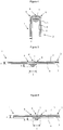
- FIGS. 3 to 8 show the sectional view of the welded zone of the tubular packaging, the section being taken perpendicularly to the axis of the tubular body.
- the figure 3 illustrates a first embodiment of the invention.
- the tubular body 1 is formed by butt welding the ends of a flexible film 2 of thickness e.
- the welded zone 2 is parallel to the axis of the tubular body.
- a reinforcing element of semi-oval section 7 connects the ends of the flexible film 2 and strengthens the welded zone 6.
- the invention is characterized in that the reinforcing element 7 prevents any local deformation of the welded zone 6 perpendicular to the welded ends while hardly changing the flexibility of the package parallel to the welded ends.
- the reinforcing element 7 prevents the variation of the radius of curvature which would have the effect of pulling the welded ends of the flexible film in tension.
- the height h of the reinforcing element depends on the thickness e of the film and must be equal to or greater than the thickness e of the film, that the width l of the element reinforcement must be between 1 mm and 3 mm, and the ratio (le) / h 2 is between 1 and 10.
- the figure 4 illustrates the reinforcing effect of the welded zone 6 by the reinforcing element 7.
- the bending deformation of the welded zone 6 perpendicular to the welded ends becomes impossible because of the geometry of the reinforcing element 7 which locally provides a very high rigidity.
- the flexibility of the package is very little modified because the reinforcing element 7 is biased in the length direction and its section is small in relation to the section of the package which is solicited during a deformation.
- Blind user tests show that the user does not detect the presence of the reinforcing element 7 during the handling of the package to extract the product for example.
- the invention is particularly advantageous when the film is formed of a multilayer structure.
- the figure 3 shows the butt welding of a film with 3 layers; a first layer 3 forming the outer surface of the package, an intermediate layer 4, and a layer 5 forming the inner surface of the package.
- the reinforcing element 7 is welded on the layer 5 and is therefore inside the package.
- the materials constituting the reinforcing element 7 and the lower layer 5 of the multilayer film are generally of the same nature in order to allow the reinforcement element 7 to be welded to the layer 5.
- the materials used for the layer 5 and the element reinforcements 7 are for example polyolefins commonly used to make packaging.
- the intermediate layer 4 is often a barrier layer such as an aluminum layer or an EVOH layer or a metallized PET layer.
- the possible adhesive layers are not shown in the figures of the patent in order not to make the presentation of the invention more cumbersome.
- the layer 3 forming the outer surface of the package is often chosen for its ability to be printed, for its properties to the touch but also for its strength.
- the outer layer 3 is for example a "soft touch" layer based on polyolefin or a layer of PET bi-oriented for its ability to be printed, for its strength, for its transparency, for its brilliance.
- the butt welding of the multilayer film 2 often leads to partial welding because of the nature of the layers and their thin thickness. This results in reduced resistance at the weld.
- the invention avoids any stress on the welded zone having the effect of creating the illustrated defect figure 2 .
- the effect of the reinforcing element 7 on the resistance of the weld is illustrated figure 4 .
- the welded zone 6 is found free of stress and deformation through the action of the reinforcing element 7 whose section is shaped semi-oval.
- the geometry and the small dimension of the reinforcing element 7 has the effect of concentrating the stresses and deformations in the zones 8 and 9 which are remote from the weld. Because of its small size and shape, the section of the reinforcing element 7 is not deformable under the action of finger pressure.
- the section of the reinforcing member 7 locally significantly increases the bending stiffness of the package in the direction perpendicular to the welded ends.
- This increase in the stiffness of the package perpendicular to the welded ends is locally over a distance total less than or equal to 3 mm.
- the order of magnitude of the increase of the bending stiffness at the weld and perpendicular to the welded ends is at least 25 or even 100.
- the reinforcing element 7 has little influence on the weld. stiffness of the package in the direction parallel to the welded ends.
- the reinforcing element 7 only increases the bending stiffness of the package by a factor of less than or equal to 4.
- the various tests carried out show that the user does not detect the presence of the reinforcing element 7 when using the package.
- the reinforcing element 7 is invisible because it is located inside the packaging and imperceptible because the properties of the packaging are modified only very locally.
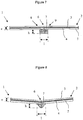
- the Figures 5, 6 , and 7 show other sections of the reinforcing element 7 advantageous.
- the figure 5 illustrates an isosceles trapezium-shaped section reinforcement element
- the figure 6 an isosceles trapezoid shaped reinforcement element whose two sides are concave and the figure 7 a sectional reinforcement element in the form of a rectangle.
- the geometries of the reinforcing element illustrated Figures 5 and 6 allow to limit the concentration of stress that can appear in zones 8 and 9 when the multilayer film is folded strongly at the weld.
- These sections of the reinforcing element 7 allow a more gradual transition of the deformation of the multilayer film in the zones 8 and 9 and avoid possible stress concentrations which would have the effect of degrading the multilayer film.
- the figure 7 illustrates the section of a reinforcing element 7 which is easy to produce but which can create high concentrations of stresses in the zones 8 and 9 during the bending of the film 1 along the weld 6.
- the figure 8 shows a variant of the invention consisting in prestressing the multilayer film by the reinforcing element of section 7 at the level of the weld 6.
- the prestressing has the effect of pressing the ends of the film against each other butt weld level 6.
- the illustrated multilayer film Figures 3 to 8 has a layer 3 forming the upper surface of the laminate; a second layer 5 forming the surface bottom of the laminate and a layer 4 trapped between layers 3 and 5; said layers 3, 4, and 5 may be of different nature; and said layers 3, 4, and 5 being interconnected at their interface.
- the multilayer film 2 generally comprises one or more non-welding layers (s) end to end.
- Layer 3 is usually chosen for its ability to be printed. This layer consists for example of PE or PP, paper, PET or BOPP. This layer may be printed on its outer face forming the surface of the multilayer film or on its inner face being trapped in the thickness of the multilayer film.
- the layer 4 forming a thin layer with barrier properties is generally not welded at its ends.
- the layer 4 is for example an aluminum foil or a layer of EVOH (ethylene vinyl alcohol).
- the layer 5 forming the inner surface of the tube is welded at its ends.
- a polyolefin layer 5 is advantageous.
- the reinforcing element 7 is made integral with the lower layer 5 by welding.
- the reinforcing element 7 comprises at least one layer of the same nature as the lower layer 5 of the multilayer film.
- the reinforcing element 7 it is often advantageous to use the reinforcing element 7 to jointly improve the strength of the weld and its impermeability properties.
- the use of a multilayer reinforcing element and / or containing oxygen absorbers also makes it possible to improve the impermeability of the zone welded to oxygen for example.
- the combination of an aluminum layer in the flexible film with a multilayer reinforcing element or containing oxygen absorbers makes it possible to manufacture packaging of great impermeability.
- a multilayer reinforcing element will advantageously comprise a thin layer of EVOH or other barrier polymer.
- the reinforcing element 7 is advantageously used to jointly improve the resistance of the weld and the protection against forgery of the packaging.
- the reinforcing element 7 can contain additives in the form of nanoparticles such as salts or metal oxides or multilayer micro-additives whose combinations of layers and colors can give more than 37 million unique codes.
- a first method is to extrude a bead of plastic material and deposit it in the molten state on the ends of the flexible film.
- the heat contained in the bead is used to weld the bead to the layer 5 of the flexible film, and butt-weld at least partially the ends of the flexible film.
- the bead is then shaped using a geometry tool adapted to form the reinforcing element whose section corresponds to the dimensions defined in the invention.
- the geometry of the bead is cylindrical; said cylindrical bead is deposited in the molten state on the ends of the flexible film; part of the heat contained in the cylindrical bead is transferred to the flexible film at the ends; said bead is shaped and pressed against the surface of the flexible film to form the reinforcing element 7 whose section corresponds to the description made in the invention; the profile is cooled as well as the welded zone 6.
- Deposition of the melt bead is implemented by relative movement between the extruder and the flexible film.
- the extrusion device is fixed and the package moves at a constant speed with respect to said extrusion device.
- the forming operation of the reinforcing element is carried out by pressing the bead in a form tool.
- the formatting tool is fixed relative to the cord and the flexible film.
- the melt bead is pressed against the form tool comprising a groove whose section corresponds to the section of the reinforcing element.
- the form tool is maintained at a temperature below that of the cord, which has the effect of cooling the reinforcing element jointly or immediately after its formation.
- the shaping tool moves together with the bead in the molten state to avoid friction during the shaping operation of the reinforcing member.
- the form tool may be a wheel comprising a groove on its periphery whose section corresponds to the section of the reinforcing element.
- the tangential speed of the wheel at the interface with the flexible film is equal to the moving speed of the flexible film.
- the wheel is rotated by the displacement of the flexible film.
- a second method of producing the weld is based on extruding a bead whose section is close to the section of the reinforcing element and then forming the final geometry of the reinforcing element according to the first method.
- a third method of producing the weld is based on the use of a previously made reinforcing element 7 and then assembling it on the end-to-end ends of the flexible film 2.
- a preferred embodiment of the third method consists of soldering the reinforcing element 7 to the flexible film 2 together with the butt-welding operation of the ends of the flexible film 2.
- the invention is particularly advantageous because it allows for packaging by welding end-to-end films that combine solder layers and layers that do not weld end to end.
- the invention makes it possible to assemble end to end the ends of a film whose ends are partially welded.
- the invention makes it possible to obtain welded packages with a very high resistance at the welded zone.
- the packages obtained can be printed on their entire surface without breaking the impression in the welded zone.
- the invention makes it possible to obtain packages of high strength and improved aesthetics.
- the invention is particularly advantageous for the production of packaging tubes.
- the invention also has many advantages for producing flexible packaging pouches.
Claims (16)
- Rohrförmiger Verpackungskörper (1), der ausgehend von einer Folie (2) einer Dicke e gebildet, wird, deren Enden stumpf aneinandergeschweißt und von einem Verstärkungselement (7) aus Kunststoff bedeckt sind, das auf der Innenfläche des rohrförmigen Körpers angeordnet ist und einen durch eine Breite l und eine Höhe h definierten Querschnitt hat, wobei der rohrförmige Körper dadurch gekennzeichnet ist, dass alle folgenden Bedingungen erfüllt werden müssen:- h ist gleich oder höher als e,- das Verhältnis (l.e)/h2 liegt zwischen 1 und 10.
- Rohrförmiger Körper nach Anspruch 1, dadurch gekennzeichnet, dass die Höhe h maximal gleich dem Doppelten der Dicke e ist.
- Rohrförmiger Körper nach Anspruch 1 oder 2, dadurch gekennzeichnet, dass die folgenden Bedingungen ebenfalls erfüllt werden müssen:- h liegt zwischen 100 µm und 500 µm,- e liegt zwischen 100 µm und 400 µm.
- Rohrförmiger Körper nach einem der Ansprüche 2 oder 3, dadurch gekennzeichnet, dass die Höhe h gleich dem 1,2-Fachen der Dicke e ist.
- Rohrförmiger Körper nach einem der vorhergehenden Ansprüche, dadurch gekennzeichnet, dass l zwischen 1 mm und 3 mm liegt.
- Rohrförmiger Körper nach einem der vorhergehenden Ansprüche, dadurch gekennzeichnet, dass das Verstärkungselement einen Querschnitt in Form eines Halbovals hat.
- Rohrförmiger Körper nach einem der Ansprüche 1 bis 4, dadurch gekennzeichnet, dass das Verstärkungselement einen Querschnitt in Form eines gleichschenkligen Trapezes hat.
- Rohrförmiger Körper nach einem der Ansprüche 1 bis 4, dadurch gekennzeichnet, dass das Verstärkungselement einen Querschnitt in Form eines gleichschenkligen Trapezes hat, dessen zwei Seiten konkav sind.
- Rohrförmiger Körper nach einem der Ansprüche 1 bis 4, dadurch gekennzeichnet, dass das Verstärkungselement einen Querschnitt in Form eines Rechtecks hat.
- Rohrförmiger Körper nach einem der vorhergehenden Ansprüche, dadurch gekennzeichnet, dass die Enden der Folie abgeschrägt sind.
- Rohrförmiger Körper nach einem der vorhergehenden Ansprüche, dadurch gekennzeichnet, dass die Folie eine Mehrschichtfolie ist und mindestens eine Schicht enthält, deren Stumpfschweißung nur teilweise oder nicht vorhanden ist.
- Rohrförmiger Körper nach Anspruch 11, dadurch gekennzeichnet, dass die Schicht die Außenfläche der Verpackung bildet.
- Rohrförmiger Körper nach einem der vorhergehenden Ansprüche, dadurch gekennzeichnet, dass das Verstärkungselement mehrere Schichten enthält.
- Rohrförmiger Körper nach einem der vorhergehenden Ansprüche, dadurch gekennzeichnet, dass das Verstärkungselement Sauerstoffabsorber enthält.
- Rohrförmiger Körper nach einem der vorhergehenden Ansprüche, dadurch gekennzeichnet, dass das Verstärkungselement pulverförmige mikroskopische oder nanoskopische Tracer enthält, die es ermöglichen, Fälschungen zu bekämpfen.
- Rohrförmiger Körper nach einem der vorhergehenden Ansprüche, dadurch gekennzeichnet, dass das Verhältnis der Biegesteifigkeit im Bereich der Schweißverbindung zwischen der lotrechten Richtung und der parallelen Richtung zur Schweißverbindung mindestens gleich 25 ist.
Priority Applications (2)
| Application Number | Priority Date | Filing Date | Title |
|---|---|---|---|
| EP13744830.4A EP2861505B1 (de) | 2012-06-15 | 2013-06-12 | Rohrförmiger stumpfgeschweisster verpackungskörper |
| PL13744830T PL2861505T3 (pl) | 2012-06-15 | 2013-06-12 | Korpus rurkowy opakowaniowy zgrzewany doczołowo |
Applications Claiming Priority (3)
| Application Number | Priority Date | Filing Date | Title |
|---|---|---|---|
| EP12172306.8A EP2674368A1 (de) | 2012-06-15 | 2012-06-15 | Stoßgeschweißter rohrförmiger Verpackungskörper |
| EP13744830.4A EP2861505B1 (de) | 2012-06-15 | 2013-06-12 | Rohrförmiger stumpfgeschweisster verpackungskörper |
| PCT/IB2013/054816 WO2013186723A2 (fr) | 2012-06-15 | 2013-06-12 | Corps tubulaire d'emballage soude bout a bout |
Publications (2)
| Publication Number | Publication Date |
|---|---|
| EP2861505A2 EP2861505A2 (de) | 2015-04-22 |
| EP2861505B1 true EP2861505B1 (de) | 2017-08-09 |
Family
ID=48914385
Family Applications (2)
| Application Number | Title | Priority Date | Filing Date |
|---|---|---|---|
| EP12172306.8A Withdrawn EP2674368A1 (de) | 2012-06-15 | 2012-06-15 | Stoßgeschweißter rohrförmiger Verpackungskörper |
| EP13744830.4A Active EP2861505B1 (de) | 2012-06-15 | 2013-06-12 | Rohrförmiger stumpfgeschweisster verpackungskörper |
Family Applications Before (1)
| Application Number | Title | Priority Date | Filing Date |
|---|---|---|---|
| EP12172306.8A Withdrawn EP2674368A1 (de) | 2012-06-15 | 2012-06-15 | Stoßgeschweißter rohrförmiger Verpackungskörper |
Country Status (13)
| Country | Link |
|---|---|
| US (1) | US11124342B2 (de) |
| EP (2) | EP2674368A1 (de) |
| JP (1) | JP6216373B2 (de) |
| KR (1) | KR102385724B1 (de) |
| CN (1) | CN104349987B (de) |
| BR (1) | BR112014031187B1 (de) |
| CA (1) | CA2875647C (de) |
| ES (1) | ES2642389T3 (de) |
| HK (1) | HK1202105A1 (de) |
| MX (1) | MX352300B (de) |
| PL (1) | PL2861505T3 (de) |
| RU (1) | RU2642043C2 (de) |
| WO (1) | WO2013186723A2 (de) |
Cited By (1)
| Publication number | Priority date | Publication date | Assignee | Title |
|---|---|---|---|---|
| WO2020098906A1 (de) | 2018-11-12 | 2020-05-22 | Packsys Global Ag | Verfahren zum herstellen von flexiblen tubenkörpern für verpackungstuben, flexibler tubenkörper für verpackungstuben und vorrichtung zur herstellung von flexiblen tubenkörpern für verpackungstuben |
Families Citing this family (3)
| Publication number | Priority date | Publication date | Assignee | Title |
|---|---|---|---|---|
| IT201600104605A1 (it) * | 2016-10-18 | 2018-04-18 | Safta Spa | Involucro e film multistrato |
| JP2020033060A (ja) * | 2018-08-30 | 2020-03-05 | 株式会社吉野工業所 | チューブ容器 |
| EP4082757A1 (de) | 2021-04-26 | 2022-11-02 | Aisapack Holding SA | Verpackung, bei der die verschweissung im aufdruck verborgen ist, und entsprechendes herstellungsverfahren |
Family Cites Families (24)
| Publication number | Priority date | Publication date | Assignee | Title |
|---|---|---|---|---|
| US2430046A (en) * | 1942-11-18 | 1947-11-04 | Dreyfus Camille | Collapsible tube |
| DE1729018A1 (de) * | 1967-12-27 | 1971-06-03 | Spiess C F & Sohn | Verfahren zum Herstellen von Tuben,insbesondere von Tubenkoerpern aus Folien |
| DE3045086A1 (de) | 1980-11-29 | 1982-06-24 | Hoechst Ag, 6000 Frankfurt | Schlauchhuelle, insbesondere wursthuelle, mit wasserdampfundurchlaessiger schicht, verfahren zu ihrer herstellung und ihre verwendung |
| DE3139481A1 (de) | 1981-10-03 | 1983-05-05 | Hoechst Ag, 6230 Frankfurt | Fuer zu raeuchernde lebensmittel, insbesondere fuer zu raeuchernde wurstwaren geeignete schlauchhuelle, verfahren zu ihrer herstellung und ihre verwendung |
| SE445031B (sv) * | 1984-10-02 | 1986-05-26 | Akerlund & Rausing Ab | Forpackningstub samt forfarande och anordning for tillverkning derav |
| US5197935A (en) | 1989-11-13 | 1993-03-30 | Tetra Alpha Holdings S.A. | Package for flowable contents with an externally smoothly constructed sealing seam, a method of producing such a package and an apparatus for carrying out the method |
| DE69231344T2 (de) * | 1991-12-26 | 2001-03-29 | Toyo Boseki | Gassperrfilm |
| JP3484542B2 (ja) | 1992-11-30 | 2004-01-06 | 大日本印刷株式会社 | チューブ容器胴部 |
| JP3441860B2 (ja) * | 1994-11-08 | 2003-09-02 | キヤノン株式会社 | 管状フィルムの製造方法及び製造装置 |
| JPH08324600A (ja) * | 1995-03-27 | 1996-12-10 | Dainippon Printing Co Ltd | ラミネートチューブ |
| JPH10120990A (ja) | 1996-10-14 | 1998-05-12 | Oji Paper Co Ltd | 粘着シート |
| US7038766B2 (en) | 1999-04-01 | 2006-05-02 | Microtrace, Llc | Identification particles and system and method for retrospective identification using spectral codes |
| JP2001206458A (ja) * | 2000-01-26 | 2001-07-31 | Toyo Seikan Kaisha Ltd | 加熱調理用包装体 |
| JP2002145242A (ja) * | 2000-11-06 | 2002-05-22 | Nippo Corp | 紙容器および紙容器の蓋ならびにそれらの製造方法 |
| CN1565833A (zh) * | 2003-06-16 | 2005-01-19 | 林津强 | 一种塑料复合管连接方法 |
| JP4508850B2 (ja) * | 2004-12-01 | 2010-07-21 | 株式会社デンソー | 自動変速機の制御装置 |
| WO2006135315A1 (en) * | 2005-06-17 | 2006-12-21 | Tetra Laval Holdings & Finance S.A. | A packaging laminate and packaging container produced therefrom |
| EP2004389B1 (de) | 2006-04-06 | 2011-01-26 | Aisapack Holding SA | Schlauchförmiger verpackungskörper aus thermoplastmaterial mit eingebettetem streifen |
| RU2449932C2 (ru) | 2006-04-06 | 2012-05-10 | Айзапак Холдинг С.А. | Гибкая многослойная структура для тюбиков |
| EP1905570A1 (de) * | 2006-09-28 | 2008-04-02 | Aisapack Holding SA | Verfahren und Vorrichtung zum internen Schweissen von Kunststoffrohren |
| FR2921860B1 (fr) * | 2007-10-08 | 2011-04-29 | Carbone Lorraine Composants | Procede de fabrication d'un dispositif isolant tubulaire et dispositif correspondant |
| JP4490493B2 (ja) | 2008-07-11 | 2010-06-23 | 株式会社悠心 | 逆止機能ノズルを備えるフレキシブル包装袋 |
| FR2944780B1 (fr) * | 2009-04-28 | 2011-06-10 | Lablabo | Dispositif de conditionnement et de distribution du type flacon-poche. |
| EP2511089A1 (de) | 2011-04-15 | 2012-10-17 | Aisapack Holding SA | Mehrschichtige Verpackungsstruktur |
-
2012
- 2012-06-15 EP EP12172306.8A patent/EP2674368A1/de not_active Withdrawn
-
2013
- 2013-06-12 PL PL13744830T patent/PL2861505T3/pl unknown
- 2013-06-12 RU RU2014152788A patent/RU2642043C2/ru active
- 2013-06-12 CA CA2875647A patent/CA2875647C/fr active Active
- 2013-06-12 WO PCT/IB2013/054816 patent/WO2013186723A2/fr active Application Filing
- 2013-06-12 ES ES13744830.4T patent/ES2642389T3/es active Active
- 2013-06-12 CN CN201380031049.7A patent/CN104349987B/zh active Active
- 2013-06-12 KR KR1020157000895A patent/KR102385724B1/ko active IP Right Grant
- 2013-06-12 BR BR112014031187-0A patent/BR112014031187B1/pt active IP Right Grant
- 2013-06-12 MX MX2014015245A patent/MX352300B/es active IP Right Grant
- 2013-06-12 JP JP2015516731A patent/JP6216373B2/ja active Active
- 2013-06-12 US US14/407,075 patent/US11124342B2/en active Active
- 2013-06-12 EP EP13744830.4A patent/EP2861505B1/de active Active
-
2015
- 2015-03-11 HK HK15102510.0A patent/HK1202105A1/xx unknown
Cited By (1)
| Publication number | Priority date | Publication date | Assignee | Title |
|---|---|---|---|---|
| WO2020098906A1 (de) | 2018-11-12 | 2020-05-22 | Packsys Global Ag | Verfahren zum herstellen von flexiblen tubenkörpern für verpackungstuben, flexibler tubenkörper für verpackungstuben und vorrichtung zur herstellung von flexiblen tubenkörpern für verpackungstuben |
Also Published As
| Publication number | Publication date |
|---|---|
| JP6216373B2 (ja) | 2017-10-18 |
| KR102385724B1 (ko) | 2022-04-13 |
| EP2861505A2 (de) | 2015-04-22 |
| US20150132517A1 (en) | 2015-05-14 |
| JP2015527258A (ja) | 2015-09-17 |
| MX352300B (es) | 2017-11-17 |
| MX2014015245A (es) | 2015-03-05 |
| BR112014031187A2 (pt) | 2017-06-27 |
| KR20150024891A (ko) | 2015-03-09 |
| BR112014031187B1 (pt) | 2021-01-19 |
| CA2875647A1 (fr) | 2013-12-19 |
| CA2875647C (fr) | 2020-01-14 |
| CN104349987A (zh) | 2015-02-11 |
| EP2674368A1 (de) | 2013-12-18 |
| RU2642043C2 (ru) | 2018-01-23 |
| ES2642389T3 (es) | 2017-11-16 |
| US11124342B2 (en) | 2021-09-21 |
| RU2014152788A (ru) | 2016-08-10 |
| PL2861505T3 (pl) | 2018-01-31 |
| CN104349987B (zh) | 2018-09-21 |
| HK1202105A1 (en) | 2015-09-18 |
| WO2013186723A3 (fr) | 2014-02-27 |
| WO2013186723A2 (fr) | 2013-12-19 |
Similar Documents
| Publication | Publication Date | Title |
|---|---|---|
| CA2646728C (fr) | Structure multicouche flexible pour tubes | |
| EP2004389B1 (de) | Schlauchförmiger verpackungskörper aus thermoplastmaterial mit eingebettetem streifen | |
| EP2007567B1 (de) | Verpackung aus endversiegeltem film | |
| EP2861505B1 (de) | Rohrförmiger stumpfgeschweisster verpackungskörper | |
| CA2814343C (fr) | Emballage flexible fabrique par soudage et contenant une matiere recyclee ou issue de ressources renouvelables | |
| EP1720692B1 (de) | Mehrlagige struktur mit konkaver fläche, verfahren zur herstellung der struktur und vorrichtung zur herstellung der struktur | |
| EP3131738A1 (de) | Verfahren und vorrichtung zur extrusion und etikettierung einer verpackungstube | |
| EP3619035B1 (de) | Mehrschichtige kunststoffrohrstruktur | |
| EP1884348A1 (de) | Kombiniertes Schweiss- und Klebeverfahren zur Herstellung von Verpackungen und danach hergestellte Verpackung | |
| WO2007105135A1 (fr) | Objet synthetique multicouche | |
| EP1974894A1 (de) | Abrisszone für Plastikfolie | |
| EP1884349A1 (de) | Behälter aus stoßgeschweisster mehrlagiger Folie | |
| WO2007113783A1 (fr) | Emballage forme d' un film a plusieurs couches soude bout a bout | |
| FR2557502A1 (fr) | Substrat stratifie contenant un polymere fluore et recipient distributeur repliable realise a partir d'un tel substrat | |
| EP1862392A1 (de) | Flexible Kunststoffverpackung | |
| FR2828435A1 (fr) | Film multicouche thermoretractable |
Legal Events
| Date | Code | Title | Description |
|---|---|---|---|
| PUAI | Public reference made under article 153(3) epc to a published international application that has entered the european phase |
Free format text: ORIGINAL CODE: 0009012 |
|
| 17P | Request for examination filed |
Effective date: 20150113 |
|
| AK | Designated contracting states |
Kind code of ref document: A2 Designated state(s): AL AT BE BG CH CY CZ DE DK EE ES FI FR GB GR HR HU IE IS IT LI LT LU LV MC MK MT NL NO PL PT RO RS SE SI SK SM TR |
|
| AX | Request for extension of the european patent |
Extension state: BA ME |
|
| DAX | Request for extension of the european patent (deleted) | ||
| 17Q | First examination report despatched |
Effective date: 20160226 |
|
| TPAC | Observations filed by third parties |
Free format text: ORIGINAL CODE: EPIDOSNTIPA |
|
| GRAP | Despatch of communication of intention to grant a patent |
Free format text: ORIGINAL CODE: EPIDOSNIGR1 |
|
| STAA | Information on the status of an ep patent application or granted ep patent |
Free format text: STATUS: GRANT OF PATENT IS INTENDED |
|
| INTG | Intention to grant announced |
Effective date: 20170105 |
|
| GRAS | Grant fee paid |
Free format text: ORIGINAL CODE: EPIDOSNIGR3 |
|
| GRAA | (expected) grant |
Free format text: ORIGINAL CODE: 0009210 |
|
| STAA | Information on the status of an ep patent application or granted ep patent |
Free format text: STATUS: THE PATENT HAS BEEN GRANTED |
|
| AK | Designated contracting states |
Kind code of ref document: B1 Designated state(s): AL AT BE BG CH CY CZ DE DK EE ES FI FR GB GR HR HU IE IS IT LI LT LU LV MC MK MT NL NO PL PT RO RS SE SI SK SM TR |
|
| REG | Reference to a national code |
Ref country code: GB Ref legal event code: FG4D Free format text: NOT ENGLISH |
|
| REG | Reference to a national code |
Ref country code: CH Ref legal event code: EP Ref country code: AT Ref legal event code: REF Ref document number: 916530 Country of ref document: AT Kind code of ref document: T Effective date: 20170815 |
|
| REG | Reference to a national code |
Ref country code: IE Ref legal event code: FG4D Free format text: LANGUAGE OF EP DOCUMENT: FRENCH |
|
| REG | Reference to a national code |
Ref country code: CH Ref legal event code: NV Representative=s name: ANDRE ROLAND S.A., CH |
|
| REG | Reference to a national code |
Ref country code: DE Ref legal event code: R096 Ref document number: 602013024794 Country of ref document: DE |
|
| REG | Reference to a national code |
Ref country code: SE Ref legal event code: TRGR |
|
| REG | Reference to a national code |
Ref country code: ES Ref legal event code: FG2A Ref document number: 2642389 Country of ref document: ES Kind code of ref document: T3 Effective date: 20171116 |
|
| REG | Reference to a national code |
Ref country code: NL Ref legal event code: MP Effective date: 20170809 |
|
| REG | Reference to a national code |
Ref country code: LT Ref legal event code: MG4D |
|
| PG25 | Lapsed in a contracting state [announced via postgrant information from national office to epo] |
Ref country code: HR Free format text: LAPSE BECAUSE OF FAILURE TO SUBMIT A TRANSLATION OF THE DESCRIPTION OR TO PAY THE FEE WITHIN THE PRESCRIBED TIME-LIMIT Effective date: 20170809 Ref country code: NL Free format text: LAPSE BECAUSE OF FAILURE TO SUBMIT A TRANSLATION OF THE DESCRIPTION OR TO PAY THE FEE WITHIN THE PRESCRIBED TIME-LIMIT Effective date: 20170809 Ref country code: NO Free format text: LAPSE BECAUSE OF FAILURE TO SUBMIT A TRANSLATION OF THE DESCRIPTION OR TO PAY THE FEE WITHIN THE PRESCRIBED TIME-LIMIT Effective date: 20171109 Ref country code: LT Free format text: LAPSE BECAUSE OF FAILURE TO SUBMIT A TRANSLATION OF THE DESCRIPTION OR TO PAY THE FEE WITHIN THE PRESCRIBED TIME-LIMIT Effective date: 20170809 Ref country code: FI Free format text: LAPSE BECAUSE OF FAILURE TO SUBMIT A TRANSLATION OF THE DESCRIPTION OR TO PAY THE FEE WITHIN THE PRESCRIBED TIME-LIMIT Effective date: 20170809 |
|
| REG | Reference to a national code |
Ref country code: SK Ref legal event code: T3 Ref document number: E 25404 Country of ref document: SK |
|
| PG25 | Lapsed in a contracting state [announced via postgrant information from national office to epo] |
Ref country code: GR Free format text: LAPSE BECAUSE OF FAILURE TO SUBMIT A TRANSLATION OF THE DESCRIPTION OR TO PAY THE FEE WITHIN THE PRESCRIBED TIME-LIMIT Effective date: 20171110 Ref country code: IS Free format text: LAPSE BECAUSE OF FAILURE TO SUBMIT A TRANSLATION OF THE DESCRIPTION OR TO PAY THE FEE WITHIN THE PRESCRIBED TIME-LIMIT Effective date: 20171209 Ref country code: LV Free format text: LAPSE BECAUSE OF FAILURE TO SUBMIT A TRANSLATION OF THE DESCRIPTION OR TO PAY THE FEE WITHIN THE PRESCRIBED TIME-LIMIT Effective date: 20170809 Ref country code: RS Free format text: LAPSE BECAUSE OF FAILURE TO SUBMIT A TRANSLATION OF THE DESCRIPTION OR TO PAY THE FEE WITHIN THE PRESCRIBED TIME-LIMIT Effective date: 20170809 |
|
| PG25 | Lapsed in a contracting state [announced via postgrant information from national office to epo] |
Ref country code: CZ Free format text: LAPSE BECAUSE OF FAILURE TO SUBMIT A TRANSLATION OF THE DESCRIPTION OR TO PAY THE FEE WITHIN THE PRESCRIBED TIME-LIMIT Effective date: 20170809 Ref country code: DK Free format text: LAPSE BECAUSE OF FAILURE TO SUBMIT A TRANSLATION OF THE DESCRIPTION OR TO PAY THE FEE WITHIN THE PRESCRIBED TIME-LIMIT Effective date: 20170809 Ref country code: RO Free format text: LAPSE BECAUSE OF FAILURE TO SUBMIT A TRANSLATION OF THE DESCRIPTION OR TO PAY THE FEE WITHIN THE PRESCRIBED TIME-LIMIT Effective date: 20170809 |
|
| REG | Reference to a national code |
Ref country code: DE Ref legal event code: R097 Ref document number: 602013024794 Country of ref document: DE |
|
| PG25 | Lapsed in a contracting state [announced via postgrant information from national office to epo] |
Ref country code: EE Free format text: LAPSE BECAUSE OF FAILURE TO SUBMIT A TRANSLATION OF THE DESCRIPTION OR TO PAY THE FEE WITHIN THE PRESCRIBED TIME-LIMIT Effective date: 20170809 Ref country code: SM Free format text: LAPSE BECAUSE OF FAILURE TO SUBMIT A TRANSLATION OF THE DESCRIPTION OR TO PAY THE FEE WITHIN THE PRESCRIBED TIME-LIMIT Effective date: 20170809 |
|
| PLBE | No opposition filed within time limit |
Free format text: ORIGINAL CODE: 0009261 |
|
| STAA | Information on the status of an ep patent application or granted ep patent |
Free format text: STATUS: NO OPPOSITION FILED WITHIN TIME LIMIT |
|
| REG | Reference to a national code |
Ref country code: FR Ref legal event code: PLFP Year of fee payment: 6 |
|
| 26N | No opposition filed |
Effective date: 20180511 |
|
| PG25 | Lapsed in a contracting state [announced via postgrant information from national office to epo] |
Ref country code: SI Free format text: LAPSE BECAUSE OF FAILURE TO SUBMIT A TRANSLATION OF THE DESCRIPTION OR TO PAY THE FEE WITHIN THE PRESCRIBED TIME-LIMIT Effective date: 20170809 |
|
| PG25 | Lapsed in a contracting state [announced via postgrant information from national office to epo] |
Ref country code: MT Free format text: LAPSE BECAUSE OF FAILURE TO SUBMIT A TRANSLATION OF THE DESCRIPTION OR TO PAY THE FEE WITHIN THE PRESCRIBED TIME-LIMIT Effective date: 20170809 |
|
| REG | Reference to a national code |
Ref country code: BE Ref legal event code: MM Effective date: 20180630 |
|
| REG | Reference to a national code |
Ref country code: IE Ref legal event code: MM4A |
|
| PG25 | Lapsed in a contracting state [announced via postgrant information from national office to epo] |
Ref country code: LU Free format text: LAPSE BECAUSE OF NON-PAYMENT OF DUE FEES Effective date: 20180612 Ref country code: MC Free format text: LAPSE BECAUSE OF FAILURE TO SUBMIT A TRANSLATION OF THE DESCRIPTION OR TO PAY THE FEE WITHIN THE PRESCRIBED TIME-LIMIT Effective date: 20170809 |
|
| PG25 | Lapsed in a contracting state [announced via postgrant information from national office to epo] |
Ref country code: IE Free format text: LAPSE BECAUSE OF NON-PAYMENT OF DUE FEES Effective date: 20180612 |
|
| PG25 | Lapsed in a contracting state [announced via postgrant information from national office to epo] |
Ref country code: BE Free format text: LAPSE BECAUSE OF NON-PAYMENT OF DUE FEES Effective date: 20180630 |
|
| PG25 | Lapsed in a contracting state [announced via postgrant information from national office to epo] |
Ref country code: PT Free format text: LAPSE BECAUSE OF FAILURE TO SUBMIT A TRANSLATION OF THE DESCRIPTION OR TO PAY THE FEE WITHIN THE PRESCRIBED TIME-LIMIT Effective date: 20170809 |
|
| PG25 | Lapsed in a contracting state [announced via postgrant information from national office to epo] |
Ref country code: MK Free format text: LAPSE BECAUSE OF NON-PAYMENT OF DUE FEES Effective date: 20170809 Ref country code: CY Free format text: LAPSE BECAUSE OF FAILURE TO SUBMIT A TRANSLATION OF THE DESCRIPTION OR TO PAY THE FEE WITHIN THE PRESCRIBED TIME-LIMIT Effective date: 20170809 Ref country code: HU Free format text: LAPSE BECAUSE OF FAILURE TO SUBMIT A TRANSLATION OF THE DESCRIPTION OR TO PAY THE FEE WITHIN THE PRESCRIBED TIME-LIMIT; INVALID AB INITIO Effective date: 20130612 |
|
| PG25 | Lapsed in a contracting state [announced via postgrant information from national office to epo] |
Ref country code: AL Free format text: LAPSE BECAUSE OF FAILURE TO SUBMIT A TRANSLATION OF THE DESCRIPTION OR TO PAY THE FEE WITHIN THE PRESCRIBED TIME-LIMIT Effective date: 20170809 |
|
| REG | Reference to a national code |
Ref country code: AT Ref legal event code: UEP Ref document number: 916530 Country of ref document: AT Kind code of ref document: T Effective date: 20170809 |
|
| P01 | Opt-out of the competence of the unified patent court (upc) registered |
Effective date: 20230518 |
|
| PGFP | Annual fee paid to national office [announced via postgrant information from national office to epo] |
Ref country code: DE Payment date: 20230620 Year of fee payment: 11 Ref country code: BG Payment date: 20230627 Year of fee payment: 11 Ref country code: FR Payment date: 20230628 Year of fee payment: 11 |
|
| PGFP | Annual fee paid to national office [announced via postgrant information from national office to epo] |
Ref country code: TR Payment date: 20230609 Year of fee payment: 11 Ref country code: SK Payment date: 20230606 Year of fee payment: 11 Ref country code: SE Payment date: 20230620 Year of fee payment: 11 Ref country code: PL Payment date: 20230601 Year of fee payment: 11 Ref country code: AT Payment date: 20230621 Year of fee payment: 11 |
|
| PGFP | Annual fee paid to national office [announced via postgrant information from national office to epo] |
Ref country code: IT Payment date: 20230623 Year of fee payment: 11 Ref country code: GB Payment date: 20230622 Year of fee payment: 11 Ref country code: ES Payment date: 20230829 Year of fee payment: 11 Ref country code: CH Payment date: 20230702 Year of fee payment: 11 |