EP2857621A1 - Scharnier für ein Möbelteil und Möbel - Google Patents
Scharnier für ein Möbelteil und Möbel Download PDFInfo
- Publication number
- EP2857621A1 EP2857621A1 EP14187250.7A EP14187250A EP2857621A1 EP 2857621 A1 EP2857621 A1 EP 2857621A1 EP 14187250 A EP14187250 A EP 14187250A EP 2857621 A1 EP2857621 A1 EP 2857621A1
- Authority
- EP
- European Patent Office
- Prior art keywords
- hinge
- lever
- guide
- further lever
- furniture
- Prior art date
- Legal status (The legal status is an assumption and is not a legal conclusion. Google has not performed a legal analysis and makes no representation as to the accuracy of the status listed.)
- Granted
Links
Images



Classifications
-
- E—FIXED CONSTRUCTIONS
- E05—LOCKS; KEYS; WINDOW OR DOOR FITTINGS; SAFES
- E05D—HINGES OR SUSPENSION DEVICES FOR DOORS, WINDOWS OR WINGS
- E05D3/00—Hinges with pins
- E05D3/06—Hinges with pins with two or more pins
- E05D3/12—Hinges with pins with two or more pins with two parallel pins and one arm
-
- E—FIXED CONSTRUCTIONS
- E05—LOCKS; KEYS; WINDOW OR DOOR FITTINGS; SAFES
- E05F—DEVICES FOR MOVING WINGS INTO OPEN OR CLOSED POSITION; CHECKS FOR WINGS; WING FITTINGS NOT OTHERWISE PROVIDED FOR, CONCERNED WITH THE FUNCTIONING OF THE WING
- E05F5/00—Braking devices, e.g. checks; Stops; Buffers
- E05F5/006—Braking devices, e.g. checks; Stops; Buffers for hinges having a cup-shaped fixing part, e.g. for attachment to cabinets or furniture
-
- E—FIXED CONSTRUCTIONS
- E05—LOCKS; KEYS; WINDOW OR DOOR FITTINGS; SAFES
- E05D—HINGES OR SUSPENSION DEVICES FOR DOORS, WINDOWS OR WINGS
- E05D11/00—Additional features or accessories of hinges
- E05D11/10—Devices for preventing movement between relatively-movable hinge parts
-
- E—FIXED CONSTRUCTIONS
- E05—LOCKS; KEYS; WINDOW OR DOOR FITTINGS; SAFES
- E05D—HINGES OR SUSPENSION DEVICES FOR DOORS, WINDOWS OR WINGS
- E05D3/00—Hinges with pins
- E05D3/06—Hinges with pins with two or more pins
- E05D3/16—Hinges with pins with two or more pins with seven parallel pins and four arms
-
- E—FIXED CONSTRUCTIONS
- E05—LOCKS; KEYS; WINDOW OR DOOR FITTINGS; SAFES
- E05Y—INDEXING SCHEME ASSOCIATED WITH SUBCLASSES E05D AND E05F, RELATING TO CONSTRUCTION ELEMENTS, ELECTRIC CONTROL, POWER SUPPLY, POWER SIGNAL OR TRANSMISSION, USER INTERFACES, MOUNTING OR COUPLING, DETAILS, ACCESSORIES, AUXILIARY OPERATIONS NOT OTHERWISE PROVIDED FOR, APPLICATION THEREOF
- E05Y2201/00—Constructional elements; Accessories therefor
- E05Y2201/20—Brakes; Disengaging means; Holders; Stops; Valves; Accessories therefor
- E05Y2201/21—Brakes
-
- E—FIXED CONSTRUCTIONS
- E05—LOCKS; KEYS; WINDOW OR DOOR FITTINGS; SAFES
- E05Y—INDEXING SCHEME ASSOCIATED WITH SUBCLASSES E05D AND E05F, RELATING TO CONSTRUCTION ELEMENTS, ELECTRIC CONTROL, POWER SUPPLY, POWER SIGNAL OR TRANSMISSION, USER INTERFACES, MOUNTING OR COUPLING, DETAILS, ACCESSORIES, AUXILIARY OPERATIONS NOT OTHERWISE PROVIDED FOR, APPLICATION THEREOF
- E05Y2201/00—Constructional elements; Accessories therefor
- E05Y2201/20—Brakes; Disengaging means; Holders; Stops; Valves; Accessories therefor
- E05Y2201/214—Disengaging means
-
- E—FIXED CONSTRUCTIONS
- E05—LOCKS; KEYS; WINDOW OR DOOR FITTINGS; SAFES
- E05Y—INDEXING SCHEME ASSOCIATED WITH SUBCLASSES E05D AND E05F, RELATING TO CONSTRUCTION ELEMENTS, ELECTRIC CONTROL, POWER SUPPLY, POWER SIGNAL OR TRANSMISSION, USER INTERFACES, MOUNTING OR COUPLING, DETAILS, ACCESSORIES, AUXILIARY OPERATIONS NOT OTHERWISE PROVIDED FOR, APPLICATION THEREOF
- E05Y2201/00—Constructional elements; Accessories therefor
- E05Y2201/20—Brakes; Disengaging means; Holders; Stops; Valves; Accessories therefor
- E05Y2201/262—Type of motion, e.g. braking
- E05Y2201/264—Type of motion, e.g. braking linear
-
- E—FIXED CONSTRUCTIONS
- E05—LOCKS; KEYS; WINDOW OR DOOR FITTINGS; SAFES
- E05Y—INDEXING SCHEME ASSOCIATED WITH SUBCLASSES E05D AND E05F, RELATING TO CONSTRUCTION ELEMENTS, ELECTRIC CONTROL, POWER SUPPLY, POWER SIGNAL OR TRANSMISSION, USER INTERFACES, MOUNTING OR COUPLING, DETAILS, ACCESSORIES, AUXILIARY OPERATIONS NOT OTHERWISE PROVIDED FOR, APPLICATION THEREOF
- E05Y2900/00—Application of doors, windows, wings or fittings thereof
- E05Y2900/20—Application of doors, windows, wings or fittings thereof for furniture, e.g. cabinets
Definitions
- hinges for the pivotable storage of furniture parts on a carcass. These can comprise an attachable to the body stop or hinge part and a fixable on the movable furniture part hinge part. With the mutually pivotable stop parts furniture parts such as a door or a flap can be moved via a hinged mechanism provided with the hinge.
- double link or four-joint hinges for example, two articulated levers or articulated arms are provided on the hinge.
- Object of the present invention is to make the above-mentioned arrangements with extended functionality compact, in particular occurring malpositions of hinge parts are to be fixed automatically in the hinge mode.
- the invention relates to a hinge for a movable furniture part, which is receivable on the hinge on a body of a piece of furniture, in particular furniture hinge for a door or flap, wherein the hinge has a attachable to the body first stop member, which via a hinge mechanism with a attachable to the movable furniture part second stop member is pivotally connected, wherein the hinge mechanism mounted on hinge axes articulated lever comprises, and wherein a force acting on a damper assembly of the hinge further lever is present, which is pivotally received via a separate axis to the hinge axis and at a proper pivoting movement of the hinge is engaged at times with a guide portion on the hinge, wherein during normal operation of the hinge, the further lever assumes a predetermined standby position before a coupling operation, from which einkup the further lever on the guide portion pelt.
- a matched to the other lever control section is designed such that the other lever on the hinge from a pivotal position, which differs from the predetermined ready position before the engagement, in the intended pivotal movement of the hinge with the Actuator cooperates, so that the actuating portion forcibly displaced the further lever in the engaged state.
- the other lever is thus functionally correct on the hinge in the engaged position on the guide portion of the hinge can be brought in non-control positions of the other lever on the control section.
- the invention is advantageous in terms of the function of the damper assembly.
- the further pivotally mounted lever is temporarily engaged in a complete intended pivotal movement of the hinge with a guide portion on the hinge, wherein the further lever acts on the damper assembly of the hinge.
- the damper assembly of the hinge is used in particular to achieve a damped or braked movement in an end position of the pivoting operation carried out with the hinge in a proper pivoting movement of the hinge. This can be avoided in the furniture-mounted state of the hinge in particular an undesirable strong slamming of the movable furniture part, in particular an unpleasant surcharge noise or damage to the furniture part and the body.
- the actuation of the damper assembly in the interaction of the other lever with the guide portion is advantageously always on the same point of the pivoting movement of the furniture part or at an always identical pivot position of the hinge on the way to an end position of the pivoting movement possible with the hinge.
- the interaction of the other lever with the guide portion can be realized very compact or compact.
- the further lever and the guide section can be provided in areas which are freely available anyway with known corresponding hinges. These areas are preferably in the interior of the hinge, not or hardly visible from the outside. In this way, in the case of an arrangement according to the invention, a desired appearance or a preferred exterior design can be realized without difficulty.
- the hinge may alternatively comprise instead of the damper assembly or in addition to this an actuator, so that further lever is temporarily engaged in a complete intended pivotal movement of the hinge with a guide portion on the hinge, wherein the further lever acts on the actuator of the hinge.
- An actuator is generally understood to mean an element that converts an input to a different output to produce a desired action or effect.
- Aktor850ien example inductively operating electric motors, hydraulic or pneumatic actuators, cylinders, electrochemical or electro-mechanical actuators, piezo actuators are conceivable.
- an electric motor can be operated or controlled via the interaction of the further lever with the guide section.
- a closing and / or opening movement of the movable furniture part can be influenced.
- actuator for example, a locking or latching of the movable furniture part, in particular in a closed end position via the actuator.
- the meshing or engagement can be done for example by means of a catching or threading mechanism.
- the guide section for example, have a slotted guide for the other lever. A portion of the other lever is this exactly matched in shape to the slide guide.
- the system may also be considered as a kind of forced control of the further lever through the guide section.
- the further lever remains unmoved in the non-engaged state and is pivoted in the coupling state.
- the further lever is pivotally received via a separate axis to the hinge axes.
- the further lever may be present, for example, on a stop member in the region between two existing hinge axes.
- an abutment portion of the further lever is present, which is engageable with the guide portion, wherein the adjusting portion comprises a matched to the abutment portion guide edge, which is oriented obliquely in a direction of movement of the abutment portion.
- the adjusting section is provided on a component or lever on which the guide section is formed.
- an extension of the adjusting section is adapted to at least one substantial extension of the guide section.
- the adjusting portion and the guide portion cooperate advantageous.
- the adjusting portion comprises a passage for the abutment portion, wherein the passage has opposite inclined surfaces.
- the adjusting section preferably has oblique surfaces tapering in the direction of passage toward the guide section. This also increases the functionality of the adjusting section.
- the further lever and the guide section are matched to one another in such a way, a coupling state between the other lever and the Guide section that adjusts to a final pivoting movement of the hinge in an end position, in a pivotal movement of the hinge from the end position, picking up.
- the engagement of the further lever on the guide portion and the maintenance of the EinkupplungsSprs takes place over a part or a phase of the entire pivoting movement possible with the hinge.
- this phase describes a phase before reaching an end point of the pivoting movement, that is to say the point of engagement, up to the associated end point, without reversing the direction of movement.
- a decoupled or uncoupled situation of the further lever and the guide section is again achieved during a return movement of the hinge, for example when the movable furniture part is opened relative to the carcass.
- the damper assembly and the actuator is brought back into an initial state according to the action of the lever.
- the damper arrangement or the actuator of the hinge is then operated again.
- the further lever is adapted to act on a portion of a component which is present on the attachable to the body first stop member.
- the damper or an actuator can be accommodated on the attached to the body abutment part, which is advantageous for structural reasons or for reasons of space usually.
- damper arrangement or the actuator is present on the stop member, which is accommodated on the body.
- the guide section is received between two hinge axes of the hinge.
- the guide section may in particular advantageously be present between a positionally fixed joint axis on a stop part and a joint axis which is moved along during the pivoting process.
- the guide section can be accommodated in a particularly space-saving.
- the guide portion comprises a raised or recessed to adjacent areas guide track, which is designed to be tuned for the temporary engagement with an engagement portion of the other lever.
- the guideway is configured as a guide groove or as a guide channel.
- a protruding or raised part such. B. engage an engagement nose on the other lever in the guide groove and possibly moved in Einkupplungsschreib along the guide groove.
- the guide portion has an engagement portion which engages in the coupling state in a guide groove on the other lever.
- the guide section is present in such a way that the guide section is moved along in the case of an intended pivoting movement of the hinge.
- the guide section always moves when the pivoting movement takes place.
- the guide portion may be provided for example on a toggle lever, for example in one piece with this or as an additional part.
- the further lever is pivotally mounted on one of the stop members.
- the further lever is designed as a two-armed lever.
- the other lever can interact with one end with the guide portion and with the other end with the damper assembly and the actuator.
- the further lever can be viewed in the longitudinal direction, in particular in the region of its axis have a bend or bend.
- the further lever and the damper assembly are arranged on the same stop member.
- the action on the damper can be done by the lever in close proximity.
- the further lever and the actuator can be arranged on the same stop member.
- the hinge is designed as a universal joint hinge.
- the universal joint hinge can be particularly stable and designed for different maximum bridgeable angular ranges of the pivoting movement.
- the joint mechanism of a universal joint hinge may in particular comprise a first and a second cross lever and a first and a second connecting lever, wherein the first connecting lever via a first joint on the first stop member and a second joint to the first cross lever is connected via a third stop-side cross-link is received on the second stop member and the second connecting lever is connected via a fourth joint on the second stop member and a fifth joint with the second cross lever, which is received via a sixth stop-side cross lever joint on the first stop member and wherein the two cross levers articulated to each other via a universal joint are. All levers can be pivoted at the same time by an associated one of the aforementioned joints in a joint movement.
- the guide portion is provided between the universal joint and a stop-side cross lever joint and is mitbewegbar according to the movement of one of the two cross levers in an executable with the hinge pivoting movement.
- the hinge is designed as a wide-angle hinge.
- a wide-angle hinge allows in the use state particularly wide opening or pivoting of the movable furniture part relative to a closed position on the body. In particular, larger swing angles up to more than 160 degrees can be realized.
- the invention also relates to a piece of furniture with a movable furniture part, which is posted on a body of the piece of furniture, in particular with a door or flap, wherein the piece of furniture has a hinge according to one of the abovementioned embodiments. This makes it possible to realize the advantages already explained above on the furniture.
- the hinge 1 is designed as a so-called wide-angle or universal joint hinge.
- the hinge 1 comprises a carcass hinge part 2 which can be attached to a carcass K of a furniture part, and a door hinge part or a hinge cup or a movable furniture part hinge part 3, which on a movably received on the hinge 1 on the body furniture part M, such as a door or a flap, attachable.
- the body K and the furniture part M are in FIG. 3a purely schematized partially indicated.
- the hinge parts 2 and 3 can in each case be fastened on the inside of the body or on the movable furniture part, in particular via screws or via quick-fastening means, in particular without tools.
- the two hinge parts 2 and 3 are connected to each other by four hinge arms 4 to 7 via a hinge mechanism to each other pivotally.
- the articulated arms comprise a first cross arm 4 and a second cross arm 5 and a first connecting arm 6 and a second connecting arm 7.
- the hinge mechanism seven pivot joints 8 to 14, which are hereinafter referred to as the first to sixth joint and as a universal joint.
- the first joint 8 is used for pivotally receiving the first connecting arm 6 on the body hinge part 2, wherein the connecting arm 6 is connected via a second joint 9 with the first cross arm 4, which in turn is pivotally received on the furniture part hinge part 3 via a third joint 10.
- the furniture part hinge part 3 is also articulated about a fourth joint 11 of the second connecting arm 7 and pivotally connected via a fifth joint 12 with the second cross arm 5.
- the second cross arm 5 is also accommodated on the carcass hinge part 2 via a sixth joint 13 articulated on the carcass hinge part 2.
- the two cross arms 4, 5 are hinged together via a universal joint 14. All joint axes of the joints 8 to 14 are parallel or perpendicular to the cutting plane of the FIGS. 3a, 4a ,
- the hinge 1 hinge mechanism can in the mounted state on the furniture thus the movable furniture part M from its closed to the body K position or the end position of the hinge 1 according to FIG. 4a in a maximum wide pivoted open position of the furniture part or in the end position of the hinge 1 according to FIG. 2 be brought, which corresponds to a maximum tilt angle of over 160 degrees. Therefore, the hinge 1 is also referred to as a wide-angle hinge.
- the carcass hinge part 2 comprises an inner mounting part 15 and a fitting part 16 which can be placed thereon or above.
- the carcass hinge part 2 also comprises for adjusting the mounted hinge 1 adjusting means comprising an adjusting screw 17 and an adjusting element 18.
- the z. B. is designed as a fluid damper, a damper assembly integrated, which is on or adjustable in their damper characteristics.
- the damper 19 comprises a housing 19a, in which a non-apparent piston is slidably received, with which a protruding from the housing 19a piston rod 19b is connected.
- An operating bracket 20 is externally connected to the housing 19a via clamping jaws 20a.
- the piston rod 19b is connected to the lower end of the adjusting screw 17.
- a connecting pin 21 serves to connect the mounting part 15 and the attachment part 16.
- a control which comprises a connected to the housing 19 a operating lever 22, the pivotable via a bore 23 in the operating lever 22, a bore 25 in the attachment part 16 and the bores 23 and 25 by cross-axis pin 24 is mounted on the mounting part 16, with a pivot axis which runs parallel to the joint axes 8 to 14.
- the operating lever 22 is designed as a two-armed lever.
- the operating lever 22 is pivotally connected at its end facing the attachment part 16 via an axle pin 26 with the operating bracket 20 via a further bore 28 at the end on the operating lever 22 and a bore 27 in the operating bracket 20.
- the operating lever 22 is provided with an engagement section in the form of a profiling, here in the form of a lug 29 protruding laterally toward the longitudinal extension, which interacts with a guide section 30 on a guide lever 31 in phases or in phases. and disengageable.
- the guide portion 30 in the guide lever 31 includes a slightly curved groove 30 a, which in particular according to the FIGS. 3b and 4b in the central longitudinal section through the guide lever 31 can be seen, with a groove depth in about the height of the protruding nose 29 corresponds.
- the groove 30a ends closed in the guide lever 31, wherein for safe and smooth engagement and disengagement of the nose 29 with the guide portion 30, the groove 30a widens at its open end via an expanding or funnel-shaped from the side threading 30b.
- the nose is designed for a clean unwinding and threading or sliding in the groove 30a in section on one side convex and half flat.
- an open end slot instead of the guide groove, an open end slot, an incision, a slotted guide, etc. may be formed.
- the guide lever 31 has at the end in each case bores 31a, 31b, via which the guide lever 31 between the axle pins 13a and 14a and the corresponding joints 13 and 14 is clamped.
- the guide lever 31 is moved according to the moving during the pivoting operation with the hinge part 1 of the second cross arm 5.
- FIGS. 3a and 4a clearly, according to which the guide lever 31 in FIG. 3a in accordance with the intermediate position shown in its longitudinal orientation is approximately perpendicular to the longitudinal extent of the body hinge part 2 and in FIG. 4a is tilted at an end position of the pivot mechanism with the hinge 1 to the right by about 45 degrees.
- the guide portion or the guide lever 31 and the other lever or the actuating lever 22 may be present at a different location in the hinge 1 and in other hinges.
- the hinge 1 also has an intake assembly 32 integrated in the first cross arm 4, which in accordance with a last portion of the pivotal movement before reaching a closed position FIG. 4a via two integrated coil springs 33, 34 and a pressure plate 35 upon reaching a predefinable pivot position of the hinge 1 this automatically in the closed end position according to FIG. 4a presses or pulls, with the necessary closing force by the two biased coil springs 33, 34 is realized.
- the coil springs 33, 34 act after lifting a blockage of the feeder assembly 32, which z. B.
- the feeder assembly 32 is held on the cross arm 4 via two plug pins 36, 37.
- the feeder assembly 32 Upon reopening of the furniture part M mounted on the furniture hinge part 3 relative to the body K, the feeder assembly 32 is brought back into its biased position ( FIG. 1, 2 . 3a ) And held in this until the return to a return movement by pivoting the hinge 1 when closing the relevant furniture part, the predetermined retraction position is reached. Accordingly, the damper assembly 19 is again in the ready position according to FIG. 1, 2 or 3a brought by pushing back the housing 19a in the standby position by the action of the corresponding when opening the furniture part M penetrateschwenkenden actuating lever 22nd
- FIG. 6 shows a hinge 1 according to the invention to the hinge 1, which corresponds in the basic function substantially according to the hinge 1 and is constructed accordingly.
- the hinge 38 comprises the same basic components as the hinge 1, in particular a carcass hinge part 2 on the body K, a furniture hinge part 3 on the furniture part M, cross arms 4, 5, connecting arms 6, 7, a damper 19 with a piston rod 19 b, a Operating bracket 20 and a guide portion 30 on the hinge 38.
- the hinge 38 is explained in particular with respect to the differences from the hinge 1.
- FIG. 6 is the hinge 38 in a state near an end position of the hinge 38 with the furniture closed part.
- a disengaged state of a guide lever 39 and an interacting with this control lever 40 is shown.
- the guide lever 39 and the operating lever 40 function in normal operation according to the interaction of the guide lever 31 with the operating lever 22 according to the hinge 1 and are therefore closely approximated in their basic shape of the guide lever 31 and the operating lever 22 or arranged accordingly.
- the guide lever 39 has for threading a front End region 41 of the operating lever 40 in a gate or groove 42 on the guide lever 39, a guide surface 43 which is formed over the longitudinal extent of the groove 42 at its end region 41 directed edge.
- the guide surface 43 is formed or tuned to the moving with the pivoting of the operating lever 40 end portion 41 so that at a pivot position of the operating lever 40 according to the direction P3 before a coupling operation of the operating lever 40 on the guide lever 39, wherein the pivot position of a given functionally correct standby position distinguishes the end portion 41 of the operating lever 40 and thus this even in the functionally correct position to the guide lever 39 and further into the correct Einkuppel ein of operating lever 40 and guide lever 39 brings.
- the orientation or the course and / or the shape of the guide surface 43 may be formed on a corresponding mating surface cooperating with the end portion 41 of the operating lever 40 for a smooth or sliding cooperation of operating lever 40 and guide lever 39 to ensure a smooth hinge movement ,
- the guide surface 43 may be designed, for example, at the front edge 43 a such that the end portion 41 of the operating lever 40 can engage with significant resistance in the groove 42, when a hinge movement of the hinge 38 takes place, in which the operating lever 40 engages the guide lever 39.
- a damper 19 is triggered on the hinge 38, so that the closing movement of the movable furniture part, not shown, takes place gently.
- FIG. 6 shows the operating lever 40 in the disengaged state from the guide lever 39 and an existing gate with the groove 42nd
Landscapes
- Engineering & Computer Science (AREA)
- Mechanical Engineering (AREA)
- Hinges (AREA)
Abstract
Description
- Im Möbelbereich sind Scharniere zur verschwenkbaren Lagerung von Möbelteilen an einem Korpus bekannt. Diese können ein an dem Korpus anbringbares Anschlag- bzw. Scharnierteil und ein an dem bewegbaren Möbelteil fixierbares Scharnierteil umfassen. Mit den zueinander verschwenkbaren Anschlagteilen können Möbelteile wie zum Beispiel ein Türflügel oder eine Klappe über einen mit dem Scharnier bereitgestellten Gelenkmechanismus bewegt werden.
- Bei so genannten Doppellenker- oder Viergelenkscharnieren sind beispielsweise zwei Gelenkhebel bzw. Gelenkarme am Scharnier vorhanden.
- Aufgabe der vorliegenden Erfindung ist es, oben genannte Anordnungen mit erweiterter Funktionalität kompakt zu gestalten, insbesondere sollen dabei auftretenden Fehlstellungen von Scharnierteilen im Scharnierbetrieb selbsttätig behoben werden.
- Diese Aufgabe wird durch die unabhängigen Ansprüche gelöst.
- Die abhängigen Ansprüche sind auf vorteilhafte Varianten der Erfindung gerichtet.
- Die Erfindung geht aus von einem Scharnier für ein bewegbares Möbelteil, welches über das Scharnier an einem Korpus eines Möbels aufnehmbar ist, insbesondere Möbelscharnier für eine Tür oder Klappe, wobei das Scharnier ein an dem Korpus anbringbares erstes Anschlagteil aufweist, welches über einen Gelenkmechanismus mit einem am bewegbaren Möbelteil anbringbaren zweiten Anschlagteil verschwenkbar verbunden ist, wobei der Gelenkmechanismus über Gelenkachsen gelagerte Gelenkhebel umfasst, und wobei ein auf eine Dämpferanordnung des Scharniers einwirkender weiterer Hebel vorhanden ist, der über eine zu den Gelenkachsen separate Achse schwenkbar aufgenommenen und bei einer bestimmungsgemäßen Schwenkbewegung des Scharniers mit einem Führungsabschnitt am Scharnier zeitweise eingekuppelt ist, wobei im Regelbetrieb des Scharniers der weitere Hebel vor einem Einkuppelvorgang eine vorgegebene Bereitschaftsstellung einnimmt, aus welcher der weitere Hebel am Führungsabschnitt einkuppelt.
- Der Kern der Erfindung ist darin zu sehen, dass ein auf den weiteren Hebel abgestimmter Stellabschnitt derart ausgebildet ist, dass der weitere Hebel am Scharnier aus einer Schwenkstellung, die sich vor dem Einkuppelvorgang von der vorgegebenen Bereitschaftsstellung unterscheidet, bei der bestimmungsgemäßen Schwenkbewegung des Scharniers mit dem Stellabschnitt zusammenwirkt, so dass der Stellabschnitt den weiteren Hebel zwangsweise in den eingekuppelten Zustand versetzt. Der weitere Hebel ist damit auch in Nicht-Regelstellungen des weiteren Hebels über den Stellabschnitt funktionsrichtig am Scharnier in die eingekuppelte Stellung am Führungsabschnitt des Scharniers bringbar. Mit der Erfindung wird eine Selbstheilung einer unerwünschten aber nicht gänzlich ausschließbaren Fehl- bzw. Ausnahmestellung des Scharniers bzw. des weiteren Hebels vorteilhaft bereitgestellt, insbesondere ohne besondere Maßnahme bzw. nicht merkbar für den Nutzer des Möbels.
- Beim Öffnen des bewegbaren Möbelteils und damit des Scharniers kann es vorkommen, dass der weitere Hebel eine Fehlstellung einnimmt, die nicht der definierten Bereitschaftsstellung entspricht. Dies kann z. B. einem zu schnellen bzw. heftigen Öffnungsvorgang des bewegbaren Möbelteils mit kurzzeitigen am Scharnier wirkenden Belastungsspitzen der Fall sein. Damit würde ohne erfindungsgemäße Anordnung bzw. ohne Stellabschnitt eine Fehlfunktion des Scharniers auftreten, da der weitere Hebel und der Führungsabschnitt nicht bestimmungsgemäß zusammenwirken könnten. Insbesondere würden sich der weitere Hebel und der Führungsabschnitt ohne den erfindungsgemäßen Stellabschnitt bei einer Schließbewegung des bewegbaren Möbelteils aneinander vorbeibewegen, womit nur eine eingeschränkte Funktionalität des Scharniers gegeben wäre. Dies wird durch die Erfindung vermieden.
- Insbesondere ist die Erfindung im Hinblick auf die Funktion der Dämpferanordnung vorteilhaft. Demgemäß ist der weitere schwenkbar gelagerter Hebel bei einer vollständigen bestimmungsgemäßen Schwenkbewegung des Scharniers mit einem Führungsabschnitt am Scharnier zeitweise eingekuppelt, wobei der weitere Hebel auf die Dämpferanordnung des Scharniers einwirkt. Die Dämpferanordnung des Scharniers dient insbesondere dazu, bei einer bestimmungsgemäßen Schwenkbewegung des Scharniers eine gedämpfte bzw. abgebremste Bewegung in eine Endlage des mit dem Scharnier ausgeführten Schwenkvorgangs zu erreichen. Damit lässt sich im am Möbel montierten Zustand des Scharniers insbesondere ein unerwünschtes starkes Zuschlagen des bewegbaren Möbelteils vermeiden, insbesondere ein unangenehmes Zuschlaggeräusch bzw. eine Beschädigung am Möbelteil und am Korpus.
- Ohne die erfindungsgemäße Anordnung würde die Dämpfwirkung im Falle einer Schwenkstellung des weiteren Hebels, die sich vor dem Einkuppelvorgang von der vorgegebenen Bereitschaftsstellung unterscheidet, beim Schließen des Scharniers nicht oder nicht funktionsrichtig ausgelöst werden.
- Bei dem funktionsrichtig arbeitenden Scharnier erfolgt die Betätigung der Dämpferanordnung im Zusammenspiel des weiteren Hebels mit dem Führungsabschnitt vorteilhafterweise immer an gleicher Stelle der Schwenkbewegung des Möbelteils bzw. bei einer immer identischen Schwenkstellung des Scharniers auf dem Weg in eine Endstellung der mit dem Scharnier möglichen Schwenkbewegung. Das Zusammenwirken des weiteren Hebels mit dem Führungsabschnitt kann sehr platzsparend bzw. kompakt realisiert werden. Insbesondere kann der weitere Hebel und der Führungsabschnitt in Bereichen vorgesehen werden, die bei bekannten entsprechenden Scharnieren ohnehin frei vorhanden sind. Diese Bereiche liegen bevorzugt im Inneren des Scharniers, von außen nicht oder kaum sichtbar. Damit lässt sich bei einer erfindungsgemäßen Anordnung problemlos eine gewünschte Optik bzw. ein bevorzugtes Außendesign verwirklichen.
- Das Scharnier kann alternativ anstelle der Dämpferanordnung oder zusätzlich zu dieser einen Aktor umfassen, so dass weitere Hebel bei einer vollständigen bestimmungsgemäßen Schwenkbewegung des Scharniers mit einem Führungsabschnitt am Scharnier zeitweise eingekuppelt ist, wobei der weitere Hebel auf den Aktor des Scharniers einwirkt. Unter einem Aktor ist im Allgemeinen ein Element zu verstehen, welches eine Eingangsgröße in eine andersartige Ausgangsgröße umwandelt, um eine gewünschte Aktion oder einen Effekt hervorzurufen. Als Aktorprinzipien sind beispielsweise induktiv arbeitende Elektromotoren, Hydraulik- oder Pneumatikaktoren, Zylinder, elektrochemische oder elektromechanische Aktoren, Piezoaktoren denkbar.
- Insbesondere kann ein Elektromotor über das Zusammenspiel des weiteren Hebels mit dem Führungsabschnitt bedient bzw. angesteuert werden.
- Mit dem Aktor bzw. dem Elektromotor kann beispielsweise eine Schließ- und/oder Öffnungsbewegung des bewegbaren Möbelteils beeinflusst werden.
- Auch ist über den Aktor beispielsweise eine Verriegelung oder Verrastung des bewegbaren Möbelteils insbesondere in einer geschlossenen Endlage über den Aktor denkbar.
- Grundsätzlich ist es nicht ausgeschlossen, dass über das Zusammenspiel des weiteren Hebels mit dem Führungsabschnitt auf mehrere Komponenten eingewirkt werden kann, z. B. auf eine Dämpferanordnung und einen Aktor.
- Es können an einem Scharnier auch zwei oder mehr weitere Hebel mit insbesondere jeweils einem zugeordneten Führungsabschnitt vorgesehen sein.
- Mit dem Scharnier ist im eingebauten Zustand des Scharniers am Möbel kinematisch definiert eine Hin- und Herbewegung vorgegeben, deren Endstellungen einer vollständig geschlossenen und vollständig offenen Stellung des Möbelteils relativ zum Korpus zugeordnet ist. An einem bestimmten Punkt der Schwenkbewegung erfolgt das Einkuppeln und bei der späteren Rückbewegung das Auskuppeln des weiteren Hebels am Führungsabschnitt. Bei diesem Zusammenspiel wird ausgehend von einem Endpunkt nach einem bestimmten Anteil der gesamten möglichen Dreh- bzw. Schwenkbewegung des Scharniers der weitere Hebel und der Führungsabschnitt zusammengeführt. Durch beispielsweise Ineinandergreifen der beiden Elemente erfolgt dann deren Weiterbewegung gemeinsam bzw. miteinander verbunden. In diesem Kupplungszustand wirkt der Hebel auf die Dämpferanordnung bzw. den Aktor.
- Das Ineinandergreifen bzw. das Einkuppeln kann beispielsweise mit Hilfe eines Einfang- bzw. Einfädelmechanismus erfolgen. Hierzu kann der Führungsabschnitt beispielsweise eine Kulissenführung für den weiteren Hebel aufweisen. Ein Abschnitt des weiteren Hebels ist hierzu in seiner Form auf die Kulissenführung exakt abgestimmt.
- Das System kann auch als eine Art Zwangssteuerung des weiteren Hebels durch den Führungsabschnitt angesehen werden. Der weitere Hebel bleibt im nicht eingekuppelten Zustand unbewegt und wird im Kupplungszustand verschwenkt.
- Es ist auch möglich, dass bis zum Einkuppeln eine Bewegung des Führungsabschnitts und des weiteren Hebels stattfindet, auch gegeneinander bzw. gegenläufig. Beim Einkuppeln kann es zu einem Stoppen der Bewegung eines der beiden Bauteile kommen. Im eingekuppelten Zustand bewegt sich das Gesamtsystem aus Führungsabschnitt und weiterem Hebel definiert weiter, wobei eine resultierende Führung im Führungsabschnitt dem Momentanpol der Bewegung des weiteren Hebels entsprechen kann.
- Bevorzugt ist der weitere Hebel über eine zu den Gelenkachsen separate Achse schwenkbar aufgenommen. Somit kann eine an räumliche Gegebenheiten angepasste bzw. variable Positionierung des weiteren Hebels erfolgen. Der weitere Hebel kann beispielsweise an einem Anschlagteil im Bereich zwischen zwei vorhandenen Gelenkachsen vorhanden sein.
- Es ist außerdem vorteilhaft, dass ein Anlageabschnitt des weiteren Hebels vorhanden ist, der mit dem Führungsabschnitt einkuppelbar ist, wobei der Stellabschnitt eine auf den Anlageabschnitt abgestimmte Führungsflanke umfasst, welche in einer Bewegungsrichtung des Anlageabschnitts schräg ausgerichtet ist. Insbesondere ist der Stellabschnitt an einem Bauteil bzw. Hebel vorhanden, an welchem der Führungsabschnitt ausgebildet ist.
- Gemäß einer vorteilhaften Variante ist eine Erstreckung des Stellabschnitts an zumindest eine wesentliche Erstreckung des Führungsabschnitts angepasst. Damit wirken der Stellabschnitt und der Führungsabschnitt vorteilhaft zusammen.
- Weiter ist es von Vorteil, dass der Stellabschnitt einen Durchlass für den Anlageabschnitt umfasst, wobei der Durchlass gegenüberliegende Schrägflächen aufweist. Bevorzugt weist der Stellabschnitt mit in Durchlassrichtung zum Führungsabschnitt hin sich verjüngende Schrägflächen auf. Auch dies erhöht die Funktionalität des Stellabschnitts.
- Vorteilhaft ist es auch, wenn der weitere Hebel und der Führungsabschnitt derart aufeinander abgestimmt sind, einen Einkupplungszustand zwischen dem weiteren Hebel und dem Führungsabschnitt, der sich bei einer bestimmungsgemäßen Schwenkbewegung des Scharniers in eine Endstellung einstellt, bei einer Schwenkbewegung des Scharniers aus der Endstellung heraus, aufzuheben. Die Einkupplung des weiteren Hebels am Führungsabschnitt und die Beibehaltung des Einkupplungszustands erfolgt über einen Teil bzw. eine Phase der gesamten mit dem Scharnier möglichen Schwenkbewegung. Diese Phase beschreibt insbesondere eine Phase vor Erreichen eines Endpunktes der Schwenkbewegung, also dem Einkupplungspunkt, bis zum dazugehörigen Endpunkt, ohne Umkehr der Bewegungsrichtung. Aus dieser Endlage heraus unter Umkehr der Bewegungsrichtung bleibt der Einkupplungszustand erhalten bis der entsprechende Einkupplungspunkt erreicht wird und die Aus- bzw. Entkopplung erfolgt. Die Auskupplung bleibt in der Regel bis zum Erreichen des anderen Endpunkts erhalten. Es ist jedoch ein weiteres Einkuppeln bei der Schwenkbewegung in den anderen Endpunkt nicht ausgeschlossen.
- Im am Möbel montierten Fall wird bei einer Zurückbewegung des Scharniers, beispielsweise bei einem Öffnen des bewegbaren Möbelteils relativ zum Korpus, wieder eine entkoppelte bzw. nicht gekoppelte Situation des weiteren Hebels und des Führungsabschnitts erreicht. Dabei wird die Dämpferanordnung bzw. der Aktor wieder in einen Ausgangszustand entsprechend vor dem Einwirken durch den Hebel gebracht. Bei der anschließenden erneuten Schließbewegung wird dann erneut die Dämpferanordnung bzw. der Aktor des Scharniers bedient.
- Es wird weiter vorgeschlagen, dass der weitere Hebel ausgebildet ist, auf einen Abschnitt eines Bauteils einzuwirken, das an dem am Korpus anbringbaren ersten Anschlagteil vorhanden ist. So kann der Dämpfer bzw. ein Aktor an dem am Korpus angebrachten Anschlagteil untergebracht werden, was in der Regel aus konstruktiven bzw. aus Platzgründen vorteilhaft ist.
- Grundsätzlich ist es aber nicht ausgeschlossen, dass die Dämpferanordnung bzw. der Aktor an dem Anschlagteil vorhanden ist, welches am Korpus aufgenommen ist.
- Vorteilhafterweise ist der Führungsabschnitt zwischen zwei Gelenkachsen des Scharniers aufgenommen. Der Führungsabschnitt kann insbesondere vorteilhafterweise zwischen einer positionsfesten Gelenkachse an einem Anschlagteil und einer beim Schwenkvorgang mitbewegten Gelenkachse vorhanden sein. So kann der Führungsabschnitt besonders platzsparend untergebracht sein.
- Weiter ist es vorteilhaft, dass der Führungsabschnitt eine zu benachbarten Bereichen erhabene oder vertiefte Führungsbahn umfasst, welche für die zeitweise Einkupplung mit einem Eingriffabschnitt des weiteren Hebels abgestimmt ausgebildet ist. Insbesondere ist die Führungsbahn als eine Führungsnut oder als Führungskanal ausgestaltet. Beispielsweise kann ein vorstehender oder erhabener Teil wie z. B. eine Eingreifnase an dem weiteren Hebel in die Führungsnut eingreifen und ggf. im Einkupplungszustand entlang der Führungsnut bewegt werden. Nicht ausgeschlossen ist eine Umkehrung der Form, wonach der Führungsabschnitt einen Eingreifabschnitt aufweist, welcher im Kupplungszustand in eine Führungsnut am weiteren Hebel eingreift.
- Weiter ist es vorteilhaft, dass der Führungsabschnitt derart vorhanden ist, dass bei einer bestimmungsgemäßen Schwenkbewegung des Scharniers der Führungsabschnitt mitbewegt wird. Insbesondere bewegt sich der Führungsabschnitt immer dann, wenn die Schwenkbewegung stattfindet. So kann der Führungsabschnitt beispielsweise an einem Gelenkhebel vorgesehen werden, zum Beispiel einstückig mit diesem oder daran als zusätzliches Teil.
- Weiterhin ist es vorteilhaft, dass der weitere Hebel an einem der Anschlagteile schwenkbar gelagert ist. Insbesondere ist der weitere Hebel als zweiarmiger Hebel ausgebildet. So kann der weitere Hebel mit einem Ende mit dem Führungsabschnitt zusammenwirken und mit dem anderen Ende mit der Dämpferanordnung bzw. dem Aktor. Der weitere Hebel kann in Längsrichtung betrachtet insbesondere im Bereich seiner Achse eine Abknickung bzw. Biegung aufweisen.
- Weiter wird vorgeschlagen, dass der weitere Hebel und die Dämpferanordnung an demselben Anschlagteil angeordnet sind. So kann das Einwirken auf den Dämpfer durch den Hebel in unmittelbarer Nähe erfolgen. Entsprechend kann der weitere Hebel und der Aktor an dem selben Anschlagteil angeordnet werden.
- Des Weiteren ist es bevorzugt, dass das Scharnier als Kreuzgelenkscharnier ausgebildet ist. Konkret kann das Kreuzgelenkscharnier besonders stabil und für unterschiedliche maximal überbrückbare Winkelbereiche der Schwenkbewegung ausgebildet sein. Der Gelenkmechanismus eines Kreuzgelenkscharniers kann insbesondere einen ersten und einen zweiten Kreuzhebel und einen ersten und einen zweiten Verbindungshebel umfassen, wobei der erste Verbindungshebel über ein erstes Gelenk am ersten Anschlagteil und über ein zweites Gelenk mit dem ersten Kreuzhebel verbunden ist, der über ein drittes anschlagseitiges Kreuzhebelgelenk am zweiten Anschlagteil aufgenommen ist und der zweite Verbindungshebel über ein viertes Gelenk am zweiten Anschlagteil und über ein fünftes Gelenk mit dem zweiten Kreuzhebel verbunden ist, der über ein sechstes anschlagseitiges Kreuzhebelgelenk am ersten Anschlagteil aufgenommen ist und wobei die beiden Kreuzhebel über ein Kreuzgelenk miteinander gelenkig verbunden sind. Sämtliche Hebel können bei einer Gelenkbewegung gleichzeitig um jeweils ein zugeordnetes der vorgenannten Gelenke verschwenkt werden.
- Bevorzugt ist dabei, dass der Führungsabschnitt zwischen dem Kreuzgelenk und einem anschlagseitigen Kreuzhebelgelenk vorgesehen ist und gemäß der Bewegung eines der beiden Kreuzhebel bei einer mit dem Scharnier ausführbaren Schwenkbewegung mitbewegbar ist.
- In einer vorteilhaften Modifikation des Erfindungsgegenstandes ist das Scharnier als Weitwinkelscharnier ausgebildet. Ein Weitwinkelscharnier ermöglicht im Nutzungszustand ein besonders weites Öffnen bzw. Verschwenken des bewegbaren Möbelteils relativ zu einer geschlossenen Position am Korpus. So lassen sich insbesondere auch größere Schwenkwinkel bis über 160 Winkelgrade realisieren.
- Die Erfindung betrifft außerdem ein Möbel mit einem an einem Korpus des Möbels angeschlagenen bewegbaren Möbelteil, insbesondere mit einer Türe oder Klappe, wobei das Möbel ein Scharnier gemäß einer der oben genannten Ausführungen aufweist. Damit lassen sich die bereits oben erläuterten Vorteile an dem Möbel realisieren.
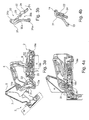
- Weitere Merkmale und Vorteile der Erfindung werden anhand der in den Figuren dargestellten Scharnieren erläutert.
- Im Einzelnen zeigt:
- Figur 1:
- eine perspektivische Ansicht eines Scharniers in einer Zwischenstellung einer mit dem Scharnier ausführbaren Schwenkbewegung,
- Figur 2:
- eine weitere perspektivische Ansicht des Scharniers gemäß
Figur 1 in einer Endstellung, - Figur 3a:
- ein Seitenansicht der Anordnung gemäß
Figur 1 in einem Schnitt in Längsrichtung des Scharniers, - Figur 3b:
- zwei Bauteile der Anordnung gemäß
Figur 3a in Einzelansicht, - Figur 4a:
- das Scharnier gemäß der
Figuren 1 bis 3a im Schnitt in Längsrichtung in einer zur Endstellung gemäßFigur 2 weiteren Endstellung, - Figur 4b:
- zwei Bauteile der Anordnung gemäß
Figur 4a in Einzelansicht, - Figur 5:
- eine Explosionsdarstellung des Scharniers in der Zwischenstellung gemäß
Figur 1 , - Figur 6
- ein erfindungsgemäßes Scharnier im Schnitt in Längsrichtung,
- Figur 7
- zwei Bauteile der Anordnung gemäß
Figur 6 in perspektivischer Einzelansicht und - Figur 8
- die Bauteile gemäß
Figur 7 im Schnitt. - Bei der in den Figuren gezeigten erfindungsgemäßen Anordnung sind für Teile, welche der gezeigten bekannten Anordnung entsprechen, teilweise die gleichen Bezugszeichen verwendet.
- Das in den
Figuren 1 bis 5 gezeigte bekannte Scharnier 1 ist als so genanntes Weitwinkel- bzw. Kreuzgelenkscharnier ausgebildet. Das Scharnier 1 umfasst ein Korpus-Scharnierteil 2, welches an einem Korpus K eines Möbelteils anbringbar ist, und ein Türflügelanschlagteil oder einen Scharniertopf bzw. ein bewegbares Möbelteil-Scharnierteil 3, welches an einem über das Scharnier 1 bewegbar an dem Korpus aufgenommenen Möbelteil M, wie beispielsweise ein Türflügel oder eine Klappe, anbringbar ist. Der Korpus K und das Möbelteil M sind inFigur 3a rein schematisiert ausschnittsweise angedeutet. Die Scharnierteile 2 und 3 können jeweils innenseitig am Korpus bzw. am bewegbaren Möbelteil insbesondere über Schrauben oder über Schnellbefestigungsmittel insbesondere werkzeuglos befestigt werden. Die beiden Scharnierteile 2 und 3 sind durch vier Gelenkarme 4 bis 7 miteinander über einen Gelenkmechanismus zueinander schwenkbar miteinander verbunden. Die Gelenkarme umfassen einen ersten Kreuzarm 4 und einen zweiten Kreuzarm 5 sowie einen ersten Verbindungsarm 6 und einen zweiten Verbindungsarm 7. Dabei weist der Gelenkmechanismus sieben Schwenk-Gelenke 8 bis 14 auf, welche nachfolgend als erstes bis sechstes Gelenk und als Kreuzgelenk bezeichnet sind. Das erste Gelenk 8 dient zur schwenkbaren Aufnahme des ersten Verbindungsarms 6 am Korpus-Scharnierteil 2, wobei der Verbindungsarm 6 über ein zweites Gelenk 9 mit dem ersten Kreuzarm 4 verbunden ist, der wiederum über ein drittes Gelenk 10 gelenkig am Möbelteil-Scharnierteil 3 aufgenommen ist. Am Möbelteil-Scharnierteil 3 ist außerdem über ein viertes Gelenk 11 der zweite Verbindungsarm 7 gelenkig aufgenommen und über ein fünftes Gelenk 12 mit dem zweiten Kreuzarm 5 gelenkig verbunden. Der zweite Kreuzarm 5 ist außerdem am Korpus-Scharnierteil 2 über ein sechstes Gelenk 13 gelenkig am Korpus-Scharnierteil 2 aufgenommen. Des Weiteren sind die beiden Kreuzarme 4, 5 über ein Kreuzgelenk 14 miteinander gelenkig verbunden. Sämtliche Gelenkachsen der Gelenke 8 bis 14 sind parallel bzw. senkrecht zur Schnittebene derFiguren 3a, 4a . - Über den mit dem Scharnier 1 bereitgestellten Gelenkmechanismus kann im montierten Zustand am Möbel damit das bewegbares Möbelteil M aus seiner zum Korpus K geschlossenen Position bzw. der Endstellung des Scharniers 1 gemäß
Figur 4a in eine maximal weit verschwenkte geöffnete Stellung des Möbelteils bzw. in die Endstellung des Scharniers 1 gemäßFigur 2 gebracht werden, was einem maximalen Schwenkwinkel von über 160 Winkelgrade entspricht. Daher wird das Scharnier 1 auch als Weitwinkelscharnier bezeichnet. - Wie aus
Figur 5 hervorgeht, sind die Gelenke 8 bis 14 für deren gelenkige Funktion jeweils mit einem Achsstift 8a bis 14a realisiert, welche in entsprechend passenden Öffnungen bzw. Bohrungen in den miteinander verbundenen Bauteilen aufgenommen sind. - Des Weiteren ist aus
Figur 5 ersichtlich, dass das Korpus-Scharnierteil 2 ein inneres Montageteil 15 und ein darauf bzw. darüber aufsetzbares Aufsetzteil 16 umfasst. Das Korpus-Scharnierteil 2 umfasst außerdem zur Einstellung des montierten Scharniers 1 Verstellmittel, die eine Einstellschraube 17 und ein Verstellelement 18 umfassen. Im Montageteil 15 ist außerdem ein separat einsetzbarer Dämpfer 19, der z. B. als Fluid-Dämpfer ausgebildet ist, einer Dämpferanordnung integriert, die in ihrer Dämpfercharakteristik ein- bzw. verstellbar ist. Der Dämpfer 19 umfasst ein Gehäuse 19a, in dem ein nicht ersichtlicher Kolben verschieblich aufgenommen ist, mit dem eine aus dem Gehäuse 19a herausstehende Kolbenstange 19b verbunden ist. Mit dem Gehäuse 19a ist außen über Klemmbacken 20a ein Bedienbügel 20 verbunden. Die Kolbenstange 19b ist mit dem unteren Ende der Einstellschraube 17 verbunden. - Ein Verbindungsstift 21 dient zur Verbindung des Montageteils 15 und des Aufsetzteils 16.
- Für ein gezieltes Einwirken auf den Dämpfer 19 ist eine Steuerung vorgesehen, die einen mit dem Gehäuse 19a verbundenen Bedienhebel 22 umfasst, der über eine Bohrung 23 im Bedienhebel 22, eine Bohrung 25 im Aufsetzteil 16 und einen die Bohrungen 23 und 25 durchgreifenden Achsstift 24 schwenkbar am Aufsetzteil 16 gelagert ist, mit einer Schwenkachse, die parallel zu den Gelenkachsen 8 bis 14 verläuft. Zur Bewegungskopplung der Schwenkbewegung des Bedienhebels 22 mit der translatorischen Bewegung des Gehäuses 19a ist der Bedienhebel 22 als zweiarmiger Hebel ausgebildet. Der Bedienhebel 22 ist an seinem zum Aufsetzteil 16 zugewandten Ende über einen Achsstift 26 mit dem Bedienbügel 20 über eine weitere Bohrung 28 endseitig am Bedienhebel 22 und eine Bohrung 27 im Bedienbügel 20 gelenkig verbunden. Am vom Aufsetzteil 16 abgewandten Ende ist der Bedienhebel 22 mit einem Eingreifabschnitt in Form einer Profilierung, hier in Form einer zur Längserstreckung seitlich vorstehenden Nase 29, versehen, welche mit einem Führungsabschnitt 30 an einem Führungshebel 31 zeit- bzw. phasenweise zusammenwirkt bzw. ein- und auskuppelbar ist.
- Der Führungsabschnitt 30 im Führungshebel 31 umfasst eine leicht gebogen verlaufende Nut 30a, was insbesondere gemäß der
Figuren 3b und 4b im mittigen Längsschnitt durch den Führungshebel 31 ersichtlich ist, mit einer Nuttiefe, die in etwa der Höhe der vorstehenden Nase 29 entspricht. Die Nut 30a endet geschlossen im Führungshebel 31, wobei zum sicheren und ruckfreien Ein- und Auskuppeln der Nase 29 mit dem Führungsabschnitt 30 die Nut 30a an ihrem offenen Ende sich über einen aufweitenden bzw. von der Seite trichterförmigen Einfädelabschnitt 30b erweitert. Die Nase ist entsprechend für ein sauberes Aus- und Einfädeln bzw. ein Gleiten in der Nut 30a im Schnitt halbseitig konvex und halbseitig flach ausgestaltet. - Anstelle der Führungsnut kann ein endseitig offenes Langloch, ein Einschnitt, eine Kulissenführung usw. ausgebildet sein.
- Der Führungshebel 31 weist am Ende jeweils Bohrungen 31a, 31b auf, über welche der Führungshebel 31 zwischen den Achsstiften 13a und 14a bzw. den entsprechenden Gelenken 13 und 14 eingespannt ist. Damit wird der Führungshebel 31 entsprechend des beim Schwenkvorgang mit dem Scharnier 1 bewegten Teils des zweiten Kreuzarms 5 mitbewegt. Dies wird auch aus den
Figuren 3a und 4a deutlich, wonach der Führungshebel 31 inFigur 3a entsprechend der gezeigten Zwischenstellung in seiner Längsausrichtung in etwa senkrecht zur Längserstreckung des Korpus-Scharnierteils 2 steht und inFigur 4a bei einer Endstellung des Schwenkmechanismus mit dem Scharnier 1 nach rechts um etwas 45 Winkelgrade geneigt ist. Diese Stellungen entsprechen den jeweils dazugehörigen Schwenkstellungen des zweiten Kreuzarms 5. - Grundsätzlich können der Führungsabschnitt bzw. der Führungshebel 31 und der weitere Hebel bzw. der Betätigungshebel 22 an einer anderen Stelle im Scharnier 1 bzw. in anderen Scharnieren vorhanden sein.
- Das Scharnier 1 weist zudem eine Einzuganordnung 32 im ersten Kreuzarm 4 integriert auf, welche auf einem letzten Teilabschnitt der Schwenkbewegung vor Erreichen einer Schließstellung gemäß
Figur 4a über zwei integrierte Spiralfedern 33, 34 und eine Druckplatte 35 bei Erreichen einer vorgebbaren Schwenkstellung des Scharniers 1 dieses selbsttätig in die geschlossene Endstellung gemäßFigur 4a drückt bzw. zieht, wobei die hierfür notwendige Schließkraft durch die beiden vorgespannten Spiralfedern 33, 34 realisiert wird. Dabei wirken die Spiralfedern 33, 34 nach einer Aufhebung einer Blockierung der Einzuganordnung 32, was z. B. beim Schließen eines Möbelteils M an einem Korpus K mit dem Scharnier 1 an einem vorgebbaren Schwenkpunkt erfolgt, so auf die Druckplatte 35, dass diese in Richtung auf den Verbindungsarm 6 verschoben wird und auf diesen einwirkt, so dass ein gedämpftes Schließen des Möbelteils M in die Endstellung gemäßFigur 4a erfolgt. Kurz nach dem Aktivieren der Einzuganordnung 32 wird danach bei der weiteren Schließbewegung durch die Kopplung des Betätigungshebels 22 einerseits mit dem Führungshebel 31 und andererseits mit dem Bedienbügel 20 die Dämpferanordnung 19 ebenfalls aktiviert. - Die Einzuganordnung 32 wird über zwei Steckstifte 36, 37 am Kreuzarm 4 gehalten.
- Beim erneuten Öffnen des am Möbelteil-Scharnierteil 3 angebrachten bewegbaren Möbelteils M relativ zum Korpus K wird die Einzuganordnung 32 wieder in ihre vorgespannte Position gebracht (
Figur 1, 2 ,3a ) und in dieser gehalten, bis bei einer Rückbewegung durch Verschwenken des Scharniers 1 beim Schließen des betreffenden Möbelteils wieder die vorgegebene Einzugsposition erreicht wird. Entsprechend wird die Dämpferanordnung 19 wieder in Bereitschaftsstellung gemäßFigur 1, 2 bzw. 3a gebracht durch Zurückschieben des Gehäuses 19a in die Bereitschaftsstellung durch Einwirken des entsprechend beim Öffnen des Möbelteils M zurückschwenkenden Betätigungshebels 22. - So kann beim Schließen des Möbelteils M beim Verschwenkvorgang trotz der Einzugsautomatik bzw. eines Zuschlagens kein stoßartiges Anschlagen des Möbelteils M am Korpus K stattfinden. Beim Dämpfen der Schließbewegung wird das Gehäuse 19a in Richtung auf ein vorderes Ende der aus dem Gehäuse 19a vorstehenden und positionsfest gehaltenen Kolbenstange 19b bewegt. Diese Bewegung erfolgt gedämpft bzw. gebremst. Während des Dämpfvorgangs wird der Bedienhebel 22 um den Achsstift 24 in der Bohrung 25 gemäß Pfeil P1 in
Figur 3b im Uhrzeigersinn verschwenkt, sodass das Gehäuse 19a relativ zum freien Ende der Kolbenstange 19b gemäß Pfeil P2 inFigur 3a verschoben wird. Beim Koppeln wird die Nase 29 vorne am Bedienhebel 22 in dem Führungsabschnitt 30 bis in die Endstellung gemäßFigur 4a und 4b gebracht. Bei erneutem Öffnen bzw. Verschwenken in die entgegengesetzte Richtung wird durch das Zusammenwirken des Führungshebels 31 und des Bedienhebels 22 das Dämpfergehäuse 19a wieder in die gemäßFigur 3a gezeigte Bereitschaftsstellung zurückgeschoben. -
Figur 6 zeigt ein zum Scharnier 1 erfindungsgemäßes Scharnier 38, welches in der Grundfunktion im Wesentlichen gemäß dem Scharnier 1 entspricht und dementsprechend aufgebaut ist. Das Scharnier 38 umfasst die gleichen Grundbauteile wie das Scharnier 1, insbesondere ein Korpus-Scharnierteil 2 am Korpus K, ein Möbelteil-Scharnierteil 3 am Möbelteil M, Kreuzarme 4, 5, Verbindungsarme 6, 7, einen Dämpfer 19 mit einer Kolbenstange 19b, einen Bedienbügel 20 und einen Führungsabschnitt 30 am Scharnier 38. Nachfolgend ist das Scharnier 38 insbesondere bezüglich der Unterschiede zum Scharnier 1 erläutert. - Gemäß
Figur 6 befindet sich das Scharnier 38 in einem Zustand nahe einer Endstellung des Scharniers 38 bei geschlossenem Möbelteil. Dabei ist ein ausgekuppelter Zustand eines Führungshebels 39 und eines mit diesem zusammenwirkenden Bedienhebels 40 dargestellt. - Der Führungshebel 39 und der Bedienhebel 40 funktionieren im Normalbetrieb entsprechend dem Zusammenwirken des Führungshebels 31 mit dem Bedienhebel 22 gemäß dem Scharnier 1 und sind daher in ihrer Grundgestalt dem Führungshebel 31 bzw. dem Bedienhebel 22 stark angenähert bzw. entsprechend angeordnet.
- Der Führungshebel 39 weist für ein Einfädeln eines vorderen Endbereichs 41 des Bedienhebels 40 in eine Kulisse bzw. Nut 42 am Führungshebel 39 eine Führungsfläche 43 auf, die über die Längserstreckung der Nut 42 an deren zum Endbereichs 41 gerichteten Rand ausgebildet ist. Die Führungsfläche 43 ist so ausgebildet bzw. auf den sich mit dem Schwenken des Bedienhebels 40 mitbewegten Endbereich 41 so abgestimmt, dass bei einer Schwenkstellung des Bedienhebels 40 gemäß Bewegungsrichtung P3 vor einem Einkuppelvorgang des Bedienhebels 40 am Führungshebel 39, wobei sich die Schwenkstellung von einer vorgegebenen funktionsrichtigen Bereitschaftsstellung unterscheidet, den Endbereichs 41 des Bedienhebels 40 und damit diesen selbst in die funktionsrichtige Stellung zum Führungshebel 39 und weiter in die richtige Einkuppelstellung von Bedienhebel 40 und Führungshebel 39 bringt.
- Die Ausrichtung bzw. der Verlauf und/oder die Form der Führungsfläche 43 kann auf eine entsprechende mit dieser zusammenwirkenden Gegenfläche am Endbereichs 41 des Bedienhebels 40 für ein sanftes bzw. gleitendes Zusammenwirken von Bedienhebel 40 und Führungshebel 39 ausgebildet sein, um eine ruckfreie Scharnierbewegung zu gewährleisten.
- Die Führungsfläche 43 kann beispielsweise am vorderen Rand 43a derart gestaltet sein, dass der Endbereichs 41 des Bedienhebels 40 ohne maßgeblichen Widerstand in die Nut 42 einkuppeln kann, wenn eine Scharnierbewegung des Scharniers 38 erfolgt, in welcher der Bedienhebel 40 am Führungshebel 39 einkuppelt. Damit wird ein Dämpfer 19 am Scharnier 38 ausgelöst, so dass die Schließbewegung des nicht dargestellten bewegbaren Möbelteils sanft erfolgt.
Figur 6 zeigt den Bedienhebel 40 im ausgekuppelten Zustand vom Führungshebel 39 bzw. einer daran vorhandenen Kulisse mit der Nut 42. -
- 1
- Scharnier
- 2
- Korpus-Scharnierteil
- 3
- Möbelteil-Scharnierteil
- 4
- Kreuzarm
- 5
- Kreuzarm
- 6
- Verbindungsarm
- 7
- Verbindungsarm
- 8 bis 13
- Gelenk
- 8a bis 14a
- Achsstift
- 14
- Kreuzgelenk
- 15
- Montageteil
- 16
- Aufsetzteil
- 17
- Einstellschraube
- 18
- Verstellelement
- 19
- Dämpfer
- 19a
- Gehäuse
- 19b
- Kolbenstange
- 20
- Bedienbügel
- 20a
- Klemmbacke
- 21
- Verbindungsstift
- 22
- Bedienhebel
- 23
- Bohrung
- 24
- Achsstift
- 25
- Bohrung
- 26
- Achsstift
- 27
- Bohrung
- 28
- Bohrung
- 29
- Nase
- 30
- Führungsabschnitt
- 30a
- Nut
- 30b
- Einfädelabschnitt
- 31
- Führungshebel
- 31a, 31b
- Bohrung
- 32
- Einzuganordnung
- 33, 34
- Spiralfeder
- 35
- Druckplatte
- 36, 37
- Steckstift
- 38
- Scharnier
- 39
- Führungshebel
- 40
- Bedienhebel
- 41
- Endbereich
- 42
- Nut
- 43
- Führungsfläche
- 43a
- Rand
Claims (13)
- Scharnier (38) für ein bewegbares Möbelteil, welches über das Scharnier (38) an einem Korpus eines Möbels aufnehmbar ist, insbesondere Möbelscharnier für eine Tür oder Klappe, wobei das Scharnier (38) ein an dem Korpus anbringbares erstes Anschlagteil (2) aufweist, welches über einen Gelenkmechanismus mit einem am bewegbaren Möbelteil anbringbaren zweiten Anschlagteil (3) verschwenkbar verbunden ist, wobei der Gelenkmechanismus über Gelenkachsen gelagerte Gelenkhebel (4 bis 7) umfasst, und wobei ein auf eine Dämpferanordnung des Scharniers (38) einwirkender weiterer Hebel (40) vorhanden ist, der über eine zu den Gelenkachsen separate Achse schwenkbar aufgenommenen und bei einer bestimmungsgemäßen Schwenkbewegung des Scharniers (38) mit einem Führungsabschnitt (30) am Scharnier (38) zeitweise eingekuppelt ist, wobei im Regelbetrieb des Scharniers (38) der weitere Hebel (40) vor einem Einkuppelvorgang eine vorgegebene Bereitschaftsstellung einnimmt, aus welcher der weitere Hebel (40) am Führungsabschnitt (30) einkuppelt, dadurch gekennzeichnet, dass ein auf den weiteren Hebel (40) abgestimmter Stellabschnitt derart ausgebildet ist, dass der weitere Hebel (40) am Scharnier (38) aus einer Schwenkstellung, die sich vor dem Einkuppelvorgang von der vorgegebenen Bereitschaftsstellung unterscheidet, bei der bestimmungsgemäßen Schwenkbewegung des Scharniers (38) mit dem Stellabschnitt zusammenwirkt, so dass der Stellabschnitt den weiteren Hebel (40) zwangsweise in den eingekuppelten Zustand versetzt.
- Scharnier nach Anspruch 1, dadurch gekennzeichnet, dass ein Anlageabschnitt des weiteren Hebels (40) vorhanden ist, der mit dem Führungsabschnitt (30) einkuppelbar ist, wobei der Stellabschnitt eine auf den Anlageabschnitt abgestimmte Führungsflanke umfasst, welche in einer Bewegungsrichtung des Anlageabschnitts schräg ausgerichtet ist.
- Scharnier nach Anspruch 1 oder Anspruch 2, dadurch gekennzeichnet, dass eine Erstreckung des Stellabschnitts an zumindest eine wesentliche Erstreckung des Führungsabschnitts (30) angepasst ist.
- Scharnier nach einem der vorhergehenden Ansprüche, dadurch gekennzeichnet, dass der Stellabschnitt einen Durchlass für den Anlageabschnitt umfasst, wobei der Durchlass gegenüberliegende Schrägflächen aufweist.
- Scharnier nach einem der vorhergehenden Ansprüche, dadurch gekennzeichnet, dass der weitere Hebel (40) und der Führungsabschnitt derart aufeinander abgestimmt sind, einen Einkupplungszustand zwischen dem weiteren Hebel (40) und dem Führungsabschnitt, wobei sich der Einkupplungszustand bei einer bestimmungsgemäßen Schwenkbewegung des Scharniers (38) in eine erste Schwenkrichtung an einem Einkupplungspunkt der Schwenkbewegung einstellt, bei einer Schwenkbewegung des Scharniers (38) aus dem Einkupplungspunkt heraus in eine zweite Schwenkrichtung, die der ersten Schwenkrichtung entgegengerichtet ist, aufzuheben.
- Scharnier nach einem der vorhergehenden Ansprüche, dadurch gekennzeichnet, dass der weitere Hebel (40) ausgebildet ist, auf einen Abschnitt eines Bauteils einzuwirken, das an dem am Korpus anbringbaren ersten Anschlagteil (2) vorhanden ist.
- Scharnier nach einem der vorhergehenden Ansprüche, dadurch gekennzeichnet, dass der Führungsabschnitt (30) zwischen zwei Gelenkachsen des Scharniers (38) aufgenommen ist.
- Scharnier nach einem der vorhergehenden Ansprüche, dadurch gekennzeichnet, dass der Führungsabschnitt (30) eine zu benachbarten Bereichen erhabene oder vertiefte Führungsbahn umfasst, welche für die zeitweise Einkupplung mit einem Eingriffabschnitt des weiteren Hebels (40) abgestimmt ausgebildet ist.
- Scharnier nach einem der vorhergehenden Ansprüche, dadurch gekennzeichnet, dass der Führungsabschnitt (30) derart vorhanden ist, dass bei einer bestimmungsgemäßen Schwenkbewegung des Scharniers (38) der Führungsabschnitt (30) mitbewegt wird.
- Scharnier nach einem der vorhergehenden Ansprüche, dadurch gekennzeichnet, dass der weitere Hebel (40) an einem der Anschlagteile (2, 3) schwenkbar gelagert ist.
- Scharnier nach einem der vorhergehenden Ansprüche, dadurch gekennzeichnet, dass das Scharnier (38) als Kreuzgelenkscharnier ausgebildet ist.
- Scharnier nach einem der vorhergehenden Ansprüche, dadurch gekennzeichnet, dass das Scharnier (38) als Weitwinkelscharnier ausgebildet ist.
- Möbel mit einem an einem Korpus des Möbels angeschlagenen bewegbaren Möbelteil, insbesondere mit einer Türe oder Klappe, wobei das Möbel ein Scharnier (38) nach einem der vorhergehenden Ansprüche aufweist.
Applications Claiming Priority (1)
| Application Number | Priority Date | Filing Date | Title |
|---|---|---|---|
| DE202013008777.3U DE202013008777U1 (de) | 2013-10-07 | 2013-10-07 | Scharnier für ein Möbelteil und Möbel |
Publications (2)
| Publication Number | Publication Date |
|---|---|
| EP2857621A1 true EP2857621A1 (de) | 2015-04-08 |
| EP2857621B1 EP2857621B1 (de) | 2019-11-20 |
Family
ID=51628057
Family Applications (1)
| Application Number | Title | Priority Date | Filing Date |
|---|---|---|---|
| EP14187250.7A Active EP2857621B1 (de) | 2013-10-07 | 2014-10-01 | Scharnier für ein Möbelteil und Möbel |
Country Status (4)
| Country | Link |
|---|---|
| US (1) | US9528307B2 (de) |
| EP (1) | EP2857621B1 (de) |
| CN (1) | CN104695789B (de) |
| DE (1) | DE202013008777U1 (de) |
Families Citing this family (15)
| Publication number | Priority date | Publication date | Assignee | Title |
|---|---|---|---|---|
| DE102013101040A1 (de) * | 2013-02-01 | 2014-08-07 | Hettich-Oni Gmbh & Co. Kg | Mehrgelenkscharnier mit Dämpfung |
| BR112017021966A2 (pt) * | 2015-04-30 | 2018-07-10 | Arturo Salice S.P.A. | dobradiça para lâminas de móvel que abrem para baixo |
| CN104929470A (zh) * | 2015-07-08 | 2015-09-23 | 常州市零伍壹玖电子有限公司 | 一种用于浴室柜门的液压缓冲阻尼铰链 |
| ITUA20161798A1 (it) * | 2016-03-18 | 2017-09-18 | Salice Arturo Spa | Cerniera con mezzi elastici di apertura per ante di mobili. |
| IT201600083263A1 (it) * | 2016-08-08 | 2018-02-08 | Salice Arturo Spa | Sistema di sollevamento per ante di mobili oscillanti secondo almeno un asse orizzontale. |
| IT201600095316A1 (it) * | 2016-09-22 | 2018-03-22 | C M I Cerniere Mecc Industriali Srl | Dispositivo a cerniera per apparecchi con carica dall'alto |
| DE202017102809U1 (de) * | 2017-05-10 | 2018-08-13 | Grass Gmbh & Co. Kg | Vorrichtung zur Bewegung eines an einem Möbelkorpus eines Möbels aufgenommenen Möbelteils |
| WO2018216564A1 (ja) | 2017-05-24 | 2018-11-29 | スガツネ工業株式会社 | 扉用装置 |
| IT201800006575A1 (it) * | 2018-06-22 | 2019-12-22 | Cerniera decelerata per mobili. | |
| KR101971950B1 (ko) * | 2018-11-20 | 2019-04-24 | 주식회사 이피텍 | 멀티 링크 힌지 장치 |
| DE102019100188A1 (de) * | 2019-01-07 | 2020-07-09 | Grass Gmbh | Vorrichtung zum Bewegen einer Möbelklappe und Möbel |
| AT523757B1 (de) * | 2020-05-07 | 2023-07-15 | Blum Gmbh Julius | Möbelantrieb |
| AT523798B1 (de) * | 2020-05-07 | 2025-03-15 | Blum Gmbh Julius | Möbelantrieb |
| AT524381B1 (de) * | 2020-10-22 | 2022-07-15 | Blum Gmbh Julius | Möbelantrieb zum Bewegen eines relativ zu einem Möbelkorpus bewegbar gelagerten Möbelteiles |
| GB2603002A (en) * | 2021-01-25 | 2022-07-27 | Titus D O O Dekani | Hinge assembly |
Citations (3)
| Publication number | Priority date | Publication date | Assignee | Title |
|---|---|---|---|---|
| WO2011095323A2 (de) * | 2010-02-03 | 2011-08-11 | Grass Gmbh & Co. Kg | Scharnier für ein möbelteil und möbel |
| WO2012136045A1 (zh) * | 2011-04-08 | 2012-10-11 | Ou Fengdi | 一种家具铰链 |
| WO2014118320A1 (de) * | 2013-02-01 | 2014-08-07 | Hettich-Oni Gmbh & Co. Kg | Mehrgelenkscharnier mit dämpfung |
Family Cites Families (49)
| Publication number | Priority date | Publication date | Assignee | Title |
|---|---|---|---|---|
| DE3209900A1 (de) * | 1982-03-18 | 1983-09-22 | Karl Lautenschläger KG, Möbelbeschlagfabrik, 6107 Reinheim | Kreuzgelenkscharnier |
| DE3515907A1 (de) * | 1985-05-03 | 1986-11-06 | Häfele KG, 7270 Nagold | Scharnier, insbesondere moebelscharnier |
| AT392320B (de) * | 1987-12-23 | 1991-03-11 | Blum Gmbh Julius | Weitwinkelscharnier |
| DE3914100C2 (de) * | 1989-04-28 | 1998-07-30 | Lautenschlaeger Mepla Werke | Kreuzgelenkscharnier mit Schließmechanismus |
| IT217648Z2 (it) * | 1989-07-28 | 1992-01-07 | T G N Spa | Cerniera per mobili. con basi non incassate |
| IT229592Y1 (it) * | 1993-01-28 | 1999-01-29 | Ferrari Franco | Cerniera con dispositivo anticesoiamento |
| IT1269279B (it) * | 1994-12-16 | 1997-03-26 | Tgn Spa | Cerniera a scatto per mobili perfezionata |
| US5898977A (en) * | 1997-09-25 | 1999-05-04 | Advantage Manufacturing Corp., Inc. | Non-handed in-line window supporting bracket |
| US6397836B1 (en) * | 2001-02-27 | 2002-06-04 | The Stanley Works | Damped oven door mounting assemblies |
| US6789293B2 (en) * | 2001-09-27 | 2004-09-14 | Mansfield Assemblies Co. | Dampened hinge system for appliance door |
| DE20207036U1 (de) * | 2002-05-03 | 2003-09-18 | Mepla-Werke Lautenschläger GmbH & Co. KG, 64354 Reinheim | Kreuzgelenkscharnier |
| US6986187B2 (en) * | 2002-05-20 | 2006-01-17 | Mansfield Assemblies Co. | Hinge assembly with glide member |
| ITMO20030070A1 (it) * | 2003-03-14 | 2004-09-15 | Arrigo Zetti | Cerniera a scatto perfezionata per elementi di chiusura di vani e simili. |
| DE10333925B4 (de) * | 2003-07-24 | 2007-03-22 | Grass Gmbh | Möbelscharnier mit Öffnungsautomatik, insbesondere für Möbeltüren |
| US6892424B1 (en) * | 2003-08-08 | 2005-05-17 | Mansfield Assemblies Co. | Single link hinge assembly with break-away link |
| US7134169B2 (en) * | 2004-01-15 | 2006-11-14 | Mansfield Assemblies Co. | Hinge assembly and door mounting system including same |
| EP1555372B1 (de) * | 2004-01-16 | 2007-08-01 | Ming-Jeng Lin | Scharniervorrichtung |
| DE202004016396U1 (de) * | 2004-10-21 | 2005-01-05 | Julius Blum Gmbh | Dämpferanordnung |
| WO2006053364A1 (de) * | 2004-11-22 | 2006-05-26 | Julius Blum Gmbh | Scharnier mit dämopfer |
| US7017232B1 (en) * | 2005-05-06 | 2006-03-28 | Priddy Thomas G | Load limiting hinge |
| ITMO20050171A1 (it) * | 2005-07-07 | 2007-01-08 | Tgn Spa | ''cerniera a scatto perfezionata per il sostegno di un elemento di chiusura''. |
| AT502621A1 (de) * | 2005-09-28 | 2007-04-15 | Blum Gmbh Julius | Möbelscharnier |
| KR100828274B1 (ko) * | 2005-11-04 | 2008-05-07 | 풍원공업 주식회사 | 도어 힌지 |
| US20070209654A1 (en) * | 2006-03-07 | 2007-09-13 | Ching-Hsiang Wang | Hinge device of a steam oven door |
| ITBO20060308A1 (it) * | 2006-04-21 | 2007-10-22 | Nuova Star Spa | Cerniera per ante o sportelli |
| ITMI20062232A1 (it) * | 2006-11-22 | 2008-05-23 | Agostino Ferrari Spa | Cerniera con ridotto ingombro per ante a movimento verticale |
| ITBO20070110A1 (it) * | 2007-02-22 | 2008-08-23 | Nuova Star Spa | Cerniera per ante o sportelli. |
| ES2537543T3 (es) * | 2007-05-18 | 2015-06-09 | Faringosi-Hinges S.R.L. | Bisagra para puerta |
| ITBO20070369A1 (it) * | 2007-05-23 | 2008-11-24 | Nuova Star Spa | Cerniera per ante o sportelli |
| DE202007012603U1 (de) * | 2007-09-07 | 2009-01-22 | Hettich-Oni Gmbh & Co. Kg | Türscharnier eines Haushaltsgerätes |
| AT506756B1 (de) * | 2008-04-16 | 2013-03-15 | Grass Gmbh & Co Kg | Möbelscharnier |
| US8443489B2 (en) * | 2009-02-05 | 2013-05-21 | Mansfield Assemblies Co. | Appliance hinge counterbalance assembly |
| ATE521776T1 (de) * | 2009-02-13 | 2011-09-15 | Electrolux Home Prod Corp | OFENTÜRÖFFNUNGS- UND -SCHLIEßVORRICHTUNG |
| US8201304B2 (en) * | 2009-02-25 | 2012-06-19 | General Electric Company | Compliant door hinge |
| IT1393614B1 (it) * | 2009-04-08 | 2012-05-08 | Nuova Star Spa | Cerniera per ante o sportelli |
| JP2010281107A (ja) * | 2009-06-04 | 2010-12-16 | Meiko:Kk | スライドヒンジ用ダンパー |
| US8925542B2 (en) * | 2009-07-21 | 2015-01-06 | Mansfield Assemblies Co. | Slow open and/or slow close hinge assembly and hinge system |
| TWM378960U (en) * | 2009-09-25 | 2010-04-21 | Hu Hua Metal Products Co Ltd | Hinge |
| AT509094B1 (de) * | 2009-12-09 | 2013-07-15 | Blum Gmbh Julius | Möbelscharnier |
| US20110146655A1 (en) * | 2009-12-21 | 2011-06-23 | Whirlpool Corporation | Hydraulic hinge for freestanding appliance |
| US20110146654A1 (en) * | 2009-12-21 | 2011-06-23 | Whirlpool Corporation | Limited load hinge for freestanding appliance |
| WO2012168748A1 (en) * | 2011-06-08 | 2012-12-13 | Faringosi Hinges S.R.L. | Hinges provided with elastic means and dampener |
| ITMI20112035A1 (it) * | 2011-11-09 | 2013-05-10 | Salice Arturo Spa | Cerniera con dispositivo di decelerazione per mobili |
| ITBO20120244A1 (it) * | 2012-05-04 | 2013-11-05 | Nuova Star Spa | Cerniera per ante o sportelli, di elettrodomestici quali forni, lavastoviglie o simili |
| US8833877B2 (en) * | 2012-05-14 | 2014-09-16 | Bsh Home Appliances Corporation | Hinge assembly for domestic appliance |
| US8806718B2 (en) * | 2012-05-23 | 2014-08-19 | Bsh Home Appliances Corporation | Domestic appliance hinge assembly with double linkage |
| US8707519B2 (en) * | 2012-05-23 | 2014-04-29 | Bsh Home Appliances Corporation | Domestic appliance hinge assembly with universal hinge body design |
| CN103061632B (zh) * | 2013-01-10 | 2016-04-06 | 伍志勇 | 带引导装置的铰链 |
| US9316036B2 (en) * | 2013-05-23 | 2016-04-19 | Mansfield Engineered Components, Inc. | Appliance hinge counterbalance assembly with snubber |
-
2013
- 2013-10-07 DE DE202013008777.3U patent/DE202013008777U1/de not_active Expired - Lifetime
-
2014
- 2014-10-01 EP EP14187250.7A patent/EP2857621B1/de active Active
- 2014-10-06 US US14/506,948 patent/US9528307B2/en active Active
- 2014-10-08 CN CN201410858030.6A patent/CN104695789B/zh active Active
Patent Citations (3)
| Publication number | Priority date | Publication date | Assignee | Title |
|---|---|---|---|---|
| WO2011095323A2 (de) * | 2010-02-03 | 2011-08-11 | Grass Gmbh & Co. Kg | Scharnier für ein möbelteil und möbel |
| WO2012136045A1 (zh) * | 2011-04-08 | 2012-10-11 | Ou Fengdi | 一种家具铰链 |
| WO2014118320A1 (de) * | 2013-02-01 | 2014-08-07 | Hettich-Oni Gmbh & Co. Kg | Mehrgelenkscharnier mit dämpfung |
Also Published As
| Publication number | Publication date |
|---|---|
| US20150096147A1 (en) | 2015-04-09 |
| CN104695789A (zh) | 2015-06-10 |
| CN104695789B (zh) | 2017-06-23 |
| US9528307B2 (en) | 2016-12-27 |
| EP2857621B1 (de) | 2019-11-20 |
| DE202013008777U1 (de) | 2015-01-08 |
Similar Documents
| Publication | Publication Date | Title |
|---|---|---|
| EP2857621B1 (de) | Scharnier für ein Möbelteil und Möbel | |
| EP2531683B1 (de) | Scharnier für ein möbelteil und möbel | |
| EP2710211B1 (de) | Möbelantrieb für eine bewegbare möbelklappe | |
| EP2142045B1 (de) | Möbel und vorrichtung zum ausstossen eines möbelteils | |
| AT511587B1 (de) | Bewegliche montageplatte für möbelscharniere | |
| EP3141153B1 (de) | Vorrichtung zum bewegen eines bewegbaren möbelteils in eine öffnungsrichtung in bezug zu einem möbelkorpus eines möbels | |
| EP3132715B1 (de) | Vorrichtung zum bewegen eines bewegbaren möbelteils in eine öffnungsrichtung mit bezug zu einem möbelkorpus eines möbels | |
| DE202015104432U1 (de) | Vorrichtung zum Bewegen eines bewegbaren Möbelteils und Möbel | |
| DE202015104439U1 (de) | Vorrichtung zum Bewegen eines bewegbaren Möbelteils und Möbel | |
| EP2949852B1 (de) | Vorrichtung zum bewegen eines an einem möbelkorpus aufgenommenen möbelteils und möbel | |
| EP3341545A1 (de) | Vorrichtung zum positionieren von zwei schiebetüren und möbel | |
| DE202015104434U1 (de) | Vorrichtung zum Bewegen eines bewegbaren Möbelteils sowie Möbel mit einer Vorrichtung zum Bewegen eines bewegbaren Möbelteils | |
| EP2054574B1 (de) | Möbelscharnier | |
| DE202015104437U1 (de) | Vorrichtung zum Bewegen eines bewegbaren Möbelteils in eine Öffnungsrichtung in Bezug zu einem Möbelkorpus eines Möbels | |
| EP2560520B1 (de) | AUSSTOßER ZUM AUSSTOßEN EINES BEWEGBAREN MÖBELTEILS | |
| EP3132714B1 (de) | Vorrichtung zum bewegen eines bewegbaren möbelteils in eine öffnungsrichtung in bezug zu einem möbelkorpus eines möbels | |
| EP2430272B1 (de) | VORRICHTUNG ZUR SCHLIEßFOLGEREGELUNG | |
| DE102011057063B4 (de) | Vorrichtung für das Steuern der Schließfolge von zweiflügeligen Schwenktüren | |
| EP3350395B1 (de) | Stellantrieb für möbelteile | |
| EP3192956B1 (de) | Deckelsteller | |
| EP2710924B1 (de) | Führungsmittel für die bewegungsführung eines möbelteils | |
| EP2949848A1 (de) | Vorrichtung zum bewegen einer an einem möbelkorpus bewegbar aufgenommenen faltklappe sowie möbel mit einer solchen vorrichtung | |
| EP2559355A1 (de) | Vorrichtung zur Bewegung eines bewegbaren Möbelteils, Führungseinheit und Möbel | |
| EP2267260A1 (de) | Dämpfungs- und Auszugsvorrichtung | |
| WO2016079256A1 (de) | HALTERUNG FÜR EIN SCHLIEßELEMENT |
Legal Events
| Date | Code | Title | Description |
|---|---|---|---|
| PUAI | Public reference made under article 153(3) epc to a published international application that has entered the european phase |
Free format text: ORIGINAL CODE: 0009012 |
|
| 17P | Request for examination filed |
Effective date: 20141001 |
|
| AK | Designated contracting states |
Kind code of ref document: A1 Designated state(s): AL AT BE BG CH CY CZ DE DK EE ES FI FR GB GR HR HU IE IS IT LI LT LU LV MC MK MT NL NO PL PT RO RS SE SI SK SM TR |
|
| AX | Request for extension of the european patent |
Extension state: BA ME |
|
| R17P | Request for examination filed (corrected) |
Effective date: 20151007 |
|
| RBV | Designated contracting states (corrected) |
Designated state(s): AL AT BE BG CH CY CZ DE DK EE ES FI FR GB GR HR HU IE IS IT LI LT LU LV MC MK MT NL NO PL PT RO RS SE SI SK SM TR |
|
| STAA | Information on the status of an ep patent application or granted ep patent |
Free format text: STATUS: EXAMINATION IS IN PROGRESS |
|
| 17Q | First examination report despatched |
Effective date: 20170329 |
|
| RAP1 | Party data changed (applicant data changed or rights of an application transferred) |
Owner name: GRASS GMBH |
|
| GRAP | Despatch of communication of intention to grant a patent |
Free format text: ORIGINAL CODE: EPIDOSNIGR1 |
|
| STAA | Information on the status of an ep patent application or granted ep patent |
Free format text: STATUS: GRANT OF PATENT IS INTENDED |
|
| INTG | Intention to grant announced |
Effective date: 20190708 |
|
| GRAS | Grant fee paid |
Free format text: ORIGINAL CODE: EPIDOSNIGR3 |
|
| GRAA | (expected) grant |
Free format text: ORIGINAL CODE: 0009210 |
|
| STAA | Information on the status of an ep patent application or granted ep patent |
Free format text: STATUS: THE PATENT HAS BEEN GRANTED |
|
| AK | Designated contracting states |
Kind code of ref document: B1 Designated state(s): AL AT BE BG CH CY CZ DE DK EE ES FI FR GB GR HR HU IE IS IT LI LT LU LV MC MK MT NL NO PL PT RO RS SE SI SK SM TR |
|
| REG | Reference to a national code |
Ref country code: GB Ref legal event code: FG4D Free format text: NOT ENGLISH |
|
| REG | Reference to a national code |
Ref country code: CH Ref legal event code: EP |
|
| REG | Reference to a national code |
Ref country code: IE Ref legal event code: FG4D Free format text: LANGUAGE OF EP DOCUMENT: GERMAN |
|
| REG | Reference to a national code |
Ref country code: DE Ref legal event code: R096 Ref document number: 502014013086 Country of ref document: DE |
|
| REG | Reference to a national code |
Ref country code: AT Ref legal event code: REF Ref document number: 1204376 Country of ref document: AT Kind code of ref document: T Effective date: 20191215 |
|
| REG | Reference to a national code |
Ref country code: SE Ref legal event code: TRGR |
|
| REG | Reference to a national code |
Ref country code: NL Ref legal event code: MP Effective date: 20191120 |
|
| REG | Reference to a national code |
Ref country code: LT Ref legal event code: MG4D |
|
| PG25 | Lapsed in a contracting state [announced via postgrant information from national office to epo] |
Ref country code: GR Free format text: LAPSE BECAUSE OF FAILURE TO SUBMIT A TRANSLATION OF THE DESCRIPTION OR TO PAY THE FEE WITHIN THE PRESCRIBED TIME-LIMIT Effective date: 20200221 Ref country code: LT Free format text: LAPSE BECAUSE OF FAILURE TO SUBMIT A TRANSLATION OF THE DESCRIPTION OR TO PAY THE FEE WITHIN THE PRESCRIBED TIME-LIMIT Effective date: 20191120 Ref country code: NO Free format text: LAPSE BECAUSE OF FAILURE TO SUBMIT A TRANSLATION OF THE DESCRIPTION OR TO PAY THE FEE WITHIN THE PRESCRIBED TIME-LIMIT Effective date: 20200220 Ref country code: LV Free format text: LAPSE BECAUSE OF FAILURE TO SUBMIT A TRANSLATION OF THE DESCRIPTION OR TO PAY THE FEE WITHIN THE PRESCRIBED TIME-LIMIT Effective date: 20191120 Ref country code: BG Free format text: LAPSE BECAUSE OF FAILURE TO SUBMIT A TRANSLATION OF THE DESCRIPTION OR TO PAY THE FEE WITHIN THE PRESCRIBED TIME-LIMIT Effective date: 20200220 Ref country code: FI Free format text: LAPSE BECAUSE OF FAILURE TO SUBMIT A TRANSLATION OF THE DESCRIPTION OR TO PAY THE FEE WITHIN THE PRESCRIBED TIME-LIMIT Effective date: 20191120 Ref country code: NL Free format text: LAPSE BECAUSE OF FAILURE TO SUBMIT A TRANSLATION OF THE DESCRIPTION OR TO PAY THE FEE WITHIN THE PRESCRIBED TIME-LIMIT Effective date: 20191120 Ref country code: ES Free format text: LAPSE BECAUSE OF FAILURE TO SUBMIT A TRANSLATION OF THE DESCRIPTION OR TO PAY THE FEE WITHIN THE PRESCRIBED TIME-LIMIT Effective date: 20191120 |
|
| PG25 | Lapsed in a contracting state [announced via postgrant information from national office to epo] |
Ref country code: HR Free format text: LAPSE BECAUSE OF FAILURE TO SUBMIT A TRANSLATION OF THE DESCRIPTION OR TO PAY THE FEE WITHIN THE PRESCRIBED TIME-LIMIT Effective date: 20191120 Ref country code: IS Free format text: LAPSE BECAUSE OF FAILURE TO SUBMIT A TRANSLATION OF THE DESCRIPTION OR TO PAY THE FEE WITHIN THE PRESCRIBED TIME-LIMIT Effective date: 20200320 Ref country code: RS Free format text: LAPSE BECAUSE OF FAILURE TO SUBMIT A TRANSLATION OF THE DESCRIPTION OR TO PAY THE FEE WITHIN THE PRESCRIBED TIME-LIMIT Effective date: 20191120 |
|
| PG25 | Lapsed in a contracting state [announced via postgrant information from national office to epo] |
Ref country code: AL Free format text: LAPSE BECAUSE OF FAILURE TO SUBMIT A TRANSLATION OF THE DESCRIPTION OR TO PAY THE FEE WITHIN THE PRESCRIBED TIME-LIMIT Effective date: 20191120 |
|
| PG25 | Lapsed in a contracting state [announced via postgrant information from national office to epo] |
Ref country code: RO Free format text: LAPSE BECAUSE OF FAILURE TO SUBMIT A TRANSLATION OF THE DESCRIPTION OR TO PAY THE FEE WITHIN THE PRESCRIBED TIME-LIMIT Effective date: 20191120 Ref country code: CZ Free format text: LAPSE BECAUSE OF FAILURE TO SUBMIT A TRANSLATION OF THE DESCRIPTION OR TO PAY THE FEE WITHIN THE PRESCRIBED TIME-LIMIT Effective date: 20191120 Ref country code: PT Free format text: LAPSE BECAUSE OF FAILURE TO SUBMIT A TRANSLATION OF THE DESCRIPTION OR TO PAY THE FEE WITHIN THE PRESCRIBED TIME-LIMIT Effective date: 20200412 Ref country code: EE Free format text: LAPSE BECAUSE OF FAILURE TO SUBMIT A TRANSLATION OF THE DESCRIPTION OR TO PAY THE FEE WITHIN THE PRESCRIBED TIME-LIMIT Effective date: 20191120 Ref country code: DK Free format text: LAPSE BECAUSE OF FAILURE TO SUBMIT A TRANSLATION OF THE DESCRIPTION OR TO PAY THE FEE WITHIN THE PRESCRIBED TIME-LIMIT Effective date: 20191120 |
|
| REG | Reference to a national code |
Ref country code: DE Ref legal event code: R097 Ref document number: 502014013086 Country of ref document: DE |
|
| PG25 | Lapsed in a contracting state [announced via postgrant information from national office to epo] |
Ref country code: SM Free format text: LAPSE BECAUSE OF FAILURE TO SUBMIT A TRANSLATION OF THE DESCRIPTION OR TO PAY THE FEE WITHIN THE PRESCRIBED TIME-LIMIT Effective date: 20191120 Ref country code: SK Free format text: LAPSE BECAUSE OF FAILURE TO SUBMIT A TRANSLATION OF THE DESCRIPTION OR TO PAY THE FEE WITHIN THE PRESCRIBED TIME-LIMIT Effective date: 20191120 |
|
| PLBE | No opposition filed within time limit |
Free format text: ORIGINAL CODE: 0009261 |
|
| STAA | Information on the status of an ep patent application or granted ep patent |
Free format text: STATUS: NO OPPOSITION FILED WITHIN TIME LIMIT |
|
| 26N | No opposition filed |
Effective date: 20200821 |
|
| PG25 | Lapsed in a contracting state [announced via postgrant information from national office to epo] |
Ref country code: SI Free format text: LAPSE BECAUSE OF FAILURE TO SUBMIT A TRANSLATION OF THE DESCRIPTION OR TO PAY THE FEE WITHIN THE PRESCRIBED TIME-LIMIT Effective date: 20191120 Ref country code: PL Free format text: LAPSE BECAUSE OF FAILURE TO SUBMIT A TRANSLATION OF THE DESCRIPTION OR TO PAY THE FEE WITHIN THE PRESCRIBED TIME-LIMIT Effective date: 20191120 |
|
| REG | Reference to a national code |
Ref country code: CH Ref legal event code: PL |
|
| PG25 | Lapsed in a contracting state [announced via postgrant information from national office to epo] |
Ref country code: LU Free format text: LAPSE BECAUSE OF NON-PAYMENT OF DUE FEES Effective date: 20201001 Ref country code: MC Free format text: LAPSE BECAUSE OF FAILURE TO SUBMIT A TRANSLATION OF THE DESCRIPTION OR TO PAY THE FEE WITHIN THE PRESCRIBED TIME-LIMIT Effective date: 20191120 |
|
| REG | Reference to a national code |
Ref country code: BE Ref legal event code: MM Effective date: 20201031 |
|
| PG25 | Lapsed in a contracting state [announced via postgrant information from national office to epo] |
Ref country code: FR Free format text: LAPSE BECAUSE OF NON-PAYMENT OF DUE FEES Effective date: 20201031 |
|
| PG25 | Lapsed in a contracting state [announced via postgrant information from national office to epo] |
Ref country code: LI Free format text: LAPSE BECAUSE OF NON-PAYMENT OF DUE FEES Effective date: 20201031 Ref country code: CH Free format text: LAPSE BECAUSE OF NON-PAYMENT OF DUE FEES Effective date: 20201031 Ref country code: BE Free format text: LAPSE BECAUSE OF NON-PAYMENT OF DUE FEES Effective date: 20201031 |
|
| PG25 | Lapsed in a contracting state [announced via postgrant information from national office to epo] |
Ref country code: IE Free format text: LAPSE BECAUSE OF NON-PAYMENT OF DUE FEES Effective date: 20201001 |
|
| PGFP | Annual fee paid to national office [announced via postgrant information from national office to epo] |
Ref country code: SE Payment date: 20210929 Year of fee payment: 8 |
|
| PGFP | Annual fee paid to national office [announced via postgrant information from national office to epo] |
Ref country code: GB Payment date: 20211004 Year of fee payment: 8 |
|
| PG25 | Lapsed in a contracting state [announced via postgrant information from national office to epo] |
Ref country code: TR Free format text: LAPSE BECAUSE OF FAILURE TO SUBMIT A TRANSLATION OF THE DESCRIPTION OR TO PAY THE FEE WITHIN THE PRESCRIBED TIME-LIMIT Effective date: 20191120 Ref country code: MT Free format text: LAPSE BECAUSE OF FAILURE TO SUBMIT A TRANSLATION OF THE DESCRIPTION OR TO PAY THE FEE WITHIN THE PRESCRIBED TIME-LIMIT Effective date: 20191120 Ref country code: CY Free format text: LAPSE BECAUSE OF FAILURE TO SUBMIT A TRANSLATION OF THE DESCRIPTION OR TO PAY THE FEE WITHIN THE PRESCRIBED TIME-LIMIT Effective date: 20191120 |
|
| PG25 | Lapsed in a contracting state [announced via postgrant information from national office to epo] |
Ref country code: MK Free format text: LAPSE BECAUSE OF FAILURE TO SUBMIT A TRANSLATION OF THE DESCRIPTION OR TO PAY THE FEE WITHIN THE PRESCRIBED TIME-LIMIT Effective date: 20191120 |
|
| REG | Reference to a national code |
Ref country code: SE Ref legal event code: EUG |
|
| GBPC | Gb: european patent ceased through non-payment of renewal fee |
Effective date: 20221001 |
|
| PG25 | Lapsed in a contracting state [announced via postgrant information from national office to epo] |
Ref country code: SE Free format text: LAPSE BECAUSE OF NON-PAYMENT OF DUE FEES Effective date: 20221002 |
|
| PG25 | Lapsed in a contracting state [announced via postgrant information from national office to epo] |
Ref country code: GB Free format text: LAPSE BECAUSE OF NON-PAYMENT OF DUE FEES Effective date: 20221001 |
|
| REG | Reference to a national code |
Ref country code: DE Ref legal event code: R082 Ref document number: 502014013086 Country of ref document: DE Representative=s name: RAVENSPAT PATENTANWAELTE PARTNERSCHAFT MBB, DE |
|
| PGFP | Annual fee paid to national office [announced via postgrant information from national office to epo] |
Ref country code: DE Payment date: 20251024 Year of fee payment: 12 |
|
| PGFP | Annual fee paid to national office [announced via postgrant information from national office to epo] |
Ref country code: AT Payment date: 20251027 Year of fee payment: 12 |
|
| PGFP | Annual fee paid to national office [announced via postgrant information from national office to epo] |
Ref country code: IT Payment date: 20251015 Year of fee payment: 12 |