EP2857233A1 - Attelage pour véhicules automobiles - Google Patents
Attelage pour véhicules automobiles Download PDFInfo
- Publication number
- EP2857233A1 EP2857233A1 EP20140181703 EP14181703A EP2857233A1 EP 2857233 A1 EP2857233 A1 EP 2857233A1 EP 20140181703 EP20140181703 EP 20140181703 EP 14181703 A EP14181703 A EP 14181703A EP 2857233 A1 EP2857233 A1 EP 2857233A1
- Authority
- EP
- European Patent Office
- Prior art keywords
- module according
- gear
- swivel module
- output
- piece
- Prior art date
- Legal status (The legal status is an assumption and is not a legal conclusion. Google has not performed a legal analysis and makes no representation as to the accuracy of the status listed.)
- Withdrawn
Links
Images


Classifications
-
- B—PERFORMING OPERATIONS; TRANSPORTING
- B60—VEHICLES IN GENERAL
- B60D—VEHICLE CONNECTIONS
- B60D1/00—Traction couplings; Hitches; Draw-gear; Towing devices
- B60D1/01—Traction couplings or hitches characterised by their type
- B60D1/06—Ball-and-socket hitches, e.g. constructional details, auxiliary devices, their arrangement on the vehicle
-
- B—PERFORMING OPERATIONS; TRANSPORTING
- B60—VEHICLES IN GENERAL
- B60D—VEHICLE CONNECTIONS
- B60D1/00—Traction couplings; Hitches; Draw-gear; Towing devices
- B60D1/24—Traction couplings; Hitches; Draw-gear; Towing devices characterised by arrangements for particular functions
- B60D1/246—Traction couplings; Hitches; Draw-gear; Towing devices characterised by arrangements for particular functions for actuating the hitch by powered means
-
- B—PERFORMING OPERATIONS; TRANSPORTING
- B60—VEHICLES IN GENERAL
- B60D—VEHICLE CONNECTIONS
- B60D1/00—Traction couplings; Hitches; Draw-gear; Towing devices
- B60D1/48—Traction couplings; Hitches; Draw-gear; Towing devices characterised by the mounting
- B60D1/485—Traction couplings; Hitches; Draw-gear; Towing devices characterised by the mounting mounted by means of transversal members attached to the frame of a vehicle
-
- B—PERFORMING OPERATIONS; TRANSPORTING
- B60—VEHICLES IN GENERAL
- B60D—VEHICLE CONNECTIONS
- B60D1/00—Traction couplings; Hitches; Draw-gear; Towing devices
- B60D1/48—Traction couplings; Hitches; Draw-gear; Towing devices characterised by the mounting
- B60D1/54—Traction couplings; Hitches; Draw-gear; Towing devices characterised by the mounting collapsible or retractable when not in use, e.g. hide-away hitches
-
- B—PERFORMING OPERATIONS; TRANSPORTING
- B60—VEHICLES IN GENERAL
- B60D—VEHICLE CONNECTIONS
- B60D1/00—Traction couplings; Hitches; Draw-gear; Towing devices
- B60D1/58—Auxiliary devices
- B60D1/62—Auxiliary devices involving supply lines, electric circuits, or the like
-
- F—MECHANICAL ENGINEERING; LIGHTING; HEATING; WEAPONS; BLASTING
- F16—ENGINEERING ELEMENTS AND UNITS; GENERAL MEASURES FOR PRODUCING AND MAINTAINING EFFECTIVE FUNCTIONING OF MACHINES OR INSTALLATIONS; THERMAL INSULATION IN GENERAL
- F16H—GEARING
- F16H1/00—Toothed gearings for conveying rotary motion
- F16H1/28—Toothed gearings for conveying rotary motion with gears having orbital motion
- F16H1/46—Systems consisting of a plurality of gear trains each with orbital gears, i.e. systems having three or more central gears
Definitions
- the invention relates to a swivel module for a trailer hitch for motor vehicles according to the preamble of claim 1.
- the known trailer hitch comprises a pivotally mounted, cranked coupling rod, which is drivable by an electric motor via a planetary gear (planetary gear).
- the coupling rod also called coupling hook, from a rest position into an operating position about a pivot axis, which is identical to the axis of the epicyclic gear, pivotable and lockable in the end positions.
- the planetary gear is formed as a three-membered planetary gear, which has a driven sun gear, with this planetary gears in mesh and a standing with the planetary gears engaging ring gear.
- the planetary gears are mounted on stationary or fixed housing bolts, the ring gear is connected to a flange of the coupling hook, thus forming the output of the planetary gear.
- the well-known planetary gear works at festditionem planet carrier with a stationary translation between the sun and ring gear and has at a reverse drive, ie from the ring gear on the sun gear on no self-locking. For this reason, the coupling rod is locked via an axially displaceable locking pin in their end positions.
- the planetary gear between electromotive drive and output for a coupling hook is designed as a Wolfrom gear.
- a Wolfrom gear or Wolfrom set is known from the prior art, in particular the relevant literature as Wolfromsches Umlaufweggetriebe and is also referred to as a reduced planetary gear.
- the Wolfrom gearbox With the Wolfrom gearbox on the one hand very high translations, d. H.
- the Wolfrom gearbox is self-locking in overrun mode and thus acts as a backstop.
- the coupling hook in particular its ball head, can be loaded by a trailer load during the pivoting movement without a reversal of the drive direction occurring.
- the coupling of a trailer is advantageously supported and facilitated.
- the Wolfrom gear is accommodated in a housing and comprises a drivable sun gear, planet gears, a first fixed ring gear and a second movable ring gear, which forms the output member.
- a compact drive with a very high gear ratio is possible from the sun gear to the movable ring gear.
- the output member or the movable ring gear is connected via at least one intermediate member with the pivotable coupling hook.
- the formation of the intermediate member includes at least two variants for the representation of the pivoting process.
- the at least one intermediate member is formed as an adapter piece which is arranged coaxially to the transmission axis and rotatably mounted in the housing.
- the output member of the Wolfrom set can be easily connected to the coupling hook and pivotal movement of the coupling hook can be effected.
- the intermediate member comprises a coaxially to the transmission axis rotatably arranged drive piece and a pivotally and tiltably formed output piece, wherein the output piece is connected via a rotary joint with the drive piece. Due to the swivel joint, it is possible to superimpose a tilting movement on the driven piece and thus also on the coupling hook, in addition to the pivoting movement.
- the rotary joint comprises a driven-side cross piece, which has four each offset by 90 ° against each other arranged pivot pin or two pairs of pivot pins, and a drive-side fork piece, in which two arranged on a common longitudinal axis pivot pin engage.
- the cross piece according to the invention corresponds to the cross piece of a per se bekanten universal joint, also called universal joint, and the fork corresponds to one of the joint forks of a universal joint.
- the longitudinal axis of the output or cross piece with respect to the longitudinal axis of the drive or fork piece is tilted.
- the second pair of pivot pins engages with a common longitudinal axis in a bearing ring, whose longitudinal and rotational axis is arranged obliquely to the transmission axis.
- the bearing ring thus corresponds to the second yoke of a universal joint, but does not form a driven member, but rather forces the rotatably connected thereto pivot pin on a revolving plane, which obliquely to the transmission axis, d. H. in a defined angle, the so-called tilt angle is arranged. This is the output or cross piece during the pivoting movement additionally imposed a tilting movement.
- the bearing ring is rotatably mounted about its longitudinal axis in the housing and supported in its oblique position.
- the output or cross piece is positively connected to the output for the coupling hook.
- the output for the coupling hook on a mounting flange which is releasably connected to the crosspiece.
- About the mounting flange introduced at the output forces (trailer load) are introduced via the rotary joint in the housing when a coupling hook is attached to the output.
- the mounting flange is sealed by a cover capsule relative to the housing, d. H.
- the capsule bridges the relative movement between pivoting and tilting flange and stationary housing and thus protects the swivel joint from dust and dirt from the outside.
- a conically formed fastening pin is arranged, preferably cast, on the housing.
- About the mounting pin gearbox can be attached to the vehicle with output for the coupling hook and electric motor drive;
- About the mounting pin the trailer load is introduced into the vehicle structure.
- the Wolfrom transmission is drivable via a drive shaft on which the sun gear, a pinion and a locking disk are arranged rotationally fixed.
- the pinion is part of a translation stage between the electromotive drive and transmission input, while the locking disc is part of a locking mechanism.
- the locking disk can be blocked via a preferably electromagnetically actuated locking pin. This makes it possible to mechanically lock the drive side of the Wolfrom transmission, which is basically not necessary because of the self-locking, but is advantageous in a dynamic vibration stress of the output by the coupling hook.
- the swivel module is used as a trailer hitch in conjunction with a form-fitting, force-fitting or cohesively mounted coupling hook.
- the swivel module can be prefabricated individually or together with the coupling hook. It can be prefabricated connected to a trailer crossmember, which is fixed to a motor vehicle. Also, the trailer cross member may be prefabricated with the swivel module and the coupling hook for mounting to a motor vehicle.
- the swivel module can be fixed directly or by means of a connector to the trailer cross member.
- the trailer cross member is fastened to the body of the motor vehicle by means of longitudinal members or the like fastened thereto, e.g. screwed.
- the swivel module can be configured to be electrically operated by means of a push-button or switch or else wirelessly. Furthermore, a control is provided for operating the pivoting process, which monitors the pivoting operation, precludes incorrect operation and, in addition, ensures that in the event of obstacles, in particular limbs, no pinching situation can occur. An overload of the swivel module or its drive is also effectively prevented.
- Fig. 1 shows a schematic representation of a Wolfrom gear 1, ie a reduced planetary gear, as it is known per se from the prior art.
- the Wolfrom gear 1 is characterized by particularly high ratios and low efficiency, which leads to self-locking.
- the Wolfrom gear 1 comprises a sun gear 2, planetary gears 3, a first fixed ring gear 4 and a second movable ring gear 5.
- the planet gears 3 are on the one hand with the driving sun gear 2 and on the other hand both with the fixed ring gear 4 and with the rotatable ring gear fifth in meshing.
- the Wolfrom gear 1, which is the torque transmission from an electric motor drive (not shown here) on a coupling hook (not shown here), is designed so that in a reversal of the drive (overrun) self-locking occurs.
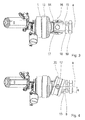
- Fig. 2 shows an electric motor 6 designed as an electric motor drive for the tungsten gear 1 (see. Fig. 1 ) of a trailer hitch 7.
- the Wolfrom transmission 1 also referred to below as transmission 1, has an end face outstanding drive shaft 8, on which a pinion 9, a locking plate 10 with Recesses 10a and - what is not visible - the sun gear 2 (see. Fig. 1 ) are arranged rotationally fixed.
- the electric motor 6 has a motor shaft 6a, which drives the pinion 9.
- a blocking magnet 11 has an extendable latching pin 12, which engages in the recesses 10a of the locking disk 10 and thus blocks the drive shaft 8.
- the mechanical locking by a positive connection between locking pin 12 and locking disc 10 is only when the coupling hook of the trailer hitch 7 in an end position (see. Fig. 8a, 8c ) is located.
- the Wolfrom gear 1 is self-locking, but creeping of the gear may occur under load vibration - hence, the mechanical interlock is provided to maintain the end positions of the coupling hook.
- Fig. 3 shows the output side of the Wolfrom gear 1, the second rotatable ring gear 5 (see. Fig. 1 ) is supported via a bearing 13 against a housing, not shown.
- the transmission axis is designated by a.
- the second ring gear is connected to a driven piece 14, which is designed as a fork piece 14.
- With the fork piece 14 is a cross piece 15 via a pivot pin 16 (see. Figure 5 ), indicated by a dashed line 16, articulated.
- the pivot pin 16 is also referred to as the first pair of pivot pins 16.
- the crosspiece 15 has a second 90 ° relative to the first offset joint pin pair 17.
- the cross piece 15 according to the invention is similar to the cross piece of a universal joint, also called cardan joint.
- the crosspiece 15 has at its output-side end a polygon 18 and a fastening nut 19.
- the polygon 18 (polygon) is used for the positive reception of the coupling hook, not shown here, which will be explained in more detail below. Due to the pivot connection between crosspiece 15 and fork 14, the torque output from the second ring gear is transmitted to the polygon 18.
- Fig. 4 shows the output side of the Wolfrom gear 1 - as in Fig. 3 shown - but in addition to a bearing ring 20 which is arranged obliquely to the transmission axis a and connected via the second pair of pivot pins 17 with the crosspiece 15.
- the bearing ring 20 is rotatably supported in its oblique position in a housing, not shown here, ie it is to a relative to the transmission axis a inclined axis b rotatably, which includes a tilt angle ⁇ with the transmission axis a.
- Fig. 5 shows the transmission 1 with its input and output side and one with the crosspiece 15 by means of the polygon 18 and the mounting nut 19 positively and rotationally fixed coupling hook 21 (shown incomplete).
- the drive shaft 8 with pinion 9 and sun gear 2, the planetary gears 3 and the first and the second ring gear 4, 5 clearly visible.
- the planet gears 3 are mounted on planet pins and rotating planet carrier (without reference number).
- the transmission 1 is received by a transmission housing 22, on which on the one hand, the first ring gear 4 is supported and against which the second ring gear 5 is mounted on the bearing 13.
- the coupling hook 21 has a mounting flange 21 a, which - as mentioned above - is firmly connected to the front end 15 a of the crosspiece 15.
- a Abdeckkapsel 25 or sealing collar attached which slidably rests on the bearing housing 23 and thus during the entire pivoting and tilting movement of the coupling hook 21 causes a seal of the interior. This prevents dirt or dust from contaminating the inside of bearings and joints.
- Fig. 6 shows an overall view of the trailer hitch 7, which is releasably secured by means of a support member 30 to a vehicle-side frame 31.
- Clutch hook 21 is on its mounting flange 21 a to the trailer hitch 7 - as in Fig. 5 shown in more detail - attached and has at the other end to a ball head 21 b, which can be coupled with a (not shown) coupling counterpart.
- Fig. 7 shows the trailer hitch 7 with a conical mounting pin 32, which preferably integrally with the gear housing 22 (see. Fig. 5 ) is formed and can be secured by means of a fastening nut 33 and a disc 34 on the support member 30.
- a fastening nut 33 and a disc 34 on the support member 30.
- Fig. 8a, Fig. 8b and Fig. 8c show the movement during pivoting of the coupling hook 21 from his in Fig. 8a shown operating position in his in Fig. 8c shown rest position.
- the pivot axis a corresponds to the transmission axis a, as in FIG. 3 and FIG. 4 is shown.
- the coupling hook 21 is pivoted from the operating position by 90 °, it is superimposed on a tilting movement, wherein the maximum tilt angle is denoted by ⁇ and can be about 18 °.
- the maximum tilt angle ⁇ is in the middle position according to Fig. 8b reached.
- the coupling hook 21 continues in the direction of rest according to Fig. 8c pivoted, the tilt angle ⁇ is reduced to zero; the coupling hook 21 is in the rest position by 180 ° relative to the operating position according to Fig. 8a pivoted.
- Fig. 9a, Fig. 9b and Fig. 9c show the pivoting process with superimposed tilting movement in reverse order, ie from the rest position according to Fig. 9a in the operating position according to Fig. 9c , Again, the maximum tilt angle ⁇ after pivoting by 90 ° in the middle position according to Fig. 9b reached.
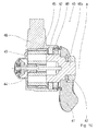
- Fig. 10 shows a second embodiment of the invention, a trailer hitch 40 with a pivotable about the transmission axis a coupling hook 41 (shown incomplete).
- a Wolfrom gear 43 is received, which corresponds to the Wolfrom gear 1 of the first embodiment.
- the drive is also electromotive (not shown) and via the sun gear 44; the output is via the second movable ring gear 45.
- An adapter piece 46 is coaxial with the transmission axis a rotatably disposed in the housing 42 and fixedly connected to the second ring gear 45.
- the adapter piece 46 has a pin 46a on which by means of a fastening nut 47 of the coupling hook 41 is rotatably attached.
- a rotary joint with cross piece is missing - thus eliminating a superimposed tilting movement.
- the coupling hook 41 thus performs only a pure pivoting movement about the transmission axis a.
- the use of the Wolfrom gear 43 is also advantageous in this embodiment as in the first embodiment, as this - as already mentioned above - a very high gear ratio and thus a high torque on the adapter piece 46 can be achieved.
- overrun ie when loaded on the coupling hook 41 by a trailer load on self-locking.
- the trailer hitch 40 thus basically does not need a locking device, which, however, is also provided here due to vibration stresses, according to the first embodiment.
- the trailer hitch 40 has - analogous to the first embodiment - a conical mounting pin 48, which allows attachment to the vehicle.
- FIG. 11a, 11b and 11c show the sequence of pivotal movement of the coupling hook 41 of the trailer hitch 40 (second embodiment).
- Fig. 11 a shows the coupling hook 41 in the operating position, the ball head 41 a points upward, the pivot axis, which corresponds to the transmission axis, is denoted by a.
- Fig. 11b shows the coupling hook 41, pivoted 90 ° about the pivot axis a.
- the ball head 41 a is here in its lowest position.
- Fig. 11c shows the coupling hook 41 after a pivoting 180 ° from the operating position to the rest position.
- the ball head 41 a shows down here.
Applications Claiming Priority (1)
| Application Number | Priority Date | Filing Date | Title |
|---|---|---|---|
| DE102013220024.2A DE102013220024A1 (de) | 2013-10-02 | 2013-10-02 | Anhängerkupplung für Kraftfahrzeuge |
Publications (1)
| Publication Number | Publication Date |
|---|---|
| EP2857233A1 true EP2857233A1 (fr) | 2015-04-08 |
Family
ID=51383618
Family Applications (1)
| Application Number | Title | Priority Date | Filing Date |
|---|---|---|---|
| EP20140181703 Withdrawn EP2857233A1 (fr) | 2013-10-02 | 2014-08-21 | Attelage pour véhicules automobiles |
Country Status (2)
| Country | Link |
|---|---|
| EP (1) | EP2857233A1 (fr) |
| DE (1) | DE102013220024A1 (fr) |
Cited By (2)
| Publication number | Priority date | Publication date | Assignee | Title |
|---|---|---|---|---|
| CN113524993A (zh) * | 2021-05-20 | 2021-10-22 | 浙江致优汽车科技有限公司 | 可自锁的电动拖车钩装置 |
| EP4194232A1 (fr) * | 2021-12-10 | 2023-06-14 | Brink Towing Systems B.V. | Agencement de crochet de remorquage |
Families Citing this family (1)
| Publication number | Priority date | Publication date | Assignee | Title |
|---|---|---|---|---|
| DE102018124549A1 (de) * | 2018-10-04 | 2020-04-09 | Westfalia-Automotive Gmbh | Anhängekupplung |
Citations (5)
| Publication number | Priority date | Publication date | Assignee | Title |
|---|---|---|---|---|
| WO1997010111A1 (fr) * | 1995-09-13 | 1997-03-20 | Cartron Fahrzeugteile Gmbh | Dispositif d'attelage de remorque pour vehicules automobiles |
| EP1504928A1 (fr) | 2003-08-08 | 2005-02-09 | Westfalia Automotive GmbH & Co. KG | Attache remorque |
| DE102006037675A1 (de) * | 2006-08-11 | 2008-02-21 | Paragon Ag | Anhängerkupplung für Kraftfahrzeuge |
| DE102009045290A1 (de) * | 2009-10-02 | 2011-04-07 | Zf Friedrichshafen Ag | Taumelkugelgelenk |
| DE102009049271A1 (de) * | 2009-10-06 | 2011-04-07 | Imo Holding Gmbh | Stegloses Umlaufrädergetriebe |
Family Cites Families (6)
| Publication number | Priority date | Publication date | Assignee | Title |
|---|---|---|---|---|
| DE10350040A1 (de) * | 2003-10-27 | 2005-05-25 | Robert Bosch Gmbh | Getriebe-Antriebseinheit |
| DE102005056217A1 (de) * | 2005-11-25 | 2007-06-06 | Jaeger Cartronix Gmbh | Antriebseinheit für eine Anhängerkupplung |
| DE102006033031B4 (de) * | 2006-07-14 | 2008-07-24 | Paragon Ag | Anhängerkupplung für Kraftfahrzeuge |
| DE102008018739A1 (de) * | 2008-04-14 | 2009-10-15 | Trw Automotive Gmbh | Fahrzeugseitige Kupplungsbaugruppe einer Anhängerkupplung |
| DE102009015916A1 (de) * | 2009-03-25 | 2010-10-07 | Scambia Industrial Developments Aktiengesellschaft | Anhängekupplung |
| DE102011014882A1 (de) * | 2011-03-23 | 2012-09-27 | Westfalia-Automotive Gmbh | Anhängekupplung |
-
2013
- 2013-10-02 DE DE102013220024.2A patent/DE102013220024A1/de not_active Ceased
-
2014
- 2014-08-21 EP EP20140181703 patent/EP2857233A1/fr not_active Withdrawn
Patent Citations (5)
| Publication number | Priority date | Publication date | Assignee | Title |
|---|---|---|---|---|
| WO1997010111A1 (fr) * | 1995-09-13 | 1997-03-20 | Cartron Fahrzeugteile Gmbh | Dispositif d'attelage de remorque pour vehicules automobiles |
| EP1504928A1 (fr) | 2003-08-08 | 2005-02-09 | Westfalia Automotive GmbH & Co. KG | Attache remorque |
| DE102006037675A1 (de) * | 2006-08-11 | 2008-02-21 | Paragon Ag | Anhängerkupplung für Kraftfahrzeuge |
| DE102009045290A1 (de) * | 2009-10-02 | 2011-04-07 | Zf Friedrichshafen Ag | Taumelkugelgelenk |
| DE102009049271A1 (de) * | 2009-10-06 | 2011-04-07 | Imo Holding Gmbh | Stegloses Umlaufrädergetriebe |
Cited By (2)
| Publication number | Priority date | Publication date | Assignee | Title |
|---|---|---|---|---|
| CN113524993A (zh) * | 2021-05-20 | 2021-10-22 | 浙江致优汽车科技有限公司 | 可自锁的电动拖车钩装置 |
| EP4194232A1 (fr) * | 2021-12-10 | 2023-06-14 | Brink Towing Systems B.V. | Agencement de crochet de remorquage |
Also Published As
| Publication number | Publication date |
|---|---|
| DE102013220024A1 (de) | 2015-04-02 |
Similar Documents
| Publication | Publication Date | Title |
|---|---|---|
| DE3430067C1 (de) | Gelenkwelle | |
| EP3116735B1 (fr) | Agencement d'axe d'entraînement | |
| DE102011050440B3 (de) | Selbsttätig schaltende Kupplung für eine Kraftfahrzeug-Außenspiegelverstellung | |
| WO2015185036A1 (fr) | Engrenage planétaire | |
| DE102011115227A1 (de) | Doppelkupplungseinrichtung | |
| DE10157085A1 (de) | Stabilisatoranordnung für ein Kraftfahrzeug | |
| DE2734568A1 (de) | Gelenkbeschlag fuer sitze mit verstellbarer rueckenlehne, insbesondere kraftfahrzeugsitze | |
| EP2857233A1 (fr) | Attelage pour véhicules automobiles | |
| DE102007043032B4 (de) | Vorrichtung zum Kuppeln einer Gelenkwelle mit einer Zapfwelle eines Traktors | |
| DE60118263T2 (de) | Antriebswelle aus Aluminium mit Gleichlaufgelenk | |
| EP0228617A2 (fr) | Dispositif d'entraînement pour des zones, entraînées au choix, d'un arbre de support d'un véhicule à moteur | |
| EP0949106B1 (fr) | Boíte de vitesses pour véhicules à moteur déplacé hors du plan central longitudinal | |
| EP3706531B1 (fr) | Système de liaison d'arbre de prise de force côté véhicule et côté équipement ainsi que dispositif de liaison d'arbre de prise de force présentant ces deux systèmes de liaison d'arbre de prise de force | |
| EP1608540A1 (fr) | Montant reglable en hauteur pour semi-remorque ou similaire | |
| DE2110434C3 (de) | Zahnräderwechselgetriebe in Gruppenbauart für Kraftfahrzeuge mit einem Zentralrohrrahmen und insbesondere mit einem Mehrachsantrieb | |
| DE3138208A1 (de) | "kraftuebertragungseinrichtung fuer kraftfahrzeuge, insbesondere schlepper | |
| DE1555953C3 (de) | Antriebseinrichtung für wahlweise In Zwei-Rad- oder Vier-Rad-Antrieb zu schaltende Kraftfahrzeuge, insbesondere Mähdrescher | |
| DE4206085A1 (de) | Hydromechanisches antriebsaggregat fuer den hydrostatischen fahrantrieb eines fahrzeugs | |
| WO2009027410A1 (fr) | Dispositif d'entraînement | |
| DE3920934A1 (de) | Anhaengereigene antriebseinrichtung | |
| WO2005111467A1 (fr) | Transmission a demultiplication harmonique, notamment concue pour une direction assistee d'un systeme de direction de vehicule | |
| EP1101964A1 (fr) | Accouplement de surcharge | |
| DE102016216790B4 (de) | Umlaufrädergetriebe, nämlich Stirnraddifferentialgetriebe oder Reduktionsvorstufe hierzu | |
| DE3109622A1 (de) | Servolenkvorrichtung fuer kraftfahrzeuge | |
| EP3684639A1 (fr) | Unité carter et ensemble tourillon |
Legal Events
| Date | Code | Title | Description |
|---|---|---|---|
| PUAI | Public reference made under article 153(3) epc to a published international application that has entered the european phase |
Free format text: ORIGINAL CODE: 0009012 |
|
| 17P | Request for examination filed |
Effective date: 20140821 |
|
| AK | Designated contracting states |
Kind code of ref document: A1 Designated state(s): AL AT BE BG CH CY CZ DE DK EE ES FI FR GB GR HR HU IE IS IT LI LT LU LV MC MK MT NL NO PL PT RO RS SE SI SK SM TR |
|
| AX | Request for extension of the european patent |
Extension state: BA ME |
|
| STAA | Information on the status of an ep patent application or granted ep patent |
Free format text: STATUS: THE APPLICATION IS DEEMED TO BE WITHDRAWN |
|
| 18D | Application deemed to be withdrawn |
Effective date: 20151009 |