EP2857233A1 - Towbar for motor vehicles - Google Patents
Towbar for motor vehicles Download PDFInfo
- Publication number
- EP2857233A1 EP2857233A1 EP20140181703 EP14181703A EP2857233A1 EP 2857233 A1 EP2857233 A1 EP 2857233A1 EP 20140181703 EP20140181703 EP 20140181703 EP 14181703 A EP14181703 A EP 14181703A EP 2857233 A1 EP2857233 A1 EP 2857233A1
- Authority
- EP
- European Patent Office
- Prior art keywords
- module according
- gear
- swivel module
- output
- piece
- Prior art date
- Legal status (The legal status is an assumption and is not a legal conclusion. Google has not performed a legal analysis and makes no representation as to the accuracy of the status listed.)
- Withdrawn
Links
Images


Classifications
-
- B—PERFORMING OPERATIONS; TRANSPORTING
- B60—VEHICLES IN GENERAL
- B60D—VEHICLE CONNECTIONS
- B60D1/00—Traction couplings; Hitches; Draw-gear; Towing devices
- B60D1/01—Traction couplings or hitches characterised by their type
- B60D1/06—Ball-and-socket hitches, e.g. constructional details, auxiliary devices, their arrangement on the vehicle
-
- B—PERFORMING OPERATIONS; TRANSPORTING
- B60—VEHICLES IN GENERAL
- B60D—VEHICLE CONNECTIONS
- B60D1/00—Traction couplings; Hitches; Draw-gear; Towing devices
- B60D1/24—Traction couplings; Hitches; Draw-gear; Towing devices characterised by arrangements for particular functions
- B60D1/246—Traction couplings; Hitches; Draw-gear; Towing devices characterised by arrangements for particular functions for actuating the hitch by powered means
-
- B—PERFORMING OPERATIONS; TRANSPORTING
- B60—VEHICLES IN GENERAL
- B60D—VEHICLE CONNECTIONS
- B60D1/00—Traction couplings; Hitches; Draw-gear; Towing devices
- B60D1/48—Traction couplings; Hitches; Draw-gear; Towing devices characterised by the mounting
- B60D1/485—Traction couplings; Hitches; Draw-gear; Towing devices characterised by the mounting mounted by means of transversal members attached to the frame of a vehicle
-
- B—PERFORMING OPERATIONS; TRANSPORTING
- B60—VEHICLES IN GENERAL
- B60D—VEHICLE CONNECTIONS
- B60D1/00—Traction couplings; Hitches; Draw-gear; Towing devices
- B60D1/48—Traction couplings; Hitches; Draw-gear; Towing devices characterised by the mounting
- B60D1/54—Traction couplings; Hitches; Draw-gear; Towing devices characterised by the mounting collapsible or retractable when not in use, e.g. hide-away hitches
-
- B—PERFORMING OPERATIONS; TRANSPORTING
- B60—VEHICLES IN GENERAL
- B60D—VEHICLE CONNECTIONS
- B60D1/00—Traction couplings; Hitches; Draw-gear; Towing devices
- B60D1/58—Auxiliary devices
- B60D1/62—Auxiliary devices involving supply lines, electric circuits, or the like
-
- F—MECHANICAL ENGINEERING; LIGHTING; HEATING; WEAPONS; BLASTING
- F16—ENGINEERING ELEMENTS AND UNITS; GENERAL MEASURES FOR PRODUCING AND MAINTAINING EFFECTIVE FUNCTIONING OF MACHINES OR INSTALLATIONS; THERMAL INSULATION IN GENERAL
- F16H—GEARING
- F16H1/00—Toothed gearings for conveying rotary motion
- F16H1/28—Toothed gearings for conveying rotary motion with gears having orbital motion
- F16H1/46—Systems consisting of a plurality of gear trains each with orbital gears, i.e. systems having three or more central gears
Definitions
- the invention relates to a swivel module for a trailer hitch for motor vehicles according to the preamble of claim 1.
- the known trailer hitch comprises a pivotally mounted, cranked coupling rod, which is drivable by an electric motor via a planetary gear (planetary gear).
- the coupling rod also called coupling hook, from a rest position into an operating position about a pivot axis, which is identical to the axis of the epicyclic gear, pivotable and lockable in the end positions.
- the planetary gear is formed as a three-membered planetary gear, which has a driven sun gear, with this planetary gears in mesh and a standing with the planetary gears engaging ring gear.
- the planetary gears are mounted on stationary or fixed housing bolts, the ring gear is connected to a flange of the coupling hook, thus forming the output of the planetary gear.
- the well-known planetary gear works at festditionem planet carrier with a stationary translation between the sun and ring gear and has at a reverse drive, ie from the ring gear on the sun gear on no self-locking. For this reason, the coupling rod is locked via an axially displaceable locking pin in their end positions.
- the planetary gear between electromotive drive and output for a coupling hook is designed as a Wolfrom gear.
- a Wolfrom gear or Wolfrom set is known from the prior art, in particular the relevant literature as Wolfromsches Umlaufweggetriebe and is also referred to as a reduced planetary gear.
- the Wolfrom gearbox With the Wolfrom gearbox on the one hand very high translations, d. H.
- the Wolfrom gearbox is self-locking in overrun mode and thus acts as a backstop.
- the coupling hook in particular its ball head, can be loaded by a trailer load during the pivoting movement without a reversal of the drive direction occurring.
- the coupling of a trailer is advantageously supported and facilitated.
- the Wolfrom gear is accommodated in a housing and comprises a drivable sun gear, planet gears, a first fixed ring gear and a second movable ring gear, which forms the output member.
- a compact drive with a very high gear ratio is possible from the sun gear to the movable ring gear.
- the output member or the movable ring gear is connected via at least one intermediate member with the pivotable coupling hook.
- the formation of the intermediate member includes at least two variants for the representation of the pivoting process.
- the at least one intermediate member is formed as an adapter piece which is arranged coaxially to the transmission axis and rotatably mounted in the housing.
- the output member of the Wolfrom set can be easily connected to the coupling hook and pivotal movement of the coupling hook can be effected.
- the intermediate member comprises a coaxially to the transmission axis rotatably arranged drive piece and a pivotally and tiltably formed output piece, wherein the output piece is connected via a rotary joint with the drive piece. Due to the swivel joint, it is possible to superimpose a tilting movement on the driven piece and thus also on the coupling hook, in addition to the pivoting movement.
- the rotary joint comprises a driven-side cross piece, which has four each offset by 90 ° against each other arranged pivot pin or two pairs of pivot pins, and a drive-side fork piece, in which two arranged on a common longitudinal axis pivot pin engage.
- the cross piece according to the invention corresponds to the cross piece of a per se bekanten universal joint, also called universal joint, and the fork corresponds to one of the joint forks of a universal joint.
- the longitudinal axis of the output or cross piece with respect to the longitudinal axis of the drive or fork piece is tilted.
- the second pair of pivot pins engages with a common longitudinal axis in a bearing ring, whose longitudinal and rotational axis is arranged obliquely to the transmission axis.
- the bearing ring thus corresponds to the second yoke of a universal joint, but does not form a driven member, but rather forces the rotatably connected thereto pivot pin on a revolving plane, which obliquely to the transmission axis, d. H. in a defined angle, the so-called tilt angle is arranged. This is the output or cross piece during the pivoting movement additionally imposed a tilting movement.
- the bearing ring is rotatably mounted about its longitudinal axis in the housing and supported in its oblique position.
- the output or cross piece is positively connected to the output for the coupling hook.
- the output for the coupling hook on a mounting flange which is releasably connected to the crosspiece.
- About the mounting flange introduced at the output forces (trailer load) are introduced via the rotary joint in the housing when a coupling hook is attached to the output.
- the mounting flange is sealed by a cover capsule relative to the housing, d. H.
- the capsule bridges the relative movement between pivoting and tilting flange and stationary housing and thus protects the swivel joint from dust and dirt from the outside.
- a conically formed fastening pin is arranged, preferably cast, on the housing.
- About the mounting pin gearbox can be attached to the vehicle with output for the coupling hook and electric motor drive;
- About the mounting pin the trailer load is introduced into the vehicle structure.
- the Wolfrom transmission is drivable via a drive shaft on which the sun gear, a pinion and a locking disk are arranged rotationally fixed.
- the pinion is part of a translation stage between the electromotive drive and transmission input, while the locking disc is part of a locking mechanism.
- the locking disk can be blocked via a preferably electromagnetically actuated locking pin. This makes it possible to mechanically lock the drive side of the Wolfrom transmission, which is basically not necessary because of the self-locking, but is advantageous in a dynamic vibration stress of the output by the coupling hook.
- the swivel module is used as a trailer hitch in conjunction with a form-fitting, force-fitting or cohesively mounted coupling hook.
- the swivel module can be prefabricated individually or together with the coupling hook. It can be prefabricated connected to a trailer crossmember, which is fixed to a motor vehicle. Also, the trailer cross member may be prefabricated with the swivel module and the coupling hook for mounting to a motor vehicle.
- the swivel module can be fixed directly or by means of a connector to the trailer cross member.
- the trailer cross member is fastened to the body of the motor vehicle by means of longitudinal members or the like fastened thereto, e.g. screwed.
- the swivel module can be configured to be electrically operated by means of a push-button or switch or else wirelessly. Furthermore, a control is provided for operating the pivoting process, which monitors the pivoting operation, precludes incorrect operation and, in addition, ensures that in the event of obstacles, in particular limbs, no pinching situation can occur. An overload of the swivel module or its drive is also effectively prevented.
- Fig. 1 shows a schematic representation of a Wolfrom gear 1, ie a reduced planetary gear, as it is known per se from the prior art.
- the Wolfrom gear 1 is characterized by particularly high ratios and low efficiency, which leads to self-locking.
- the Wolfrom gear 1 comprises a sun gear 2, planetary gears 3, a first fixed ring gear 4 and a second movable ring gear 5.
- the planet gears 3 are on the one hand with the driving sun gear 2 and on the other hand both with the fixed ring gear 4 and with the rotatable ring gear fifth in meshing.
- the Wolfrom gear 1, which is the torque transmission from an electric motor drive (not shown here) on a coupling hook (not shown here), is designed so that in a reversal of the drive (overrun) self-locking occurs.
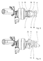
- Fig. 2 shows an electric motor 6 designed as an electric motor drive for the tungsten gear 1 (see. Fig. 1 ) of a trailer hitch 7.
- the Wolfrom transmission 1 also referred to below as transmission 1, has an end face outstanding drive shaft 8, on which a pinion 9, a locking plate 10 with Recesses 10a and - what is not visible - the sun gear 2 (see. Fig. 1 ) are arranged rotationally fixed.
- the electric motor 6 has a motor shaft 6a, which drives the pinion 9.
- a blocking magnet 11 has an extendable latching pin 12, which engages in the recesses 10a of the locking disk 10 and thus blocks the drive shaft 8.
- the mechanical locking by a positive connection between locking pin 12 and locking disc 10 is only when the coupling hook of the trailer hitch 7 in an end position (see. Fig. 8a, 8c ) is located.
- the Wolfrom gear 1 is self-locking, but creeping of the gear may occur under load vibration - hence, the mechanical interlock is provided to maintain the end positions of the coupling hook.
- Fig. 3 shows the output side of the Wolfrom gear 1, the second rotatable ring gear 5 (see. Fig. 1 ) is supported via a bearing 13 against a housing, not shown.
- the transmission axis is designated by a.
- the second ring gear is connected to a driven piece 14, which is designed as a fork piece 14.
- With the fork piece 14 is a cross piece 15 via a pivot pin 16 (see. Figure 5 ), indicated by a dashed line 16, articulated.
- the pivot pin 16 is also referred to as the first pair of pivot pins 16.
- the crosspiece 15 has a second 90 ° relative to the first offset joint pin pair 17.
- the cross piece 15 according to the invention is similar to the cross piece of a universal joint, also called cardan joint.
- the crosspiece 15 has at its output-side end a polygon 18 and a fastening nut 19.
- the polygon 18 (polygon) is used for the positive reception of the coupling hook, not shown here, which will be explained in more detail below. Due to the pivot connection between crosspiece 15 and fork 14, the torque output from the second ring gear is transmitted to the polygon 18.
- Fig. 4 shows the output side of the Wolfrom gear 1 - as in Fig. 3 shown - but in addition to a bearing ring 20 which is arranged obliquely to the transmission axis a and connected via the second pair of pivot pins 17 with the crosspiece 15.
- the bearing ring 20 is rotatably supported in its oblique position in a housing, not shown here, ie it is to a relative to the transmission axis a inclined axis b rotatably, which includes a tilt angle ⁇ with the transmission axis a.
- Fig. 5 shows the transmission 1 with its input and output side and one with the crosspiece 15 by means of the polygon 18 and the mounting nut 19 positively and rotationally fixed coupling hook 21 (shown incomplete).
- the drive shaft 8 with pinion 9 and sun gear 2, the planetary gears 3 and the first and the second ring gear 4, 5 clearly visible.
- the planet gears 3 are mounted on planet pins and rotating planet carrier (without reference number).
- the transmission 1 is received by a transmission housing 22, on which on the one hand, the first ring gear 4 is supported and against which the second ring gear 5 is mounted on the bearing 13.
- the coupling hook 21 has a mounting flange 21 a, which - as mentioned above - is firmly connected to the front end 15 a of the crosspiece 15.
- a Abdeckkapsel 25 or sealing collar attached which slidably rests on the bearing housing 23 and thus during the entire pivoting and tilting movement of the coupling hook 21 causes a seal of the interior. This prevents dirt or dust from contaminating the inside of bearings and joints.
- Fig. 6 shows an overall view of the trailer hitch 7, which is releasably secured by means of a support member 30 to a vehicle-side frame 31.
- Clutch hook 21 is on its mounting flange 21 a to the trailer hitch 7 - as in Fig. 5 shown in more detail - attached and has at the other end to a ball head 21 b, which can be coupled with a (not shown) coupling counterpart.
- Fig. 7 shows the trailer hitch 7 with a conical mounting pin 32, which preferably integrally with the gear housing 22 (see. Fig. 5 ) is formed and can be secured by means of a fastening nut 33 and a disc 34 on the support member 30.
- a fastening nut 33 and a disc 34 on the support member 30.
- Fig. 8a, Fig. 8b and Fig. 8c show the movement during pivoting of the coupling hook 21 from his in Fig. 8a shown operating position in his in Fig. 8c shown rest position.
- the pivot axis a corresponds to the transmission axis a, as in FIG. 3 and FIG. 4 is shown.
- the coupling hook 21 is pivoted from the operating position by 90 °, it is superimposed on a tilting movement, wherein the maximum tilt angle is denoted by ⁇ and can be about 18 °.
- the maximum tilt angle ⁇ is in the middle position according to Fig. 8b reached.
- the coupling hook 21 continues in the direction of rest according to Fig. 8c pivoted, the tilt angle ⁇ is reduced to zero; the coupling hook 21 is in the rest position by 180 ° relative to the operating position according to Fig. 8a pivoted.
- Fig. 9a, Fig. 9b and Fig. 9c show the pivoting process with superimposed tilting movement in reverse order, ie from the rest position according to Fig. 9a in the operating position according to Fig. 9c , Again, the maximum tilt angle ⁇ after pivoting by 90 ° in the middle position according to Fig. 9b reached.
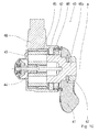
- Fig. 10 shows a second embodiment of the invention, a trailer hitch 40 with a pivotable about the transmission axis a coupling hook 41 (shown incomplete).
- a Wolfrom gear 43 is received, which corresponds to the Wolfrom gear 1 of the first embodiment.
- the drive is also electromotive (not shown) and via the sun gear 44; the output is via the second movable ring gear 45.
- An adapter piece 46 is coaxial with the transmission axis a rotatably disposed in the housing 42 and fixedly connected to the second ring gear 45.
- the adapter piece 46 has a pin 46a on which by means of a fastening nut 47 of the coupling hook 41 is rotatably attached.
- a rotary joint with cross piece is missing - thus eliminating a superimposed tilting movement.
- the coupling hook 41 thus performs only a pure pivoting movement about the transmission axis a.
- the use of the Wolfrom gear 43 is also advantageous in this embodiment as in the first embodiment, as this - as already mentioned above - a very high gear ratio and thus a high torque on the adapter piece 46 can be achieved.
- overrun ie when loaded on the coupling hook 41 by a trailer load on self-locking.
- the trailer hitch 40 thus basically does not need a locking device, which, however, is also provided here due to vibration stresses, according to the first embodiment.
- the trailer hitch 40 has - analogous to the first embodiment - a conical mounting pin 48, which allows attachment to the vehicle.
- FIG. 11a, 11b and 11c show the sequence of pivotal movement of the coupling hook 41 of the trailer hitch 40 (second embodiment).
- Fig. 11 a shows the coupling hook 41 in the operating position, the ball head 41 a points upward, the pivot axis, which corresponds to the transmission axis, is denoted by a.
- Fig. 11b shows the coupling hook 41, pivoted 90 ° about the pivot axis a.
- the ball head 41 a is here in its lowest position.
- Fig. 11c shows the coupling hook 41 after a pivoting 180 ° from the operating position to the rest position.
- the ball head 41 a shows down here.
Abstract
Die Erfindung betrifft eine Anhängerkupplung für Kraftfahrzeuge, umfassend einen schwenkbaren Kupplungshaken, einen elektromotorischen Antrieb (6) und ein zwischen Antrieb (6) und Kupplungshaken angeordnetes Planetengetriebe (1). Es wird vorgeschlagen, dass das Planetengetriebe als Wolfrom-Getriebe (1) ausgebildet ist.The invention relates to a trailer hitch for motor vehicles, comprising a pivotable coupling hook, an electromotive drive (6) and an arranged between the drive (6) and coupling hooks planetary gear (1). It is proposed that the planetary gear is designed as a Wolfrom gear (1).
Description
Die Erfindung betrifft ein Schwenkmodul für eine Anhängerkupplung für Kraftfahrzeuge nach dem Oberbegriff des Patentanspruches 1.The invention relates to a swivel module for a trailer hitch for motor vehicles according to the preamble of
Durch die
Ausgehend von dem vorgenannten Stand der Technik, ist es eine Aufgabe der vorliegenden Erfindung, den Schwenkantrieb zu verbessern, wobei auch eine Schwenkbewegung unter Last möglich sein soll. Darüber hinaus soll der Bewegungsablauf des Kupplungshakens beim Schwenkvorgang besser an die räumlichen Gegebenheiten am Kraftfahrzeug anpassbar sein.Based on the aforementioned prior art, it is an object of the present invention to improve the pivot drive, wherein a pivotal movement under load should be possible. In addition, the movement of the coupling hook should be better adapted to the spatial conditions on the motor vehicle during the pivoting process.
Die Aufgabe der Erfindung wird durch die Merkmale des Patentanspruches 1 gelöst. Vorteilhafte Ausgestaltungen ergeben sich aus den Unteransprüchen.The object of the invention is solved by the features of
Erfindungsgemäß ist vorgesehen, dass das Planetengetriebe zwischen elektromotorischem Antrieb und Abtrieb für einen Kupplungshaken als Wolfrom-Getriebe ausgebildet ist. Ein Wolfrom-Getriebe oder ein Wolfrom-Satz ist aus dem Stand der Technik, insbesondere der einschlägigen Fachliteratur als Wolfromsches Umlaufrädergetriebe bekannt und wird auch als reduziertes Planetengetriebe bezeichnet. Mit dem Wolfrom-Getriebe sind einerseits sehr hohe Übersetzungen, d. h. vom Antrieb in Richtung Abtrieb ins Langsame möglich, andererseits ist das Wolfrom-Getriebe im Schubbetrieb selbsthemmend und wirkt somit als Rücklaufsperre. Im Fall der Anhängerkupplung ergibt sich der Vorteil, dass der Kupplungshaken, insbesondere dessen Kugelkopf bei der Schwenkbewegung durch eine Anhängerlast belastbar ist, ohne dass eine Umkehr der Antriebsrichtung auftritt. Damit wird das Ankoppeln eines Anhängers vorteilhaft unterstützt und erleichtert.According to the invention it is provided that the planetary gear between electromotive drive and output for a coupling hook is designed as a Wolfrom gear. A Wolfrom gear or Wolfrom set is known from the prior art, in particular the relevant literature as Wolfromsches Umlaufrädergetriebe and is also referred to as a reduced planetary gear. With the Wolfrom gearbox on the one hand very high translations, d. H. On the other hand, the Wolfrom gearbox is self-locking in overrun mode and thus acts as a backstop. In the case of the trailer hitch, there is the advantage that the coupling hook, in particular its ball head, can be loaded by a trailer load during the pivoting movement without a reversal of the drive direction occurring. Thus, the coupling of a trailer is advantageously supported and facilitated.
Nach einer bevorzugten Ausführungsform ist das Wolfrom-Getriebe in einem Gehäuse aufgenommen und umfasst ein antreibbares Sonnenrad, Planetenräder, ein erstes festgehaltenes Hohlrad sowie ein zweites bewegliches Hohlrad, welches das Abtriebsglied bildet. Damit ist ein kompakter Antrieb mit einer sehr hohen Übersetzung ins Langsame vom Sonnenrad auf das bewegliche Hohlrad möglich.According to a preferred embodiment, the Wolfrom gear is accommodated in a housing and comprises a drivable sun gear, planet gears, a first fixed ring gear and a second movable ring gear, which forms the output member. Thus, a compact drive with a very high gear ratio is possible from the sun gear to the movable ring gear.
Nach einer weiteren bevorzugten Ausführungsform ist das Abtriebsglied bzw. das bewegliche Hohlrad über mindestens ein Zwischenglied mit dem schwenkbaren Kupplungshaken verbunden. Die Ausbildung des Zwischengliedes beinhaltet mindestens zwei Varianten für die Darstellung des Schwenkvorganges.According to a further preferred embodiment, the output member or the movable ring gear is connected via at least one intermediate member with the pivotable coupling hook. The formation of the intermediate member includes at least two variants for the representation of the pivoting process.
Nach einer weiteren bevorzugten Ausführungsform (erste Variante) ist das mindestens eine Zwischenglied als Adapterstück ausgebildet, welches koaxial zur Getriebeachse angeordnet und drehbar im Gehäuse gelagert ist. Nach dieser Variante kann das Abtriebsglied des Wolfrom-Satzes auf einfache Weise mit dem Kupplungshaken verbunden und eine Schwenkbewegung des Kupplungshakens bewirkt werden.According to a further preferred embodiment (first variant), the at least one intermediate member is formed as an adapter piece which is arranged coaxially to the transmission axis and rotatably mounted in the housing. According to this variant, the output member of the Wolfrom set can be easily connected to the coupling hook and pivotal movement of the coupling hook can be effected.
Nach einer weiteren bevorzugten Ausführungsform (zweite Variante) umfasst das Zwischenglied ein koaxial zur Getriebeachse drehbar angeordnetes Antriebsstück und ein schwenk- und kippbar ausgebildetes Abtriebsstück, wobei das Abtriebsstück über ein Drehgelenk mit dem Antriebsstück verbunden ist. Durch das Drehgelenk ist es möglich, dem Abtriebsstück und damit auch dem Kupplungshaken - zusätzlich zu der Schwenkbewegung - eine Kippbewegung zu überlagern.According to a further preferred embodiment (second variant), the intermediate member comprises a coaxially to the transmission axis rotatably arranged drive piece and a pivotally and tiltably formed output piece, wherein the output piece is connected via a rotary joint with the drive piece. Due to the swivel joint, it is possible to superimpose a tilting movement on the driven piece and thus also on the coupling hook, in addition to the pivoting movement.
Nach einer weiteren bevorzugten Ausführungsform umfasst das Drehgelenk ein abtriebsseitiges Kreuzstück, welches vier jeweils um 90° versetzt gegeneinander angeordnete Gelenkzapfen bzw. zwei Gelenkzapfenpaare aufweist, und ein antriebsseitiges Gabelstück, in welches zwei auf einer gemeinsamen Längsachse angeordnete Gelenkzapfen eingreifen. Das erfindungsgemäße Kreuzstück entspricht dabei dem Kreuzstück eines an sich bekanten Kreuzgelenks, auch Kardangelenk genannt, und das Gabelstück entspricht einer der Gelenkgabeln eines Kardangelenks. Damit ist die Längsachse des Abtriebs- oder Kreuzstückes gegenüber der Längsachse des Antriebs- oder Gabelstückes kippbar.According to a further preferred embodiment, the rotary joint comprises a driven-side cross piece, which has four each offset by 90 ° against each other arranged pivot pin or two pairs of pivot pins, and a drive-side fork piece, in which two arranged on a common longitudinal axis pivot pin engage. The cross piece according to the invention corresponds to the cross piece of a per se bekanten universal joint, also called universal joint, and the fork corresponds to one of the joint forks of a universal joint. Thus, the longitudinal axis of the output or cross piece with respect to the longitudinal axis of the drive or fork piece is tilted.
Nach einer weiteren bevorzugten Ausführungsform greift das zweite Paar von Gelenkzapfen mit gemeinsamer Längsachse in einen Lagerring ein, dessen Längsund Drehachse schräg zur Getriebeachse angeordnet ist. Der Lagerring entspricht somit der zweiten Gelenkgabel eines Kardangelenks, bildet jedoch kein Abtriebsglied, vielmehr zwingt er die drehbar mit ihm verbundenen Gelenkzapfen auf eine Umlaufebene, welche schräg zur Getriebeachse, d. h. in einem definierten Winkel, dem so genannten Kippwinkel angeordnet ist. Damit wird dem Abtriebs- bzw. Kreuzstück während der Schwenkbewegung zusätzlich eine Kippbewegung aufgeprägt.According to a further preferred embodiment, the second pair of pivot pins engages with a common longitudinal axis in a bearing ring, whose longitudinal and rotational axis is arranged obliquely to the transmission axis. The bearing ring thus corresponds to the second yoke of a universal joint, but does not form a driven member, but rather forces the rotatably connected thereto pivot pin on a revolving plane, which obliquely to the transmission axis, d. H. in a defined angle, the so-called tilt angle is arranged. This is the output or cross piece during the pivoting movement additionally imposed a tilting movement.
Nach einer weiteren bevorzugten Ausführungsform ist der Lagerring um seine Längsachse drehbar im Gehäuse gelagert und in seiner schrägen Position abgestützt. Damit werden die aus der überlagerten Kippbewegung resultierenden Reaktionskräfte vom Gehäuse aufgenommen.According to a further preferred embodiment, the bearing ring is rotatably mounted about its longitudinal axis in the housing and supported in its oblique position. Thus, the resulting from the superimposed tilting reaction forces are absorbed by the housing.
Nach einer weiteren bevorzugten Ausführungsform ist das Abtriebs- bzw. Kreuzstück formschlüssig mit dem Abtrieb für den Kupplungshaken verbunden. Damit wird der Vorteil einer sicheren und spielfreien Verbindung zwischen dem Drehgelenk und dem Abtrieb erreicht.According to a further preferred embodiment, the output or cross piece is positively connected to the output for the coupling hook. Thus, the advantage of a secure and play-free connection between the swivel and the output is achieved.
Nach einer weiteren bevorzugten Ausführungsform weist der Abtrieb für den Kupplungshaken einen Befestigungsflansch auf, welcher mit dem Kreuzstück lösbar verbunden ist. Über den Befestigungsflansch werden die am Abtrieb eingeleiteten Kräfte (Anhängerlast) über das Drehgelenk in das Gehäuse eingeleitet, wenn ein Kupplungshaken am Abtrieb befestigt ist.According to a further preferred embodiment, the output for the coupling hook on a mounting flange, which is releasably connected to the crosspiece. About the mounting flange introduced at the output forces (trailer load) are introduced via the rotary joint in the housing when a coupling hook is attached to the output.
Nach einer weiteren bevorzugten Ausführungsform ist der Befestigungsflansch über eine Abdeckkapsel gegenüber dem Gehäuse abgedichtet, d. h. die Abdeckkapsel überbrückt die Relativbewegung zwischen schwenk- und kippbarem Flansch und ortsfestem Gehäuse und schützt somit das Drehgelenk vor Staub und Schmutz von außen.According to a further preferred embodiment, the mounting flange is sealed by a cover capsule relative to the housing, d. H. The capsule bridges the relative movement between pivoting and tilting flange and stationary housing and thus protects the swivel joint from dust and dirt from the outside.
Nach einer weiteren bevorzugten Ausführungsform ist am Gehäuse ein konisch ausgebildeter Befestigungszapfen angeordnet, vorzugsweise angegossen. Über den Befestigungszapfen kann das Getriebe mit Abtrieb für den Kupplungshaken und elektromotorischem Antrieb am Fahrzeug befestigt werden; über den Befestigungszapfen wird die Anhängerlast in die Fahrzeugstruktur eingeleitet.According to a further preferred embodiment, a conically formed fastening pin is arranged, preferably cast, on the housing. About the mounting pin gearbox can be attached to the vehicle with output for the coupling hook and electric motor drive; About the mounting pin, the trailer load is introduced into the vehicle structure.
Nach einer weiteren bevorzugten Ausführungsform ist das Wolfrom-Getriebe über eine Antriebswelle antreibbar, auf welcher das Sonnenrad, ein Ritzel sowie eine Rastscheibe drehfest angeordnet sind. Das Ritzel ist Teil einer Übersetzungsstufe zwischen elektromotorischem Antrieb und Getriebeeingang, während die Rastscheibe Teil eines Verriegelungsmechanismus ist.According to a further preferred embodiment, the Wolfrom transmission is drivable via a drive shaft on which the sun gear, a pinion and a locking disk are arranged rotationally fixed. The pinion is part of a translation stage between the electromotive drive and transmission input, while the locking disc is part of a locking mechanism.
Nach einer weiteren bevorzugten Ausführungsform ist die Rastscheibe über einen vorzugsweise elektromagnetisch betätigbaren Rastbolzen blockierbar. Damit ist es möglich, die Antriebsseite des Wolfrom-Getriebes mechanisch zu verriegeln, was wegen der Selbsthemmung grundsätzlich zwar nicht notwendig, jedoch bei einer dynamischen Schwingungsbeanspruchung des Abtriebs durch den Kupplungshaken vorteilhaft ist.According to a further preferred embodiment, the locking disk can be blocked via a preferably electromagnetically actuated locking pin. This makes it possible to mechanically lock the drive side of the Wolfrom transmission, which is basically not necessary because of the self-locking, but is advantageous in a dynamic vibration stress of the output by the coupling hook.
Bevorzugt wird das Schwenkmodul in Verbindung mit einem an dem Abtrieb form-, kraft- oder auch stoffschlüssig befestigten Kupplungshaken als Anhängerkupplung verwendet. Das Schwenkmodul kann einzeln oder zusammen mit dem Kupplungshaken vorgefertigt werden. Es kann vorgefertigt mit einem Anhängerquerträger verbunden werden, welches an einem Kraftfahrzeug festgelegt ist. Auch kann der Anhängerquerträger mit dem Schwenkmodul und dem Kupplungshaken zur Montage an ein Kraftfahrzeug vorfertigt sein. Das Schwenkmodul kann direkt oder mittels eines Verbinders an dem Anhängerquerträger festgelegt sein. Der Anhängerquerträger ist über an diesem befestigten Längsträgern oder dergleichen an der Karosserie des Kraftfahrzeugs befestigt, z.B. verschraubt.Preferably, the swivel module is used as a trailer hitch in conjunction with a form-fitting, force-fitting or cohesively mounted coupling hook. The swivel module can be prefabricated individually or together with the coupling hook. It can be prefabricated connected to a trailer crossmember, which is fixed to a motor vehicle. Also, the trailer cross member may be prefabricated with the swivel module and the coupling hook for mounting to a motor vehicle. The swivel module can be fixed directly or by means of a connector to the trailer cross member. The trailer cross member is fastened to the body of the motor vehicle by means of longitudinal members or the like fastened thereto, e.g. screwed.
Das Schwenkmodul kann des Weiteren elektrisch per Taster oder Schalter oder auch drahtlos bedienbar ausgestaltet sein. Zur Bedienung des Schwenkvorgangs ist des Weiteren eine Steuerung vorgesehen, die den Schwenkvorgang überwacht, eine Fehlbedienung ausschließt und zudem sicherstellt, dass bei Hindernissen, insbesondere bei Gliedmaßen, es zu keiner Einklemmsituation kommen kann. Eine Überlastung des Schwenkmoduls oder seines Antriebs wird so ebenfalls wirkungsvoll unterbunden.Furthermore, the swivel module can be configured to be electrically operated by means of a push-button or switch or else wirelessly. Furthermore, a control is provided for operating the pivoting process, which monitors the pivoting operation, precludes incorrect operation and, in addition, ensures that in the event of obstacles, in particular limbs, no pinching situation can occur. An overload of the swivel module or its drive is also effectively prevented.
Es versteht sich, dass die vorstehend genannten Merkmale der Erfindung nicht nur in der jeweils angegebenen Kombination, sondern auch in anderen Kombinationen oder in Alleinstellung verwendbar sind, ohne den Rahmen der Erfindung zu verlassen. Ebenso liegt es im Rahmen der Erfindung, eine mechanische Umkehr der Funktionen der einzelnen mechanischen Elemente der Erfindung zu bewirken.It is understood that the abovementioned features of the invention can be used not only in the particular combination specified, but also in other combinations or in isolation, without departing from the scope of the invention. It is also within the scope of the invention to effect a mechanical reversal of the functions of the individual mechanical elements of the invention.
Ausführungsbeispiele der Erfindung sind in der Zeichnung dargestellt und werden im Folgenden näher beschrieben, wobei sich aus der Beschreibung und/oder der Zeichnung weitere Merkmale und/oder Vorteile ergeben können. Es zeigen:
-
Fig. 1 ein Wolfrom-Getriebe in schematischer Darstellung, -
Fig. 2 eine erfindungsgemäße Anhängerkupplung mit elektromotorischem Antrieb, -
Fig. 3 die Anhängerkupplung mit einer Drehgelenkverbindung, -
Fig. 4 die Anhängerkupplung mit Drehgelenk und Lagerring, -
Fig. 5 eine Schnittdarstellung des Wolfrom-Getriebes und der Drehgelenkverbindung, -
Fig. 6 eine Gesamtansicht der Anhängerkupplung mit Kupplungshaken und ihre Befestigung an einem Fahrzeugrahmen, -
Fig. 7 die Anhängerkupplung mit einem Befestigungszapfen, -
Fig. 8a, 8b, 8c den Bewegungsablauf des Kupplungshakens aus der Betriebslage in die Ruhelage, -
Fig. 9a, 9b, 9c den Bewegungsablauf des Kupplungshakens in umgekehrter Reihenfolge: aus der Ruhelage in die Betriebslage, -
Fig. 10 ein zweites Ausführungsbeispiel der Erfindung ohne Drehgelenkverbindung und -
Fig. 11a, 11b, 11c die Schwenkbewegung des Kupplungshakens der Anhängerkupplung gemäßFig. 10 von der Betriebslage in die Ruhelage.
-
Fig. 1 a Wolfrom transmission in a schematic representation, -
Fig. 2 an inventive trailer hitch with electric motor drive, -
Fig. 3 the trailer hitch with a swivel connection, -
Fig. 4 the trailer hitch with swivel joint and bearing ring, -
Fig. 5 a sectional view of the Wolfrom transmission and the pivot connection, -
Fig. 6 an overall view of the trailer hitch with coupling hooks and their attachment to a vehicle frame, -
Fig. 7 the trailer hitch with a mounting pin, -
Fig. 8a, 8b, 8c the movement of the coupling hook from the operating position to the rest position, -
Fig. 9a, 9b, 9c the movement of the coupling hook in reverse order: from the rest position to the operating position, -
Fig. 10 A second embodiment of the invention without pivot connection and -
Fig. 11a, 11b, 11c the pivoting movement of the coupling hook of the trailer hitch according toFig. 10 from the operating position to the rest position.
- 11
- Wolfrom-GetriebeWolfrom gear system
- 22
- Sonnenradsun
- 33
- Planetenradplanet
- 44
- erstes Hohlrad (fest)first ring gear (fixed)
- 55
- zweites Hohlrad (drehbar)second ring gear (rotatable)
- 66
- Elektromotorelectric motor
- 6a6a
- Motorwellemotor shaft
- 77
- Anhängerkupplungtrailer hitch
- 88th
- Antriebswelledrive shaft
- 99
- Ritzelpinion
- 1010
- Rastscheibelocking disc
- 10a10a
- Ausnehmungrecess
- 1111
- Sperrmagnetblocking coil
- 1212
- RastbolzenIndexing plungers
- 1313
- Lager für HohlradBearing for ring gear
- 1414
- Gabelstückforked piece
- 1515
- Kreuzstückcrosspiece
- 15a15a
- Stirnendefront end
- 1616
- erstes Gelenkzapfenpaarfirst pair of pivot pins
- 1717
- zweites Gelenkzapfenpaarsecond pair of pivot pins
- 1818
- Abtrieb, Vielkant (Polygon)Downforce, polygon (Polygon)
- 1919
- Befestigungsmutterfixing nut
- 2020
- Lagerringbearing ring
- 2121
- Kupplungshakencoupling hook
- 21a21a
- Befestigungsflanschmounting flange
- 21b21b
- Kugelkopfball head
- 2222
- Getriebegehäusegearbox
- 2323
- Lagergehäusebearing housing
- 2424
- Schräglagerangular contact bearings
- 2525
- Abdeckkapselcover capsule
- 3030
- Trägerelementsupport element
- 3131
- Rahmenframe
- 3232
- Befestigungszapfenfastening pins
- 3333
- Befestigungsmutterfixing nut
- 3434
- Scheibedisc
- 3535
- Absatzparagraph
- 4040
- Anhängerkupplungtrailer hitch
- 4141
- Kupplungshakencoupling hook
- 41a41a
- Kugelkopfball head
- 4242
- Gehäusecasing
- 4343
- Wolfrom-GetriebeWolfrom gear system
- 4444
- Sonnenradsun
- 4545
- zweites Hohlradsecond ring gear
- 4646
- Adapterstückadapter piece
- 46a46a
- Zapfenspigot
- 4747
- Befestigungsmutterfixing nut
- 4848
- Befestigungszapfenfastening pins
- aa
- GetriebeachseDrive shaft
- bb
- Drehachse (Lagerring)Rotation axis (bearing ring)
- αα
- Kippwinkeltilt angle
Claims (15)
Applications Claiming Priority (1)
| Application Number | Priority Date | Filing Date | Title |
|---|---|---|---|
| DE102013220024.2A DE102013220024A1 (en) | 2013-10-02 | 2013-10-02 | Towbar for motor vehicles |
Publications (1)
| Publication Number | Publication Date |
|---|---|
| EP2857233A1 true EP2857233A1 (en) | 2015-04-08 |
Family
ID=51383618
Family Applications (1)
| Application Number | Title | Priority Date | Filing Date |
|---|---|---|---|
| EP20140181703 Withdrawn EP2857233A1 (en) | 2013-10-02 | 2014-08-21 | Towbar for motor vehicles |
Country Status (2)
| Country | Link |
|---|---|
| EP (1) | EP2857233A1 (en) |
| DE (1) | DE102013220024A1 (en) |
Cited By (2)
| Publication number | Priority date | Publication date | Assignee | Title |
|---|---|---|---|---|
| CN113524993A (en) * | 2021-05-20 | 2021-10-22 | 浙江致优汽车科技有限公司 | Self-locking electric trailer hook device |
| EP4194232A1 (en) * | 2021-12-10 | 2023-06-14 | Brink Towing Systems B.V. | Towing hook arrangement |
Families Citing this family (1)
| Publication number | Priority date | Publication date | Assignee | Title |
|---|---|---|---|---|
| DE102018124549A1 (en) * | 2018-10-04 | 2020-04-09 | Westfalia-Automotive Gmbh | Trailer coupling |
Citations (5)
| Publication number | Priority date | Publication date | Assignee | Title |
|---|---|---|---|---|
| WO1997010111A1 (en) * | 1995-09-13 | 1997-03-20 | Cartron Fahrzeugteile Gmbh | Motor vehicle trailer coupling |
| EP1504928A1 (en) | 2003-08-08 | 2005-02-09 | Westfalia Automotive GmbH & Co. KG | Trailer hitch |
| DE102006037675A1 (en) * | 2006-08-11 | 2008-02-21 | Paragon Ag | Trailer coupling for vehicle, has mechanical actuator, by which knee-joint bar, which has coupling ball at its free end, is controlled by pivoting movement from rest position into operating position |
| DE102009045290A1 (en) * | 2009-10-02 | 2011-04-07 | Zf Friedrichshafen Ag | Tumbling ball joint for pivotable trailer coupling, has joint ball with front side formed as toothed wheel plate, which meshes with bevel gears that are rotatably supported at housing and rotatable by drive |
| DE102009049271A1 (en) * | 2009-10-06 | 2011-04-07 | Imo Holding Gmbh | Seamless epicyclic gearbox |
Family Cites Families (6)
| Publication number | Priority date | Publication date | Assignee | Title |
|---|---|---|---|---|
| DE10350040A1 (en) * | 2003-10-27 | 2005-05-25 | Robert Bosch Gmbh | Gear drive unit |
| DE102005056217A1 (en) * | 2005-11-25 | 2007-06-06 | Jaeger Cartronix Gmbh | Drive unit for a trailer hitch |
| DE102006033031B4 (en) * | 2006-07-14 | 2008-07-24 | Paragon Ag | Towbar for motor vehicles |
| DE102008018739A1 (en) * | 2008-04-14 | 2009-10-15 | Trw Automotive Gmbh | Vehicle-side coupling assembly of a trailer hitch |
| DE102009015916A1 (en) * | 2009-03-25 | 2010-10-07 | Scambia Industrial Developments Aktiengesellschaft | Towing |
| DE102011014882A1 (en) * | 2011-03-23 | 2012-09-27 | Westfalia-Automotive Gmbh | Towing |
-
2013
- 2013-10-02 DE DE102013220024.2A patent/DE102013220024A1/en not_active Ceased
-
2014
- 2014-08-21 EP EP20140181703 patent/EP2857233A1/en not_active Withdrawn
Patent Citations (5)
| Publication number | Priority date | Publication date | Assignee | Title |
|---|---|---|---|---|
| WO1997010111A1 (en) * | 1995-09-13 | 1997-03-20 | Cartron Fahrzeugteile Gmbh | Motor vehicle trailer coupling |
| EP1504928A1 (en) | 2003-08-08 | 2005-02-09 | Westfalia Automotive GmbH & Co. KG | Trailer hitch |
| DE102006037675A1 (en) * | 2006-08-11 | 2008-02-21 | Paragon Ag | Trailer coupling for vehicle, has mechanical actuator, by which knee-joint bar, which has coupling ball at its free end, is controlled by pivoting movement from rest position into operating position |
| DE102009045290A1 (en) * | 2009-10-02 | 2011-04-07 | Zf Friedrichshafen Ag | Tumbling ball joint for pivotable trailer coupling, has joint ball with front side formed as toothed wheel plate, which meshes with bevel gears that are rotatably supported at housing and rotatable by drive |
| DE102009049271A1 (en) * | 2009-10-06 | 2011-04-07 | Imo Holding Gmbh | Seamless epicyclic gearbox |
Cited By (2)
| Publication number | Priority date | Publication date | Assignee | Title |
|---|---|---|---|---|
| CN113524993A (en) * | 2021-05-20 | 2021-10-22 | 浙江致优汽车科技有限公司 | Self-locking electric trailer hook device |
| EP4194232A1 (en) * | 2021-12-10 | 2023-06-14 | Brink Towing Systems B.V. | Towing hook arrangement |
Also Published As
| Publication number | Publication date |
|---|---|
| DE102013220024A1 (en) | 2015-04-02 |
Similar Documents
| Publication | Publication Date | Title |
|---|---|---|
| EP3116735B1 (en) | Drive axle assembly | |
| WO2015185036A1 (en) | Planetary gearbox | |
| DE102011115227A1 (en) | Dual clutch assembly | |
| DE102011050440B3 (en) | Automatically switching clutch for a vehicle exterior mirror adjustment | |
| DE10157085A1 (en) | Stabilizer arrangement for a motor vehicle | |
| DE2734568A1 (en) | ARTICULATED FITTING FOR SEATS WITH ADJUSTABLE BACKREST, IN PARTICULAR MOTOR VEHICLE SEATS | |
| EP2857233A1 (en) | Towbar for motor vehicles | |
| DE60118263T2 (en) | Drive shaft made of aluminum with constant velocity joint | |
| EP0228617A2 (en) | Driving device for optionally driving the wheels of the supporting shaft of a motor vehicle | |
| EP2036421B1 (en) | Device for coupling a jointed shaft with a p.t.o. shaft of a tractor | |
| EP0949106B1 (en) | Gearbox for a vehicle with laterally offset engine | |
| EP1608540A1 (en) | Height-adjustable support for semitrailers or the like | |
| DE2110434C3 (en) | Gear change transmission in group design for motor vehicles with a central tubular frame and in particular with a multi-axis drive | |
| DE3138208A1 (en) | Power transmission device for motor vehicles, especially tractors | |
| DE1555953C3 (en) | Drive device for motor vehicles to be shifted into two-wheel or four-wheel drive, in particular combine harvesters | |
| DE4206085A1 (en) | HYDROMECHANICAL DRIVE UNIT FOR THE HYDROSTATIC DRIVE DRIVE OF A VEHICLE | |
| WO2009027410A1 (en) | Driving device | |
| DE3920934A1 (en) | Trailer with two axles - has elements to drive road wheels to facilitate manoeuvring in restricted space | |
| EP1101964A1 (en) | Overload coupling | |
| EP3706531B1 (en) | Vehicle-side and accessory-side power take-off shaft connecting device and power take-off shaft connecting unit comprising the two power take-off shaft connecting devices | |
| DE102016216790B4 (en) | Planetary gears, namely spur gear differentials or a reduction stage therefor | |
| DE102011081340B3 (en) | A semi-trailer supporting apparatus comprising a multi-spindle spindle mechanism and semi-trailer having such a supporting device and a spindle for use in a supporting device | |
| DE3109622A1 (en) | POWER STEERING DEVICE FOR MOTOR VEHICLES | |
| WO2019057397A1 (en) | Housing unit and axle assembly | |
| DE102012011069A1 (en) | Actuation system for a trailer hitch of a motor vehicle |
Legal Events
| Date | Code | Title | Description |
|---|---|---|---|
| PUAI | Public reference made under article 153(3) epc to a published international application that has entered the european phase |
Free format text: ORIGINAL CODE: 0009012 |
|
| 17P | Request for examination filed |
Effective date: 20140821 |
|
| AK | Designated contracting states |
Kind code of ref document: A1 Designated state(s): AL AT BE BG CH CY CZ DE DK EE ES FI FR GB GR HR HU IE IS IT LI LT LU LV MC MK MT NL NO PL PT RO RS SE SI SK SM TR |
|
| AX | Request for extension of the european patent |
Extension state: BA ME |
|
| STAA | Information on the status of an ep patent application or granted ep patent |
Free format text: STATUS: THE APPLICATION IS DEEMED TO BE WITHDRAWN |
|
| 18D | Application deemed to be withdrawn |
Effective date: 20151009 |