EP2856915B1 - Faltmechanik mit Hubparallelogramm für eine Faltliege - Google Patents
Faltmechanik mit Hubparallelogramm für eine Faltliege Download PDFInfo
- Publication number
- EP2856915B1 EP2856915B1 EP14187752.2A EP14187752A EP2856915B1 EP 2856915 B1 EP2856915 B1 EP 2856915B1 EP 14187752 A EP14187752 A EP 14187752A EP 2856915 B1 EP2856915 B1 EP 2856915B1
- Authority
- EP
- European Patent Office
- Prior art keywords
- stop
- folding mechanism
- frame
- seat frame
- mechanism according
- Prior art date
- Legal status (The legal status is an assumption and is not a legal conclusion. Google has not performed a legal analysis and makes no representation as to the accuracy of the status listed.)
- Not-in-force
Links
- 230000008878 coupling Effects 0.000 claims description 34
- 238000010168 coupling process Methods 0.000 claims description 34
- 238000005859 coupling reaction Methods 0.000 claims description 34
- 238000013016 damping Methods 0.000 claims description 3
- 229920003023 plastic Polymers 0.000 claims description 2
- 239000004033 plastic Substances 0.000 claims description 2
- 230000000284 resting effect Effects 0.000 claims 3
- 239000000463 material Substances 0.000 claims 1
- 210000004744 fore-foot Anatomy 0.000 description 13
- 210000002683 foot Anatomy 0.000 description 7
- 238000010276 construction Methods 0.000 description 1
- 230000001360 synchronised effect Effects 0.000 description 1
Images
Classifications
-
- A—HUMAN NECESSITIES
- A47—FURNITURE; DOMESTIC ARTICLES OR APPLIANCES; COFFEE MILLS; SPICE MILLS; SUCTION CLEANERS IN GENERAL
- A47C—CHAIRS; SOFAS; BEDS
- A47C17/00—Sofas; Couches; Beds
- A47C17/04—Seating furniture, e.g. sofas, couches, settees, or the like, with movable parts changeable to beds; Chair beds
- A47C17/16—Seating furniture changeable to beds by tilting or pivoting the back-rest
- A47C17/20—Seating furniture changeable to beds by tilting or pivoting the back-rest thereby uncovering one or more auxiliary parts previously hidden
- A47C17/207—Seating furniture changeable to beds by tilting or pivoting the back-rest thereby uncovering one or more auxiliary parts previously hidden with seat cushion consisting of multiple superposed parts, at least one lower hidden part being used to form part of the bed surface
- A47C17/2076—Seating furniture changeable to beds by tilting or pivoting the back-rest thereby uncovering one or more auxiliary parts previously hidden with seat cushion consisting of multiple superposed parts, at least one lower hidden part being used to form part of the bed surface by lifting or tilting
Definitions
- the invention relates to a folding mechanism for a folding lounger with a head frame, back frame and seat frame, which are pivotally connected to each other from a closed sitting position in an open lying position movable and the back and seat frame are folded by means of a lifting device on side base plates with feet pivotally arranged, said in each case a lifting device is arranged on each base plate, and the seat frame lowered in the lying position is additionally held on fore feet.
- folding tables which can be unfolded from a closed sitting position into an open lying position.
- Such folding looms usually each have on both sides of a base frame held kinematic structures of several struts and joints, in addition to the pivoting of the folding lounger when converting from the sitting position to the lying position another movement to unfold the folding lounger when opening in the lying position or another movement require to close when closing in the sitting position. Consequently, the operation of the folding lounger when opening and closing only in several combined movements and thus difficult possible.
- Patent EP 1 903 916 B1 discloses a folding lounger with scissors, which consists of a head, back and foot frame, which are hinged together and folded with a Hub fitting in a base frame can be raised and lowered arranged.
- the Hubbeschlag consists of both sides of the head frame arranged spring-loaded scissors, which are arranged with a first scissor arm on the base frame and a second scissor arm on the head frame.
- the disadvantage is the load transfer in the scissors in a single pivot of the intersecting scissor arms, so that a correspondingly rigid or heavy construction must be considered.
- the arrangement of the scissors on the head frame prevents the head frame in a set up Sitting position is movable.
- a folding lounger according to the preamble of claim 1 is of FR 2 91 457A1 known.
- the invention is therefore based on the object, a folding mechanism for a folding lounger, which is convertible from a closed sitting position in an open lying position, such that the folding lounger can be very easily opened and closed in only one movement, the head frame serves as a backrest ,
- the folding mechanism for a folding lounger has a head frame, back frame and seat frame, which are hinged together so that they are movable from a closed sitting position to an open lying position.
- the back and seat frame is folded by means of a lifting device arranged pivotally on lateral base plates, wherein the base plates are supported with feet on the ground.
- the distance to the floor is 9 cm.
- a lifting device is arranged on each base plate and in the lying position of the lowered seat frame is held in addition to front feet, which are supported on the ground.
- the folding mechanism carries a mattress, for example, with a thickness of 12 cm and a length of 2 m. For this reason, the folding mechanism is designed so that in the sitting position of the folding mechanism between the folded seat and back frame a mattress with 12 cm thickness can be maintained.
- the folding mechanism of the convertible folding lounger very easily opens and closes in only one movement.
- the lifting device as a Hubparallelogramm from a first connecting rod, a first coupling rod, a second coupling rod and a control strut, which are interconnected by four hinge points.
- the first connecting rod has two pivot points and the second coupling rod also has two pivot points, between which the first coupling rod and the control strut are articulated to a Hubparallelogramm for raising and lowering the seat frame.
- the first coupling rod has a length which corresponds to the length of Control strut corresponds, and the distance between the two pivot points on the first connecting rod is equal to the distance between the two hinge points on the second coupling rod.
- the Hubparallelogramm guaranteed high stability of the folding mechanism both in the closed seating position and in the open lying position of the folding lounger.
- first coupling rod and the control strut of Hubparallelogramms are hinged via one hinge point to the base plate.
- a second connecting rod is articulated via a further pivot point to the base plate, wherein the second connecting rod is in turn connected to a handlebar with the head frame.
- the Hubparallelogramm is connected via a common pivot point with the handlebar and the second connecting rod.
- This link has a recess in which a first stop is guided, which in turn is attached to the base plate.
- the handlebar carries the head frame. In this way, the head frame is pivotable together with the seat frame in a single movement of the established sitting position in the lowered lying position and in the opposite direction, only one movement is also necessary.
- the recess of the handlebar has a plurality of support points on which the first stop is supported in the different positions of the folding mechanism.
- the first stop In the lying position, the first stop is supported on a first support point of the recess.
- the first stop In contrast, in the sitting position, the first stop is supported on a second support point of the recess.
- the first stop In an intermediate position of the folding mechanism, the first stop is supported on a third support point of the recess.
- the recess of the handlebar are designed as a circular ring cutout and guided therein first stop as a stop pin with sleeve.
- the first connecting rod of Hubparallelogramms is spring-loaded by a return spring in the direction of the base plate, so that when lowering the seat frame a Damping is exercised on the Hubparallelogramm.
- a tensile force is exerted by the return spring on the Hubparallelogramm when lifting the seat frame.
- a respective holding point is attached to the base plate and to the first connecting rod, on which the two ends of the return spring are held. Particularly advantageous is supported by the return spring, the weight of the seat frame both when lowering and when lifting.
- the forefoot is articulated at a hinge point of the second coupling rod.
- the forefoot has a hinge point to which a third connecting rod is deflected to unfold and fold the forefoot, which in turn is connected to a pivot point of the control strut with the Hubparallelogramm.
- the base plate has a second stop, which is designed as a stop pin with sleeve. On this second stop, the back frame rests in the sitting position of the folding mechanism.
- the forefoot on a third stop which is carried out in the same way as a stop pin with sleeve. On this third stop the seat frame rests in the sitting position of the folding mechanism.
- the first coupling rod on a fourth stop which is designed as a stop plate made of plastic. On this fourth stop the Hubparallelogramm rests in the sitting position of the folding mechanism. Consequently, in the sitting position of the folding mechanism of the head, back and seat frame via the stops coupled together.
- the head frame is attached to the side arms, the back frame on the side first connecting rods and the seat frame to the side second coupling rods, which are arranged on both sides of the frame.
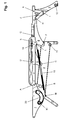
- Fig. 1 shows a preferred embodiment of the folding mechanism with Hubparallelogramm in side view.
- the folding mechanism serves to pivot a folding lounger with a head frame 13, back frame 14 and seat frame 15, on which a mattress is held, very easily from a set sitting position SP into a lowered lying position LP in a single movement.
- the folding mechanism is arranged on both sides of the frame 13, 14, 15.
- the head frame 13 is attached to the side links 1
- the back frame 14 is attached to the side first connecting rods 3
- the seat frame 15 is attached to the side second coupling rods 8 of the folding mechanism.
- Fig. 1 the folding mechanism is shown in the lowered lying position LP without the frames 13, 14, 15.
- the head frame 13, the back frame 14, and the seat frame 15 in the position are horizontal.
- the raised seating position SP of the back 14 and seat frame 15 are folded by means of a lifting device on lateral base plates 2 raised and lowered, with each base plate 2 with a rear and front base 17, 18 is supported on the ground.
- the base plate 2 comprises the second stop 11.
- the lifting device is designed as a Hubparallelogramm consisting of the first connecting rod 3, the first coupling rod 5, the second coupling rod 8 and the control strut 6.
- the first connecting rod 3, two hinge points D and E and the second coupling rod 8 two hinge points G and J, between which each of the first coupling rod 5 and the control strut 6 for raising and lowering the seat frame 15 are hinged.
- the first coupling rod 5 comprises the fourth stop 19.
- first coupling rod 5 via the hinge point C and the control strut 6 via the hinge point F hinged on top of the base plate 2.
- first connecting rod 3 is connected together with the link 1 and the second connecting rod 4 via the common pivot point A.
- second connecting rod 4 is in turn articulated via the hinge point B to the base plate 2.
- the handlebar 1 comprises a recess 20, which is designed as a circular ring cutout.
- a first stop 10 is guided, which is attached to the head plate 2 on the head side.
- the Hubparallelogramm is spring-loaded by the return spring 16 which is fixed between the breakpoint M of the base plate 2 and the breakpoint L of the first connecting rod 3.
- the spring force of the return spring 16 causes a damping when lowering the seat frame 15 to the ground and a tensile force on the Hubparallelogramm when lifting the seat frame 15 from the ground.
- the lowered in the lying position LP seat frame 15 is held on the front feet 9.
- the forefoot 9 is articulated at a hinge point K of the second coupling rod 8 and a third connecting rod 7, which is articulated between the hinge point I on the forefoot 9 and the hinge point H on the control strut 6, causes the unfolding or folding of the forefoot 9 during lowering or raising the seat frame 15.
- the forefoot 9 comprises the third stop 12.
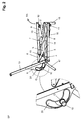
- Fig. 2 shows the folding mechanism with Hubparallelogramm in a closed seating position SP in side view.
- the Hubparallelogramm 3, 5, 6, 8 of the folding mechanism is closed, the back frame 14 and the seat frame 15 are folded and rest by means of the feet 17, 18 on the floor.
- About the stops 10, 11, 12, 19 on the right and left side is a coupling of the folding mechanism.
- the head frame 13 is set up, wherein the head frame 13 is locked by means of the first stop 10 at a certain angle to the second support point O of the recess 20.
- the fourth stopper 19 contacts the second connecting rod 4.
- the back frame 14 rests on the second stopper 11 and the seat frame 15 rests on the third stopper 12.
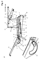
- Fig. 3 shows the folding mechanism with Hubparallelogramm in a half-open intermediate position ZP in side view.
- the seat frame 15 is mounted on the second coupling rod 8 of Hubparallelogramms, which is fixed by the hinge point J on the control strut 6 of Hubparallelogramms.
- a third connecting rod 7 is pivotally mounted by means of the hinge point H, wherein the third connecting rod 7 is in turn pivotally mounted on the forefoot 9 by means of the hinge point I.
- the forefoot 9 is fixed by the hinge point K on the second coupling rod 8 of Hubparallelogramms.
- the control strut 6 of Hubparallelogramms is mounted on the hinge plate F on the base plate 2. Due to the pivoting movement AA, the seat frame 15 rises and no longer touches the third stop 12 on the forefoot 9.
- a further pivot point A is provided on the first connecting rod 3 in order to fix the second connecting rod 4 to the handlebar 1 of the head frame 13.
- Another hinge point B is provided to fix the second connecting rod 4 on the base plate 2.
- the head frame 13 continues to descend by the pulling movement BB and the first stopper 10 leaves its second support point O and slides into the support point P of the recess 20, which is integrated in the handlebar 1.
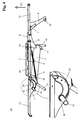
- Fig. 4 shows the folding mechanism with Hubparallelogramm in an open lying position LP in side view.
- the return spring 16 is completely tensioned.
- the first stop 10 slides into the support point N of the recess 20, which is integrated in the handlebar 1.
- the three frames 13, 14, 15 are perfectly in the horizontal position and the folding lounger is very stable.
Landscapes
- Health & Medical Sciences (AREA)
- General Health & Medical Sciences (AREA)
- Nursing (AREA)
- Special Chairs (AREA)
- Mattresses And Other Support Structures For Chairs And Beds (AREA)
Description
- Die Erfindung betrifft eine Faltmechanik für eine Faltliege mit einem Kopfrahmen, Rückenrahmen und Sitzrahmen, die miteinander gelenkig verbunden aus einer geschlossenen Sitzstellung in eine geöffnete Liegestellung bewegbar sind und der Rücken- und Sitzrahmen mittels einer Hubvorrichtung zusammengefaltet auf seitlichen Grundplatten mit Standfüßen schwenkbar angeordnet sind, wobei jeweils eine Hubvorrichtung an jeder Grundplatte angeordnet ist, und der in der Liegestellung abgesenkte Sitzrahmen zusätzlich auf Vorderfüßen gehalten ist.
- Verschiedenste Faltliegen sind bekannt, die aus einer geschlossenen Sitzstellung in eine geöffnete Liegestellung aufgefaltet werden können. Derartige Faltliegen weisen gewöhnlich jeweils beidseitig an einem Grundgestell gehaltene kinematische Strukturen von mehreren Streben und Gelenken auf, die neben dem Schwenken der Faltliege beim Umwandeln aus der Sitzstellung in die Liegestellung eine weitere Bewegung zum Aufklappen der Faltliege beim Öffnen in die Liegestellung bzw. eine weitere Bewegung zum Zuklappen beim Schließen in die Sitzstellung erfordern. Demzufolge ist die Bedienung der Faltliege beim Öffnen und Schließen nur in mehreren kombinierten Bewegungsabläufen und damit erschwert möglich.
- In der
Patentschrift EP 1 903 916 B1 ist eine Faltliege mit Hubschere offenbart, die aus einem Kopf-, Rücken- und Fußrahmen besteht, die miteinander gelenkig verbunden und zusammengefaltet mit einem Hubbeschlag in einem Grundrahmen heb- und absenkbar angeordnet sind. Dabei besteht der Hubbeschlag aus beidseitig an dem Kopfrahmen angeordneten federbelasteten Hubscheren, die mit einem ersten Scherenarm am Grundrahmen und mit einem zweiten Scherenarm am Kopfrahmen angeordnet sind. Nachteilig erfolgt die Lastübertragung bei der Hubschere in einem einzelnen Drehgelenk der sich kreuzenden Scherenarme, so dass eine entsprechend steife bzw. schwere Konstruktion berücksichtigt werden muss. Darüber hinaus verhindert die Anordnung der Hubschere am Kopfrahmen, dass der Kopfrahmen in eine aufgestellte Sitzstellung bewegbar ist. - Eine Faltliege nach dem Oberbegriff des Anspruchs 1 ist von
FR 2 91 457A1 - Der Erfindung liegt daher die Aufgabe zugrunde, eine Faltmechanik für eine Faltliege, die aus einer geschlossenen Sitzstellung in eine geöffnete Liegestellung wandelbar ist, derart auszubilden, dass sich die Faltliege sehr leicht in nur einer Bewegung öffnen und schließen lässt, wobei der Kopfrahmen als Rückenlehne dient.
- Diese Aufgabe wird durch die Merkmale des Anspruchs 1 gelöst.
Ausführungsformen der Erfindung sind in den Unteransprüchen beschrieben. - Die Faltmechanik für eine Faltliege besitzt einen Kopfrahmen, Rückenrahmen und Sitzrahmen, die miteinander gelenkig verbunden sind, so dass sie aus einer geschlossenen Sitzstellung in eine geöffnete Liegestellung bewegbar sind. Dabei ist der Rücken- und Sitzrahmen mit Hilfe einer Hubvorrichtung zusammengefaltet auf seitlichen Grundplatten schwenkbar angeordnet, wobei sich die Grundplatten mit Standfüßen am Boden abstützen. Beispielsweise beträgt der Abstand zum Fußboden 9 cm. Dabei ist jeweils eine Hubvorrichtung an jeder Grundplatte angeordnet und in der Liegestellung ist der abgesenkte Sitzrahmen auf zusätzlich Vorderfüßen gehalten, die sich am Boden abstützen. Die Faltmechanik trägt eine Matratze beispielsweise mit einer Stärke von 12 cm und mit einer Länge von 2 m. Aus diesem Grund ist die Faltmechanik so ausgebildet, dass in der Sitzstellung der Faltmechanik zwischen dem zusammengefalteten Sitz- und Rückenrahmen eine Matratze mit 12 cm Stärke gehalten werden kann.
- Mit den neuen Merkmalen der Erfindung wird erreicht, dass sich die Faltmechanik der wandelbaren Faltliege sehr leicht in nur einer Bewegung öffnet und schließt. Dabei besteht die Hubvorrichtung als ein Hubparallelogramm aus einer ersten Pleuelstange, einer ersten Kupplungsstange, einer zweiten Kupplungsstange und einer Steuerstrebe, die durch vier Gelenkpunkte miteinander verbunden sind. Diesbezüglich weist die erste Pleuelstange zwei Gelenkpunkte und die zweite Kupplungsstange ebenfalls zwei Gelenkpunkte auf, zwischen denen die erste Kupplungsstange und die Steuerstrebe zu einem Hubparallelogramm zum Anheben und Absenken des Sitzrahmens angelenkt sind. Dabei weist die erste Kupplungsstange eine Länge auf, die der Länge der Steuerstrebe entspricht, und der Abstand der beiden Gelenkpunkte auf der ersten Pleuelstange ist gleich groß wie der Abstand der beiden Gelenkpunkte auf der zweiten Kupplungsstange. Vorteilhaft garantiert das Hubparallelogramm eine hohe Stabilität der Faltmechanik sowohl in der geschlossenen Sitzstellung als auch in der geöffneten Liegestellung der Faltliege.
- Außerdem sind die erste Kupplungsstange und die Steuerstrebe des Hubparallelogramms über je einen Gelenkpunkt an die Grundplatte angelenkt. Darüber hinaus ist eine zweite Pleuelstange über einen weiteren Gelenkpunkt an die Grundplatte angelenkt, wobei die zweite Pleuelstange wiederum an einem Lenker mit dem Kopfrahmen verbunden ist. Infolgedessen wird der Kopf- und Rückenrahmen beim Schwenken der Faltmechanik von der Sitzstellung in die Liegestellung und umgekehrt angehoben bzw. abgesenkt.
- Das Hubparallelogramm ist über einen gemeinsamen Gelenkpunkt mit dem Lenker und der zweiten Pleuelstange verbunden. Dieser Lenker weist eine Aussparung auf, in der ein erster Anschlag geführt ist, der wiederum an der Grundplatte befestigt ist. Zudem trägt der Lenker den Kopfrahmen. Auf diese Weise ist der Kopfrahmen zusammen mit dem Sitzrahmen in einer einzigen Bewegung von der aufgestellten Sitzstellung in die abgesenkte Liegestellung schwenkbar und in umgekehrter Richtung ist ebenfalls nur eine Bewegung notwendig.
- Die Aussparung des Lenkers weist mehrere Stützpunkte auf, an denen der erste Anschlag in den unterschiedlichen Stellungen der Faltmechanik gestützt ist. In der Liegestellung stützt sich der erste Anschlag an einem ersten Stützpunkt der Aussparung ab. Dagegen ist in der Sitzstellung der erste Anschlag an einem zweiten Stützpunkt der Aussparung gestützt. Wohingegen in einer Zwischenstellung der Faltmechanik sich der erste Anschlag auf einen dritten Stützpunkt der Aussparung stützt. Hierzu sind die Aussparung des Lenkers als ein Kreisringausschnitt und der darin geführte erste Anschlag als ein Anschlagbolzen mit Hülse ausgeführt.
- Gleichzeitig ist die erste Pleuelstange des Hubparallelogramms von einer Rückstellfeder in Richtung der Grundplatte federbelastet, so dass beim Absenken des Sitzrahmens eine Dämpfung auf das Hubparallelogramm ausgeübt wird. Andererseits wird beim Anheben des Sitzrahmens eine Zugkraft durch die Rückstellfeder auf das Hubparallelogramm ausgeübt. Hierzu ist an der Grundplatte und an der ersten Pleuelstange je ein Haltepunkt angebracht, an denen die beiden Enden der Rückstellfeder gehalten sind. Besonders vorteilhaft wird durch die Rückstellfeder das Gewicht des Sitzrahmens sowohl beim Absenken als auch beim Anheben unterstützt.
- Der Vorderfuß ist an einem Gelenkpunkt der zweiten Kupplungsstange angelenkt. Gleichzeitig weist der Vorderfuß einen Gelenkpunkt auf, an dem eine dritte Pleuelstange zum Ausklappen und Einklappen des Vorderfusses an gelenkt ist, die wiederum an einem Gelenkpunkt der Steuerstrebe mit dem Hubparallelogramm verbunden ist. Somit wird der Vorderfuß in der Liegestellung der Faltmechanik automatisch ausgeklappt und in der Sitzstellung wieder eingeklappt.
- Die Grundplatte weist einen zweiten Anschlag auf, der als ein Anschlagbolzen mit Hülse ausgeführt ist. Auf diesem zweiten Anschlag ruht der Rückenrahmen in der Sitzstellung der Faltmechanik. Außerdem weist der Vorderfuß einen dritten Anschlag auf, der in gleicher Weise als ein Anschlagbolzen mit Hülse ausgeführt ist. Auf diesem dritten Anschlag ruht der Sitzrahmen in der Sitzstellung der Faltmechanik. Zusätzlich weist die erste Kupplungsstange einen vierten Anschlag auf, der als eine Anschlagplatte aus Kunststoff ausgeführt ist. Auf diesem vierten Anschlag ruht das Hubparallelogramm in der Sitzstellung der Faltmechanik. Folglich ist in der Sitzstellung der Faltmechanik der Kopf-, Rücken- und Sitzrahmen über die Anschläge miteinander verkoppelt.
- In einer vorteilhaften Ausführung ist der Kopfrahmen an den seitlichen Lenkern, der Rückenrahmen an den seitlichen ersten Pleuelstangen und der Sitzrahmen an den seitlichen zweiten Kupplungsstangen befestigt, die beidseitig der Rahmen angeordnet sind.
- Die Erfindung ist nachfolgend anhand von bevorzugten Ausführungsbeispielen unter Bezugnahme auf die Abbildungen beispielhaft erläutert. Dabei zeigt schematisch:
-
Fig. 1 eine bevorzugte Ausführungsform einer Faltmechanik mit Hubparallelogramm in Seitenansicht, -
Fig. 2 die Faltmechanik mit Hubparallelogramm in einer geschlossenen Sitzstellung in Seitenansicht, -
Fig. 3 die Faltmechanik mit Hubparallelogramm in einer halb geöffneten Zwischenstellung in Seitenansicht, -
Fig. 4 die Faltmechanik mit Hubparallelogramm in einer geöffneten Liegestellung in Seitenansicht. -
Fig. 1 zeigt eine bevorzugte Ausführungsform der Faltmechanik mit Hubparallelogramm in Seitenansicht. - Die Faltmechanik dient dazu, eine Faltliege mit einem Kopfrahmen 13, Rückenrahmen 14 und Sitzrahmen 15, auf der eine Matratze gehalten ist, sehr leicht von einer aufgestellten Sitzstellung SP in eine abgesenkte Liegestellung LP in einer einzigen Bewegung zu schwenken. Dabei ist die Faltmechanik zu beiden Seiten der Rahmen 13, 14, 15 angeordnet. Der Kopfrahmen 13 ist an den seitlichen Lenkern 1, der Rückenrahmen 14 ist an den seitlichen ersten Pleuelstangen 3 und der Sitzrahmen 15 ist an den seitlichen zweiten Kupplungsstangen 8 der Faltmechanik befestigt.
- In
Fig. 1 ist die Faltmechanik in der abgesenkten Liegestellung LP ohne die Rahmen 13, 14, 15 gezeigt. Dabei sind der Kopfrahmen 13, der Rückenrahmen 14, und der Sitzrahmen 15 in der Lage waagerecht. In der aufgestellten Sitzstellung SP sind der Rücken- 14 und Sitzrahmen 15 mittels einer Hubvorrichtung zusammengefaltet auf seitlichen Grundplatten 2 heb- und absenkbar angeordnet, wobei sich jede Grundplatte 2 mit einem hinteren und vorderen Standfuß 17, 18 am Boden abstützt. Untenseitig umfasst die Grundplatte 2 den zweiten Anschlag 11. - Die Hubvorrichtung ist als ein Hubparallelogramm ausgeführt, das aus der ersten Pleuelstange 3, der ersten Kupplungsstange 5, der zweiten Kupplungsstange 8 und der Steuerstrebe 6 besteht. Dabei weisen die erste Pleuelstange 3 zwei Gelenkpunkte D und E und die zweite Kupplungsstange 8 zwei Gelenkpunkte G und J auf, zwischen denen jeweils die erste Kupplungsstange 5 und die Steuerstrebe 6 zum Anheben und Absenken des Sitzrahmens 15 angelenkt sind. Überdies umfasst die erste Kupplungsstange 5 den vierten Anschlag 19.
- Darüber hinaus sind die erste Kupplungsstange 5 über den Gelenkpunkt C und die Steuerstrebe 6 über den Gelenkpunkt F obenseitig an die Grundplatte 2 angelenkt. Kopfseitig ist die erste Pleuelstange 3 zusammen mit dem Lenker 1 und der zweiten Pleuelstange 4 über den gemeinsamen Gelenkpunkt A verbunden. Dabei ist die zweite Pleuelstange 4 wiederum über den Gelenkpunkt B an die Grundplatte 2 angelenkt. Resultierend daraus werden der Kopf- 13 und der Rückenrahmen 14 beim Schwenken der Faltmechanik in die Liegestellung LP angehoben und beim Schwenken in die Sitzstellung SP abgesenkt.
- Der Lenker 1 umfasst eine Aussparung 20, die als ein Kreisringausschnitt ausgeführt ist. In dieser Aussparung 20 ist ein erster Anschlag 10 geführt, der kopfseitig an der Grundplatte 2 befestigt ist.
- Das Hubparallelogramm ist durch die Rückstellfeder 16 federbelastet, die zwischen dem Haltepunkt M der Grundplatte 2 und dem Haltepunkt L der ersten Pleuelstange 3 befestigt ist. Die Federkraft der Rückstellfeder 16 bewirkt eine Dämpfung beim Absenken des Sitzrahmens 15 auf den Boden und eine Zugkraft auf das Hubparallelogramm beim Anheben des Sitzrahmens 15 vom Boden.
- Zusätzlich ist der in der Liegestellung LP abgesenkte Sitzrahmen 15 auf den Vorderfüßen 9 gehalten. Dabei ist der Vorderfuß 9 an einem Gelenkpunkt K der zweiten Kupplungsstange 8 angelenkt und eine dritte Pleuelstange 7, die zwischen dem Gelenkpunkt I am Vorderfuß 9 und dem Gelenkpunkt H an der Steuerstrebe 6 angelenkt ist, bewirkt das Ausklappen bzw. Einklappen des Vorderfußes 9 beim Absenken bzw. Anheben des Sitzrahmens 15. Untenseitig umfasst der Vorderfuß 9 den dritten Anschlag 12.
-
Fig. 2 zeigt die Faltmechanik mit Hubparallelogramm in einer geschlossenen Sitzstellung SP in Seitenansicht. - Dabei ist das Hubparallelogramm 3, 5, 6, 8 der Faltmechanik geschlossen, der Rückenrahmen 14 und der Sitzrahmen 15 sind zusammengefaltet und ruhen mittels der Standfüße 17, 18 auf dem Fußboden. Über die Anschläge 10, 11, 12, 19 auf der rechten und linken Seite erfolgt eine Verkopplung der Faltmechanik.
- Außerdem ist der Kopfrahmen 13 aufgestellt, wobei der Kopfrahmen 13 mittels des ersten Anschlags 10 in einem bestimmten Winkel am zweiten Stützpunktes O der Aussparung 20 arretiert ist. Um den Sitzrahmen 15 in einem bestimmten Winkel zu verriegeln, berührt der vierte Anschlag 19 die zweite Pleuelstange 4. Überdies ruht der Rückenrahmen 14 auf dem zweiten Anschlag 11 und der Sitzrahmen 15 ruht auf dem dritten Anschlag 12.
- Um die Faltmechanik aus der aufgestellten Sitzposition SP in die abgesenkte Liegeposition LP zu schwenken, muss man die Schwenkbewegung AA durchführen, indem man den Sitzrahmen 15 ergreift und anhebt.
-
Fig. 3 zeigt die Faltmechanik mit Hubparallelogramm in einer halb geöffneten Zwischenstellung ZP in Seitenansicht. - Der Sitzrahmen 15 ist auf der zweiten Kupplungsstange 8 des Hubparallelogramms befestigt, die durch den Gelenkpunkt J auf der Steuerstrebe 6 des Hubparallelogramms befestigt ist. Auf der Steuerstrebe 6 ist eine dritte Pleuelstange 7 mit Hilfe des Gelenkpunktes H schwenkbar befestigt, wobei die dritte Pleuelstange 7 wiederum mittels des Gelenkpunktes I schwenkbar auf dem Vorderfuß 9 befestigt ist. Zugleich ist der Vorderfuß 9 durch den Gelenkpunkt K auf der zweiten Kupplungsstange 8 des Hubparallelogramms befestigt. Die Steuerstrebe 6 des Hubparallelogramms ist über den Gelenkpunkt F auf der Grundplatte 2 befestigt. Durch die Schwenkbewegung AA steigt der Sitzrahmen 15 an und berührt den dritten Anschlag 12 am Vorderfuß 9 nicht mehr.
- Auf der zweiten Kupplungsstange 8 des Hubparallelogramms gibt es einen weiteren Gelenkpunkt G, an dem die erste Kupplungsstange 5 des Hubparallelogramms befestigt ist. Diese erste Kupplungsstange 5 ist mittels des Gelenkpunktes C auf der Grundplatte 2 befestigt. Dabei bewegt diese erste Kupplungsstange 5 mit Hilfe des Gelenkpunktes D die erste Pleuelstange 3 des Hubparallelogramms. Diese erste Pleuelstange 3 ist über einen weiteren Gelenkpunkt E auf der Steuerstrebe 6 des Hubparallelogramms befestigt. Demzufolge gibt es eine Synchronisation zwischen der ersten Kupplungsstange 5 und der Steuerstrebe 6.
- In der Zwischenstellung ZP wird durch die Rückstellfeder 16 eine Zugkraft über deren beide Haltepunkte L und M ausgeübt, die das Gewicht des Sitzrahmens 15 unterstützt, um das Absenken des Sitzrahmens 15 auf den Fußboden zu dämpfen.
- Außerdem ist auf der ersten Pleuelstange 3 ein weiterer Gelenkpunkt A vorgesehen, um die zweite Pleuelstange 4 auf den Lenker 1 des Kopfrahmens 13 zu befestigen. Ein weiterer Gelenkpunkt B ist vorgesehen, um die zweite Pleuelstange 4 auf der Grundplatte 2 zu befestigen.
- Aufgrund der Tatsache, dass die Bewegung des Sitzrahmens 15 und des Rückenrahmens 14 durch die erste Pleuelstange 3 synchronisiert sind und dass diese erste Pleuelstange 3 auf den Lenker 1 befestigt ist, sinkt der Kopfrahmen 13 durch die Ziehbewegung BB fortsetzend herab und der erste Anschlag 10 verlässt seinen zweiten Stützpunkt O und gleitet in den Stützpunkt P der Aussparung 20, die in dem Lenker 1 integriert ist.
-
Fig. 4 zeigt die Faltmechanik mit Hubparallelogramm in einer geöffneten Liegestellung LP in Seitenansicht. - Durch Fortsetzen der Ziehbewegung BB, um die Liegestellung LP der Faltmechanik zu erreichen, wird die Rückstellfeder 16 komplett gespannt. Gleichzeitig gleitet der erste Anschlag 10 in den Stützpunkt N der Aussparung 20, die im Lenker 1 integriert ist. In diesem Moment sind die drei Rahmen 13, 14, 15 vollkommen in der horizontalen Position und die Faltliege ist sehr stabil.
- Um die Faltliege wieder zu schließen, genügt es die Hubbewegung CC durchzuführen, damit sich der Sitzrahmen 15 erhebt und das Hubparallelogramm 3, 5, 6, 8 den Kopfrahmen 13 aufstellt. Da die Rückstellfeder 16 dabei eine Zugkraft auf das Hubparallelogramm 3, 5, 6, 8 ausübt, kann die Faltmechanik sehr leicht wieder geschlossen werden, um in die in
Fig. 2 detailliert beschriebene Sitzstellung SP zurück zu kehren. -
- 1
- Lenker
- 2
- Grundplatte
- 3
- Erste Pleuelstange
- 4
- Zweite Pleuelstange
- 5
- Erste Kupplungsstange
- 6
- Steuerstrebe
- 7
- Dritte Pleuelstange
- 8
- Zweite Kupplungsstange
- 9
- Vorderfuß
- 10
- Erste Anschlag
- 11
- Zweite Anschlag
- 12
- Dritte Anschlag
- 13
- Kopfrahmen
- 14
- Rückenrahmen
- 15
- Sitzrahmen
- 16
- Rückstellfeder
- 17
- Hinterer Standfuß
- 18
- Vorderer Standfuß
- 19
- Vierte Anschlag
- 20
- Aussparung
- A
- Gelenkpunkt zwischen 1 und 3 und 4
- B
- Gelenkpunkt zwischen 2 und 3
- C
- Gelenkpunkt zwischen 2 und 5
- D
- Gelenkpunkt zwischen 4 und 5
- E
- Gelenkpunkt zwischen 4 und 6
- F
- Gelenkpunkt zwischen 6 und 2
- G
- Gelenkpunkt zwischen 5 und 8
- H
- Gelenkpunkt zwischen 6 und 7
- I
- Gelenkpunkt zwischen 7 und 9
- J
- Gelenkpunkt zwischen 8 und 6
- K
- Gelenkpunkt zwischen 9 und 8
- L
- Haltepunkt zwischen 4 und 16
- M
- Haltepunkt zwischen 2 und 16
- N
- erster Stützpunkt in der Liegestellung zwischen 10 und 20
- O
- zweiter Stützpunkt in der Sitzstellung zwischen 10 und 20
- P
- dritter Stützpunkt in der Zwischenstellung zwischen 10 und 20
- AA
- Schwenkbewegung
- BB
- Ziehbewegung
- CC
- Hubbewegung
- LP
- Liegestellung
- SP
- Sitzstellung
- ZP
- Zwischenstellung
Claims (10)
- Faltmechanik für eine Faltliege mit einem Kopfrahmen (13), Rückenrahmen (14) und Sitzrahmen (15), die miteinander gelenkig verbunden aus einer geschlossenen Sitzstellung (SP) in eine geöffnete Liegestellung (LP) bewegbar sind und der Rücken- (14) und Sitzrahmen (15) mittels einer Hubvorrichtung zusammengefaltet auf seitlichen Grundplatten (2) mit Standfüßen (17, 18) schwenkbar angeordnet sind, wobei jeweils eine Hubvorrichtung an jeder Grundplatte (2) angeordnet ist, und der in der Liegestellung (LP) abgesenkte Sitzrahmen (15) zusätzlich auf Vorderfüßen (9) gehalten ist,
wobei die Hubvorrichtung als ein Hubparallelogramm ausgebildet ist, dadurch gekennzeichnet, dass das Hubparallelogramm aus einer ersten Pleuelstange (3), einer ersten Kupplungsstange (5), einer zweiten Kupplungsstange (8) und einer Steuerstrebe (6) besteht, die durch vier Gelenkpunkte (D, E, G, J) miteinander verbunden sind, wobei die erste Kupplungsstange (5) und die Steuerstrebe (6) über je einen Gelenkpunkt (C, F) und eine zweite Pleuelstange (4) über einen weiteren Gelenkpunkt (B) zum Anheben und Absenken des Kopf- (13) und Rückenrahmens (14) an die Grundplatte (2) an gelenkt sind, und das Hubparallelogramm über einen gemeinsamen Gelenkpunkt (A) mit einem Lenker (1), in dessen Aussparung (20) ein erster Anschlag (10) der Grundplatte (2) geführt ist, und der zweiten Pleuelstange (4) so verbunden ist, dass der Kopfrahmen (13) zusammen mit dem Sitzrahmen (15) in einer einzigen Bewegung von der aufgestellten Sitzstellung (SP) in die abgesenkte Liegestellung (LP) schwenkbar ist. - Faltmechanik nach Anspruch 1, dadurch gekennzeichnet,
dass die erste Pleuelstange (3) des Hubparallelogramms von einer Rückstellfeder (16) in Richtung der Grundplatte (2) derart federbelastet ist, dass beim Absenken des Sitzrahmens (15) eine Dämpfung und beim Anheben eine Zugkraft auf das Hubparallelogramm ausgeübt wird. - Faltmechanik nach Anspruch 2, dadurch gekennzeichnet,
dass die beiden Enden der Rückstellfeder (16) an einem Haltepunkt (M) der Grundplatte (2) und einem Haltepunkt (L) der ersten Pleuelstange (3) gehalten sind. - Faltmechanik nach Anspruch 1, dadurch gekennzeichnet,
dass der Vorderfuß (9) an einem Gelenkpunkt (K) der zweiten Kupplungsstange (8) angelenkt ist und der Vorderfuß (9) einen Gelenkpunkt (I) aufweist, an dem eine dritte Pleuelstange (7) zum Ausklappen und Einklappen des Vorderfusses (9) angelenkt ist, die wiederum an einem Gelenkpunkt (H) der Steuerstrebe (6) mit dem Hubparallelogramm verbunden ist. - Faltmechanik nach Anspruch 1, dadurch gekennzeichnet,
dass die Aussparung (20) des Lenkers (1) einen ersten Stützpunkt (N) aufweist, an den der erste Anschlag (10) in der Liegestellung (LP) gestützt ist, einen zweiten Stützpunkt (O) aufweist, an den der erste Anschlag (10) in der Sitzstellung (SP) gestützt ist und einen dritten Stützpunkt (P) aufweist, an den der erste Anschlag (10) in einer Zwischenstellung (ZP) der Faltmechanik gestützt ist. - Faltmechanik nach Anspruch 5, dadurch gekennzeichnet,
dass die Aussparung (20) des Lenkers (1) als ein Kreisringausschnitt und der darin geführte erste Anschlag (10) als ein Anschlagbolzen mit Hülse ausgeführt sind. - Faltmechanik nach Anspruch 1, dadurch gekennzeichnet,
dass die Grundplatte (2) einen zweiten Anschlag (11) aufweist, der als ein Anschlagbolzen mit Hülse ausgeführt ist, wobei in der Sitzstellung (SP) der Faltmechanik der Rückenrahmen (14) auf diesem zweiten Anschlag (11) ruht. - Faltmechanik nach Anspruch 1, dadurch gekennzeichnet,
dass der Vorderfuß (9) einen dritten Anschlag (12) aufweist, der als ein Anschlagbolzen mit Hülse ausgeführt ist, wobei in der Sitzstellung (SP) der Faltmechanik der Sitzrahmen (15) auf diesem dritten Anschlag (12) ruht. - Faltmechanik nach Anspruch 1, dadurch gekennzeichnet,
dass die erste Kupplungsstange (5) einen vierten Anschlag (19) aufweist, der als eine Anschlagplatte aus Kunststoff ausgeführt ist, wobei in der Sitzstellung (SP) der Faltmechanik das Hubparallelogramm auf diesem vierten Anschlag (19) ruht. - Faltmechanik nach einem der vorangehenden Ansprüche, dadurch gekennzeichnet,
dass der Kopfrahmen (13) an den seitlichen Lenkern (1), der Rückenrahmen (14) an den seitlichen ersten Pleuelstangen (3) und der Sitzrahmen (15) an den seitlichen zweiten Kupplungsstangen (8) befestigt sind.
Applications Claiming Priority (1)
| Application Number | Priority Date | Filing Date | Title |
|---|---|---|---|
| DE201320104527 DE202013104527U1 (de) | 2013-10-07 | 2013-10-07 | Faltmechanik mit Hubparallelogramm für eine Faltliege |
Publications (2)
| Publication Number | Publication Date |
|---|---|
| EP2856915A1 EP2856915A1 (de) | 2015-04-08 |
| EP2856915B1 true EP2856915B1 (de) | 2016-04-27 |
Family
ID=49781856
Family Applications (1)
| Application Number | Title | Priority Date | Filing Date |
|---|---|---|---|
| EP14187752.2A Not-in-force EP2856915B1 (de) | 2013-10-07 | 2014-10-06 | Faltmechanik mit Hubparallelogramm für eine Faltliege |
Country Status (5)
| Country | Link |
|---|---|
| EP (1) | EP2856915B1 (de) |
| DE (1) | DE202013104527U1 (de) |
| ES (1) | ES2575407T3 (de) |
| PL (1) | PL2856915T3 (de) |
| PT (1) | PT2856915T (de) |
Families Citing this family (1)
| Publication number | Priority date | Publication date | Assignee | Title |
|---|---|---|---|---|
| DE202015103192U1 (de) | 2015-06-17 | 2015-07-06 | Werner Polstertechnik Gmbh | Sitz- / Liegemöbel |
Family Cites Families (4)
| Publication number | Priority date | Publication date | Assignee | Title |
|---|---|---|---|---|
| DE7401436U (de) * | 1974-01-17 | 1982-09-30 | Himolla Polstermoebelwerk Gmbh, 8252 Taufkirchen | In ein liegemoebel verwandelbares sitzmoebel |
| FR2591457B1 (fr) * | 1985-12-13 | 1988-07-29 | Meral Soc Nouv | Canape convertible de type banquette |
| DE102005033053A1 (de) | 2005-07-15 | 2007-01-18 | Sedac-Mecobel S.A. | Faltliege mit Hubschere |
| RU2340269C1 (ru) * | 2007-04-18 | 2008-12-10 | Закрытое акционерное общество "Производственное объединение "АЛЛЕГРО-КЛАССИКА" | Устройство трансформации мягкой мебели |
-
2013
- 2013-10-07 DE DE201320104527 patent/DE202013104527U1/de not_active Expired - Lifetime
-
2014
- 2014-10-06 PT PT141877522T patent/PT2856915T/pt unknown
- 2014-10-06 EP EP14187752.2A patent/EP2856915B1/de not_active Not-in-force
- 2014-10-06 PL PL14187752.2T patent/PL2856915T3/pl unknown
- 2014-10-06 ES ES14187752.2T patent/ES2575407T3/es active Active
Also Published As
| Publication number | Publication date |
|---|---|
| PL2856915T3 (pl) | 2016-11-30 |
| PT2856915T (pt) | 2016-07-14 |
| ES2575407T3 (es) | 2016-06-28 |
| DE202013104527U1 (de) | 2013-11-21 |
| EP2856915A1 (de) | 2015-04-08 |
Similar Documents
| Publication | Publication Date | Title |
|---|---|---|
| EP2051606B1 (de) | Sessel | |
| DE102005033053A1 (de) | Faltliege mit Hubschere | |
| DE8711436U1 (de) | Liege- und/oder Sitzmöbel | |
| DE1165221B (de) | Zusammenklappbarer Tisch | |
| DE102021114748A1 (de) | Mechanismus zum Umwandeln eines Möbelstücks von einer Sitz- in eine Liegeposition | |
| AT508351B1 (de) | Dämpfungseinheit sowie faltbare zusatzplatte und tisch | |
| DE10107197A1 (de) | Fahrzeugsitz, insbesondere Fluggastsitz | |
| EP3586674B1 (de) | Tischplatteneinheit mit klappeinlage für einen ausziehbaren tisch | |
| DE4219599C2 (de) | Synchronverstelleinrichtung für Bürostühle oder dergleichen | |
| DE202004016889U1 (de) | Sitzmöbel | |
| EP2856915B1 (de) | Faltmechanik mit Hubparallelogramm für eine Faltliege | |
| DE1920696B2 (de) | Höhenverstellbares Untergestell für Fernsehgeräte, Schreibmaschinen, Nähmaschinen o.dgl | |
| DE4430303C2 (de) | Sitzmöbel mit ausklappbarer Beinstütze | |
| DE2332238C3 (de) | Höhen - und Neigungsverstellvorrichtung für Sitze, insbesondere Fahrzeugsitze | |
| DE4217535C2 (de) | Ausziehbare Bettcouch | |
| DE102015013713A1 (de) | Faltbare abklappbare Rampe an Fahrzeugen | |
| DE2802177C2 (de) | Klappbarer Wandtisch | |
| DE871195C (de) | Tisch | |
| DE10121763A1 (de) | Sitz- und Liegemöbel | |
| DE8804868U1 (de) | Tisch, insbesondere Schreibtisch | |
| DE3033781C2 (de) | Sitzmöbel | |
| EP1702536B1 (de) | Auflageteil für Liegemöbel | |
| EP2409675B1 (de) | Betätigungsvorrichtung für eine zur Bewegung von lungenkranken Patienten vorgesehene Wendevorrichtung | |
| DE202007006785U1 (de) | Bettrahmen | |
| DE202019100582U1 (de) | Verstellstangenanordnung und Verstellvorrichtung für die Kopfstütze, die mit dieser Verstellstangenanordnung ausgestattet ist |
Legal Events
| Date | Code | Title | Description |
|---|---|---|---|
| PUAI | Public reference made under article 153(3) epc to a published international application that has entered the european phase |
Free format text: ORIGINAL CODE: 0009012 |
|
| 17P | Request for examination filed |
Effective date: 20141006 |
|
| AK | Designated contracting states |
Kind code of ref document: A1 Designated state(s): AL AT BE BG CH CY CZ DE DK EE ES FI FR GB GR HR HU IE IS IT LI LT LU LV MC MK MT NL NO PL PT RO RS SE SI SK SM TR |
|
| AX | Request for extension of the european patent |
Extension state: BA ME |
|
| R17P | Request for examination filed (corrected) |
Effective date: 20150827 |
|
| RBV | Designated contracting states (corrected) |
Designated state(s): AL AT BE BG CH CY CZ DE DK EE ES FI FR GB GR HR HU IE IS IT LI LT LU LV MC MK MT NL NO PL PT RO RS SE SI SK SM TR |
|
| GRAP | Despatch of communication of intention to grant a patent |
Free format text: ORIGINAL CODE: EPIDOSNIGR1 |
|
| INTG | Intention to grant announced |
Effective date: 20151218 |
|
| GRAS | Grant fee paid |
Free format text: ORIGINAL CODE: EPIDOSNIGR3 |
|
| RAP1 | Party data changed (applicant data changed or rights of an application transferred) |
Owner name: SEDAC-MECOBEL NV |
|
| GRAA | (expected) grant |
Free format text: ORIGINAL CODE: 0009210 |
|
| RAP1 | Party data changed (applicant data changed or rights of an application transferred) |
Owner name: SEDAC-MECOBEL N.V. |
|
| AK | Designated contracting states |
Kind code of ref document: B1 Designated state(s): AL AT BE BG CH CY CZ DE DK EE ES FI FR GB GR HR HU IE IS IT LI LT LU LV MC MK MT NL NO PL PT RO RS SE SI SK SM TR |
|
| REG | Reference to a national code |
Ref country code: GB Ref legal event code: FG4D Free format text: NOT ENGLISH |
|
| REG | Reference to a national code |
Ref country code: CH Ref legal event code: EP |
|
| REG | Reference to a national code |
Ref country code: AT Ref legal event code: REF Ref document number: 793779 Country of ref document: AT Kind code of ref document: T Effective date: 20160515 |
|
| REG | Reference to a national code |
Ref country code: IE Ref legal event code: FG4D Free format text: LANGUAGE OF EP DOCUMENT: GERMAN |
|
| REG | Reference to a national code |
Ref country code: DE Ref legal event code: R096 Ref document number: 502014000700 Country of ref document: DE |
|
| REG | Reference to a national code |
Ref country code: ES Ref legal event code: FG2A Ref document number: 2575407 Country of ref document: ES Kind code of ref document: T3 Effective date: 20160628 |
|
| REG | Reference to a national code |
Ref country code: SE Ref legal event code: TRGR |
|
| REG | Reference to a national code |
Ref country code: PT Ref legal event code: SC4A Ref document number: 2856915 Country of ref document: PT Date of ref document: 20160714 Kind code of ref document: T Free format text: AVAILABILITY OF NATIONAL TRANSLATION Effective date: 20160706 |
|
| REG | Reference to a national code |
Ref country code: LT Ref legal event code: MG4D |
|
| REG | Reference to a national code |
Ref country code: NL Ref legal event code: MP Effective date: 20160427 |
|
| PG25 | Lapsed in a contracting state [announced via postgrant information from national office to epo] |
Ref country code: NL Free format text: LAPSE BECAUSE OF FAILURE TO SUBMIT A TRANSLATION OF THE DESCRIPTION OR TO PAY THE FEE WITHIN THE PRESCRIBED TIME-LIMIT Effective date: 20160427 |
|
| REG | Reference to a national code |
Ref country code: FR Ref legal event code: PLFP Year of fee payment: 3 |
|
| PG25 | Lapsed in a contracting state [announced via postgrant information from national office to epo] |
Ref country code: FI Free format text: LAPSE BECAUSE OF FAILURE TO SUBMIT A TRANSLATION OF THE DESCRIPTION OR TO PAY THE FEE WITHIN THE PRESCRIBED TIME-LIMIT Effective date: 20160427 Ref country code: LT Free format text: LAPSE BECAUSE OF FAILURE TO SUBMIT A TRANSLATION OF THE DESCRIPTION OR TO PAY THE FEE WITHIN THE PRESCRIBED TIME-LIMIT Effective date: 20160427 Ref country code: NO Free format text: LAPSE BECAUSE OF FAILURE TO SUBMIT A TRANSLATION OF THE DESCRIPTION OR TO PAY THE FEE WITHIN THE PRESCRIBED TIME-LIMIT Effective date: 20160727 |
|
| PG25 | Lapsed in a contracting state [announced via postgrant information from national office to epo] |
Ref country code: RS Free format text: LAPSE BECAUSE OF FAILURE TO SUBMIT A TRANSLATION OF THE DESCRIPTION OR TO PAY THE FEE WITHIN THE PRESCRIBED TIME-LIMIT Effective date: 20160427 Ref country code: HR Free format text: LAPSE BECAUSE OF FAILURE TO SUBMIT A TRANSLATION OF THE DESCRIPTION OR TO PAY THE FEE WITHIN THE PRESCRIBED TIME-LIMIT Effective date: 20160427 Ref country code: LV Free format text: LAPSE BECAUSE OF FAILURE TO SUBMIT A TRANSLATION OF THE DESCRIPTION OR TO PAY THE FEE WITHIN THE PRESCRIBED TIME-LIMIT Effective date: 20160427 Ref country code: GR Free format text: LAPSE BECAUSE OF FAILURE TO SUBMIT A TRANSLATION OF THE DESCRIPTION OR TO PAY THE FEE WITHIN THE PRESCRIBED TIME-LIMIT Effective date: 20160728 |
|
| REG | Reference to a national code |
Ref country code: DE Ref legal event code: R097 Ref document number: 502014000700 Country of ref document: DE |
|
| PG25 | Lapsed in a contracting state [announced via postgrant information from national office to epo] |
Ref country code: EE Free format text: LAPSE BECAUSE OF FAILURE TO SUBMIT A TRANSLATION OF THE DESCRIPTION OR TO PAY THE FEE WITHIN THE PRESCRIBED TIME-LIMIT Effective date: 20160427 Ref country code: CZ Free format text: LAPSE BECAUSE OF FAILURE TO SUBMIT A TRANSLATION OF THE DESCRIPTION OR TO PAY THE FEE WITHIN THE PRESCRIBED TIME-LIMIT Effective date: 20160427 Ref country code: RO Free format text: LAPSE BECAUSE OF FAILURE TO SUBMIT A TRANSLATION OF THE DESCRIPTION OR TO PAY THE FEE WITHIN THE PRESCRIBED TIME-LIMIT Effective date: 20160427 Ref country code: DK Free format text: LAPSE BECAUSE OF FAILURE TO SUBMIT A TRANSLATION OF THE DESCRIPTION OR TO PAY THE FEE WITHIN THE PRESCRIBED TIME-LIMIT Effective date: 20160427 Ref country code: SK Free format text: LAPSE BECAUSE OF FAILURE TO SUBMIT A TRANSLATION OF THE DESCRIPTION OR TO PAY THE FEE WITHIN THE PRESCRIBED TIME-LIMIT Effective date: 20160427 |
|
| PG25 | Lapsed in a contracting state [announced via postgrant information from national office to epo] |
Ref country code: SM Free format text: LAPSE BECAUSE OF FAILURE TO SUBMIT A TRANSLATION OF THE DESCRIPTION OR TO PAY THE FEE WITHIN THE PRESCRIBED TIME-LIMIT Effective date: 20160427 |
|
| PGFP | Annual fee paid to national office [announced via postgrant information from national office to epo] |
Ref country code: BG Payment date: 20161025 Year of fee payment: 4 |
|
| PLBE | No opposition filed within time limit |
Free format text: ORIGINAL CODE: 0009261 |
|
| STAA | Information on the status of an ep patent application or granted ep patent |
Free format text: STATUS: NO OPPOSITION FILED WITHIN TIME LIMIT |
|
| 26N | No opposition filed |
Effective date: 20170130 |
|
| PG25 | Lapsed in a contracting state [announced via postgrant information from national office to epo] |
Ref country code: SI Free format text: LAPSE BECAUSE OF FAILURE TO SUBMIT A TRANSLATION OF THE DESCRIPTION OR TO PAY THE FEE WITHIN THE PRESCRIBED TIME-LIMIT Effective date: 20160427 |
|
| REG | Reference to a national code |
Ref country code: IE Ref legal event code: MM4A |
|
| PG25 | Lapsed in a contracting state [announced via postgrant information from national office to epo] |
Ref country code: LU Free format text: LAPSE BECAUSE OF NON-PAYMENT OF DUE FEES Effective date: 20161006 |
|
| REG | Reference to a national code |
Ref country code: FR Ref legal event code: PLFP Year of fee payment: 4 |
|
| PG25 | Lapsed in a contracting state [announced via postgrant information from national office to epo] |
Ref country code: IE Free format text: LAPSE BECAUSE OF NON-PAYMENT OF DUE FEES Effective date: 20161006 |
|
| PGFP | Annual fee paid to national office [announced via postgrant information from national office to epo] |
Ref country code: PT Payment date: 20170926 Year of fee payment: 4 |
|
| PGFP | Annual fee paid to national office [announced via postgrant information from national office to epo] |
Ref country code: IT Payment date: 20171031 Year of fee payment: 4 Ref country code: ES Payment date: 20171103 Year of fee payment: 4 Ref country code: SE Payment date: 20171024 Year of fee payment: 4 |
|
| PG25 | Lapsed in a contracting state [announced via postgrant information from national office to epo] |
Ref country code: HU Free format text: LAPSE BECAUSE OF FAILURE TO SUBMIT A TRANSLATION OF THE DESCRIPTION OR TO PAY THE FEE WITHIN THE PRESCRIBED TIME-LIMIT; INVALID AB INITIO Effective date: 20141006 |
|
| REG | Reference to a national code |
Ref country code: CH Ref legal event code: PL |
|
| PG25 | Lapsed in a contracting state [announced via postgrant information from national office to epo] |
Ref country code: MC Free format text: LAPSE BECAUSE OF FAILURE TO SUBMIT A TRANSLATION OF THE DESCRIPTION OR TO PAY THE FEE WITHIN THE PRESCRIBED TIME-LIMIT Effective date: 20160427 Ref country code: MK Free format text: LAPSE BECAUSE OF FAILURE TO SUBMIT A TRANSLATION OF THE DESCRIPTION OR TO PAY THE FEE WITHIN THE PRESCRIBED TIME-LIMIT Effective date: 20160427 Ref country code: IS Free format text: LAPSE BECAUSE OF FAILURE TO SUBMIT A TRANSLATION OF THE DESCRIPTION OR TO PAY THE FEE WITHIN THE PRESCRIBED TIME-LIMIT Effective date: 20160427 Ref country code: CY Free format text: LAPSE BECAUSE OF FAILURE TO SUBMIT A TRANSLATION OF THE DESCRIPTION OR TO PAY THE FEE WITHIN THE PRESCRIBED TIME-LIMIT Effective date: 20160427 Ref country code: MT Free format text: LAPSE BECAUSE OF FAILURE TO SUBMIT A TRANSLATION OF THE DESCRIPTION OR TO PAY THE FEE WITHIN THE PRESCRIBED TIME-LIMIT Effective date: 20160427 |
|
| PG25 | Lapsed in a contracting state [announced via postgrant information from national office to epo] |
Ref country code: CH Free format text: LAPSE BECAUSE OF NON-PAYMENT OF DUE FEES Effective date: 20171031 Ref country code: LI Free format text: LAPSE BECAUSE OF NON-PAYMENT OF DUE FEES Effective date: 20171031 |
|
| REG | Reference to a national code |
Ref country code: FR Ref legal event code: PLFP Year of fee payment: 5 |
|
| PG25 | Lapsed in a contracting state [announced via postgrant information from national office to epo] |
Ref country code: AL Free format text: LAPSE BECAUSE OF FAILURE TO SUBMIT A TRANSLATION OF THE DESCRIPTION OR TO PAY THE FEE WITHIN THE PRESCRIBED TIME-LIMIT Effective date: 20160427 |
|
| PGFP | Annual fee paid to national office [announced via postgrant information from national office to epo] |
Ref country code: DE Payment date: 20181024 Year of fee payment: 5 |
|
| PGFP | Annual fee paid to national office [announced via postgrant information from national office to epo] |
Ref country code: BE Payment date: 20181022 Year of fee payment: 5 Ref country code: FR Payment date: 20181023 Year of fee payment: 5 |
|
| REG | Reference to a national code |
Ref country code: SE Ref legal event code: EUG |
|
| GBPC | Gb: european patent ceased through non-payment of renewal fee |
Effective date: 20181006 |
|
| PG25 | Lapsed in a contracting state [announced via postgrant information from national office to epo] |
Ref country code: SE Free format text: LAPSE BECAUSE OF NON-PAYMENT OF DUE FEES Effective date: 20181007 Ref country code: PT Free format text: LAPSE BECAUSE OF NON-PAYMENT OF DUE FEES Effective date: 20190408 |
|
| PG25 | Lapsed in a contracting state [announced via postgrant information from national office to epo] |
Ref country code: BG Free format text: LAPSE BECAUSE OF NON-PAYMENT OF DUE FEES Effective date: 20190430 |
|
| PG25 | Lapsed in a contracting state [announced via postgrant information from national office to epo] |
Ref country code: IT Free format text: LAPSE BECAUSE OF NON-PAYMENT OF DUE FEES Effective date: 20181006 Ref country code: GB Free format text: LAPSE BECAUSE OF NON-PAYMENT OF DUE FEES Effective date: 20181006 |
|
| PGFP | Annual fee paid to national office [announced via postgrant information from national office to epo] |
Ref country code: PL Payment date: 20190926 Year of fee payment: 6 |
|
| REG | Reference to a national code |
Ref country code: ES Ref legal event code: FD2A Effective date: 20191129 |
|
| PG25 | Lapsed in a contracting state [announced via postgrant information from national office to epo] |
Ref country code: ES Free format text: LAPSE BECAUSE OF NON-PAYMENT OF DUE FEES Effective date: 20181007 |
|
| REG | Reference to a national code |
Ref country code: DE Ref legal event code: R119 Ref document number: 502014000700 Country of ref document: DE |
|
| PG25 | Lapsed in a contracting state [announced via postgrant information from national office to epo] |
Ref country code: DE Free format text: LAPSE BECAUSE OF NON-PAYMENT OF DUE FEES Effective date: 20200501 |
|
| REG | Reference to a national code |
Ref country code: BE Ref legal event code: MM Effective date: 20191031 |
|
| PG25 | Lapsed in a contracting state [announced via postgrant information from national office to epo] |
Ref country code: BE Free format text: LAPSE BECAUSE OF NON-PAYMENT OF DUE FEES Effective date: 20191031 |
|
| PG25 | Lapsed in a contracting state [announced via postgrant information from national office to epo] |
Ref country code: FR Free format text: LAPSE BECAUSE OF NON-PAYMENT OF DUE FEES Effective date: 20191031 |
|
| REG | Reference to a national code |
Ref country code: AT Ref legal event code: MM01 Ref document number: 793779 Country of ref document: AT Kind code of ref document: T Effective date: 20191006 |
|
| PG25 | Lapsed in a contracting state [announced via postgrant information from national office to epo] |
Ref country code: AT Free format text: LAPSE BECAUSE OF NON-PAYMENT OF DUE FEES Effective date: 20191006 |
|
| PG25 | Lapsed in a contracting state [announced via postgrant information from national office to epo] |
Ref country code: PL Free format text: LAPSE BECAUSE OF NON-PAYMENT OF DUE FEES Effective date: 20201006 |
|
| PG25 | Lapsed in a contracting state [announced via postgrant information from national office to epo] |
Ref country code: TR Free format text: LAPSE BECAUSE OF NON-PAYMENT OF DUE FEES Effective date: 20161006 |