EP2856035B1 - Druckmessglühkerze - Google Patents
Druckmessglühkerze Download PDFInfo
- Publication number
- EP2856035B1 EP2856035B1 EP13718861.1A EP13718861A EP2856035B1 EP 2856035 B1 EP2856035 B1 EP 2856035B1 EP 13718861 A EP13718861 A EP 13718861A EP 2856035 B1 EP2856035 B1 EP 2856035B1
- Authority
- EP
- European Patent Office
- Prior art keywords
- pressure
- sensor
- housing
- glow plug
- glow
- Prior art date
- Legal status (The legal status is an assumption and is not a legal conclusion. Google has not performed a legal analysis and makes no representation as to the accuracy of the status listed.)
- Not-in-force
Links
Images

Classifications
-
- F—MECHANICAL ENGINEERING; LIGHTING; HEATING; WEAPONS; BLASTING
- F02—COMBUSTION ENGINES; HOT-GAS OR COMBUSTION-PRODUCT ENGINE PLANTS
- F02P—IGNITION, OTHER THAN COMPRESSION IGNITION, FOR INTERNAL-COMBUSTION ENGINES; TESTING OF IGNITION TIMING IN COMPRESSION-IGNITION ENGINES
- F02P19/00—Incandescent ignition, e.g. during starting of internal combustion engines; Combination of incandescent and spark ignition
- F02P19/02—Incandescent ignition, e.g. during starting of internal combustion engines; Combination of incandescent and spark ignition electric, e.g. layout of circuits of apparatus having glowing plugs
- F02P19/028—Incandescent ignition, e.g. during starting of internal combustion engines; Combination of incandescent and spark ignition electric, e.g. layout of circuits of apparatus having glowing plugs the glow plug being combined with or used as a sensor
-
- F—MECHANICAL ENGINEERING; LIGHTING; HEATING; WEAPONS; BLASTING
- F23—COMBUSTION APPARATUS; COMBUSTION PROCESSES
- F23Q—IGNITION; EXTINGUISHING-DEVICES
- F23Q7/00—Incandescent ignition; Igniters using electrically-produced heat, e.g. lighters for cigarettes; Electrically-heated glowing plugs
- F23Q7/001—Glowing plugs for internal-combustion engines
- F23Q2007/002—Glowing plugs for internal-combustion engines with sensing means
Definitions
- the invention relates to a pressure measuring glow plug for insertion into a cylinder head of an internal combustion engine having the features of the preamble of claim 1.
- Such a Druckmessglühkerze is made WO 2007/096208 A1 in which a glow plug for igniting a combustion mixture of an internal combustion engine and a pressure measuring device with a pressure sensor for detecting a combustion chamber pressure of the internal combustion engine are arranged in a housing.
- the glow plug is exposed to the combustion chamber pressure and transmits as a pressure transducer, the combustion chamber pressure on the pressure sensor, wherein the pressure sensor between the acting as a pressure transducer glow pin and a support member is received in a sensor housing.
- a flexurally elastic membrane is arranged, which allows the required axial longitudinal movement of the glow pin for pressure transmission and at the same time applies the required biasing force for the pressure sensor.
- the forces acting on the flexurally elastic membrane during assembly of the annealing and pressure measuring module also have an effect on the preload of the pressure sensor.
- the invention with the characterizing features of claim 1 has the advantage that an annealing and pressure measuring module was provided, wherein the pressure sensor is biased by means of a clamping sleeve used in addition to the sensor housing between the pressure transmission piece and the support element becomes.
- the biasing force for the pressure sensor during installation of the annealing and pressure measuring module in the housing of Druckmessglühkerze remains unaffected.
- the clamping sleeve, the pressure transmitting piece, the support element and the pressure sensor surrounded by it form a preassembled sensor unit, which can be inserted into an end portion of the sensor housing facing away from the combustion chamber.
- the sensor unit can be mounted independently of the annealing and pressure measuring module.
- the forces acting on the flexurally elastic membrane during assembly thus do not affect the bias of the pressure sensor.
- the support member receives its fixation fixed to the housing characterized in that the sensor housing is connected to an end portion facing away from the combustion chamber with the support element and at one end facing the combustion chamber with the housing of Druckmessglühkerze. As a result, the sensor unit is fixed fixed to the housing at the same time in the sensor housing.
- the glow plug is connected to the sensor housing by means of the flexurally elastic membrane at an end section facing the combustion chamber.
- a connecting sleeve is flanged to the pressure transmitting piece, which surrounds the glow plug on the end portion facing away from the combustion chamber and which is at least indirectly connected to the glow plug.
- the connecting sleeve forms a receiving space for a glow current contact on the glow plug side, in which the glow current contact is contacted with a glow current conductor.
- the Glühstromtechnisch is thereby guided by the sensor unit, to which the pressure transfer piece a first implementation and the support member having a second passage through which the Glühstromtechnisch is guided, wherein the Glühstrom effet is contacted with a lying outside the sensor unit high current connection.
- the components connected to the sensor housing form an annealing and pressure measuring module, which can be used as a preassembled unit in the glow module housing of the Druckmessglühkerze.
- the annealing and pressure measuring module is firmly connected by means of an attachment point formed on the sensor housing with the housing of the Druckmessglühkerze, wherein the attachment point is formed by a formed on the sensor housing support portion.
- FIG. 1 illustrated Druckmessglühkerze combines a conventional glow plug 20 for use in auto-ignition internal combustion engine with an additional pressure measurement function of a pressure measuring device 30 for detecting a combustion chamber pressure of the internal combustion engine.
- the pressure measuring glow plug essentially comprises an annealing and pressure measuring module 11, which is housed in a housing 13 of the Druckmessglühkerze, which is hereinafter referred to as Glühmodulgetude, and a non-illustrated connection module 14, which is housed in a terminal module housing 15.
- connection module 14 two sensor connections 16 for the pressure measuring device 30 and a high-current connection 17 for the glow plug 20 are projecting into the glow module housing 13 and exposed there, which lead in the connection module 14 to not shown electrical connections for a connector.
- a signal processing unit for the preprocessing of the signals of the pressure measuring device 30 may be integrated.
- the components of the glow plug 20 for igniting the internal combustion engine and the components of the pressure measuring device 30 are housed for combustion chamber pressure measurement.
- the glow plug 20 comprises a glow plug 21 protruding from the glow plug housing 13 on the combustion chamber side, which protrudes with the projecting part into the combustion chamber of the internal combustion engine and thereby simultaneously forms a pressure sensor for the pressure prevailing in the combustion chamber.
- the glow plug 21 is in the present embodiment, a ceramic glow plug, in which an unillustrated electrical heating element is embedded.
- the ceramic glow plug 21 is surrounded by a metallic support tube 22.
- the heating element is connected to form a pole via an external contact with the support tube 22 and the formation of the other pole via an electrical connection 23 with a GlühstromWallet 24, wherein the GlühstromWallet 24 exposed as a solid terminal bolt with a side facing away from the combustion chamber end portion 25 is led out of the support tube 22.
- the electrical connection from the GlühstromWallet 24 to the high current terminal 17 on the connection module 12 is realized by means of a Glühstromtechnisch 27.
- an electrically insulating sealing element 29 is further arranged between support tube 22 and glow current contact 24, an electrically insulating sealing element 29 is further arranged.
- the glow plug 21 is also conceivable to perform the glow plug 21 as a metallic glow tube with an embedded heating coil.
- the pressure measuring device 30 is accommodated within the glow module housing 13 and comprises a sensor unit 40, a flexurally elastic membrane 32, a sensor housing 33 and a connecting sleeve 34.
- the sensor unit 40 comprises a piezoelectric pressure sensor 41, a glow pin side pressure piece 42, a support element side pressure piece 43, a pressure transmission piece 44, a support member 45 and a clamping sleeve 46.
- the clamping sleeve 46 is resilient in order to realize an axial movement of the pressure transmission piece 44 for the transmission of force to the pressure sensor 41 educated.
- the clamping sleeve 46 is designed for example as a tubular spring.
- the pressure pieces 41, 42 are made of an electrically insulating material.
- the pressure sensor 41 is between the glow pin side pressure piece 42 and the support member side pressure piece 43 by means of a biasing force, by the clamping sleeve 46 is applied, positioned.
- the pressure sensor 41 has two sensor lines 47, which are electrically connected to the two sensor terminals 16.
- the pressure transmission piece 44 and the support member 45 are connected by means of the resilient clamping sleeve 46, such that on the one hand acts on the pressure sensor 41, the required bias and on the other hand, the pressure transmission piece 44 can perform the necessary for the transmission of force to the pressure sensor 41 axial movement.
- the clamping sleeve 46 forms a separate clamping element for the pressure sensor 41 independently of the sensor housing 33.
- the clamping sleeve 46 is connected to the pressure transmission piece 44 by means of a first weld 48 and the support member 45 by means of a second weld 49.
- the sensor unit 40 forms a unit that can be preassembled separately from the annealing and pressure measuring module 11.
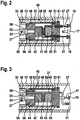
- the sensor lines 47 are led out of the sensor unit 40 on the connection module side. These are in accordance with FIG. 2 in the support member 45, two passages 51 are provided, through which the two sensor lines 47 are guided to the sensor terminals 16 out.
- the Glühstrom endeavor 27 is guided by the sensor unit 40.
- the pressure transfer piece 44 has a first passage 52 for passing the Glühstromtechnisch 27 for GlühstromWallet 24 out and the support member 45 a second passage 53 for passing the Glühstrom réelle 27 to the high-current terminal 17 toward.
- the Glühstrom réelle 27 guided substantially axially through the sensor unit 30 has a first 90 degree bend on the glow plug side and a second 90 degree bend on the connection side, so that the glow current line 27 can be guided axially through the sensor unit 40.
- a radial bore is introduced into the connection-side end portion 25 of the GlühstromWallets 24, in which the first 90-degree bend of Glühstromtechnisch 27 introduced and contacted there is electrically.
- the glow plug 21 is mounted axially displaceably in the glow module housing 13 by means of the flexurally elastic diaphragm 32. Furthermore, there is a power transmission from the glow plug 21 to the pressure transmission piece 44 of the sensor unit 40 instead.
- the support tube 22 fixedly connected to the glow plug 21 is extended with the connection sleeve 34 axially in the direction of the sensor unit 40 with an end section 55.
- the extended end portion 55 is placed on a formed on the pressure transmitting piece 44 collar and connected there by means of a first weld 56 with the pressure transmitting piece 44.
- the support tube 22 and the connecting sleeve 34 are firmly connected by means of a second weld seam 57.
- Within the end portion 55 thus forms a wood-cylindrical receiving space 58, in which the connection-side end portion 25 of the Glühstromnaps 24 is exposed and contacted there with the Glühstrom effet 27.
- the flexurally elastic membrane 32 is connected to the sensor housing 33 by means of a third weld seam 59.
- the sensor housing 33 is welded to the support element 45 by means of a fourth weld 61.
- the second weld 49 for connecting the clamping sleeve 46 and the fourth weld 61 for connecting the Sensorgeophüses 33 are performed at different diameters of the support member 45.
- annular gap 36 serves to provide a friction-free distance for the axial displacement of the connecting sleeve 34 and the resilient clamping sleeve 34 relative to the housing-fixed sensor housing 33.
- an outer support portion 64 is formed on the sensor housing 33, which is adapted to the outer diameter of the glow module housing 13 with the outer diameter is.
- the support portion 64 forms a connection point on the sensor housing 13, with which the sensor housing 33 is connected to the glow module housing 13 by means of another weld 62.
- the further weld 62 and the third weld 59 are designed to seal circumferentially.
- the bias voltage for the pressure sensor 41 is thus applied by the clamping sleeve 46 and not by the spring force of the flexurally elastic membrane 32.
- the bias for the pressure sensor 41 outside the annealing and pressure measuring module 11 on the preassembled sensor unit 40 is adjustable.
- the bias of the pressure sensor 41 is thereby not influenced by the spring force of the resilient membrane 32 and also not by the subsequent assembly steps in the insertion of the annealing and pressure measuring module 11 in the Glühmodulgephase 13.
- the prevailing pressure in the combustion chamber which exerts a compressive force acting as a pressure transducer glow plug 21 causes due to the flexurally elastic membrane 32 of the glow plug 21 with the support tube 22 and the connecting sleeve 34 an axial movement relative to the firmly fixed in the cylinder head Glühmodulgephaseuse 13 along the Longitudinal axis of the Druckmessglühkerze performs.
- the pressure force acts on the pressure transmission piece 44 and this presses due to the elastic effect of the clamping sleeve 46 via the first pressure piece 42 on the pressure sensor 41, which is supported via the second pressure piece 43 on the fixedly connected to the sensor housing 33 and thereby fixed support member 45.
Description
- Die Erfindung betrifft eine Druckmessglühkerze zum Einsetzen in einen Zylinderkopf einer Brennkraftmaschine mit den Merkmalen des Oberbegriffs des Anspruchs 1.
- Eine derartige Druckmessglühkerze ist aus
WO 2007/096208 A1 bekannt, bei der in einem Gehäuse ein Glühstift zum Zünden eines Verbrennungsgemisches einer Brennkraftmaschine und eine Druckmesseinrichtung mit einem Drucksensor zur Erfassung eines Brennraumdrucks der Brennkraftmaschine angeordnet sind. Der Glühstift ist dem Brennraumdruck ausgesetzt ist und überträgt als Druckaufnehmer den Brennraumdruck auf den Drucksensor, wobei der Drucksensor zwischen dem als Druckaufnehmer wirkenden Glühstift und einem Stützelement in einem Sensorgehäuse aufgenommen ist. Zwischen dem Sensorgehäuse und dem als Druckaufnehmer dienenden Glühstift ist eine biegeelastische Membran angeordnet, die die erforderliche axiale Längsbewegung des Glühstifts zur Druckübertragung ermöglicht und die gleichzeitig die erforderliche Vorspannkraft für den Drucksensor aufbringt. Dadurch wirken sich die bei der Montage des Glüh- und Druckmessmoduls auf die biegeelastische Membran einwirkenden Kräfte auch auf die Vorspannung des Drucksensors aus. - Weiterer relevanter Stand der Technik ist aus WO 2009/146565, DE 10 2006 008639 und DE 10 2006 049019 bekannt.
- Die Erfindung mit den kennzeichnenden Merkmalen des Anspruchs 1 hat den Vorteil, dass ein Glüh- und Druckmessmodul geschaffen wurde, bei dem der Drucksensor mittels einer zusätzlich zum Sensorgehäuse verwendeten Spannhülse zwischen dem Druckübertragungsstück und dem Stützelement vorgespannt wird. Dadurch bleibt die Vorspannkraft für den Drucksensor beim Einbau des Glüh- und Druckmessmoduls in das Gehäuse der Druckmessglühkerze unbeeinflusst.
- Vorteilhafte Weiterbildungen der Erfindung sind durch die Maßnahmen der Unteransprüche möglich.
- Die Spannhülse, das Druckübertragungsstück, das Stützelement sowie der davon umgebene Drucksensor bilden eine vormontierte Sensoreinheit, die in einen vom Brennraum abgewandten Endabschnitt des Sensorgehäuses einsetzbar ist. Dadurch ist die Sensoreinheit unabhängig vom Glüh- und Druckmessmodul montierbar. Die auf die biegeelastische Membran einwirkenden Kräfte bei der Montage wirken sich somit nicht auf die Vorspannung des Drucksensors aus. Das Stützelement erhält seiner gehäusefesten Fixierung dadurch, indem das Sensorgehäuse mit einem vom Brennraum abgewandten Endabschnitt mit dem Stützelement und an einem dem Brennraum zugewandten Endabschnitt mit dem Gehäuse der Druckmessglühkerze verbunden ist. Dadurch wird gleichzeitig die Sensoreinheit im Sensorgehäuse gehäusefest fixiert.
- Zum Ausüben einer axialen Längsbewegung zur Druckübertragung ist der Glühstift mittels der biegeelastischen Membran an einem dem Brennraum zugewandten Endabschnitt mit dem Sensorgehäuses verbunden. Zur Kraftübertragung ist am Druckübertragungsstück eine Verbindungshülse angeflanscht, die den Glühstift am vom Brennraum abgewandten Endabschnitt umgibt und die zumindest mittelbar mit dem Glühstift verbunden ist.
- Zweckmäßigerweise bildet die Verbindungshülse glühstiftseitig einen Aufnahmeraum für einen Glühstromkontakt aus, in dem der Glühstromkontakt mit einer Glühstromleitung kontaktiert ist. Die Glühstromleitung wird dabei durch die Sensoreinheit geführt, wobei dazu das Druckübertragungsstück eine erste Durchführung und das Stützelement eine zweite Durchführung aufweisen, durch welche die Glühstromleitung geführt wird, wobei die Glühstromleitung mit einem außerhalb der Sensoreinheit liegenden Hochstromanschluss kontaktierbar ist.
- Die mit dem Sensorgehäuse verbundenen Bauteile bilden ein Glüh- und Druckmessmodul, welches als vormontierbare Baueinheit in das Glühmodulgehäuse der Druckmessglühkerze einsetzbar ist. Das Glüh- und Druckmessmodul ist mittels einer am Sensorgehäuse ausgebildeten Befestigungsstelle mit dem Gehäuse der Druckmessglühkerze fest verbunden, wobei die Befestigungsstelle von einem am Sensorgehäuse ausgebildeten Stützabschnitt gebildet wird.
- Ein Ausführungsbeispiel der Erfindung ist in der Zeichnung dargestellt und in der nachfolgenden Beschreibung näher erläutert.
- Es zeigen:
- Figur 1
- eine Schnittdarstellung durch einen brennraumseitigen Abschnitt einer erfindungsgemäßen Druckmessglühkerze,
- Figur 2
- einen vergrößerten Ausschnitt X in
Figur 1 und - Figur 3
- den vergrößerten Ausschnitt X in
Figur 2 in einer um 180 Grad axial gedrehten Darstellung. - Die in
Figur 1 dargestellte Druckmessglühkerze vereint eine konventionelle Glühkerze 20 zum Einsatz in selbstzündenden Brennkraftmaschinen mit einer zusätzlichen Druckmessfunktion einer Druckmesseinrichtung 30 zur Erfassung eines Brennraumdrucks der Brennkraftmaschine. Die Druckmessglühkerze umfasst im Wesentlichen ein Glüh- und Druckmessmodul 11, welches in ein Gehäuse 13 der Druckmessglühkerze, das nachfolgend als Glühmodulgehäuse bezeichnet wird, untergebracht ist, und ein nicht näher dargestelltes Anschlussmodul 14, welches in einem Anschlussmodulgehäuse 15 untergebracht ist. Am Anschlussmodul 14 sind in das Glühmodulgehäuse 13 ragend und dort freiliegend zwei Sensoranschlüsse 16 für die Druckmesseinrichtung 30 und ein Hochstromanschluss 17 für die Glühkerze 20 ausgebildet, die im Anschlussmodul 14 zu nicht dargestellten elektrischen Verbindungen für einen Anschlussstecker führen. Im Anschlussmodul 14 kann eine Signalverarbeitungseinheit für die Vorverarbeitung der Signale der Druckmesseinrichtung 30 integriert sein. - Im Glüh- und Druckmessmodul 11 sind die Bauteile der Glühkerze 20 zum Zünden der Brennkraftmaschine und die Bauteile der Druckmesseinrichtung 30 zur Brennraumdruckmessung untergebracht. Die Glühkerze 20 umfasst einen aus dem Glühmodulgehäuse 13 brennraumseitig hervorstehenden Glühstift 21, welcher mit dem hervorstehenden Teil in den Brennraum der Brennkraftmaschine ragt und dadurch zugleich einen Druckaufnehmer für den im Brennraum herrschenden Druck bildet. Der Glühstift 21 ist im vorliegenden Ausführungsbeispiel ein keramischer Glühstift, in den ein nicht dargestelltes elektrisches Heizelement eingebettet ist. Der keramische Glühstift 21 ist von einem metallischen Stützrohr 22 umgeben. Das nicht dargestellt Heizelements ist zur Ausbildung eines Pols über eine außen liegende Kontaktierung mit dem Stützrohr 22 und zur Ausbildung des anderen Pols über eine elektrischen Verbindung 23 mit einem Glühstromkontakt 24 verbunden, wobei der Glühstromkontakt 24 als massiver Anschlussbolzen mit einem vom Brennraum abgewandten Endabschnitt 25 freiliegend aus dem Stützrohr 22 herausgeführt ist. Die elektrische Verbindung vom Glühstromkontakt 24 zum Hochstromanschluss 17 am Anschlussmodul 12 wird mittels einer Glühstromleitung 27 realisiert.
- Zwischen Stützrohr 22 und Glühstromkontakt 24 ist ferner ein elektrisch isolierendes Dichtelement 29 angeordnet. Es ist aber auch denkbar, den Glühstift 21 als metallisches Glührohr mit einer eingebetteten Heizwendel auszuführen.
- Die Druckmesseinrichtung 30 ist innerhalb des Glühmodulgehäuses 13 untergebracht und umfasst eine Sensoreinheit 40, eine biegeelastische Membran 32, ein Sensorgehäuse 33 und eine Verbindungshülse 34.
- Die Sensoreinheit 40 umfasst einen piezoelektrischen Drucksensor 41, ein glühstiftseitiges Druckstück 42, ein stützelementseitiges Druckstück 43, ein Druckübertragungsstück 44, ein Stützelement 45 und eine Spannhülse 46. Die Spannhülse 46 ist zwecks Realisierung einer Axialbewegung des Druckübertragsstücks 44 für die Kraftübertragung auf den Drucksensor 41 federelastisch ausgebildet. Dazu ist die Spannhülse 46 beispielsweise als Rohrfeder ausgeführt. Die Druckstücke 41, 42 sind aus einem elektrisch isolierenden Material hergestellt. Der Drucksensor 41 ist zwischen dem glühstiftseitigen Druckstück 42 und dem stützelementseitigen Druckstück 43 mittels einer Vorspannkraft, die von der Spannhülse 46 aufgebracht wird, positioniert. Der Drucksensor 41 weist zwei Sensorleitungen 47 auf, die mit den beiden Sensoranschlüssen 16 elektrisch verbunden sind.
- Das Druckübertragungsstück 44 und das Stützelement 45 sind mittels der federelastischen Spannhülse 46 verbunden, derart, dass einerseits auf den Drucksensor 41 die erforderliche Vorspannung wirkt und dass andererseits das Druckübertragungsstück 44 die für die Kraftübertragung auf den Drucksensor 41 notwendige Axialbewegung ausführen kann. Dadurch bildet die Spannhülse 46 unabhängig vom Sensorgehäuse 33 ein separates Spannelement für den Drucksensor 41 aus. Zur festen Verbindung der Spannhülse 46 mit dem Druckübertragungsstück 44 und dem Stützelement 45 ist die Spannhülse 46 am Druckübertragungsstücks 44 mittels einer ersten Schweißnaht 48 und am Stützelement 45 mittels einer zweiten Schweißnaht 49 verbunden. Dadurch bildet die Sensoreinheit 40 eine vom Glüh- und Druckmessmodul 11 separat vormontierbare Baueinheit.
- Die Sensorleitungen 47 werden anschlussmodulseitig aus der Sensoreinheit 40 herausgeführt. Dazu sind gemäß
Figur 2 im Stützelement 45 zwei Durchführungen 51 vorgesehen, durch die die beiden Sensorleitungen 47 zu den Sensoranschlüssen 16 hin geführt werden. - Zur Realisierung der Kontaktierung zwischen dem Glühstromkontakt 24 und dem Hochstromanschluss 17 wird die Glühstromleitung 27 durch die Sensoreinheit 40 geführt. Dazu weist gemäß
Figur 3 das Druckübertragungsstück 44 eine erste Durchführung 52 zum Durchführen der Glühstromleitung 27 zum Glühstromkontakt 24 hin und das Stützelement 45 eine zweite Durchführung 53 zum Durchführen der Glühstromleitung 27 zum Hochstromanschluss 17 hin auf. Die im Wesentlichen axial durch die Sensoreinheit 30 geführte Glühstromleitung 27 weist glühstiftseitig eine erste 90 Grad-Biegung und anschlussseitige eine zweite 90 Grad-Biegung auf, so dass die Glühstromleitung 27 axial durch die Sensoreinheit 40 geführt werden kann. Zur Kontaktierung mit dem Glühstromkontakt 24 ist eine radiale Bohrung in den anschlussseitigen Endabschnitt 25 des Glühstromkontakts 24 eingebracht, in die die erste 90 Grad-Biegung der Glühstromleitung 27 eingeführt und dort elektrisch kontaktiert ist. - Zur Realisierung der Druckübertragung vom Glühstift 21 auf den Drucksensor 41 ist der Glühstift 21 mittels der biegeelastischen Membran 32 axial verschiebbar im Glühmodulgehäuse 13 gelagert. Weiterhin findet eine Kraftübertragung vom Glühstift 21 auf das Druckübertragungsstück 44 der Sensoreinheit 40 statt. Dazu ist das fest mit dem Glühstift 21 verbundene Stützrohr 22 mit der Verbindungshülse 34 axial in Richtung der Sensoreinheit 40 mit einem Endabschnitt 55 verlängert. Der verlängerte Endabschnitt 55 ist an einem am Druckübertragungsstück 44 ausgebildeten Bund aufgesetzt und dort mittels einer ersten Schweißnaht 56 mit dem Druckübertragungsstück 44 verbunden. Das Stützrohr 22 und die Verbindungshülse 34 sind mittels einer zweiten Schweißnaht 57 fest verbunden. Innerhalb der Endabschnitts 55 bildet sich somit ein holzylinderförmiger Aufnahmeraum 58 aus, in dem der anschlussseitige Endabschnitt 25 des Glühstromkontakts 24 freiliegt und dort mit der Glühstromleitung 27 kontaktiert ist.
- Zur Ausbildung des Glüh- und Druckmessmoduls 11 ist die biegeelastische Membran 32 mit dem Sensorgehäuse 33 mittels einer dritten Schweißnaht 59 verbunden. Das Sensorgehäuse 33 ist am Stützelement 45 mittels einer vierten Schweißnaht 61 verschweißt. Die zweite Schweißnaht 49 zum Verbinden der Spannhülse 46 und die vierte Schweißnaht 61 zum Verbinden des Sensorgehäüses 33 sind an unterschiedlichen Durchmessern des Stützelements 45 ausgeführt. Dadurch liegt mit dem Glüh- Druckmessmodul 11 eine weitere vormontierbare Baueinheit vor, in der die Sensoreinheit 40 als erste vormontierbare Baueinheit aufgenommen ist und die in das Glühmodulgehäuse 13 eingesetzt und mit dem Glühmodulgehäuse 13 fest verbunden wird. Als zweckmäßig hat sich herausgestellt, dass zwischen der Außenwand der Verbindungshülse 34 und der Innenwand des Sensorgehäuses 33 sowie zwischen der Außenwand der Spannhülse 34 und der Innenwand des Sensorgehäuses 33 ein Ringspalt 36 ausgebildet ist. Der Ringspalt 36 dient dazu, um einen reibungsfreien Abstand für die axiale Verschiebung der Verbindungshülse 34 und der federelastische Spannhülse 34 relativ zum gehäusefesten Sensorgehäuse 33 zu schaffen.
- Zum Befestigen des Glüh- und Druckmessmoduls 11 im Glühmodulgehäuse 13 ist am Sensorgehäuse 33 ein äußerer Stützabschnitt 64 ausgebildet, der mit dem Außendurchmesser an den Innendurchmesser des Glühmodulgehäuses 13 angepasst ist. Der Stützabschnitt 64 bildet eine Verbindungsstelle am Sensorgehäuse 13, mit dem das Sensorgehäuse 33 am Glühmodulgehäuse 13 mittels einer weiteren Schweißnaht 62 verbunden ist. Die weitere Schweißnaht 62 und die dritte Schweißnaht 59 sind zur Abdichtung umlaufend ausgeführt.
- Die Vorspannung für den Drucksensor 41 wird somit von der Spannhülse 46 aufgebracht und nicht von der Federkraft der biegeelastischen Membran 32. Dadurch ist die Vorspannung für den Drucksensor 41 außerhalb des Glüh- und Druckmessmoduls 11 an der vormontierten Sensoreinheit 40 einstellbar. Die Vorspannung des Drucksensors 41 wird dadurch nicht von der Federkraft der federelastischen Membran 32 und auch nicht durch die nachfolgenden Montageschritte beim Einsetzten des Glüh- und Druckmessmoduls 11 in das Glühmodulgehäuse 13 beeinflusst.
- Der im Brennraum herrschende Druck, der eine Druckkraft auf den als Druckaufnehmer wirkenden Glühstift 21 ausübt, bewirkt, dass aufgrund der biegeelastischen Membran 32 der Glühstift 21 mit dem Stützrohr 22 und der Verbindungshülse 34 eine axiale Bewegung gegenüber dem fest im Zylinderkopf befestigen Glühmodulgehäuse 13 entlang der Längsachse der Druckmessglühkerze ausführt. Die Druckkraft wirkt auf das Druckübertragungsstück 44 und dieses drückt aufgrund der federelastischen Wirkung der Spannhülse 46 über das erste Druckstück 42 auf den Drucksensor 41, der sich über das zweite Druckstück 43 am fest mit dem Sensorgehäuse 33 verbundenen und dadurch fixierten Stützelement 45 abstützt.
Claims (7)
- Druckmessglühkerze mit einem Gehäuse (13), in dem ein Glühstift (21) zum Zünden eines Verbrennungsgemisches in einem Brennraum einer Brennkraftmaschine und eine Druckmesseinrichtung (30) mit einem Drucksensor (41) zur Erfassung eines Brennraumdrucks der Brennkraftmaschine angeordnet sind, wobei der als Druckaufnehmer wirkende Glühstift (21) mittels einer biegeelastischen Membran (32) mit dem Gehäuse (13) verbunden ist, wobei die im Brennraum auf den Glühstift (21) wirkende Kraft auf den Drucksensor (41) übertragen wird, wobei der Drucksensor (41) mittels einer Vorspannkraft zwischen einem Druckübertragungsstück (44) und einem Stützelement (45) angeordnet ist, und wobei das Stützelement (45) über ein Sensorgehäuse (33) mit dem Glühmodulgehäuse (13) gehäusefest fixiert ist, wobei zum Aufbringen der Vorspannkraft für den Drucksensor (41) eine Spannhülse (46) vorgesehen ist, die mit einem Ende mit dem Druckübertragungsstück (44) und mit dem anderen Ende mit dem Stützelement (45) verbunden ist, dadurch gekennzeichnet, dass die Spannhülse (46), das Druckübertragungsstück (44), das Stützelement (44) sowie der davon umgebene Drucksensor (41) eine vormontierte Sensoreinheit (40) bilden, und dass die vormontierte Sensoreinheit (40) an einen vom Brennraum abgewandten Endabschnitt in das Sensorgehäuses (33) einsetzbar ist, das Sensorgehäuse (33) mit einem vom Brennraum abgewandten Endabschnitt mit dem Stützelement (45) verbunden ist, und die Verbindung der Spannhülse (46) und die Verbindung des Sensorgehäuses (33) an unterschiedlichen Durchmessern am Stützelements (45) ausgeführt sind.
- Druckmessglühkerze nach Anspruch 1, dadurch gekennzeichnet, dass das Sensorgehäuse (33) an einem dem Brennraum zugewandten Endabschnitt mit der biegelastischen Membran (32) verbunden ist.
- Druckmessglühkerze nach Anspruch 1 oder 2, dadurch gekennzeichnet, dass das Sensorgehäuse (33) mittels einer Befestigungsstelle mit dem Gehäuse (13) fest verbunden ist.
- Druckmessglühkerze nach Anspruch 3, durch gekennzeichnet, dass dam Sensorgehäuse (33) ein Stützabschnitt (64) ausgebildet ist, welcher die Befestigungsstelle zum Befestigen am Gehäuse (13) bildet.
- Druckmessglühkerze nach Anspruch 1, dadurch gekennzeichnet, dass am Drückübertragungsstück (44) eine Verbindungshülse (34) angeflanscht ist, die zumindest mittelbar mit dem Glühstift (21) verbunden ist.
- Druckmessglühkerze nach Anspruch 5, dadurch gekennzeichnet, dass die Verbindungshülse (34) glühstiftseitig einen Aufnahmeraum (58) für einen Glühstromkontakt (24) ausbildet, in dem der Glühstromkontakt (24) mit einer Glühstromleitung (28) kontaktiert ist.
- Druckmessglühkerze nach Anspruch 6, dadurch gekennzeichnet, dass das Druckübertragungsstück (44) eine erste Durchführung (52) und das Stützelement (45) eine zweite Durchführung (53) für die Glühstromleitung (28) aufweisen, so dass die Glühstromleitung (28) durch die Sensoreinheit (40) hindurch geführt und mit einem außerhalb des Sensoreinheit (40) liegenden Hochstromanschluss (17) kontaktierbar ist.
Applications Claiming Priority (2)
| Application Number | Priority Date | Filing Date | Title |
|---|---|---|---|
| DE102012209237A DE102012209237A1 (de) | 2012-05-31 | 2012-05-31 | Druckmessglühkerze |
| PCT/EP2013/058958 WO2013178416A1 (de) | 2012-05-31 | 2013-04-30 | Druckmessglühkerze |
Publications (2)
| Publication Number | Publication Date |
|---|---|
| EP2856035A1 EP2856035A1 (de) | 2015-04-08 |
| EP2856035B1 true EP2856035B1 (de) | 2016-12-14 |
Family
ID=48190524
Family Applications (1)
| Application Number | Title | Priority Date | Filing Date |
|---|---|---|---|
| EP13718861.1A Not-in-force EP2856035B1 (de) | 2012-05-31 | 2013-04-30 | Druckmessglühkerze |
Country Status (7)
| Country | Link |
|---|---|
| US (1) | US9874195B2 (de) |
| EP (1) | EP2856035B1 (de) |
| JP (1) | JP5890938B2 (de) |
| CN (1) | CN104508379B (de) |
| DE (1) | DE102012209237A1 (de) |
| IN (1) | IN2014DN09912A (de) |
| WO (1) | WO2013178416A1 (de) |
Families Citing this family (7)
| Publication number | Priority date | Publication date | Assignee | Title |
|---|---|---|---|---|
| DE102015114811A1 (de) | 2015-09-04 | 2017-03-09 | Borgwarner Ludwigsburg Gmbh | Druckmessglühkerze |
| DE102015224166A1 (de) | 2015-12-03 | 2017-06-08 | Robert Bosch Gmbh | Sensorhalter für eine Druckmessglühkerze einer Brennkraftmaschine |
| DE102015224169A1 (de) | 2015-12-03 | 2017-06-08 | Robert Bosch Gmbh | Sensorhalter für eine Druckmessglühkerze einer Brennkraftmaschine |
| DE102015224168A1 (de) | 2015-12-03 | 2017-06-08 | Robert Bosch Gmbh | Vorrichtung zum Erfassen eines Brennraumdrucks in einem Brennraum einer Brennkraftmaschine |
| JP6686673B2 (ja) | 2016-04-27 | 2020-04-22 | 株式会社デンソー | 歪み検出センサ |
| DE102016114929B4 (de) * | 2016-08-11 | 2018-05-09 | Borgwarner Ludwigsburg Gmbh | Druckmessglühkerze |
| CN114323661A (zh) * | 2022-03-07 | 2022-04-12 | 江铃汽车股份有限公司 | 发动机缸内燃烧噪声测试分析方法及系统 |
Family Cites Families (24)
| Publication number | Priority date | Publication date | Assignee | Title |
|---|---|---|---|---|
| JP2559858Y2 (ja) * | 1992-12-09 | 1998-01-19 | 日本特殊陶業株式会社 | 圧力センサ |
| JP3911930B2 (ja) * | 1999-10-28 | 2007-05-09 | 株式会社デンソー | 燃焼圧センサ付きグロープラグ |
| JP3912352B2 (ja) | 2002-10-07 | 2007-05-09 | 株式会社デンソー | 燃焼圧センサ付きグロープラグ |
| DE10343521A1 (de) * | 2003-09-19 | 2005-04-21 | Beru Ag | Druckmessglühkerze für einen Dieselmotor |
| JP4708711B2 (ja) * | 2004-02-03 | 2011-06-22 | 株式会社デンソー | 圧力センサ |
| EP1637806B1 (de) * | 2004-09-15 | 2012-02-01 | Beru AG | Druckmessglühkerze für einen Dieselmotor |
| WO2006089446A1 (de) | 2005-02-24 | 2006-08-31 | Kistler Holding Ag | Bauteil für piezoelektrische kraft- oder drucksensoren, zusammengehalten von elektrisch isolierendem film |
| DE102005016463A1 (de) | 2005-04-11 | 2006-10-12 | Robert Bosch Gmbh | Glühstiftkerze mit integriertem Druckmesselement |
| FR2884299B1 (fr) | 2005-04-12 | 2007-06-29 | Siemens Vdo Automotive Sas | Bougie de prechauffage a capteur de pression integre et corps d'une telle bougie de prechauffage |
| DE102005035062A1 (de) * | 2005-07-27 | 2007-02-15 | Robert Bosch Gmbh | Vorrichtung zur Erfassung des Brennraumdrucks einer Brennkraftmaschine |
| DE102006008639A1 (de) | 2005-12-23 | 2007-06-28 | Robert Bosch Gmbh | Glühstiftkerze |
| DE102006008350A1 (de) | 2006-02-21 | 2007-08-30 | Robert Bosch Gmbh | Druckmesseinrichtung |
| DE102006008351A1 (de) * | 2006-02-21 | 2007-08-23 | Robert Bosch Gmbh | Druckmesseinrichtung |
| DE102006049079A1 (de) * | 2006-10-13 | 2008-04-17 | Robert Bosch Gmbh | Druckmesseinrichtung |
| DE102007049971A1 (de) | 2007-10-18 | 2009-04-23 | Robert Bosch Gmbh | Glühstiftkerze |
| DE102008017110B3 (de) | 2008-04-02 | 2009-09-10 | Beru Ag | Druckmessglühkerze |
| DE102008020509B4 (de) * | 2008-04-23 | 2010-02-25 | Beru Ag | Verfahren zur Herstellung einer Vorrichtung zur Ermittlung des Brennraumdrucks und eine solche Vorrichtung |
| EP2283334A1 (de) * | 2008-06-04 | 2011-02-16 | Kistler Holding AG | Drucksensor für messungen in einer kammer einer brennkraftmaschine |
| EP2138820B1 (de) * | 2008-06-25 | 2016-09-21 | Sensata Technologies, Inc. | Piezoresistiver Druckmessungsstecker für einen Verbrennungsmotor |
| US8217309B2 (en) * | 2008-12-15 | 2012-07-10 | Federal-Mogul Italy Srl. | Glow plug with pressure sensing canister |
| US8068558B2 (en) * | 2008-12-17 | 2011-11-29 | Nortel Networks Limited | Selective peak power reduction |
| DE102010038798A1 (de) * | 2010-08-02 | 2012-02-02 | Robert Bosch Gmbh | Vorrichtung zur Erfassung eines Brennraumdrucks |
| DE102011002596A1 (de) * | 2011-01-12 | 2012-07-12 | Robert Bosch Gmbh | Brennraumdrucksensor zur Erfassung eines Drucks in einem Brennraum einer Verbrennungskraftmaschine |
| KR101491945B1 (ko) * | 2011-02-25 | 2015-02-10 | 니혼도꾸슈도교 가부시키가이샤 | 연소압 검지센서 장착 글로 플러그 |
-
2012
- 2012-05-31 DE DE102012209237A patent/DE102012209237A1/de not_active Withdrawn
-
2013
- 2013-04-30 CN CN201380040354.2A patent/CN104508379B/zh not_active Expired - Fee Related
- 2013-04-30 EP EP13718861.1A patent/EP2856035B1/de not_active Not-in-force
- 2013-04-30 IN IN9912DEN2014 patent/IN2014DN09912A/en unknown
- 2013-04-30 WO PCT/EP2013/058958 patent/WO2013178416A1/de active Application Filing
- 2013-04-30 JP JP2015514396A patent/JP5890938B2/ja not_active Expired - Fee Related
- 2013-04-30 US US14/404,486 patent/US9874195B2/en not_active Expired - Fee Related
Non-Patent Citations (1)
| Title |
|---|
| None * |
Also Published As
| Publication number | Publication date |
|---|---|
| IN2014DN09912A (de) | 2015-08-14 |
| US9874195B2 (en) | 2018-01-23 |
| EP2856035A1 (de) | 2015-04-08 |
| JP2015525334A (ja) | 2015-09-03 |
| WO2013178416A1 (de) | 2013-12-05 |
| JP5890938B2 (ja) | 2016-03-22 |
| CN104508379A (zh) | 2015-04-08 |
| US20150136054A1 (en) | 2015-05-21 |
| CN104508379B (zh) | 2016-12-21 |
| DE102012209237A1 (de) | 2013-12-05 |
Similar Documents
| Publication | Publication Date | Title |
|---|---|---|
| EP2856035B1 (de) | Druckmessglühkerze | |
| EP1989485B1 (de) | Druckmesseinrichtung | |
| EP1517086B1 (de) | Druckmessglühkerze für einen Dieselmotor | |
| EP1794500B1 (de) | Glühstiftkerze mit elastisch gelagertem glühstift | |
| EP2102620B1 (de) | Druckmesseinrichtung | |
| EP1364123B1 (de) | Befestigungsvorrichtung | |
| DE102006008350A1 (de) | Druckmesseinrichtung | |
| WO2006072514A1 (de) | Stahlmembran für brennraumdrucksensoren | |
| EP2812635A1 (de) | Druckmessglühkerze | |
| EP3018337A1 (de) | Kraftstoffinjektor | |
| EP2601497A1 (de) | Vorrichtung zur erfassung eines brennraumdrucks einer brennkraftmaschine | |
| WO2009067833A2 (de) | Bauteil für kraft- oder druckmessungen und sensor umfassend ein solches bauteil | |
| EP1875135B1 (de) | Glühstiftkerze mit brennraumdrucksensor und dichtelement | |
| WO2006069900A1 (de) | Vorrichtung zur durchführung elektrischer anschlusskabel | |
| EP2791581A1 (de) | Druckmessglühkerze | |
| DE102006049079A1 (de) | Druckmesseinrichtung | |
| EP1891412A1 (de) | Integrierter brennraumdrucksensor | |
| EP3384264B1 (de) | Verfahren zur herstellung einer vorrichtung zur erfassung mindestens einer eigenschaft eines fluiden mediums in einem messraum | |
| DE102011088474A1 (de) | Druckmesseinrichtung, insbesondere Druckmessglühkerze | |
| WO2012146429A1 (de) | Vorrichtung zur erfassung eines drucks, insbesondere eines brennraumdrucks einer brennkraftmaschine | |
| WO2014067722A1 (de) | Miniaturisierter brennraumdrucksensor mit zugvorgespanntem sensorgehäuse | |
| EP2702379B1 (de) | Vorrichtung zur erfassung eines drucks, insbesondere eines brennraumdrucks einer brennkraftmaschine | |
| DE102013212298A1 (de) | Glühstiftkerze | |
| EP2884093A1 (de) | Sensoreinrichtung zur Kraft- oder Druckerfassung, Verfahren zum Herstellen einer Sensoreinrichtung und Kraftstoffinjektor mit einer Sensoreinrichtung | |
| DE102005039548A1 (de) | Piezoaktor mit einer Steckverbindung |
Legal Events
| Date | Code | Title | Description |
|---|---|---|---|
| PUAI | Public reference made under article 153(3) epc to a published international application that has entered the european phase |
Free format text: ORIGINAL CODE: 0009012 |
|
| 17P | Request for examination filed |
Effective date: 20150105 |
|
| AK | Designated contracting states |
Kind code of ref document: A1 Designated state(s): AL AT BE BG CH CY CZ DE DK EE ES FI FR GB GR HR HU IE IS IT LI LT LU LV MC MK MT NL NO PL PT RO RS SE SI SK SM TR |
|
| AX | Request for extension of the european patent |
Extension state: BA ME |
|
| DAX | Request for extension of the european patent (deleted) | ||
| REG | Reference to a national code |
Ref country code: DE Ref legal event code: R079 Ref document number: 502013005738 Country of ref document: DE Free format text: PREVIOUS MAIN CLASS: F23Q0007000000 Ipc: F02P0019020000 |
|
| RIC1 | Information provided on ipc code assigned before grant |
Ipc: F02P 19/02 20060101AFI20160719BHEP Ipc: F23Q 7/00 20060101ALI20160719BHEP |
|
| GRAP | Despatch of communication of intention to grant a patent |
Free format text: ORIGINAL CODE: EPIDOSNIGR1 |
|
| INTG | Intention to grant announced |
Effective date: 20160902 |
|
| GRAS | Grant fee paid |
Free format text: ORIGINAL CODE: EPIDOSNIGR3 |
|
| GRAA | (expected) grant |
Free format text: ORIGINAL CODE: 0009210 |
|
| AK | Designated contracting states |
Kind code of ref document: B1 Designated state(s): AL AT BE BG CH CY CZ DE DK EE ES FI FR GB GR HR HU IE IS IT LI LT LU LV MC MK MT NL NO PL PT RO RS SE SI SK SM TR |
|
| REG | Reference to a national code |
Ref country code: GB Ref legal event code: FG4D Free format text: NOT ENGLISH |
|
| REG | Reference to a national code |
Ref country code: CH Ref legal event code: EP |
|
| REG | Reference to a national code |
Ref country code: IE Ref legal event code: FG4D Free format text: LANGUAGE OF EP DOCUMENT: GERMAN |
|
| REG | Reference to a national code |
Ref country code: AT Ref legal event code: REF Ref document number: 853828 Country of ref document: AT Kind code of ref document: T Effective date: 20170115 |
|
| REG | Reference to a national code |
Ref country code: DE Ref legal event code: R096 Ref document number: 502013005738 Country of ref document: DE |
|
| PG25 | Lapsed in a contracting state [announced via postgrant information from national office to epo] |
Ref country code: LV Free format text: LAPSE BECAUSE OF FAILURE TO SUBMIT A TRANSLATION OF THE DESCRIPTION OR TO PAY THE FEE WITHIN THE PRESCRIBED TIME-LIMIT Effective date: 20161214 |
|
| REG | Reference to a national code |
Ref country code: LT Ref legal event code: MG4D |
|
| REG | Reference to a national code |
Ref country code: NL Ref legal event code: MP Effective date: 20161214 |
|
| REG | Reference to a national code |
Ref country code: FR Ref legal event code: PLFP Year of fee payment: 5 |
|
| PG25 | Lapsed in a contracting state [announced via postgrant information from national office to epo] |
Ref country code: NO Free format text: LAPSE BECAUSE OF FAILURE TO SUBMIT A TRANSLATION OF THE DESCRIPTION OR TO PAY THE FEE WITHIN THE PRESCRIBED TIME-LIMIT Effective date: 20170314 Ref country code: GR Free format text: LAPSE BECAUSE OF FAILURE TO SUBMIT A TRANSLATION OF THE DESCRIPTION OR TO PAY THE FEE WITHIN THE PRESCRIBED TIME-LIMIT Effective date: 20170315 Ref country code: LT Free format text: LAPSE BECAUSE OF FAILURE TO SUBMIT A TRANSLATION OF THE DESCRIPTION OR TO PAY THE FEE WITHIN THE PRESCRIBED TIME-LIMIT Effective date: 20161214 Ref country code: SE Free format text: LAPSE BECAUSE OF FAILURE TO SUBMIT A TRANSLATION OF THE DESCRIPTION OR TO PAY THE FEE WITHIN THE PRESCRIBED TIME-LIMIT Effective date: 20161214 |
|
| PG25 | Lapsed in a contracting state [announced via postgrant information from national office to epo] |
Ref country code: HR Free format text: LAPSE BECAUSE OF FAILURE TO SUBMIT A TRANSLATION OF THE DESCRIPTION OR TO PAY THE FEE WITHIN THE PRESCRIBED TIME-LIMIT Effective date: 20161214 Ref country code: RS Free format text: LAPSE BECAUSE OF FAILURE TO SUBMIT A TRANSLATION OF THE DESCRIPTION OR TO PAY THE FEE WITHIN THE PRESCRIBED TIME-LIMIT Effective date: 20161214 Ref country code: FI Free format text: LAPSE BECAUSE OF FAILURE TO SUBMIT A TRANSLATION OF THE DESCRIPTION OR TO PAY THE FEE WITHIN THE PRESCRIBED TIME-LIMIT Effective date: 20161214 |
|
| PG25 | Lapsed in a contracting state [announced via postgrant information from national office to epo] |
Ref country code: NL Free format text: LAPSE BECAUSE OF FAILURE TO SUBMIT A TRANSLATION OF THE DESCRIPTION OR TO PAY THE FEE WITHIN THE PRESCRIBED TIME-LIMIT Effective date: 20161214 |
|
| PG25 | Lapsed in a contracting state [announced via postgrant information from national office to epo] |
Ref country code: IS Free format text: LAPSE BECAUSE OF FAILURE TO SUBMIT A TRANSLATION OF THE DESCRIPTION OR TO PAY THE FEE WITHIN THE PRESCRIBED TIME-LIMIT Effective date: 20170414 Ref country code: EE Free format text: LAPSE BECAUSE OF FAILURE TO SUBMIT A TRANSLATION OF THE DESCRIPTION OR TO PAY THE FEE WITHIN THE PRESCRIBED TIME-LIMIT Effective date: 20161214 Ref country code: CZ Free format text: LAPSE BECAUSE OF FAILURE TO SUBMIT A TRANSLATION OF THE DESCRIPTION OR TO PAY THE FEE WITHIN THE PRESCRIBED TIME-LIMIT Effective date: 20161214 Ref country code: RO Free format text: LAPSE BECAUSE OF FAILURE TO SUBMIT A TRANSLATION OF THE DESCRIPTION OR TO PAY THE FEE WITHIN THE PRESCRIBED TIME-LIMIT Effective date: 20161214 Ref country code: SK Free format text: LAPSE BECAUSE OF FAILURE TO SUBMIT A TRANSLATION OF THE DESCRIPTION OR TO PAY THE FEE WITHIN THE PRESCRIBED TIME-LIMIT Effective date: 20161214 |
|
| PG25 | Lapsed in a contracting state [announced via postgrant information from national office to epo] |
Ref country code: IT Free format text: LAPSE BECAUSE OF FAILURE TO SUBMIT A TRANSLATION OF THE DESCRIPTION OR TO PAY THE FEE WITHIN THE PRESCRIBED TIME-LIMIT Effective date: 20161214 Ref country code: PT Free format text: LAPSE BECAUSE OF FAILURE TO SUBMIT A TRANSLATION OF THE DESCRIPTION OR TO PAY THE FEE WITHIN THE PRESCRIBED TIME-LIMIT Effective date: 20170414 Ref country code: PL Free format text: LAPSE BECAUSE OF FAILURE TO SUBMIT A TRANSLATION OF THE DESCRIPTION OR TO PAY THE FEE WITHIN THE PRESCRIBED TIME-LIMIT Effective date: 20161214 Ref country code: ES Free format text: LAPSE BECAUSE OF FAILURE TO SUBMIT A TRANSLATION OF THE DESCRIPTION OR TO PAY THE FEE WITHIN THE PRESCRIBED TIME-LIMIT Effective date: 20161214 Ref country code: SM Free format text: LAPSE BECAUSE OF FAILURE TO SUBMIT A TRANSLATION OF THE DESCRIPTION OR TO PAY THE FEE WITHIN THE PRESCRIBED TIME-LIMIT Effective date: 20161214 Ref country code: BG Free format text: LAPSE BECAUSE OF FAILURE TO SUBMIT A TRANSLATION OF THE DESCRIPTION OR TO PAY THE FEE WITHIN THE PRESCRIBED TIME-LIMIT Effective date: 20170314 |
|
| REG | Reference to a national code |
Ref country code: DE Ref legal event code: R097 Ref document number: 502013005738 Country of ref document: DE |
|
| PLBE | No opposition filed within time limit |
Free format text: ORIGINAL CODE: 0009261 |
|
| STAA | Information on the status of an ep patent application or granted ep patent |
Free format text: STATUS: NO OPPOSITION FILED WITHIN TIME LIMIT |
|
| 26N | No opposition filed |
Effective date: 20170915 |
|
| PG25 | Lapsed in a contracting state [announced via postgrant information from national office to epo] |
Ref country code: DK Free format text: LAPSE BECAUSE OF FAILURE TO SUBMIT A TRANSLATION OF THE DESCRIPTION OR TO PAY THE FEE WITHIN THE PRESCRIBED TIME-LIMIT Effective date: 20161214 |
|
| REG | Reference to a national code |
Ref country code: CH Ref legal event code: PL |
|
| GBPC | Gb: european patent ceased through non-payment of renewal fee |
Effective date: 20170430 |
|
| REG | Reference to a national code |
Ref country code: IE Ref legal event code: MM4A |
|
| PG25 | Lapsed in a contracting state [announced via postgrant information from national office to epo] |
Ref country code: MC Free format text: LAPSE BECAUSE OF FAILURE TO SUBMIT A TRANSLATION OF THE DESCRIPTION OR TO PAY THE FEE WITHIN THE PRESCRIBED TIME-LIMIT Effective date: 20161214 |
|
| PG25 | Lapsed in a contracting state [announced via postgrant information from national office to epo] |
Ref country code: LI Free format text: LAPSE BECAUSE OF NON-PAYMENT OF DUE FEES Effective date: 20170430 Ref country code: SI Free format text: LAPSE BECAUSE OF FAILURE TO SUBMIT A TRANSLATION OF THE DESCRIPTION OR TO PAY THE FEE WITHIN THE PRESCRIBED TIME-LIMIT Effective date: 20161214 Ref country code: GB Free format text: LAPSE BECAUSE OF NON-PAYMENT OF DUE FEES Effective date: 20170430 Ref country code: CH Free format text: LAPSE BECAUSE OF NON-PAYMENT OF DUE FEES Effective date: 20170430 Ref country code: LU Free format text: LAPSE BECAUSE OF NON-PAYMENT OF DUE FEES Effective date: 20170430 |
|
| REG | Reference to a national code |
Ref country code: BE Ref legal event code: MM Effective date: 20170430 |
|
| REG | Reference to a national code |
Ref country code: FR Ref legal event code: PLFP Year of fee payment: 6 |
|
| PG25 | Lapsed in a contracting state [announced via postgrant information from national office to epo] |
Ref country code: IE Free format text: LAPSE BECAUSE OF NON-PAYMENT OF DUE FEES Effective date: 20170430 |
|
| PG25 | Lapsed in a contracting state [announced via postgrant information from national office to epo] |
Ref country code: BE Free format text: LAPSE BECAUSE OF NON-PAYMENT OF DUE FEES Effective date: 20170430 |
|
| PGFP | Annual fee paid to national office [announced via postgrant information from national office to epo] |
Ref country code: FR Payment date: 20180424 Year of fee payment: 6 |
|
| PG25 | Lapsed in a contracting state [announced via postgrant information from national office to epo] |
Ref country code: MT Free format text: LAPSE BECAUSE OF FAILURE TO SUBMIT A TRANSLATION OF THE DESCRIPTION OR TO PAY THE FEE WITHIN THE PRESCRIBED TIME-LIMIT Effective date: 20161214 |
|
| PGFP | Annual fee paid to national office [announced via postgrant information from national office to epo] |
Ref country code: DE Payment date: 20180627 Year of fee payment: 6 |
|
| REG | Reference to a national code |
Ref country code: AT Ref legal event code: MM01 Ref document number: 853828 Country of ref document: AT Kind code of ref document: T Effective date: 20180430 |
|
| PG25 | Lapsed in a contracting state [announced via postgrant information from national office to epo] |
Ref country code: HU Free format text: LAPSE BECAUSE OF FAILURE TO SUBMIT A TRANSLATION OF THE DESCRIPTION OR TO PAY THE FEE WITHIN THE PRESCRIBED TIME-LIMIT; INVALID AB INITIO Effective date: 20130430 |
|
| PG25 | Lapsed in a contracting state [announced via postgrant information from national office to epo] |
Ref country code: CY Free format text: LAPSE BECAUSE OF FAILURE TO SUBMIT A TRANSLATION OF THE DESCRIPTION OR TO PAY THE FEE WITHIN THE PRESCRIBED TIME-LIMIT Effective date: 20161214 Ref country code: AT Free format text: LAPSE BECAUSE OF NON-PAYMENT OF DUE FEES Effective date: 20180430 |
|
| REG | Reference to a national code |
Ref country code: DE Ref legal event code: R119 Ref document number: 502013005738 Country of ref document: DE |
|
| PG25 | Lapsed in a contracting state [announced via postgrant information from national office to epo] |
Ref country code: MK Free format text: LAPSE BECAUSE OF FAILURE TO SUBMIT A TRANSLATION OF THE DESCRIPTION OR TO PAY THE FEE WITHIN THE PRESCRIBED TIME-LIMIT Effective date: 20161214 |
|
| PG25 | Lapsed in a contracting state [announced via postgrant information from national office to epo] |
Ref country code: DE Free format text: LAPSE BECAUSE OF NON-PAYMENT OF DUE FEES Effective date: 20191101 |
|
| PG25 | Lapsed in a contracting state [announced via postgrant information from national office to epo] |
Ref country code: FR Free format text: LAPSE BECAUSE OF NON-PAYMENT OF DUE FEES Effective date: 20190430 |
|
| PG25 | Lapsed in a contracting state [announced via postgrant information from national office to epo] |
Ref country code: TR Free format text: LAPSE BECAUSE OF FAILURE TO SUBMIT A TRANSLATION OF THE DESCRIPTION OR TO PAY THE FEE WITHIN THE PRESCRIBED TIME-LIMIT Effective date: 20161214 |
|
| PG25 | Lapsed in a contracting state [announced via postgrant information from national office to epo] |
Ref country code: AL Free format text: LAPSE BECAUSE OF FAILURE TO SUBMIT A TRANSLATION OF THE DESCRIPTION OR TO PAY THE FEE WITHIN THE PRESCRIBED TIME-LIMIT Effective date: 20161214 |