EP2854400A1 - Information processing apparatus, method of controlling an information processing apparatus, and recording medium - Google Patents
Information processing apparatus, method of controlling an information processing apparatus, and recording medium Download PDFInfo
- Publication number
- EP2854400A1 EP2854400A1 EP20140003236 EP14003236A EP2854400A1 EP 2854400 A1 EP2854400 A1 EP 2854400A1 EP 20140003236 EP20140003236 EP 20140003236 EP 14003236 A EP14003236 A EP 14003236A EP 2854400 A1 EP2854400 A1 EP 2854400A1
- Authority
- EP
- European Patent Office
- Prior art keywords
- projection
- projection surface
- information
- capturing
- target image
- Prior art date
- Legal status (The legal status is an assumption and is not a legal conclusion. Google has not performed a legal analysis and makes no representation as to the accuracy of the status listed.)
- Withdrawn
Links
Images


Classifications
-
- G—PHYSICS
- G06—COMPUTING OR CALCULATING; COUNTING
- G06T—IMAGE DATA PROCESSING OR GENERATION, IN GENERAL
- G06T5/00—Image enhancement or restoration
- G06T5/80—Geometric correction
-
- G—PHYSICS
- G06—COMPUTING OR CALCULATING; COUNTING
- G06T—IMAGE DATA PROCESSING OR GENERATION, IN GENERAL
- G06T3/00—Geometric image transformations in the plane of the image
- G06T3/20—Linear translation of whole images or parts thereof, e.g. panning
-
- G—PHYSICS
- G06—COMPUTING OR CALCULATING; COUNTING
- G06T—IMAGE DATA PROCESSING OR GENERATION, IN GENERAL
- G06T7/00—Image analysis
- G06T7/80—Analysis of captured images to determine intrinsic or extrinsic camera parameters, i.e. camera calibration
-
- G—PHYSICS
- G06—COMPUTING OR CALCULATING; COUNTING
- G06V—IMAGE OR VIDEO RECOGNITION OR UNDERSTANDING
- G06V10/00—Arrangements for image or video recognition or understanding
- G06V10/20—Image preprocessing
- G06V10/25—Determination of region of interest [ROI] or a volume of interest [VOI]
-
- H—ELECTRICITY
- H04—ELECTRIC COMMUNICATION TECHNIQUE
- H04N—PICTORIAL COMMUNICATION, e.g. TELEVISION
- H04N9/00—Details of colour television systems
- H04N9/12—Picture reproducers
- H04N9/31—Projection devices for colour picture display, e.g. using electronic spatial light modulators [ESLM]
- H04N9/3179—Video signal processing therefor
- H04N9/3185—Geometric adjustment, e.g. keystone or convergence
-
- H—ELECTRICITY
- H04—ELECTRIC COMMUNICATION TECHNIQUE
- H04N—PICTORIAL COMMUNICATION, e.g. TELEVISION
- H04N9/00—Details of colour television systems
- H04N9/12—Picture reproducers
- H04N9/31—Projection devices for colour picture display, e.g. using electronic spatial light modulators [ESLM]
- H04N9/3191—Testing thereof
- H04N9/3194—Testing thereof including sensor feedback
-
- G—PHYSICS
- G03—PHOTOGRAPHY; CINEMATOGRAPHY; ANALOGOUS TECHNIQUES USING WAVES OTHER THAN OPTICAL WAVES; ELECTROGRAPHY; HOLOGRAPHY
- G03B—APPARATUS OR ARRANGEMENTS FOR TAKING PHOTOGRAPHS OR FOR PROJECTING OR VIEWING THEM; APPARATUS OR ARRANGEMENTS EMPLOYING ANALOGOUS TECHNIQUES USING WAVES OTHER THAN OPTICAL WAVES; ACCESSORIES THEREFOR
- G03B21/00—Projectors or projection-type viewers; Accessories therefor
- G03B21/14—Details
- G03B21/147—Optical correction of image distortions, e.g. keystone
-
- G—PHYSICS
- G06—COMPUTING OR CALCULATING; COUNTING
- G06V—IMAGE OR VIDEO RECOGNITION OR UNDERSTANDING
- G06V10/00—Arrangements for image or video recognition or understanding
- G06V10/20—Image preprocessing
- G06V10/24—Aligning, centring, orientation detection or correction of the image
- G06V10/245—Aligning, centring, orientation detection or correction of the image by locating a pattern; Special marks for positioning
-
- G—PHYSICS
- G06—COMPUTING OR CALCULATING; COUNTING
- G06V—IMAGE OR VIDEO RECOGNITION OR UNDERSTANDING
- G06V10/00—Arrangements for image or video recognition or understanding
- G06V10/20—Image preprocessing
- G06V10/24—Aligning, centring, orientation detection or correction of the image
- G06V10/247—Aligning, centring, orientation detection or correction of the image by affine transforms, e.g. correction due to perspective effects; Quadrilaterals, e.g. trapezoids
-
- H—ELECTRICITY
- H04—ELECTRIC COMMUNICATION TECHNIQUE
- H04N—PICTORIAL COMMUNICATION, e.g. TELEVISION
- H04N9/00—Details of colour television systems
- H04N9/12—Picture reproducers
- H04N9/31—Projection devices for colour picture display, e.g. using electronic spatial light modulators [ESLM]
- H04N9/3141—Constructional details thereof
- H04N9/3147—Multi-projection systems
Definitions
- Embodiments described herein relate generally to an information processing apparatus and a method of controlling information processing apparatus of controlling display of an image to be projected by a projection unit.
- Alignment of the projection region of a projector is cumbersome. Especially when the projection surface is distant, a small change of the projector installation position greatly influences a projection position and shape on the projection surface. Thus, the alignment takes time every time the projector is installed. The alignment is also troublesome even at the time of projection in a general meeting room, and it is requested to shorten the projector installation time.
- Japanese Patent Laid-Open No. 11-327042 has disclosed a method of automatically adjusting an installation position while confirming a marker on a screen, and the position of the bright point of a laser pointer that is emitted by a projector.
- Embodiments described herein provide a technique capable of easily projecting a target image from a projection apparatus on an arbitrary projection surface in the same state as a past projection state.
- the present invention in its first aspect provides an information processing apparatus as specified in claims 1 to 9.
- the present invention in its second aspect provides a method of controlling an information processing apparatus as specified in claims 10 to 12.
- the present invention in its third aspect provides a recording medium as specified in claims 13 to 15.
- Fig. 1 is a block diagram showing the arrangement of an embodiment of a projector projection system according to the first embodiment.
- a projection unit 101 enlarges and projects, on a screen or wall surface in front of a projector, an arbitrary image input to the projector serving as a projection apparatus.
- a projection method for example, a liquid crystal panel transmits light to project an image, or an image displayed on a CRT is enlarged and projected using an optical system.
- the first embodiment does not limit these projection methods.
- An acquisition unit 102 acquires projection surface information of a projection surface on which the projection unit 101 projects a target image.
- An example of the projection surface information assumes a target image, and an image obtained by capturing, by a camera, a wall surface on which an image is projected. A case in which an image captured by a camera serving as a capturing apparatus is acquired as the projection surface information will be exemplified.
- the acquisition unit 102 acquires a captured image captured from a capturing position corresponding to a projection state of the projection unit 101.
- the projection state corresponds, for example, a place where the projection unit 101 is set, or projection direction of the projection unit 101.
- a detection unit 103 detects projection region information from projection surface information acquired by the acquisition unit 102.
- An example of the projection region information assumes projection surface information, and position information of a feature point group obtained by analyzing an image captured by the camera.
- a storage unit 104 stores projection region information detected by the detection unit 103.
- the projection region information is information indicating the position, on the projection surface, of a target image projected on the projection surface from the first position by the projection unit 101.
- the timing to store projection region information may be designated by the user by operating an input unit such as the button of the projector or a remote control accessory to the projector.
- projection region information may be stored automatically in synchronism with state transition of the projector such as the lapse of a predetermined time after the start of projection. In the following description, the user designates the timing to store projection region information.
- a decision unit 105 decides a projection correction parameter for correcting, based on projection region information detected by the detection unit 103 and projection region information already stored in the storage unit 104, an image to be projected from the projection unit 101.
- the projection correction parameter assumes at least one of various forms synchronized with projector functions, such as deformation information (shape), display position information, scaling information (size), and keystone correction information.
- a control unit 106 performs control for reflecting a projection correction parameter decided by the decision unit 105 in an image to be projected on the projection unit 101.
- the reflection form assumes various forms synchronized with projector functions, such as deformation, offset, scaling, and optical correction of an electrical image.
- the control unit 106 performs such control that the position, on the projection surface, of a target image to be projected on the projection surface from the second position by the projection unit 101 becomes a position corresponding to projection region information (first information).
- the control unit 106 controls the projection unit 101 based on projection region information stored in the storage unit 104, information about the projection surface acquired at a position corresponding to the first position, and information about the projection surface acquired at a position corresponding to the second position.
- the information about the projection surface is, for example, information of a feature point on the projection surface that is detected from an image obtained by capturing the projection surface.
- the projector projection system implemented as one of information processing apparatuses includes standard building components (for example, CPU, RAM, ROM, hard disk, external storage device, network interface, display, keyboard, and mouse) which are mounted in a general-purpose computer. These building components implement various functional arrangements shown in Fig. 1 . These functional arrangements can also be implemented by, for example, reading out a program stored in a memory such as the ROM and executing it by the CPU.
- standard building components for example, CPU, RAM, ROM, hard disk, external storage device, network interface, display, keyboard, and mouse
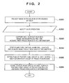
- Fig. 2 is a flowchart showing processing of storing the first projection region information according to the first embodiment. This processing concerns processing when the user projects an image on an arbitrary wall surface for the first time. This processing will be explained according to the flowchart together with an example in Figs. 3 and 4 .
- step S201 the user projects an image in a desired projection state (projection position and target image size) of the projector by using the projection unit 101.
- This projection state will be referred to as the first projection state.
- Fig. 3 shows an example of the first projection state.
- reference numeral 301 denotes a projector; 302, a wall surface of a building on which an image from the projector 301 is projected; and 303, a projection region of the image from the projector 301.
- the user performs alignment of the projection region 303 while adjusting the installation position of the projector 301 or using the projection position adjustment function of the projector 301. At this time, the position of the projection region 303 is adjusted with respect to the shape or design of the wall surface 302, implementing a projection state the user wants.
- step S202 a user operation notifying that the projection unit 101 has projected the image in a projection state the user wants is accepted.
- the user operation is accepted through, for example, an operation to an input unit such as the button of the projector or a remote control accessory to the projector.
- the embodiment does not limit these input units.
- the method of automatically generating a notification within the projector is, for example, a method of synchronizing with state transition of the projector a predetermined time after the start of projection.
- step S203 the acquisition unit 102 captures the wall surface on which the projection unit 101 has projected the image, and acquires the captured projection surface as the first projection surface information.
- the acquisition unit 102 captures a region 304 including the projection region 303 and peripheral wall surface 302, and acquires the captured projection surface as the first projection surface information.
- the first projection surface information corresponds to the first image obtained by capturing, from a position corresponding to the first position, the projection surface on which the target image has been projected.
- step S204 the projection is temporarily stopped, and the acquisition unit 102 captures again the wall surface and acquires the captured projection surface as basic projection surface information.
- Fig. 4 is a schematic view showing a state in which the projection is stopped. Since the projection from a projector 401 is stopped, only the wall surface serving as the projection destination is captured. As a region 402 captured at this time, the same region as the region 304 captured in step S203 can be captured. However, even when the regions 304 and 402 shift from each other, the following processing can be continued by, for example, executing correction processing of normalizing the acquired first projection surface information and basic projection surface information.
- step S205 the detection unit 103 detects the feature point group of the wall surface and the feature point group of the projection region. Details of this processing will be described later with reference to Fig. 5 .
- step S206 the storage unit 104 stores the feature point group of the wall surface, the feature point group of the projection region, the first projection surface information, and the basic projection surface information.
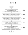
- Fig. 5 is a flowchart showing details of the processing of detecting the feature point group of the wall surface and the feature point group of the projection region according to the first embodiment. This processing corresponds to step S205 of Fig. 2 . This processing will be explained according to the flowchart together with an example in Figs. 6 to 9 .
- step S501 the detection unit 103 removes noise from the first projection surface information and basic projection surface information.
- This step is pre-processing for improving the processing accuracy in subsequent steps S502 and S503, and can be omitted in accordance with the capturing states of the first projection surface information and basic projection surface information.
- the noise removal algorithm for example, a method of applying a median filter to each pixel of the entire image is widely known.
- the embodiment does not limit the noise removal algorithm.
- an algorism which does not impair an abrupt change point (to be referred to as an edge hereinafter) of the density in an image can be selected.
- the same algorism is applicable to the first projection surface information and basic projection surface information.
- the median filter is a filter which outputs the median of pixel values in a given region. This filter has an effect of removing noise without impairing the edge.
- the detection unit 103 detects a plurality of feature points (group A) from the first projection surface information.
- the feature point detection algorithm a method of emphasizing an edge by applying a Laplacian filter to each pixel of the entire image, a KLT method, and the like are widely known.
- the embodiment does not limit the detection algorithm. Note that expression (1) represents an example of the Laplacian filter: 0 1 0 1 - 4 1 0 1 0
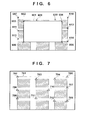
- Fig. 6 shows an example of the result of detecting feature points from the first projection surface information.
- the first projection surface information is acquired in step S203, and is equivalent to the region 304 shown in Fig. 3 .
- reference numeral 601 denotes a projection region; and 602, a wall surface. Feature points 603 to 614 surrounding the projection region 601 and wall surface 602 are detected.
- step S503 the detection unit 103 detects a plurality of feature points (group B) from the basic projection surface information.
- the detection algorithm and parameter used here are the same as those applied to the first projection surface information in step S502.
- Fig. 7 shows an example of the result of detecting feature points from the basic projection surface information.
- the basic projection surface information is acquired in step S204, and is equivalent to the region 402 shown in Fig. 4 .
- reference numeral 701 denotes a wall surface; and 702 to 712, detected feature points of the wall surface.
- step S504 the detection unit 103 compares the feature points (group A) with the feature points (group B) to detect the feature point group of the projection region. More specifically, feature points which do not exist in the feature points (group B) are extracted from the feature points (group A), and an estimated contour is applied to the projection region, thereby detecting the feature point group of the projection region. In the example of Figs. 6 and 7 , the feature points 603 to 606 for the projection region 601 are detected.
- Information detected in step S504 is information indicating the position, on the projection surface, of a target image projected on the projection surface by the projection unit 101.
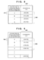
- Fig. 8 shows an example of a method of storing, in the storage unit 104, the detection result of the feature point group of the projection region that has been detected in step S504.
- a table 800 has rows by the number of detected feature points of the projection region. Coordinates (x:y) serving as position information of each feature point based on, as the origin, the upper left portion of the first projection surface information are stored in a column 801. For example, a row 802 corresponds to the feature point 603 of the projection region 601 in Fig. 6 .
- step S505 the detection unit 103 detects, from the feature points (group B), a feature point group of the wall surface that is positioned close outside the feature point group of the projection region. More specifically, the projection region is estimated from the feature point group of the projection region that has been detected in step S504 and is stored in the form shown in Fig. 8 . Then, feature points positioned outside the projection region, that is, feature points of the wall surface outside the projection region are detected. In the example of Figs. 6 and 7 , the feature points 702 to 709 for the wall surface 701 are detected. Note that the feature points 710 to 712 are determined to fall within the projection region, and are excluded.
- Fig. 9 shows an example of a method of storing, in the storage unit 104, the detection result of the feature point group of the wall surface that has been detected in step S505.
- a table 900 has rows by the number of detected feature points of the wall surface. The coordinates (x:y) of each feature point based on, as the origin, the upper left portion of the basic projection surface information are stored in a column 901. For example, a row 902 corresponds to the feature point 702 of the wall surface 701 in Fig. 7 .
- Fig. 10 is a flowchart showing processing of correcting and projecting the second projection region according to the first embodiment.
- This processing concerns processing when the user projects again an image on a wall surface on which he projected an image in the past.
- this processing is equivalent to processing of, after storing the first projection state described with reference to Fig. 2 , temporarily dismantling the projector and then installing it again. This processing will be explained according to the flowchart together with an example in Fig. 11 .
- step S1001 the user installs again the projector, and projects again an image by using the projection unit 101.
- This state will be referred to as the second projection state.
- Fig. 11 shows an example of the second projection state.
- the user installs a projector 1101 so that the projection state becomes the same as the first projection state.
- manual installation has limitations on the adjustment of the installation position and installation angle. As a result, the position and shape of a projection region 1103 projected on a wall surface 1102 become different from those of the projection region 303 projected in step S201.
- step S1002 the projection unit 101 accepts a user operation serving as a trigger to advance the process to step S1003 and subsequent steps.
- the user operation is accepted through, for example, an operation to an input unit such as the button of the projector or a remote control accessory to the projector.
- the embodiment does not limit these input units.
- the method of automatically generating a notification within the projector is, for example, a method of synchronizing with state transition of the projector a predetermined time after the start of projection.
- step S1003 the acquisition unit 102 captures the wall surface on which the projection unit 101 has projected an image, and acquires the captured projection surface as the second projection surface information.
- a region 1104 is captured, and the captured projection surface is acquired as the second projection surface information.
- the second projection surface information corresponds to the second image obtained by capturing, from a position corresponding to the second position, the projection surface on which the target image has been projected.
- step S1004 the detection unit 103 normalizes the second projection surface information by using the basic projection surface information, thereby obtaining the normalized second projection surface information. Details of this processing will be described later with reference to Fig. 12 .
- step S1005 the decision unit 105 decides a projection correction parameter. Details of this processing will be described later with reference to Fig. 15 .
- step S1006 the control unit 106 controls to reflect the projection correction parameter in the target image and project the target image.
- the reflection form of the projection correction parameter assumes various forms synchronized with projector functions, such as deformation, offset, scaling, and optical correction of an electrical image.
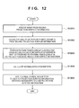
- Fig. 12 is a flowchart showing details of the processing of normalizing the second projection surface information by using the basic projection surface information, thereby obtaining the normalized second projection surface information according to the first embodiment.
- This processing corresponds to step S1004 of Fig. 10 .
- the normalized second projection surface information is the third image corrected so that the position of the feature point of the projection surface in the second projection surface information corresponds to the position of the feature point of the projection surface in the first projection surface information.
- This processing will be explained according to the flowchart together with an example in Figs. 13 and 14 .
- step S1201 the detection unit 103 removes noise from the second projection surface information. Details of this processing are the same as those of step S501.
- An algorithm to be applied can be the same as the algorithm applied to the first projection surface information and basic projection surface information.
- step S1202 the detection unit 103 detects a plurality of feature points (group C) from the second projection surface information. Details of this processing are the same as those in steps S502 and S503, and an algorithm to be applied is also the same.
- Fig. 13 shows an example of the result of detecting the feature point group of the wall surface in the second projection surface information.
- the second projection surface information is acquired in step S1003, and is equivalent to the region 1104 shown in Fig. 11 .
- reference numeral 1301 denotes a projection region; and 1302, a wall surface. Feature points surrounding the projection region 1301 and wall surface 1302 are detected.
- the detection unit 103 detects three or more feature points (group C) which have been detected from the second projection surface information and correspond to the feature points (group B) detected from the basic projection surface information.
- a KLT method is used as the method of detecting corresponding feature points from feature points (group B) and feature points (group C).
- the embodiment does not limit the detection algorithm. The following description continues on the assumption that, in the example of Fig. 13 , feature points 1303 to 1305 detected from the second projection surface information have been detected in correspondence with the feature points 702, 705, and 709 detected from the basic projection surface information, respectively.
- step S1204 the detection unit 103 decides normalization parameters for converting the second projection surface information into an image captured from the same position as that of the basic projection surface information.
- a, b, c, and d calculated by solving simultaneous equations are scaling/rotation parameters, and t x and ty are translation parameters. These parameters will be generically called normalization parameters.
- step S1205 the detection unit 103 applies the normalization parameters decided in step S1204 to the pixels of the entire projection surface represented by the second projection surface information, thereby obtaining the normalized second projection surface information.
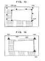
- Fig. 14 shows an example of the normalized second projection surface information.
- reference numeral 1401 denotes a normalized projection region; and 1402, a normalized wall surface.
- Plots 1403 to 1405 are obtained by normalizing the feature points 1303 to 1305 detected in step S1203, respectively. As a result, the coordinates of the plots 1403, 1404, and 1405 coincide with those of the feature points 702, 705, and 709 detected from the basic projection surface information.
- Fig. 15 is a flowchart showing details of the processing of deciding a projection correction parameter according to the first embodiment. This processing corresponds to step S1005 of Fig. 10 . This processing will be explained according to the flowchart together with an example in Figs. 16 and 17 .
- step S1501 the detection unit 103 detects a plurality of feature points (group D) from the normalized second projection surface information. Details of this processing are the same as steps S502, S503, and S1202, and an algorithm to be applied is the same.
- Fig. 16 shows an example of the detection result of the feature point group of the wall surface in the normalized second projection surface information.
- reference numeral 1601 denotes a projection region; and 1602, a wall surface. Feature points surrounding the projection region 1601 and wall surface 1602 are detected.
- step S1502 the detection unit 103 detects feature points (group D) which have been detected from the normalized second projection surface information and correspond to the feature points of the projection region detected from the first projection surface information.
- the feature points of the projection region have been detected in step S504 and stored in the form of the table 800.
- feature points 1603 to 1606 in Fig. 16 are detected.
- the decision unit 105 decides deformation parameters for deforming the projection region in the normalized second projection surface information into the projection region in the first projection surface information.
- the deformation parameters are calculated by substituting, into the affine matrix in equation (2), the coordinates of three pairs of feature points among the feature points detected in step S1502.
- x and y are the coordinates of the feature point of the projection region that has been detected from the normalized second projection surface information
- x' and y' are the coordinates of the feature point of the projection region that has been detected from the first projection surface information.
- a , b, c, and d calculated by solving simultaneous equations are scaling/rotation parameters
- t x and ty are translation parameters.
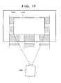
- Fig. 17 is a schematic view showing a projection state reflecting the projection correction parameter obtained as the result of processing in step S1006.
- a projector 1701 is moved from the position (central axis) of the projector 301 in the first projection state.
- the position of a projection region 1703 with respect to a wall surface 1702 is the same as the position of the projection region 303 with respect to the wall surface 302 in the first projection state.
- the decision unit 105 decides the projection correction parameter which reduces or cancels the difference between the position of a feature point indicated by projection region information detected by the detection unit 103, and that of a feature point indicated by projection region information already stored in the storage unit 104.
- the target image can be corrected so that the position of the target image in the first image corresponds to that of the target image in the third image.
- the target image corrected by the projection unit 101 is projected on the projection surface.
- the projection region can be automatically corrected (controlled) in the second and subsequent projection operations to project a target image.
- step S204 the capturing apparatus captures a wall surface to acquire basic projection surface information in a state in which projection is temporarily stopped. Then, in step S205, the feature points of the projection region and wall surface are detected from the first projection surface information and basic projection surface information.
- the present invention is not limited to this.
- the capturing apparatus may capture a wall surface to acquire basic projection surface information in a state in which an image different from one at the time of acquiring the first projection surface information is projected. Then, in step S205, the feature points of the projection region and wall surface may be detected from the first projection surface information and basic projection surface information.
- information representing the positional relationship between a projection region and a wall surface serving as a projection destination is stored at the time of the first projection operation.
- the projection region at the time of the second and subsequent projection operations is corrected using this information.
- a target image from the projector can be easily projected in the same state as the past projection state.
- the projector is easily installed.
- the second embodiment will be described mainly for a difference from the first embodiment.
- the technical scope of the present invention is not limited to this embodiment.
- the second embodiment assumes a case in which processing of storing the first projection region information shown in Fig. 2 is executed independently a plurality of times. For example, an image is projected on a plurality of different wall surfaces by using a projector, and pieces of first projection region information are stored for the respective scenes.
- a detection unit 103 stores the feature point groups of the respective wall surfaces, the feature point groups of the respective projection regions, and pieces of basic projection surface information.
- Fig. 18 is a flowchart showing processing of correcting and projecting the second projection region according to the second embodiment.
- the second embodiment assumes that a storage unit 104 stores the first information (first basic projection surface information) indicating the position, on the projection surface, of a target image projected on the projection surface from the first position by a projection unit 101. Also, assume that the storage unit 104 stores the second information (second basic projection surface information) indicating the position, on the projection surface, of the target image projected on the projection surface from the third position different from the first position by the projection unit 101.
- step S1801 the projector is installed again, and then the projection unit 101 projects again an image. This state will be referred to as the second projection state.
- step S1802 the projection unit 101 accepts a user operation serving as a trigger to advance the process to step S1803 and subsequent steps.
- step S1803 an acquisition unit 102 captures the wall surface on which the image has been projected, and acquires the captured projection surface as the second projection surface information.
- step S1804 the detection unit 103 selects basic projection surface information similar to the second projection surface information from pieces of basic projection surface information stored in the storage unit 104.
- the method of selecting similar basic projection surface information it may be selected in accordance with a selection instruction from the user.
- basic projection surface information having a higher degree of similarity with the second projection surface information than other pieces of basic projection surface information may be selected using a well-known algorithm such as a genetic algorithm.
- step S1805 the detection unit 103 normalizes the second projection surface information by using the selected basic projection surface information, thereby obtaining the normalized second projection surface information.
- step S1806 a decision unit 105 decides a projection correction parameter.
- a control unit 106 controls to reflect the projection correction parameter in the target image and project the target image.
- the reflection form of the projection correction parameter assumes various forms synchronized with projector functions, such as deformation, offset, scaling, and optical correction of an electrical image.
- the projection region can be automatically corrected (controlled) in the second and subsequent projection operations to project an image, in addition to the effects described in the first embodiment.
- control unit 106 controls the projection unit 101 based on the second information, information acquired at a position corresponding to the first position by the acquisition unit, and information acquired at the third position by the acquisition unit.
- the control unit 106 controls the projection unit 101 so that the position, on the projection surface, of a target image to be projected from the third position becomes a position corresponding to the first information.
- projection mapping has been exemplified and explained.
- the third embodiment is effective even in another use form in a meeting room, a home theater, or the like.
- Embodiment(s) of the present invention can also be realized by a computer of a system or apparatus that reads out and executes computer executable instructions (e.g., one or more programs) recorded on a storage medium (which may also be referred to more fully as a "non-transitory computer-readable storage medium") to perform the functions of one or more of the above-described embodiment(s) and/or that includes one or more circuits (e.g., application specific integrated circuit (ASIC)) for performing the functions of one or more of the above-described embodiment(s), and by a method performed by the computer of the system or apparatus by, for example, reading out and executing the computer executable instructions from the storage medium to perform the functions of one or more of the above-described embodiment(s) and/or controlling the one or more circuits to perform the functions of one or more of the above-described embodiment(s).
- computer executable instructions e.g., one or more programs
- a storage medium which may also be referred to more fully as a "
- the computer may comprise one or more processors (e.g., central processing unit (CPU), micro processing unit (MPU)) and may include a network of separate computers or separate processors to read out and execute the computer executable instructions.
- the computer executable instructions may be provided to the computer, for example, from a network or the storage medium.
- the storage medium may include, for example, one or more of a hard disk, a random-access memory (RAM), a read only memory (ROM), a storage of distributed computing systems, an optical disk (such as a compact disc (CD), digital versatile disc (DVD), or Blu-ray Disc (BD)TM), a flash memory device, a memory card, and the like.
- the embodiment becomes effective by connecting the acquisition unit via a communication unit to a detection unit arranged on a projector.
- a target image from the projection apparatus can be easily projected on an arbitrary projection surface in the same state as a past projection state. Also, according to the above-described embodiments, the projection apparatus can be easily installed.
Landscapes
- Engineering & Computer Science (AREA)
- Physics & Mathematics (AREA)
- General Physics & Mathematics (AREA)
- Theoretical Computer Science (AREA)
- Multimedia (AREA)
- Signal Processing (AREA)
- Geometry (AREA)
- Computer Vision & Pattern Recognition (AREA)
- Projection Apparatus (AREA)
- Transforming Electric Information Into Light Information (AREA)
- Controls And Circuits For Display Device (AREA)
Applications Claiming Priority (1)
| Application Number | Priority Date | Filing Date | Title |
|---|---|---|---|
| JP2013200525A JP6289003B2 (ja) | 2013-09-26 | 2013-09-26 | 情報処理装置及びその制御方法、プログラム |
Publications (1)
| Publication Number | Publication Date |
|---|---|
| EP2854400A1 true EP2854400A1 (en) | 2015-04-01 |
Family
ID=51726278
Family Applications (1)
| Application Number | Title | Priority Date | Filing Date |
|---|---|---|---|
| EP20140003236 Withdrawn EP2854400A1 (en) | 2013-09-26 | 2014-09-18 | Information processing apparatus, method of controlling an information processing apparatus, and recording medium |
Country Status (4)
| Country | Link |
|---|---|
| US (1) | US10134118B2 (enExample) |
| EP (1) | EP2854400A1 (enExample) |
| JP (1) | JP6289003B2 (enExample) |
| CN (1) | CN104519293A (enExample) |
Cited By (1)
| Publication number | Priority date | Publication date | Assignee | Title |
|---|---|---|---|---|
| WO2019096339A1 (de) * | 2017-11-17 | 2019-05-23 | domeprojection.com GmbH | Verfahren zur automatischen wiederherstellung eines eingemessenen zustands eines projektionssystems |
Families Citing this family (15)
| Publication number | Priority date | Publication date | Assignee | Title |
|---|---|---|---|---|
| JP5924020B2 (ja) * | 2012-02-16 | 2016-05-25 | セイコーエプソン株式会社 | プロジェクター、及び、プロジェクターの制御方法 |
| JP6631181B2 (ja) * | 2015-11-13 | 2020-01-15 | セイコーエプソン株式会社 | 画像投射システム、プロジェクター、及び、画像投射システムの制御方法 |
| US11035667B2 (en) * | 2016-09-14 | 2021-06-15 | Erez Halahmi | Monitoring system and method for controlling process of surface treatment for construction |
| CN106454542A (zh) * | 2016-10-31 | 2017-02-22 | 北京小米移动软件有限公司 | 投影处理方法及装置 |
| JP6897092B2 (ja) * | 2016-12-22 | 2021-06-30 | カシオ計算機株式会社 | 投影制御装置、投影制御方法及びプログラム |
| US10349022B2 (en) * | 2017-03-22 | 2019-07-09 | Casio Computer Co., Ltd. | Image processing apparatus, projector, image processing method, and storage medium storing image processing program |
| JP6766720B2 (ja) * | 2017-03-27 | 2020-10-14 | カシオ計算機株式会社 | 画像処理装置、画像処理方法及び画像処理プログラム |
| JP7179446B2 (ja) * | 2017-05-22 | 2022-11-29 | キヤノン株式会社 | 情報処理装置、情報処理方法、および、プログラム |
| JP2018207373A (ja) * | 2017-06-07 | 2018-12-27 | パナソニックIpマネジメント株式会社 | 投写型表示装置の較正装置、較正方法、プログラム、投写型表示装置、及び投写型表示システム |
| JP6642610B2 (ja) * | 2018-03-22 | 2020-02-05 | カシオ計算機株式会社 | 投影制御装置、投影装置、投影制御方法及びプログラム |
| JP7392302B2 (ja) * | 2019-06-25 | 2023-12-06 | 株式会社リコー | 画像処理装置、画像形成装置および画像処理方法 |
| NL2023747B1 (en) * | 2019-09-02 | 2021-05-12 | Suss Microtec Lithography Gmbh | Method and test system for assessing the quality of a multi-channel micro- and/or subwavelength-optical projection unit |
| CN114845091B (zh) * | 2021-02-01 | 2023-11-10 | 扬智科技股份有限公司 | 投影装置与其梯形校正方法 |
| WO2023074302A1 (ja) * | 2021-10-28 | 2023-05-04 | パナソニックIpマネジメント株式会社 | 通知方法、及び、通知システム |
| JP7652197B2 (ja) * | 2023-01-13 | 2025-03-27 | セイコーエプソン株式会社 | 投射方法およびプログラム |
Citations (4)
| Publication number | Priority date | Publication date | Assignee | Title |
|---|---|---|---|---|
| JPH11327042A (ja) | 1998-05-20 | 1999-11-26 | Mitsubishi Electric Corp | プロジェクタの位置決め装置 |
| US20040155965A1 (en) * | 2002-12-03 | 2004-08-12 | University Of Kentucky Research Foundation | Monitoring and correction of geometric distortion in projected displays |
| WO2007149323A2 (en) * | 2006-06-16 | 2007-12-27 | Hewlett-Packard Development Company, L.P. | Mesh for rendering an image frame |
| US20090115916A1 (en) * | 2007-11-06 | 2009-05-07 | Satoshi Kondo | Projector and projection method |
Family Cites Families (22)
| Publication number | Priority date | Publication date | Assignee | Title |
|---|---|---|---|---|
| JP4169462B2 (ja) * | 1999-08-26 | 2008-10-22 | 株式会社リコー | 画像処理方法及び装置、デジタルカメラ、画像処理システム、並びに、画像処理プログラムを記録した記録媒体 |
| KR100414083B1 (ko) * | 1999-12-18 | 2004-01-07 | 엘지전자 주식회사 | 영상왜곡 보정방법 및 이를 이용한 영상표시기기 |
| US6715888B1 (en) * | 2003-03-21 | 2004-04-06 | Mitsubishi Electric Research Labs, Inc | Method and system for displaying images on curved surfaces |
| WO2006033245A1 (ja) | 2004-09-21 | 2006-03-30 | Nikon Corporation | 電子機器 |
| TWI411967B (zh) * | 2006-08-11 | 2013-10-11 | Geo Semiconductor Inc | 用於顯示器幾何及色彩自動校準及校正之系統與方法 |
| US8406562B2 (en) * | 2006-08-11 | 2013-03-26 | Geo Semiconductor Inc. | System and method for automated calibration and correction of display geometry and color |
| JP5121673B2 (ja) * | 2007-11-06 | 2013-01-16 | パナソニック株式会社 | 画像投影装置及び画像投影方法 |
| JP4341723B2 (ja) * | 2008-02-22 | 2009-10-07 | パナソニック電工株式会社 | 光投影装置、照明装置 |
| US8538084B2 (en) * | 2008-09-08 | 2013-09-17 | Apple Inc. | Method and apparatus for depth sensing keystoning |
| JP2010152267A (ja) * | 2008-12-26 | 2010-07-08 | Seiko Epson Corp | プロジェクタ |
| JP5262743B2 (ja) * | 2009-01-20 | 2013-08-14 | セイコーエプソン株式会社 | 投写型表示装置及びその制御方法、その制御プログラム |
| DE102009046114B4 (de) * | 2009-10-28 | 2011-09-01 | Fraunhofer-Gesellschaft zur Förderung der angewandten Forschung e.V. | Verfahren und Vorrichtung zum Erzeugen einer kalibrierten Projektion |
| JP5560722B2 (ja) * | 2010-01-12 | 2014-07-30 | セイコーエプソン株式会社 | 画像処理装置、画像表示システム、および画像処理方法 |
| JP5372857B2 (ja) * | 2010-07-16 | 2013-12-18 | 三洋電機株式会社 | 投写型映像表示装置 |
| JP2012142669A (ja) * | 2010-12-28 | 2012-07-26 | Seiko Epson Corp | 投写制御装置、投写システム、テストチャート、投写領域判定方法 |
| JP6176114B2 (ja) * | 2011-09-15 | 2017-08-09 | 日本電気株式会社 | 投影像自動補正システム、投影像自動補正方法およびプログラム |
| EP2769265B1 (en) * | 2011-10-20 | 2021-06-16 | Imax Corporation | Invisibility or low perceptibility of image alignment in dual projection systems |
| US20130113975A1 (en) * | 2011-11-04 | 2013-05-09 | Peter Gabris | Projector Image Correction Method and System |
| JP6127366B2 (ja) | 2012-03-07 | 2017-05-17 | セイコーエプソン株式会社 | プロジェクター、及び、プロジェクターの制御方法 |
| JP6089424B2 (ja) * | 2012-03-21 | 2017-03-08 | セイコーエプソン株式会社 | 画像処理装置、プロジェクター、およびプロジェクターの制御方法 |
| JP5842694B2 (ja) * | 2012-03-21 | 2016-01-13 | セイコーエプソン株式会社 | 画像処理装置、プロジェクター、およびプロジェクターの制御方法 |
| US9128366B2 (en) * | 2012-05-22 | 2015-09-08 | Ricoh Company, Ltd. | Image processing system, image processing method, and computer program product |
-
2013
- 2013-09-26 JP JP2013200525A patent/JP6289003B2/ja not_active Expired - Fee Related
-
2014
- 2014-09-18 EP EP20140003236 patent/EP2854400A1/en not_active Withdrawn
- 2014-09-19 US US14/491,311 patent/US10134118B2/en active Active
- 2014-09-24 CN CN201410497144.2A patent/CN104519293A/zh active Pending
Patent Citations (4)
| Publication number | Priority date | Publication date | Assignee | Title |
|---|---|---|---|---|
| JPH11327042A (ja) | 1998-05-20 | 1999-11-26 | Mitsubishi Electric Corp | プロジェクタの位置決め装置 |
| US20040155965A1 (en) * | 2002-12-03 | 2004-08-12 | University Of Kentucky Research Foundation | Monitoring and correction of geometric distortion in projected displays |
| WO2007149323A2 (en) * | 2006-06-16 | 2007-12-27 | Hewlett-Packard Development Company, L.P. | Mesh for rendering an image frame |
| US20090115916A1 (en) * | 2007-11-06 | 2009-05-07 | Satoshi Kondo | Projector and projection method |
Non-Patent Citations (1)
| Title |
|---|
| GUPTA S ET AL: "Active Pursuit Tracking in a Projector-Camera System with Application to Augmented Reality", PROCEEDINGS / 2005 IEEE COMPUTER SOCIETY CONFERENCE ON COMPUTER VISION AND PATTERN RECOGNITION, CVPR 2005 : [20 - 25 JUNE 2005, SAN DIEGO, CA], IEEE, PISCATAWAY, NJ, USA, 25 June 2005 (2005-06-25), pages 111, XP031259754, ISBN: 978-0-7695-2372-9 * |
Cited By (2)
| Publication number | Priority date | Publication date | Assignee | Title |
|---|---|---|---|---|
| WO2019096339A1 (de) * | 2017-11-17 | 2019-05-23 | domeprojection.com GmbH | Verfahren zur automatischen wiederherstellung eines eingemessenen zustands eines projektionssystems |
| US11284052B2 (en) | 2017-11-17 | 2022-03-22 | domeprojection.com GmbH | Method for automatically restoring a calibrated state of a projection system |
Also Published As
| Publication number | Publication date |
|---|---|
| JP6289003B2 (ja) | 2018-03-07 |
| JP2015068858A (ja) | 2015-04-13 |
| CN104519293A (zh) | 2015-04-15 |
| US20150084992A1 (en) | 2015-03-26 |
| US10134118B2 (en) | 2018-11-20 |
Similar Documents
| Publication | Publication Date | Title |
|---|---|---|
| EP2854400A1 (en) | Information processing apparatus, method of controlling an information processing apparatus, and recording medium | |
| US10115178B2 (en) | Image processing apparatus, image capturing apparatus, image processing method, and storage medium | |
| JP5604909B2 (ja) | 補正情報算出装置、画像処理装置、画像表示システム、および画像補正方法 | |
| US10304161B2 (en) | Image processing apparatus, control method, and recording medium | |
| US10209943B2 (en) | Display control apparatus, control method thereof and storage medium | |
| US20230026038A1 (en) | Image processing apparatus, image processing method, and storage medium | |
| EP3629572B1 (en) | Image capture apparatus capable of performing hdr combination, method of controlling same, and storage medium | |
| US11416978B2 (en) | Image processing apparatus, control method and non-transitory computer-readable recording medium therefor | |
| EP3661186B1 (en) | Control apparatus, imaging apparatus, and program | |
| US9979858B2 (en) | Image processing apparatus, image processing method and program | |
| JP2016085380A (ja) | 制御装置、制御方法、及び、プログラム | |
| US20230230282A1 (en) | Information processing apparatus, information processing method, image capturing apparatus, storage medium | |
| KR102038741B1 (ko) | 화상 처리 장치, 화상 처리 방법 및 저장 매체 | |
| JP2019012359A (ja) | 情報処理装置、プログラム及び情報処理方法 | |
| JP5955003B2 (ja) | 画像処理装置および画像処理方法、プログラム | |
| JP6694907B2 (ja) | 判定装置、判定方法及び判定プログラム | |
| US20220327687A1 (en) | Image Processing apparatus, Control Method and Non-Transitory Computer-Readable Recording Medium Therefor | |
| US9826163B2 (en) | Image processing apparatus, control method, and recording medium | |
| JP2015079329A (ja) | 画像処理装置、画像処理方法およびプログラム | |
| US20260067562A1 (en) | Information processing device, method, and storage medium | |
| JP2016015639A (ja) | 情報処理装置、画像投影システム及び情報処理方法 | |
| JP5099164B2 (ja) | 画像処理方法、画像処理プログラム、画像処理装置、及び撮像装置 | |
| JP6335064B2 (ja) | 撮像装置、撮像装置の制御方法およびコンピュータプログラム | |
| JP2014090519A (ja) | 撮像装置及び撮像装置の制御方法 | |
| JP2016038553A (ja) | システム、制御装置、方法及びプログラム |
Legal Events
| Date | Code | Title | Description |
|---|---|---|---|
| PUAI | Public reference made under article 153(3) epc to a published international application that has entered the european phase |
Free format text: ORIGINAL CODE: 0009012 |
|
| 17P | Request for examination filed |
Effective date: 20140918 |
|
| AK | Designated contracting states |
Kind code of ref document: A1 Designated state(s): AL AT BE BG CH CY CZ DE DK EE ES FI FR GB GR HR HU IE IS IT LI LT LU LV MC MK MT NL NO PL PT RO RS SE SI SK SM TR |
|
| AX | Request for extension of the european patent |
Extension state: BA ME |
|
| R17P | Request for examination filed (corrected) |
Effective date: 20151001 |
|
| RBV | Designated contracting states (corrected) |
Designated state(s): AL AT BE BG CH CY CZ DE DK EE ES FI FR GB GR HR HU IE IS IT LI LT LU LV MC MK MT NL NO PL PT RO RS SE SI SK SM TR |
|
| STAA | Information on the status of an ep patent application or granted ep patent |
Free format text: STATUS: THE APPLICATION HAS BEEN WITHDRAWN |
|
| 18W | Application withdrawn |
Effective date: 20180316 |