EP2853673B1 - Drehgelenkverbindung und Sektionaltorblatt mit einer Drehgelenkverbindung - Google Patents
Drehgelenkverbindung und Sektionaltorblatt mit einer Drehgelenkverbindung Download PDFInfo
- Publication number
- EP2853673B1 EP2853673B1 EP14186695.4A EP14186695A EP2853673B1 EP 2853673 B1 EP2853673 B1 EP 2853673B1 EP 14186695 A EP14186695 A EP 14186695A EP 2853673 B1 EP2853673 B1 EP 2853673B1
- Authority
- EP
- European Patent Office
- Prior art keywords
- elements
- pivot joint
- connection
- door
- connections
- Prior art date
- Legal status (The legal status is an assumption and is not a legal conclusion. Google has not performed a legal analysis and makes no representation as to the accuracy of the status listed.)
- Active
Links
Images


Classifications
-
- E—FIXED CONSTRUCTIONS
- E05—LOCKS; KEYS; WINDOW OR DOOR FITTINGS; SAFES
- E05D—HINGES OR SUSPENSION DEVICES FOR DOORS, WINDOWS OR WINGS
- E05D15/00—Suspension arrangements for wings
- E05D15/16—Suspension arrangements for wings for wings sliding vertically more or less in their own plane
- E05D15/24—Suspension arrangements for wings for wings sliding vertically more or less in their own plane consisting of parts connected at their edges
- E05D15/242—Hinge connections between the parts
-
- E—FIXED CONSTRUCTIONS
- E05—LOCKS; KEYS; WINDOW OR DOOR FITTINGS; SAFES
- E05D—HINGES OR SUSPENSION DEVICES FOR DOORS, WINDOWS OR WINGS
- E05D3/00—Hinges with pins
- E05D3/06—Hinges with pins with two or more pins
- E05D3/10—Hinges with pins with two or more pins with non-parallel pins
-
- E—FIXED CONSTRUCTIONS
- E05—LOCKS; KEYS; WINDOW OR DOOR FITTINGS; SAFES
- E05Y—INDEXING SCHEME ASSOCIATED WITH SUBCLASSES E05D AND E05F, RELATING TO CONSTRUCTION ELEMENTS, ELECTRIC CONTROL, POWER SUPPLY, POWER SIGNAL OR TRANSMISSION, USER INTERFACES, MOUNTING OR COUPLING, DETAILS, ACCESSORIES, AUXILIARY OPERATIONS NOT OTHERWISE PROVIDED FOR, APPLICATION THEREOF
- E05Y2800/00—Details, accessories and auxiliary operations not otherwise provided for
- E05Y2800/71—Secondary wings, e.g. pass doors
-
- E—FIXED CONSTRUCTIONS
- E05—LOCKS; KEYS; WINDOW OR DOOR FITTINGS; SAFES
- E05Y—INDEXING SCHEME ASSOCIATED WITH SUBCLASSES E05D AND E05F, RELATING TO CONSTRUCTION ELEMENTS, ELECTRIC CONTROL, POWER SUPPLY, POWER SIGNAL OR TRANSMISSION, USER INTERFACES, MOUNTING OR COUPLING, DETAILS, ACCESSORIES, AUXILIARY OPERATIONS NOT OTHERWISE PROVIDED FOR, APPLICATION THEREOF
- E05Y2900/00—Application of doors, windows, wings or fittings thereof
- E05Y2900/10—Application of doors, windows, wings or fittings thereof for buildings or parts thereof
- E05Y2900/106—Application of doors, windows, wings or fittings thereof for buildings or parts thereof for garages
-
- E—FIXED CONSTRUCTIONS
- E06—DOORS, WINDOWS, SHUTTERS, OR ROLLER BLINDS IN GENERAL; LADDERS
- E06B—FIXED OR MOVABLE CLOSURES FOR OPENINGS IN BUILDINGS, VEHICLES, FENCES OR LIKE ENCLOSURES IN GENERAL, e.g. DOORS, WINDOWS, BLINDS, GATES
- E06B3/00—Window sashes, door leaves, or like elements for closing wall or like openings; Layout of fixed or moving closures, e.g. windows in wall or like openings; Features of rigidly-mounted outer frames relating to the mounting of wing frames
- E06B3/70—Door leaves
- E06B2003/7057—Door leaves with little passing through doors
-
- E—FIXED CONSTRUCTIONS
- E06—DOORS, WINDOWS, SHUTTERS, OR ROLLER BLINDS IN GENERAL; LADDERS
- E06B—FIXED OR MOVABLE CLOSURES FOR OPENINGS IN BUILDINGS, VEHICLES, FENCES OR LIKE ENCLOSURES IN GENERAL, e.g. DOORS, WINDOWS, BLINDS, GATES
- E06B3/00—Window sashes, door leaves, or like elements for closing wall or like openings; Layout of fixed or moving closures, e.g. windows in wall or like openings; Features of rigidly-mounted outer frames relating to the mounting of wing frames
- E06B3/32—Arrangements of wings characterised by the manner of movement; Arrangements of movable wings in openings; Features of wings or frames relating solely to the manner of movement of the wing
- E06B3/48—Wings connected at their edges, e.g. foldable wings
- E06B3/485—Sectional doors
Definitions
- the invention relates to a rotary joint connection as a transmission element, consisting essentially of two attachment plates connected by a hinge, for connecting horizontally extending movable elements, as well as a Sedgingaltorblatt with such a hinge connection.
- the US 5,706,877 shows a sectional door comprising a plurality of hingedly interconnected Torblattmaschinen.
- a reinforcing mechanism is arranged on the inside, which consists of individual tubular elements, which have substantially the height of the individual Torblattemia.
- the reinforcing elements are interconnected by hinges.
- a door lock is provided, which engages in a bottom-side recess in the closed position.
- the connection comprises means for guiding and positioning, so that the various elements of the integrated door and the door can get from the vertical to the horizontal position and vice versa without obstructing the movement and positioning of the lock bolt. It does not matter if the door is open or locked.
- the EP 1 335 097 A2 discloses a generic hinge joint, essentially consisting of two hinged by a hinge fastening tabs, and a sectional door with a hinge connection.
- the object of the invention is to form a hinge joint for different applications, which is also possible with an integration of a door in a gate.
- the pivot connection should be functional without loss of function and also provide the opportunity to cost-effective and maintenance-free to take on another function to the effect that at an integrated door within a door, existing locks or the like are functional and tamper-proof under all circumstances.
- the existing pivot connection is formed between horizontally extending, mobile elements with an additional pivot connection.
- this additional pivot connection has a separate rotatable connection which allows it to receive fasteners at its ends.
- These connecting elements provide the interface to the adjacent pivot joints in the way that there is always a transmission element between two pivot joints.
- Such a transmission element is preferably designed as a flat component.
- this transmission element may consist of a spring steel or another suitable material.
- the end-side transmission elements in a door or the like can be provided with locking elements for engagement in stationary components.
- the pivot connection not only contains a separate rotatable connection, but has two rotatable connections which are connected by a center piece.
- a corresponding embodiment of the known pivot connection between two horizontally displaceable elements consists essentially of two mounting plates, which are rotatably connected to each other by a hinge. Attached are such mounting plates on the abutting, movable, horizontally extending elements by screwing.
- guide elements are provided on the mounting plates, in a preferred embodiment as a one-piece embodiment.
- guide elements connected via rotatable connections with each other with the center piece connecting elements are guided.
- a preferred embodiment of the guide can be carried out in guide shots. This ensures that it can not come to the hooking or the like of the center piece with the connecting elements during a pivoting movement of the movable elements.
- the swivel connection is not mounted directly on the displaceable element, which is designed, for example, as a panel of a sectional door or the like with a door. Rather, an end profile is used, which rests directly on the movable element and is also connected to this. Within the end profile, in each case a transmission element is guided so that it can be moved in a location. This transmission element has end drivers, which engage in the connecting elements of the second integrated pivot joint. As a result, an assembly is considerably simplified, because thus during assembly, the placement on the carrier no problems and designed to attach the first hinge connection on the end profile with the panel or the like simple.
- the profile may be accompanied by further integrations of the profile, such as having a side leg that merges into a tail leg. This achieves a clean exterior finish to the door and door elements.
- sealing means can also be used within a cantilevered support leg to seal such a door within a sectional door or the like.
- the inventively designed swivel joint can thus be used in different applications.
- a sectional door without built-in door with the hinge joint is providable.
- the locking position would be possible in stationary floor elements and frames or profile arrangements.
- the use of the hinge joint is useful for both the sectional door leaf itself and simultaneously or separately for an integrated door.
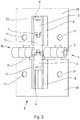
- a hinge joint 4 has been shown, which includes in its center a further pivot connection 30 and is designed as a transmission element 6. Both hinge joints 4 and 30 are not connected to each other in their joints 3 and a rotatable connection 7.
- the pivot joint 4 thus represents a transmission element 6 in the region of two abutting positionally displaceable elements 31, which are connected to one another, for example, in the horizontal direction. Covered is the upper part of the hinge joint 4 by a cover 1 and the lower part by a cover 2, wherein within the covers mounting holes 11 for attachment to the preferably plate-shaped elements 31 are present. In order not to restrict the mobility of the hinge connection 4, the covers 1 and 2 have a cutout 16.
- the pivot joint 4 consists essentially of mounting plates 28, 29, which are interconnected by the hinge 3.
- a Guide element 8 available in the middle of the Fig. 2 is respectively on the mounting plates 28 and 29 a Guide element 8 available.
- the opposing guide elements 8 on the mounting plates 28 and 29 are aligned with each other.
- the pivot joint 30 consists essentially in this preferred embodiment of a center piece 12, at the ends of each rotatable connections 7 are provided so as to connect thereto connecting elements 5 rotatable with each other. As Fig. 2 also makes clear, there is no connection between the rotatable connections 7 and the joint. 3
- the guide elements 8 are preferably laterally guides 9, in which the connecting elements 5 are mounted displaceably. This ensures that a secure sliding of the connecting elements 5 is ensured during a rotational movement of the swivel connection 4. In addition, this translational movement must also work without interference, for example when using a lock device or other connecting elements.
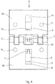
- This can in particular the Fig. 3 taken from the guide means in the form of guides 9 and a lug 10 on the connecting elements 5 is visible.
- 5 receptacles 13 are present within the connecting elements.
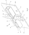
- FIG. 5 An external view of a possible embodiment with end profiles 17, 18 and with a hinge connection 4 in between gives the Fig. 5 again.
- the end profiles 17, 18 thereby form the lateral vertical terminations of the elements 31, which can be assigned to both the door and the door alike.
- the transmission element 19 is not visible to the outside.
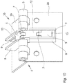
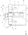
- FIG. 7 shows the transmission element 6 in a mounting situation, shows the Fig. 7 , in which the hinge joints 4 and 30 have been reproduced in a slightly pivoted representation of the end profiles 17. It is clear that the center piece 12 is not rotated with its end-side rotatable connections 7 in the same position of the center of rotation of the joint 3. This can also be shown in an enlarged, separate view of Fig. 11 be removed. Just the execution of the double-jointed rotatable connection 7 with the center piece 12 shows that even with not properly aligned transmission elements 19 a safe pivoting of the mounting plates 28, 29 is possible. This is in particular possible because the connecting elements 5 are independently displaceable in the guide elements 8, wherein a balance over the center piece 12 is achieved.
- An ideal position of the hinge joint 30 may be the Fig. 10 are removed, the independent pivot joints 4 and 30 are aligned with the joints 3 and the rotatable connection 7.
- the elements 31 can be connected one above the other in any number by transmission elements 6 tilted together.
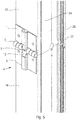
- the end profiles 17, 18 used for a door or gate or the like are have been carried out similar and are made as extruded profiles.
- the end of the side leg 24 is in the embodiment of Fig. 6 shown as final leg 25.
- a plant leg 26 is cantilevered in the opposite direction of the end leg 25.
- the plant leg 26 includes, inter alia, a seal receptacle 27, in which a seal can be pulled, in the other rooms and electrical lines can be laid.
Landscapes
- Engineering & Computer Science (AREA)
- Mechanical Engineering (AREA)
- Hinges (AREA)
- Gates (AREA)
Priority Applications (1)
| Application Number | Priority Date | Filing Date | Title |
|---|---|---|---|
| PL14186695T PL2853673T3 (pl) | 2013-09-26 | 2014-09-26 | Złącze zawiasowe i segmentowe skrzydło bramy ze złączem zawiasowym |
Applications Claiming Priority (1)
| Application Number | Priority Date | Filing Date | Title |
|---|---|---|---|
| DE102013110635.8A DE102013110635B3 (de) | 2013-09-26 | 2013-09-26 | Drehgelenkverbindung und Sektionaltorblatt mit einer Drehgelenkverbindung |
Publications (2)
| Publication Number | Publication Date |
|---|---|
| EP2853673A1 EP2853673A1 (de) | 2015-04-01 |
| EP2853673B1 true EP2853673B1 (de) | 2018-01-31 |
Family
ID=51484923
Family Applications (1)
| Application Number | Title | Priority Date | Filing Date |
|---|---|---|---|
| EP14186695.4A Active EP2853673B1 (de) | 2013-09-26 | 2014-09-26 | Drehgelenkverbindung und Sektionaltorblatt mit einer Drehgelenkverbindung |
Country Status (5)
| Country | Link |
|---|---|
| EP (1) | EP2853673B1 (pl) |
| DE (1) | DE102013110635B3 (pl) |
| DK (1) | DK2853673T3 (pl) |
| ES (1) | ES2660290T3 (pl) |
| PL (1) | PL2853673T3 (pl) |
Family Cites Families (3)
| Publication number | Priority date | Publication date | Assignee | Title |
|---|---|---|---|---|
| US5706877A (en) * | 1996-01-11 | 1998-01-13 | Overhead Door Corporation | Locking and reinforcing mechanism for garage door |
| ITUD20020021A1 (it) * | 2002-01-31 | 2003-07-31 | Breda Sistemi Ind Spa | Posizionatori per elementi per portoni a sezioni orizzontali |
| FR2889233B1 (fr) * | 2005-04-20 | 2007-10-26 | Michel Guy Rene Gelin | Serrure de portillon de porte sectionnelle |
-
2013
- 2013-09-26 DE DE102013110635.8A patent/DE102013110635B3/de active Active
-
2014
- 2014-09-26 ES ES14186695.4T patent/ES2660290T3/es active Active
- 2014-09-26 DK DK14186695.4T patent/DK2853673T3/en active
- 2014-09-26 EP EP14186695.4A patent/EP2853673B1/de active Active
- 2014-09-26 PL PL14186695T patent/PL2853673T3/pl unknown
Non-Patent Citations (1)
| Title |
|---|
| None * |
Also Published As
| Publication number | Publication date |
|---|---|
| PL2853673T3 (pl) | 2018-07-31 |
| ES2660290T3 (es) | 2018-03-21 |
| DK2853673T3 (en) | 2018-05-07 |
| DE102013110635B3 (de) | 2014-09-25 |
| EP2853673A1 (de) | 2015-04-01 |
Similar Documents
| Publication | Publication Date | Title |
|---|---|---|
| DE10053433C2 (de) | Schrank, insbesondere Geräteschrank | |
| DE102011011113B4 (de) | Rahmensystem eines Partikelschutzgitters | |
| AT510570B1 (de) | Einrichtung zum verschliessen einer öffnung | |
| DE102016111564A1 (de) | Stangenschloss | |
| EP2721236B1 (de) | Innenliegendes 180-grad-scharnier für eine reihenschrankanordnung | |
| DE102010038084A1 (de) | Schiebedrehwandsystem | |
| WO2019101260A1 (de) | Schliesseinrichtung für einen schaltschrank und ein entsprechender schaltschrank | |
| EP1568833B1 (de) | Schliessblech für ein Fenster oder eine Tür | |
| DE10117173A9 (de) | Tuer | |
| DE3110110C1 (de) | Duschabtrennung | |
| EP2853673B1 (de) | Drehgelenkverbindung und Sektionaltorblatt mit einer Drehgelenkverbindung | |
| EP2453097B1 (de) | Seitensektionaltor mit Verriegelungseinrichtung | |
| DE3938116C2 (pl) | ||
| DE102014226794A1 (de) | Beschlag zum Einbau zwischen einem Flügel und einem festen Rahmen eines Fensters, einer Tür oder dergleichen sowie Fenster, Tür oder dergleichen mit einem derartigen Beschlag | |
| DE10316284A1 (de) | Tor | |
| DE102019209409A1 (de) | Abdeckhaube für einen tür- oder fensterantrieb | |
| EP4215704B1 (de) | Sperrvorrichtung, beschlag und flügel-rahmenanordnung | |
| DE19603415C1 (de) | Vorrichtung zur Verriegelung eines zwischen zwei Endstellungen um eine Achse schwenkbaren, in Verschlußstellung befindlichen Bauteils zum Verschließen einer Zugangsöffnung zu einem von Wänden umschlossenen Raum | |
| DE102014111131A1 (de) | Vorrichtung zur Ver- und Entriegelung eines Fensterflügels, einer Lüftungsklappe oder dergleichen an einem Blendrahmen | |
| DE4336203A1 (de) | Schaltschrank mit einem Rahmengestell aus Rahmenschenkeln | |
| DE19603417C1 (de) | Vorrichtung zur Sicherung eines zwischen zwei Endstellungen bewegbaren Bauteils zum Verschließen einer Wandöffnung eines Gebäudes | |
| DE29818045U1 (de) | Beschlag für Klappfenster, insbesondere von Wohnwagen, Mobilheimen u.dgl. | |
| DE10147990A1 (de) | Schaltschrank | |
| DE10301046A1 (de) | Drehbeschlag für die verdeckte Anordnung an Türen oder Fenstern | |
| DE29817840U1 (de) | Schaltschrank mit Stangenverschluß |
Legal Events
| Date | Code | Title | Description |
|---|---|---|---|
| PUAI | Public reference made under article 153(3) epc to a published international application that has entered the european phase |
Free format text: ORIGINAL CODE: 0009012 |
|
| 17P | Request for examination filed |
Effective date: 20140926 |
|
| AK | Designated contracting states |
Kind code of ref document: A1 Designated state(s): AL AT BE BG CH CY CZ DE DK EE ES FI FR GB GR HR HU IE IS IT LI LT LU LV MC MK MT NL NO PL PT RO RS SE SI SK SM TR |
|
| AX | Request for extension of the european patent |
Extension state: BA ME |
|
| R17P | Request for examination filed (corrected) |
Effective date: 20150929 |
|
| RBV | Designated contracting states (corrected) |
Designated state(s): AL AT BE BG CH CY CZ DE DK EE ES FI FR GB GR HR HU IE IS IT LI LT LU LV MC MK MT NL NO PL PT RO RS SE SI SK SM TR |
|
| RIC1 | Information provided on ipc code assigned before grant |
Ipc: E05D 15/24 20060101ALI20170807BHEP Ipc: E06B 3/48 20060101AFI20170807BHEP Ipc: E05D 3/10 20060101ALI20170807BHEP Ipc: E06B 3/70 20060101ALI20170807BHEP Ipc: E05D 3/18 20060101ALI20170807BHEP |
|
| GRAP | Despatch of communication of intention to grant a patent |
Free format text: ORIGINAL CODE: EPIDOSNIGR1 |
|
| STAA | Information on the status of an ep patent application or granted ep patent |
Free format text: STATUS: GRANT OF PATENT IS INTENDED |
|
| INTG | Intention to grant announced |
Effective date: 20170928 |
|
| GRAS | Grant fee paid |
Free format text: ORIGINAL CODE: EPIDOSNIGR3 |
|
| GRAA | (expected) grant |
Free format text: ORIGINAL CODE: 0009210 |
|
| STAA | Information on the status of an ep patent application or granted ep patent |
Free format text: STATUS: THE PATENT HAS BEEN GRANTED |
|
| AK | Designated contracting states |
Kind code of ref document: B1 Designated state(s): AL AT BE BG CH CY CZ DE DK EE ES FI FR GB GR HR HU IE IS IT LI LT LU LV MC MK MT NL NO PL PT RO RS SE SI SK SM TR |
|
| REG | Reference to a national code |
Ref country code: GB Ref legal event code: FG4D Free format text: NOT ENGLISH Ref country code: CH Ref legal event code: EP |
|
| REG | Reference to a national code |
Ref country code: SE Ref legal event code: TRGR |
|
| REG | Reference to a national code |
Ref country code: AT Ref legal event code: REF Ref document number: 967564 Country of ref document: AT Kind code of ref document: T Effective date: 20180215 |
|
| REG | Reference to a national code |
Ref country code: IE Ref legal event code: FG4D Free format text: LANGUAGE OF EP DOCUMENT: GERMAN |
|
| REG | Reference to a national code |
Ref country code: DE Ref legal event code: R096 Ref document number: 502014007082 Country of ref document: DE |
|
| REG | Reference to a national code |
Ref country code: ES Ref legal event code: FG2A Ref document number: 2660290 Country of ref document: ES Kind code of ref document: T3 Effective date: 20180321 |
|
| REG | Reference to a national code |
Ref country code: NL Ref legal event code: FP |
|
| REG | Reference to a national code |
Ref country code: DK Ref legal event code: T3 Effective date: 20180503 |
|
| REG | Reference to a national code |
Ref country code: LT Ref legal event code: MG4D |
|
| PG25 | Lapsed in a contracting state [announced via postgrant information from national office to epo] |
Ref country code: FI Free format text: LAPSE BECAUSE OF FAILURE TO SUBMIT A TRANSLATION OF THE DESCRIPTION OR TO PAY THE FEE WITHIN THE PRESCRIBED TIME-LIMIT Effective date: 20180131 Ref country code: HR Free format text: LAPSE BECAUSE OF FAILURE TO SUBMIT A TRANSLATION OF THE DESCRIPTION OR TO PAY THE FEE WITHIN THE PRESCRIBED TIME-LIMIT Effective date: 20180131 Ref country code: LT Free format text: LAPSE BECAUSE OF FAILURE TO SUBMIT A TRANSLATION OF THE DESCRIPTION OR TO PAY THE FEE WITHIN THE PRESCRIBED TIME-LIMIT Effective date: 20180131 Ref country code: NO Free format text: LAPSE BECAUSE OF FAILURE TO SUBMIT A TRANSLATION OF THE DESCRIPTION OR TO PAY THE FEE WITHIN THE PRESCRIBED TIME-LIMIT Effective date: 20180430 |
|
| PG25 | Lapsed in a contracting state [announced via postgrant information from national office to epo] |
Ref country code: GR Free format text: LAPSE BECAUSE OF FAILURE TO SUBMIT A TRANSLATION OF THE DESCRIPTION OR TO PAY THE FEE WITHIN THE PRESCRIBED TIME-LIMIT Effective date: 20180501 Ref country code: RS Free format text: LAPSE BECAUSE OF FAILURE TO SUBMIT A TRANSLATION OF THE DESCRIPTION OR TO PAY THE FEE WITHIN THE PRESCRIBED TIME-LIMIT Effective date: 20180131 Ref country code: LV Free format text: LAPSE BECAUSE OF FAILURE TO SUBMIT A TRANSLATION OF THE DESCRIPTION OR TO PAY THE FEE WITHIN THE PRESCRIBED TIME-LIMIT Effective date: 20180131 Ref country code: IS Free format text: LAPSE BECAUSE OF FAILURE TO SUBMIT A TRANSLATION OF THE DESCRIPTION OR TO PAY THE FEE WITHIN THE PRESCRIBED TIME-LIMIT Effective date: 20180531 Ref country code: BG Free format text: LAPSE BECAUSE OF FAILURE TO SUBMIT A TRANSLATION OF THE DESCRIPTION OR TO PAY THE FEE WITHIN THE PRESCRIBED TIME-LIMIT Effective date: 20180430 |
|
| REG | Reference to a national code |
Ref country code: FR Ref legal event code: PLFP Year of fee payment: 5 |
|
| PG25 | Lapsed in a contracting state [announced via postgrant information from national office to epo] |
Ref country code: MT Free format text: LAPSE BECAUSE OF FAILURE TO SUBMIT A TRANSLATION OF THE DESCRIPTION OR TO PAY THE FEE WITHIN THE PRESCRIBED TIME-LIMIT Effective date: 20180131 |
|
| PG25 | Lapsed in a contracting state [announced via postgrant information from national office to epo] |
Ref country code: AL Free format text: LAPSE BECAUSE OF FAILURE TO SUBMIT A TRANSLATION OF THE DESCRIPTION OR TO PAY THE FEE WITHIN THE PRESCRIBED TIME-LIMIT Effective date: 20180131 Ref country code: EE Free format text: LAPSE BECAUSE OF FAILURE TO SUBMIT A TRANSLATION OF THE DESCRIPTION OR TO PAY THE FEE WITHIN THE PRESCRIBED TIME-LIMIT Effective date: 20180131 Ref country code: IT Free format text: LAPSE BECAUSE OF FAILURE TO SUBMIT A TRANSLATION OF THE DESCRIPTION OR TO PAY THE FEE WITHIN THE PRESCRIBED TIME-LIMIT Effective date: 20180131 Ref country code: RO Free format text: LAPSE BECAUSE OF FAILURE TO SUBMIT A TRANSLATION OF THE DESCRIPTION OR TO PAY THE FEE WITHIN THE PRESCRIBED TIME-LIMIT Effective date: 20180131 |
|
| REG | Reference to a national code |
Ref country code: DE Ref legal event code: R097 Ref document number: 502014007082 Country of ref document: DE |
|
| PG25 | Lapsed in a contracting state [announced via postgrant information from national office to epo] |
Ref country code: CZ Free format text: LAPSE BECAUSE OF FAILURE TO SUBMIT A TRANSLATION OF THE DESCRIPTION OR TO PAY THE FEE WITHIN THE PRESCRIBED TIME-LIMIT Effective date: 20180131 Ref country code: SK Free format text: LAPSE BECAUSE OF FAILURE TO SUBMIT A TRANSLATION OF THE DESCRIPTION OR TO PAY THE FEE WITHIN THE PRESCRIBED TIME-LIMIT Effective date: 20180131 Ref country code: SM Free format text: LAPSE BECAUSE OF FAILURE TO SUBMIT A TRANSLATION OF THE DESCRIPTION OR TO PAY THE FEE WITHIN THE PRESCRIBED TIME-LIMIT Effective date: 20180131 |
|
| PLBE | No opposition filed within time limit |
Free format text: ORIGINAL CODE: 0009261 |
|
| STAA | Information on the status of an ep patent application or granted ep patent |
Free format text: STATUS: NO OPPOSITION FILED WITHIN TIME LIMIT |
|
| 26N | No opposition filed |
Effective date: 20181102 |
|
| PG25 | Lapsed in a contracting state [announced via postgrant information from national office to epo] |
Ref country code: SI Free format text: LAPSE BECAUSE OF FAILURE TO SUBMIT A TRANSLATION OF THE DESCRIPTION OR TO PAY THE FEE WITHIN THE PRESCRIBED TIME-LIMIT Effective date: 20180131 |
|
| PG25 | Lapsed in a contracting state [announced via postgrant information from national office to epo] |
Ref country code: MC Free format text: LAPSE BECAUSE OF FAILURE TO SUBMIT A TRANSLATION OF THE DESCRIPTION OR TO PAY THE FEE WITHIN THE PRESCRIBED TIME-LIMIT Effective date: 20180131 |
|
| REG | Reference to a national code |
Ref country code: CH Ref legal event code: PL |
|
| REG | Reference to a national code |
Ref country code: IE Ref legal event code: MM4A |
|
| PG25 | Lapsed in a contracting state [announced via postgrant information from national office to epo] |
Ref country code: LU Free format text: LAPSE BECAUSE OF NON-PAYMENT OF DUE FEES Effective date: 20180926 |
|
| PG25 | Lapsed in a contracting state [announced via postgrant information from national office to epo] |
Ref country code: IE Free format text: LAPSE BECAUSE OF NON-PAYMENT OF DUE FEES Effective date: 20180926 |
|
| PG25 | Lapsed in a contracting state [announced via postgrant information from national office to epo] |
Ref country code: LI Free format text: LAPSE BECAUSE OF NON-PAYMENT OF DUE FEES Effective date: 20180930 Ref country code: CH Free format text: LAPSE BECAUSE OF NON-PAYMENT OF DUE FEES Effective date: 20180930 |
|
| PG25 | Lapsed in a contracting state [announced via postgrant information from national office to epo] |
Ref country code: TR Free format text: LAPSE BECAUSE OF FAILURE TO SUBMIT A TRANSLATION OF THE DESCRIPTION OR TO PAY THE FEE WITHIN THE PRESCRIBED TIME-LIMIT Effective date: 20180131 |
|
| PG25 | Lapsed in a contracting state [announced via postgrant information from national office to epo] |
Ref country code: HU Free format text: LAPSE BECAUSE OF FAILURE TO SUBMIT A TRANSLATION OF THE DESCRIPTION OR TO PAY THE FEE WITHIN THE PRESCRIBED TIME-LIMIT; INVALID AB INITIO Effective date: 20140926 Ref country code: PT Free format text: LAPSE BECAUSE OF FAILURE TO SUBMIT A TRANSLATION OF THE DESCRIPTION OR TO PAY THE FEE WITHIN THE PRESCRIBED TIME-LIMIT Effective date: 20180131 |
|
| PG25 | Lapsed in a contracting state [announced via postgrant information from national office to epo] |
Ref country code: CY Free format text: LAPSE BECAUSE OF FAILURE TO SUBMIT A TRANSLATION OF THE DESCRIPTION OR TO PAY THE FEE WITHIN THE PRESCRIBED TIME-LIMIT Effective date: 20180131 Ref country code: MK Free format text: LAPSE BECAUSE OF NON-PAYMENT OF DUE FEES Effective date: 20180131 |
|
| REG | Reference to a national code |
Ref country code: AT Ref legal event code: MM01 Ref document number: 967564 Country of ref document: AT Kind code of ref document: T Effective date: 20190926 |
|
| PG25 | Lapsed in a contracting state [announced via postgrant information from national office to epo] |
Ref country code: AT Free format text: LAPSE BECAUSE OF NON-PAYMENT OF DUE FEES Effective date: 20190926 |
|
| PGFP | Annual fee paid to national office [announced via postgrant information from national office to epo] |
Ref country code: DK Payment date: 20250923 Year of fee payment: 12 Ref country code: DE Payment date: 20250919 Year of fee payment: 12 |
|
| PGFP | Annual fee paid to national office [announced via postgrant information from national office to epo] |
Ref country code: NL Payment date: 20250918 Year of fee payment: 12 Ref country code: PL Payment date: 20250918 Year of fee payment: 12 |
|
| PGFP | Annual fee paid to national office [announced via postgrant information from national office to epo] |
Ref country code: GB Payment date: 20250918 Year of fee payment: 12 Ref country code: BE Payment date: 20250918 Year of fee payment: 12 |
|
| PGFP | Annual fee paid to national office [announced via postgrant information from national office to epo] |
Ref country code: FR Payment date: 20250922 Year of fee payment: 12 |
|
| PGFP | Annual fee paid to national office [announced via postgrant information from national office to epo] |
Ref country code: SE Payment date: 20250918 Year of fee payment: 12 |
|
| PGFP | Annual fee paid to national office [announced via postgrant information from national office to epo] |
Ref country code: ES Payment date: 20251028 Year of fee payment: 12 |