EP2853654A2 - Konsole und Fassadenunterkonstruktion mit der Konsole - Google Patents
Konsole und Fassadenunterkonstruktion mit der Konsole Download PDFInfo
- Publication number
- EP2853654A2 EP2853654A2 EP20140178089 EP14178089A EP2853654A2 EP 2853654 A2 EP2853654 A2 EP 2853654A2 EP 20140178089 EP20140178089 EP 20140178089 EP 14178089 A EP14178089 A EP 14178089A EP 2853654 A2 EP2853654 A2 EP 2853654A2
- Authority
- EP
- European Patent Office
- Prior art keywords
- rod
- console
- connecting part
- building wall
- attachment
- Prior art date
- Legal status (The legal status is an assumption and is not a legal conclusion. Google has not performed a legal analysis and makes no representation as to the accuracy of the status listed.)
- Granted
Links
- 239000000835 fiber Substances 0.000 claims abstract description 35
- 230000037431 insertion Effects 0.000 claims abstract description 21
- 238000003780 insertion Methods 0.000 claims abstract description 21
- 230000002787 reinforcement Effects 0.000 claims abstract description 11
- 238000004873 anchoring Methods 0.000 claims abstract description 6
- 239000004570 mortar (masonry) Substances 0.000 claims description 31
- 239000004033 plastic Substances 0.000 claims description 13
- 229920003023 plastic Polymers 0.000 claims description 13
- 239000000853 adhesive Substances 0.000 claims description 6
- 230000001070 adhesive effect Effects 0.000 claims description 6
- 239000011159 matrix material Substances 0.000 claims description 5
- 239000002131 composite material Substances 0.000 abstract description 10
- 239000004744 fabric Substances 0.000 abstract description 2
- 238000009413 insulation Methods 0.000 description 14
- 238000004519 manufacturing process Methods 0.000 description 9
- 125000006850 spacer group Chemical group 0.000 description 7
- 210000002414 leg Anatomy 0.000 description 6
- 238000010276 construction Methods 0.000 description 5
- 229920005989 resin Polymers 0.000 description 5
- 239000011347 resin Substances 0.000 description 5
- 229910052751 metal Inorganic materials 0.000 description 4
- 239000002184 metal Substances 0.000 description 4
- 229910052782 aluminium Inorganic materials 0.000 description 3
- XAGFODPZIPBFFR-UHFFFAOYSA-N aluminium Chemical compound [Al] XAGFODPZIPBFFR-UHFFFAOYSA-N 0.000 description 3
- 239000004567 concrete Substances 0.000 description 3
- 230000007423 decrease Effects 0.000 description 3
- 229920000049 Carbon (fiber) Polymers 0.000 description 2
- 239000004743 Polypropylene Substances 0.000 description 2
- 239000004917 carbon fiber Substances 0.000 description 2
- 238000005253 cladding Methods 0.000 description 2
- 238000002347 injection Methods 0.000 description 2
- 239000007924 injection Substances 0.000 description 2
- 238000009434 installation Methods 0.000 description 2
- 239000000463 material Substances 0.000 description 2
- -1 polypropylene Polymers 0.000 description 2
- 229920001155 polypropylene Polymers 0.000 description 2
- 238000009418 renovation Methods 0.000 description 2
- 239000000126 substance Substances 0.000 description 2
- 229920002430 Fibre-reinforced plastic Polymers 0.000 description 1
- 240000006829 Ficus sundaica Species 0.000 description 1
- 239000004952 Polyamide Substances 0.000 description 1
- 239000004793 Polystyrene Substances 0.000 description 1
- 230000006978 adaptation Effects 0.000 description 1
- 238000004026 adhesive bonding Methods 0.000 description 1
- 239000004760 aramid Substances 0.000 description 1
- 229920006231 aramid fiber Polymers 0.000 description 1
- 238000005452 bending Methods 0.000 description 1
- 230000015572 biosynthetic process Effects 0.000 description 1
- 239000011449 brick Substances 0.000 description 1
- 239000011083 cement mortar Substances 0.000 description 1
- 150000001875 compounds Chemical class 0.000 description 1
- 239000004035 construction material Substances 0.000 description 1
- 238000005520 cutting process Methods 0.000 description 1
- 239000011151 fibre-reinforced plastic Substances 0.000 description 1
- 239000011152 fibreglass Substances 0.000 description 1
- 238000005187 foaming Methods 0.000 description 1
- 239000003365 glass fiber Substances 0.000 description 1
- 230000005484 gravity Effects 0.000 description 1
- 238000007654 immersion Methods 0.000 description 1
- VNWKTOKETHGBQD-UHFFFAOYSA-N methane Chemical compound C VNWKTOKETHGBQD-UHFFFAOYSA-N 0.000 description 1
- 239000000203 mixture Substances 0.000 description 1
- 238000005192 partition Methods 0.000 description 1
- 229920002647 polyamide Polymers 0.000 description 1
- 229920000515 polycarbonate Polymers 0.000 description 1
- 239000004417 polycarbonate Substances 0.000 description 1
- 229920002223 polystyrene Polymers 0.000 description 1
- 239000007787 solid Substances 0.000 description 1
- 230000003068 static effect Effects 0.000 description 1
- 229920003002 synthetic resin Polymers 0.000 description 1
- 239000000057 synthetic resin Substances 0.000 description 1
- 230000007704 transition Effects 0.000 description 1
- 210000000689 upper leg Anatomy 0.000 description 1
- 239000002023 wood Substances 0.000 description 1
Images


Classifications
-
- E—FIXED CONSTRUCTIONS
- E04—BUILDING
- E04F—FINISHING WORK ON BUILDINGS, e.g. STAIRS, FLOORS
- E04F13/00—Coverings or linings, e.g. for walls or ceilings
- E04F13/07—Coverings or linings, e.g. for walls or ceilings composed of covering or lining elements; Sub-structures therefor; Fastening means therefor
- E04F13/08—Coverings or linings, e.g. for walls or ceilings composed of covering or lining elements; Sub-structures therefor; Fastening means therefor composed of a plurality of similar covering or lining elements
- E04F13/0801—Separate fastening elements
- E04F13/0803—Separate fastening elements with load-supporting elongated furring elements between wall and covering elements
- E04F13/0805—Separate fastening elements with load-supporting elongated furring elements between wall and covering elements with additional fastening elements between furring elements and the wall
- E04F13/0807—Separate fastening elements with load-supporting elongated furring elements between wall and covering elements with additional fastening elements between furring elements and the wall adjustable perpendicular to the wall
-
- F—MECHANICAL ENGINEERING; LIGHTING; HEATING; WEAPONS; BLASTING
- F16—ENGINEERING ELEMENTS AND UNITS; GENERAL MEASURES FOR PRODUCING AND MAINTAINING EFFECTIVE FUNCTIONING OF MACHINES OR INSTALLATIONS; THERMAL INSULATION IN GENERAL
- F16B—DEVICES FOR FASTENING OR SECURING CONSTRUCTIONAL ELEMENTS OR MACHINE PARTS TOGETHER, e.g. NAILS, BOLTS, CIRCLIPS, CLAMPS, CLIPS OR WEDGES; JOINTS OR JOINTING
- F16B13/00—Dowels or other devices fastened in walls or the like by inserting them in holes made therein for that purpose
- F16B13/14—Non-metallic plugs or sleeves; Use of liquid, loose solid or kneadable material therefor
- F16B13/141—Fixing plugs in holes by the use of settable material
- F16B13/143—Fixing plugs in holes by the use of settable material using frangible cartridges or capsules containing the setting components
Definitions
- the present invention relates to a console according to the preamble of claim 1 and a facade substructure according to claim 14
- the publication DE-OS-100 10 473 A1 describes a composite anchor for materially retaining a fastener in a borehole.
- the composite anchor has a cartridge comprising one or more chambers in which a foaming substance or the components of a multi-component resin are accommodated.
- the chambers are designed so that they are destroyed when screwing a fastening screw.
- the injection cartridge can be accommodated in the shaft of a plastic anchor which at least partially surrounds the cartridge.
- the Canadian patent CA-2 226 584 discloses a connecting part 1,2 with a first and a second head piece 1, which end pieces are connected to each other with a spacer member, which bridges the space between the supporting structure and a cladding substantially.
- the spacer is formed substantially plate-shaped and consists of a plastic construction material.
- fastening passages (s. FIG. 6 ) provided by which a mechanical attachment between the end pieces and the spacer member can be produced. This mechanical attachment can be produced by fastening means in the fastening passages.
- German utility model DE-U-20 2007 009 780 discloses a designated as a mounting bracket connecting part, which is the attachment of a Facade on a supporting structure is used. It has a first and a second head piece (Konsolenfuss 2 and opposite end piece), which are interconnected by a plate-shaped spacer 4 (console web).
- the spacer consists of a glass fiber reinforced plastic, which bridges the space between the structure and the facade.
- the patent AT-A-511 443 discloses a means for attaching a load to a wall provided with at least one insulating layer.
- the device comprises a sleeve with a receiving channel for a fastening bolt or a fastening screw. Protruding from the outside of the sleeve at least two in the axial direction of the sleeve extending support ribs, at least one of which protrudes further from the sleeve than the other.
- the sleeve is preferably made of plastic or a composite material, in particular a fiber-reinforced plastic.
- the length of the sleeve is adapted to the thickness of the insulating layer.
- the fixing screw which is inserted during installation in the receiving channel and anchored by means of a dowel in a concrete or brick wall, however, is a conventional metal screw, so that still exists a thermal bridge.
- the French patent with the number FR 2 950 637 discloses an insulated wall of individual wall elements held together by mortar or adhesive, insulation and trim. A part of the wall elements has preformed holes for receiving fasteners for fixing the insulation and the cladding.
- the fasteners may be made of plastic or metal. As far as can be seen in the figures, the fastening elements can be suspended in the preformed holes of the wall elements.
- the fasteners have for this purpose on the front end of a groove.
- a fastener for spacing mounting ledges to a vertical wall comprising a screw having one end configured for attachment to the wall and the other end threaded.
- a strip holder is fastened by means of a counter thread having a component, wherein the strip holder relative to the component is freely rotatable.
- the screw of the fastener consists of a bolt and a sleeve which rest on the rear, protruding from the wall section of the Bolzens is postponed.
- the bolt has a front bolt portion which is formed like a wood screw and a threaded au utilizat which can be screwed into a dowel. According to the EP-A-1 203 853 the thermal decoupling is achieved only by the dowel, but not with the fastener itself.
- Object of the present invention is therefore to propose a console and a facade substructure with the console, which largely eliminate the problem of thermal bridges.
- a goal is to propose a console, which can also be used for the subsequent renovation of already insulated facade walls.
- the console should be adaptable to different thicknesses without significantly increasing their production costs.
- Another goal is to propose a facade substructure, which can be realized with less effort than conventional facade substructures.
- the invention relates to a console for the attachment of facade elements on a building wall.
- This console which can also be referred to as facade anchors, has a front insertion for anchoring in a building wall and a rear header with a mounting option for the attachment of facade elements.
- the inventive console is characterized by the fact that the inserted rod is made of plastic, in which a fiber reinforcement, preferably of continuous fibers, is embedded.
- the front insertion end which serves for anchoring in a wall, has at least one diameter-reduced intermediate section.
- the fiber reinforcement may by a preferred predominantly unidirectional fiber fabric or by substantially longitudinally aligned roving strands resp. Endlosmaschinen be formed.
- This console has the advantage that it can be used even with already provided with an insulation walls, as they have no foot piece.
- the bar of the console can be anchored directly in a borehole in the housing wall. Because the rod has a fiber reinforcement with mostly longitudinally oriented fibers, the load capacity of the console is extremely high. Due to the tapered intermediate section, the pull-out force can be increased to such an extent that the console can withstand even large wind loads.
- a rod is to be understood as meaning an elongate, cylindrical part whose length is at least 10 times longer than its thickness and whose width is at most 8 times greater than its thickness.
- the thickness is at least an order of magnitude smaller than the other two dimensions, and the plate is basically flat.
- a "borehole” within the meaning of the invention is generally to be understood as a hole independent of its production.
- the front end of the rod is formed as a conical or wedge tip and immediately thereafter followed by the tapered intermediate section.
- the rod can be easily inserted into a borehole, even if it lies under an insulating layer.
- the displaced mortar can then fill the space released by the tapered intermediate section and then provide a high pull-out strength of the bar after curing.
- the fiber reinforcement of the rod is advantageously made of fibers arranged in the longitudinal direction, in particular continuous fibers such as roving strands or filament fibers, produced.
- continuous fibers which in the majority have essentially the length of the rod, the flexural strength and thus the load capacity of the console are very high.
- the fiber reinforcement can be inserted, for example, as a unidirectional scrim in an injection mold and then encapsulated with a suitable, forming the matrix plastic.
- the length of the continuous fibers used preferably corresponds to at least 60%, more preferably at least 80% and most preferably at least 90% of the length of the rod and is at least 20 mm, preferably at least 30 mm and particularly preferably at least 50 mm long.
- the continuous fibers are oriented substantially in the direction of the tensile and compressive forces which occur when the rod is bent.
- the tensile forces can therefore be optimally absorbed by the fibers.
- the plastic matrix may also contain a proportion of short cut fibers.
- Preferred plastics for the production of the rod are polyamide, polycarbonate, or polystyrene, and more preferably polypropylene, since polypropylene has a low specific gravity and is inexpensive to manufacture.
- the rod can be basically round, 3, 4, 5, 6-square or even polygonal in cross-section.
- the rod has radially projecting, axially extending ribs.
- the ribs By the ribs, the rigidity of the rod can be further improved.
- the rib height is 0.05 to 0.5 times the rod radius, preferably 0.1 to 0.4 times the rod radius, and more preferably 0.2 to 0.3 times the rod radius.
- the ribs may have a different cross section.
- the cross section of the ribs is trapezoidal or triangular.
- the rod has a star shape in cross section, i. a total of 4.5, 6 or more ribs are formed on the circumference. Such a construction has proven itself in practice for reasons of symmetry.
- the rod of the console can be well inserted into a borehole.
- the longitudinal ribs which are also present in the area of the tip, the mortar can be well displaced in the well, so that the rod can be easily inserted.
- the largest diameter of the insertion end is 0.5 to 4, preferably 1 to 3 mm smaller than the largest diameter of the rod. This has the advantage that an adhesive cartridge can be placed on the front end, without the diameter of the projecting from the building wall rod would thereby exceeded.
- the head piece is attached to the mounting possibility on the rod and preferably placed on this. This has the advantage that different fastening devices or supporting parts can be attached to the rod.
- the head piece with the mounting option is made in two parts and has a connection part and a connecting part.
- the attachment part designed as a connecting part is attached to the rod end, and the connecting part is attached to the connecting part, respectively. fixable.
- a plurality of spaced-apart connecting positions are defined on the connecting part and the connecting part in the longitudinal direction.
- This has the great advantage that the effective length of the entire console for a given length of the composite plastic rod in a certain range is variable. This makes it possible to cover with 3 or 4 different basic lengths of the composite plastic rod all the insulation thicknesses encountered in today's house building.
- the connection part and possibly also the Connecting part can be produced inexpensively, for example, as extruded aluminum profile.
- a longitudinal guide is formed between the connecting part and the connecting part. This has the advantage that connecting part and connecting part are encompassed transversely to the longitudinal axis of the rod positively, and a high stability of the console is ensured.
- the connecting part has a connecting portion, which serves for connection to the connecting part, and a fastening portion, on which a profile rail can be fastened.
- the connecting portion has a greater extent in the direction of the longitudinal axis than the connecting part. This makes it possible to adjust the effective length of the console in a certain range by attaching the connecting portion closer or farther away from the front end of the rod to the connecting part. This adaptation can be made on the construction site without any problems.
- a slot is provided, in which a profile rail can be received and fastened.
- the provision of a slot has the advantage that an adjustment in a certain length range is possible by the rail is inserted different distances in the insertion slot. With the Justierönkeit described can be unevenness of a building wall compensate.
- the connecting part has a fastening section serving as a cantilever arm with at least one fastening passage.
- a fastening passage can serve a closed or semi-open channel, in which a screw can be screwed.
- a mortar-containing cartridge is applied to the front end of the rod.
- mortar is to be understood as meaning any hardening mass, whether composed of one, two or even more components.
- the cartridge is usually formed as a hollow cylinder whose front end is closed by a bottom and the rear end has an opening. Through the opening a container filled with a mortar mass in the cartridge be. It is conceivable that the mortar mass is separated by means of only a partition from the environment. Depending on the application, a 2-component resin can also be used. In this case two separate containers are necessary. These can be nested or executed as a double-walled container.
- the cartridge may thus have an outer container and an inner container, wherein in the space between the outer and the inner container, the one resin component and the inner container, the second resin component is added. It is also conceivable that the mortar cartridge is detached from the console first introduced into the wellbore.
- console system comprising a console according to the invention and a mortar cartridge.
- console and mortar cartridge can be used as separate units, i. in the console system, the mortar cartridge can first be inserted into the wellbore and then the rod of the console inserted into the cartridge.
- the front end of the rod is adhesively bonded to the support structure by means of an adhesive or mortar.
- the rod can be set with sleeve and adhesive mortar or be mounted directly in concrete, masonry or other solid surface with mortar.
- a longitudinal guide is provided between the connecting part and the connecting part.
- the longitudinal guide provides a great stability transverse to the longitudinal axis of the rod, even if the head piece is made of two parts.
- the connection part and connecting part can be moved relative to each other. The relative longitudinal displaceability of the parts can be increased by the connecting portion of the connecting part seen in the axial direction is longer than the connecting part.
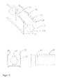
- FIGS. 1 and 2 show a console 11 according to the invention with a rod 17 with a front insertion end 13, which is intended for inclusion in a borehole in a building wall and arranged at the opposite end of the rod head piece 15 for attachment of rails, on which the facade elements can be arranged. It is also conceivable that the facade elements are attached directly to the head piece 15.
- the insertion end 13 is offset from the shaft 17 by means of a tapered portion 19, which has a smaller diameter than the remaining rod 17 and the thickest point 21 of the front end portion 13.
- the transition between the tapered portion 19 and the shaft 17 forms an annular shoulder 25. From the annular shoulder 25 in the direction of the tip 27, the diameter of the rod increases continuously until it reaches the largest diameter at the point 21.
- the diameter decreases continuously up to the tip 27 and thereby defines a wedge or conical tip 23.
- Continuous feed resp. Decrease should be a uniform or uneven supply resp. Decrease be understood, so that the corresponding contours are linear or arcuate in longitudinal section.
- the rod 17 is made of a fiber composite material.
- the fiber composite material consists of a matrix and arranged therein fiber reinforcement of longitudinally arranged (continuous) fibers, in particular roving strands or filament fibers. But also long fibers or unidirectional scrims arranged in the longitudinal direction of the rod can be used as fibers.
- the matrix of the composite is formed from a suitable plastic.
- the diameter at the point 21 may be slightly smaller than the rear shaft diameter, so that - as will be explained below - a mortar cartridge can be plugged onto the insertion end 13.
- the rod 17 has on the circumference in the axial direction 28 ( Fig. 1 ) extending longitudinal ribs 29 formed with a substantially triangular cross-section. This gives the rod in cross-section a star shape.
- longitudinal ribs 29 results in an enlargement of the lateral surface, so that when a bonding of the front end portion in a borehole results in a higher pull-out force.
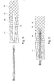
- connection part 31 is arranged, which in the FIG. 3 is shown in more detail in detail.
- the connecting part 31 can be fastened to the shaft of the rod 17 by means of suitable fastening means, such as, for example, screws or rivets. It is also conceivable, however, that the connecting part is connected to the rod cohesively by means of an adhesive.
- a hollow cylindrical receptacle 37 in which the rear end of the shaft is positively inserted and fastened or fastened in this position.
- the connecting part 31 is according to the illustrated embodiment, a cuboid metal block 33, preferably made of aluminum, in which a the outer profile of the shaft corresponding receptacle 37 is formed in the form of a channel.
- An im Terminal part 31 provided passage opening 41 serves to receive a screw or rivet 38 for fixing the same on the shaft 17 (s. FIGS. 5 and 6 ).
- the connecting part 31 is used to attach a connecting part 35 which is longitudinally displaceably guided on the connecting part 31 and can be fastened in different positions.
- This has the great advantage that the total length of the console during production can be varied within a certain range.
- a parallel to the rod axis 28 extending longitudinal guide is provided between the connecting part 31 and the connecting part 35.
- This longitudinal guide is realized in the illustrated embodiment by two lateral strips 39 which are formed on two opposite flat sides of the connecting part 31 and in which a U-shaped head piece 43 of the connecting part 35 can engage.
- the U-shaped head piece 43 has two legs 45 a, 45 b, which find space between the strips 39 of the connecting part 31.
- one or more holes 47a, 47b are respectively provided in correspondence with the through hole 41 of the fitting part 31, which holes can be made to coincide with the through hole 41 for connection with the fitting part 31. If a plurality of holes 47a, 47b are provided in the longitudinal direction of the connecting part 35, the length of the console can still be adapted during production.
- the connecting part 35 has a connecting portion 48 for connection to the connecting part 31 and a fixing portion 49 for fixing a rail or a facade element.
- the attachment portion 49 has a slot 51 which is adapted to receive a flat fastener, e.g. the leg of a T-rail, serves.
- the inserted fastener is fixed by means of a screw 53, which in a channel 55 which extends at right angles to the longitudinal axis of the rod, can be screwed.
- a cartridge 59 partially filled with a mortar 57 is provided, which can be plugged onto the insertion end 13 (FIG. Figures 1 and 2 ).
- the mortar can be filled from the factory in the cartridge 59 and the cartridge is then closed at its opening 63 with a lid so that the mortar does not dry. The lid is either removed prior to assembly or punctured by the rod tip 27 when setting the rod 17. It is also conceivable that the mortar is filled only shortly before mounting the console 11 in the cartridge 59.
- the cartridge 59 is preferably formed as a hollow cylinder whose front end is closed by a bottom 61 and whose rear end has the opening 63. At the rear end of the cartridge, a radially outwardly projecting edge 65 is provided. This has the purpose to detain the cartridge at the edge of the borehole.
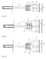
- FIGS. 5 to 8 the use of the efindungsgefflessen console in several steps is described in detail in more detail.
- a building wall 67 which is already provided on the one hand with a first insulation 69.
- a second insulation 71 is applied to the already insulated building wall 67.
- this is shown as the initial state.
- a hole 73 is already drilled for insertion of the rod 17.
- a borehole 75 is provided, the depth of which corresponds at least to the length of the cartridge applied to the front end of the rod 17.
- the console with plugged cartridge 59 is already inserted into the well, the edge 65 of the cartridge 59 limits the depth of immersion.
- a facade element 77 can then be attached to the console 11 ( Fig. 8 ).
- a rail 79 is inserted into the slot 51 and screwed after an adjustment with the screw 53.
- the facade element 77 is then also secured with one or more screws 81 on the rail 79 ( Figure 8 ).
- FIGS. 9 to 14 show the console respectively with different connecting parts 31 and in different facade substructures.
- the latter differ essentially from one another in that the attached to the connecting parts 35 resp. attachable rails 79 are arranged either horizontally or vertically.
- FIGS. 9 to 14 also illustrate how the length of the console can be varied.
- the leg 83 of the rail 79 can be inserted into the slot 51 at different distances during installation on the construction and then be fixed.
- the FIGS. 9 to 14 shows the drawn with a hatched rail 79 an extreme position and drawn with lines rail 79 'the other extreme position of the possible change in length respectively.
- Adjustment. The adjustment described can be used in particular to compensate for inaccuracies of the building wall or differences due to different depths used console bar. In practice, adjustments in the range between approximately 20 and 40 or 50 mm can be made in practice.
- the second adjustment is to attach the connecting part 35 as seen in the longitudinal direction of the rod at different positions on the connecting part 31.
- the elongated connecting part may preferably have a plurality of longitudinally spaced apart holes 47, which can be brought into conformity with the corresponding through holes of the connecting part 31 and in which then screwed to secure the two parts together a screw or a rivet can be used. (see. FIGS. 9 and 10 , resp. 11 and 12 or 13 and 14).
- the distances of the bores 47 from each other are chosen so that with a few basic lengths of the rod 17, the length of the inventive console can be adapted to virtually any thermal insulation thickness. This has the advantage that only a few rod lengths must be kept in stock.
- the length of the console can be changed again by around 20 to 50 mm.
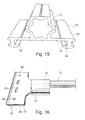
- FIG. 15 shows a further embodiment of a connection part 31, which can be obtained by cutting to length a correspondingly produced aluminum extruded profile.
- the connecting part 31a has a connection plate 85, on which on one side of the receiving channel 37 and arranged on the other side, the guide 42 is formed in the form of a flat guide.
- the guide 42 consists of two opposing Umgriffrucn 84. By the guide 42 of the connecting part 35 projecting connecting portion 48 is guided longitudinally displaceable.
- connection part 31a with a connecting part 35 arranged thereon is shown.
- the connecting part 35 differs from those already described in that it consists of two spaced-apart plates 87, between which the slot 51 is defined. In the plates 87 round holes 89 and slots 91 for the attachment of horizontal rails 79 are provided.
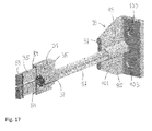
- the rod tip is replaced by a foot part 93.
- the foot part 93 consists of an angle piece 95 and a connection part 97, the latter being attached to the angle piece 95 and fastened by means of a rivet 99. Similar to the connecting part 35 and the connection part 97 is positively encompassed transversely to the longitudinal axis and axially guided.
- a receptacle 101 is arranged for the positive reception of the rod 17, respectively. formed.
- round holes 103 are provided for receiving screws.
- the bracket 11 is provided as follows:
- the rods 17 are provided in 3 to 5, preferably 4 basic lengths starting at about 80 mm and ending at about 250 mm.
- the rods can be produced in the desired basic lengths or cut to length from rods of greater length.
- the rod tip with the undercut is made in a separate operation on a machine tool.
- the longitudinal grooves remain - depending on how much material is turned off - thereby also obtained in the tip of the rod.
- the connector 31 is fixed to the rod 17.
- the appropriate basic length of a semi-finished console is selected and the desired connection part 35 is mounted on the connection part. Only during assembly, the final length of the console is determined.
- a staff should have the following minimum specifications:
Landscapes
- Engineering & Computer Science (AREA)
- General Engineering & Computer Science (AREA)
- Architecture (AREA)
- Mechanical Engineering (AREA)
- Civil Engineering (AREA)
- Structural Engineering (AREA)
- Joining Of Building Structures In Genera (AREA)
- Knitting Of Fabric (AREA)
Abstract
Description
- Die vorliegende Erfindung betrifft eine Konsole gemäss Oberbegriff von Anspruch 1 sowie eine Fassadenunterkonstruktion gemäss Anspruch 14
- Es ist bekannt, eine Ankerstange chemisch in einem Bohrloch in Beton, Mauerwerk oder einem anderen Ankergrund zu befestigen. "Chemische Befestigung oder Verankerung" bedeutet eine Befestigung des Anker Stabs in einem Bohrloch mit einer aushärtenden Masse, die üblicherweise als Mörtel bezeichnet wird. Üblich sind Einoder Mehrkomponentenkunstharze, die auf diesem Anwendungsgebiet oft als Kunstharzmörtel bezeichnet werden, möglich sind auch hydraulisch abbindende Massen, einschliesslich Zementmörtel.
- Die Offenlegungsschrift
DE-OS-100 10 473 A1 - Das kanadische Patent
CA-2 226 584 offenbart ein Verbindungsteil 1,2 mit einem ersten und einem zweiten Kopfstück 1, welche Endstücke mit einem Distanzglied miteinander verbunden sind, das im Wesentlichen den Raum zwischen dem Tragwerk und einer Verkleidung überbrückt. Das Distanzglied ist im Wesentlichen plattenförmig ausgebildet und besteht aus einem Kunststoffbaumaterial. Im Distanzglied und in den Endstücken 1 sind Befestigungsdurchgänge (s.Figur 6 ) vorgesehen, durch welche eine mechanische Befestigung zwischen den Endstücken und dem Distanzglied herstellbar ist. Diese mechanische Befestigung ist durch Befestigungsmittel in den Befestigungsdurchgängen herstellbar. - Das deutsche Gebrauchsmuster
DE-U-20 2007 009 780 - Das Patent
AT-A-511 443 - Das französische Patent mit der Nummer
FR 2 950 637 - Durch die
EP-A-1 203 853 wird eine Befestigungselement zur Abstandsbefestigung von Leisten an einer vertikalen Wand vorgestellt, das eine Schraube umfasst, deren eines Ende zur Befestigung an der Wand ausgestaltet ist und deren anderes Ende ein Gewinde aufweist. Am Gewinde ist mittels eines ein Gegengewinde aufweisenden Bauteils ein Leistenhalter befestigbar, wobei der Leistenhalter gegenüber dem Bauteil frei verdrehbar ist. Die Schraube des Befestigungselements besteht aus einem Bolzen und einer Hülse, die auf den hinteren, aus der Wand herausragenden Abschnitt des Bolzens aufgeschoben ist. Der Bolzen besitzt einen vorderen Bolzenabschnitt, der wie eine Holzschraube ausgebildet ist und ein Gewinde auweist, das in einen Dübel einschraubbar ist. Gemäss derEP-A-1 203 853 wird die thermische Entkopplung allein durch den Dübel, nicht jedoch mit dem Befestigungselement selbst erreicht. - Bei der Sanierung von Altbauten, deren Fassaden bereits eine Dämmschicht aufweisen, muss für das Anbringen der Konsolen zuerst die bestehende Dämmschicht lokal entfernt werden, damit der Fuss der Konsole an der Aussenwand befestigt werden kann. Eine Befestigung der Konsole auf der Dämmschicht ist aus statischen Gründen nicht möglich. Eine solche nachträgliche Aufdämmung ist daher sehr aufwändig und teuer, weil nach dem Anbringen der Konsole die zuvor entfernte Dämmschicht wieder ersetzt werden muss.
- Aufgabe der vorliegenden Erfindung ist es deshalb, eine Konsole und eine Fassadenunterkonstruktion mit der Konsole vorzuschlagen, welche das Problem der Wärmebrücken weitgehend eliminieren. Insbesondere ist ein Ziel, eine Konsole vorzuschlagen, welche sich auch für die nachträgliche Sanierung von bereits gedämmten Fassadenwänden einsetzen lässt. Dabei sollte die Konsole auf unterschiedliche Dämmstärken anpassbar sein, ohne dass sich deren Herstellkosten wesentlich erhöht. Ein weiteres Ziel ist es, eine Fassadenunterkonstruktion vorzuschlagen, die sich mit geringerem Aufwand als herkömmliche Fassadenunterkonstruktionen realisieren lässt.
- Diese und weitere Ziele werden durch den Gegenstand gemäss Anspruch 1 erreicht. Vorteilhafte Ausgestaltungen des erfindungsgemässen Gegenstands sind in den Unteransprüchen definiert.
- Die Erfindung betrifft eine Konsole für die Anbringung von Fassadenelementen an einer Gebäudewand. Diese Konsole, die auch als Fassadenanker bezeichnet werden kann, besitzt einen vorderes Einführende zur Verankerung in einer Gebäudewand und ein hinteres Kopfstück mit einer Befestigungsmöglichkeit für die Befestigung von Fassadenelementen.
- Die erfindungsgemässe Konsole zeichnet sich nun dadurch aus, dass der eingesetzte Stab aus Kunststoff hergestellt ist, in welchem eine Faserverstärkung, vorzugsweise aus Endlosfasern, eingebettet ist. Ausserdem hat das vordere Einführende, das zur Verankerung in einer Wand dient, mindestens einen im Durchmesser verjüngten Zwischenabschnitt. Durch die dadurch bewirkte Hinterschneidung lässt sich der Stab mittels eines Mörtels gut in einem Bohrloch einer Gebäudewand verankern. Die Faserverstärkung kann durch ein bevorzugt mehrheitlich unidirektionales Fasergewebe oder durch im Wesentlichen in Längsrichtung ausgerichtete Rovingstränge resp. Endlosfasern gebildet sein. Diese Konsole hat den Vorteil, dass sie sich auch bei bereits mit einer Dämmung versehenen Wänden einsetzen lässt, da sie sie kein Fussstück aufweist. Der Stab der Konsole kann direkt in einem Bohrloch in der Gehäusewand verankert werden. Weil der Stab eine Faserverstärkung mit mehrheitlich in Längsrichtung ausgerichteten Fasern besitzt, ist die Belastbarkeit der Konsole ausserordentlich hoch. Durch den verjüngten Zwischenabschnitt kann die Auszugskraft so weit erhöht werden, dass die Konsole auch grossen Windlasten widerstehen kann.
- Als Stab soll im Rahmen der vorliegenden Erfindung ein längliches, zylinderförmiges Teil verstanden werden, dessen Länge mindestens 10 mal länger als dessen Dicke und dessen Breite maximal 8 mal grösser als dessen Dicke ist. Im Unterschied dazu ist bei einer Platte die Dicke mindestens eine Grössenordnung kleiner als die anderen zwei Abmessungen, und die Platte ist grundsätzlich eben. Unter einem "Bohrloch" im Sinne der Erfindung ist allgemein ein Loch unabhängig von seiner Herstellung zu verstehen.
- Vorteilhaft ist das vordere Ende des Stabs als Konus- oder Keilspitze ausgebildet und unmittelbar daran anschliessend folgt der verjüngte Zwischenabschnitt. Mittels der Keil- oder Konusspitze lässt sich der Stab gut in ein Bohrloch einführen, auch wenn dieses unter einer Dämmschicht liegt. Auch kann mit der Stabspitze ein vor dem Setzen des Stabs in das Bohrloch eingebrachte Mörtel gut verdrängt werden. Der verdrängte Mörtel kann dann den durch den verjüngten Zwischenabschnitt freigegebene Raum ausfüllen und dann nach der Aushärtung für eine hohe Auszugsfestigkeit des Stabes sorgen.
- Vorteilhaft ist die Faserverstärkung des Stabs aus in Längsrichtung angeordneten Fasern, insbesondere Endlosfasern wie Rovingsträngen oder Filamentfasem, hergestellt. Durch die Verwendung von Endlosfasern, welche mehrheitlich im Wesentlichen die Länge des Stabs aufweisen, sind die Biegefestigkeit und damit die Belastbarkeit der Konsole sehr hoch. Zur Herstellung des Stabs kann die Faserverstärkung beispielsweise als unidirektionales Gelege in eine Spritzgussform eingelegt und dann mit einem geeigneten, die Matrix bildenden Kunststoff umspritzt werden. Die Länge der eingesetzten Endlosfasern entspricht vorzugsweise wenigstens 60%, besonders bevorzugt wenigstens 80% und ganz besonders bevorzugt wenigstens 90% der Länge des Stabs und sind wenigstens 20 mm, vorzugsweise wenigstens 30 mm und besonders bevorzugt wenigstens 50 mm lang. Die Endlosfasern sind im Wesentlichen in Richtung der Zug- und Druckkräfte orientiert, welche bei einer Verbiegung des Stabs auftreten. Die Zugkräfte können folglich von den Fasern optimal aufgenommen werden. Die Kunststoffmatrix kann grundsätzlich auch noch einen Anteil an Kurzschnittfasern aufweisen. Von Bedeutung hingegen ist, dass ein wesentlicher Anteil, insbesondere mehr als 40 Gew.%, vorzugsweise mehr als 60 Gew.% und besonders bevorzugt mehr als 70 Gew.% der Faserarmierung aus in Längsrichtung des Stabes angeordneten Endlosfasern oder Rovingsträngen besteht.
- Bevorzugte Kunststoffe für die Herstellung des Stabs sind Polyamid, Polycarbonat, oder Polystyrol und besonders bevorzugt Polypropylen, da Polypropylen ein niedriges spezifisches Gewicht besitzt und günstig in der Herstellung ist.
- Die hohe Biegesteifigkeit des Stabs wird mit Vorteil dadurch erreicht, dass die Faserverstärkung aus Fasern aus der Gruppe der Glasfasern, Aramidfasern oder Carbonfasern sind. Denkbar sind jedoch auch andere Fasern, wie Natur- oder Kohlestofffasern.
- Der Stab kann im Querschnitt grundsätzlich rund, 3-, 4-, 5-, 6-eckig oder noch mehreckiger (polygon)sein. Vorzugsweise hat der Stab radial abstehende, axial verlaufende Rippen. Durch die Rippen kann die Steifigkeit des Stabs weiter verbessert werden. Andererseits kann durch eine Rippenkonstruktion auch Material eingespart werden, sodass das Produkt trotz hoher Belastbarkeit ein geringes Gewicht aufweisen kann. Vorzugsweise beträgt die Rippenhöhe das 0.05 bis 0.5-fache des Stabradius, vorzugsweise das 0.1 bis 0.4-fache des Stabradius, und besonders bevorzugt das 0.2 bis 0.3-fache des Stabradius. Die Rippen können einen unterschiedlichen Querschnitt haben. Bevorzugt ist der Querschnitt der Rippen trapez- oder dreieckförmig. Durch die Rippen auch im Bereich angrenzend an das vordere Einführende wird die Oberfläche vergrössert, sodass nach dem Verkleben des Einführendes in einem Bohrloch sich auch die Auszugskraft vergrössert.
- Eine vorteilhafte Ausführungsform sieht vor, dass der Stab im Querschnitt eine Sternform hat, d.h. insgesamt 4,5, 6 oder mehr Rippen am Umfang ausgeformt sind. Eine solche Konstruktion hat sich in der Praxis auch aus Symmetriegründen bewährt.
- Dadurch, dass das vordere Ende als Keil- oder Konusspitze ausgebildet ist, kann der Stab der Konsole gut in ein Bohrloch eingeführt werden. Durch die Längsrippen, die auch im Bereich der Spitze teilweise vorhanden sind, kann der Mörtel im Bohrloch gut verdrängt werden, sodass sich der Stab leicht einführen lässt. Vorteilhaft ist der grösste Durchmesser des Einführendes um 0.5 bis 4, vorzugsweise 1 bis 3 mm kleiner als der grösste Durchmesser des Stabes. Dies hat den Vorteil, dass eine Klebemittelpatrone auf das vordere Ende aufgesetzt werden kann, ohne dass der Durchmesser des aus der Gebäudewand kragenden Stabs dadurch überschritten würde.
- Zweckmässigerweise ist das Kopfstück mit der Befestigungsmöglichkeit am Stab befestigt und vorzugsweise auf diesen aufgesetzt. Dies hat den Vorteil, dass unterschiedliche Befestigungseinrichtungen oder Tragteile am Stab befestigt werden können.
- Vorteilhaft ist das Kopfstück mit der Befestigungsmöglichkeit zweiteilig ausgeführt und weist ein Anschlussteil und ein Verbindungsteil auf. Dabei ist das als Aufsteckteil ausgeführte Anschlussteil am Stabende befestigt, und das Verbindungsteil ist am Anschlussteil befestigt resp. befestigbar.
- Gemäss einer bevorzugten Ausführungsform sind am Anschlussteil und dem Verbindungsteil in Längsrichtung mehrere voneinander beabstandete Verbindungspositionen definiert. Dies hat den grossen Vorteil, dass die effektive Länge der ganzen Konsole bei gegebener Länge des Verbund-Kunststoffstabs in einem bestimmten Bereich variierbar ist. Dies ermöglicht es, mit 3 oder 4 verschiedenen Grundlängen des Verbund-Kunststoffstabs alle beim heutigen Hausbau anzutreffenden Dämmstoffstärken abzudecken. Das Anschlussteil und gegebenenfalls auch das Verbindungsteil können beispielsweise als stranggepresstes Profil aus Aluminium kostengünstig hergestellt werden.
- Vorzugsweise ist zwischen dem Anschlussteil und dem Verbindungsteil eine Längsführung ausgebildet. Dies hat den Vorteil, dass Anschlussteil und Verbindungsteil quer zur Längsachse des Stabs formschlüssig umfasst sind, und eine hohe Stabilität der Konsole gewährleistet ist.
- Das Verbindungsteil hat einen Verbindungsabschnitt, der zur Verbindung mit dem Anschlussteil dient, und einen Befestigungsabschnitt, an dem eine Profilschiene befestigbar ist. Der Verbindungsabschnitt hat in Richtung der Längsachse eine grössere Ausdehnung als das Anschlussteil. Dies ermöglicht, die effektive Länge der Konsole In einem bestimmten Bereich anzupassen, indem der Verbindungsabschnitt näher oder weiter entfernt zum vorderen Ende des Stabes am Anschlussteil befestigt wird. Diese Anpassung kann ohne Probleme auch auf der Baustelle vorgenommen werden. Im Befestigungsabschnitt des Verbindungsteils ist ein Schlitz vorgesehen, in dem eine Profilschiene aufnehm- und befestigbar ist. Das Vorsehen eines Schlitzes hat den Vorteil, dass eine Justierung in einem bestimmten Längenbereich möglich ist, indem die Schiene unterschiedlich weit in den Einführschlitz eingeschoben wird. Mit der beschriebenen Justiermöglichkeit lassen sich Unebenheiten einer Gebäudewand ausgleichen.
- Zweckmässigerweise weist das Verbindungsteil einen als Kragarm dienenden Befestigungsabschnitt mit wenigstens einem Befestigungsdurchgang auf. Als Befestigungsdurchgang kann ein geschlossener oder halboffener Kanal dienen, in welchen eine Schraube eindrehbar ist.
- Gemäss einer bevorzugten Ausführungsform ist auf das vordere Ende des Stabs eine einen Mörtel enthaltende Patrone aufgebracht. Als Mörtel soll im Rahmen der vorliegenden Erfindung jede aushärtende Masse, sei sie aus einer, zwei oder noch mehr Komponenten zusammengesetzt, verstanden werden.
- Die Patrone ist üblicherweise als Hohlzylinder ausgebildet, dessen vorderes Ende durch einen Boden verschlossen ist und dessen hinteres Ende eine Öffnung aufweist. Durch die Öffnung kann ein Behälter mit einer Mörtelmasse in die Patrone eingefüllt sein. Denkbar ist, dass die Mörtelmasse mittels lediglich einer Trennwand von der Umgebung abgetrennt ist. Je nach Einsatzgebiet kann auch ein 2-Komponentenharz eingesetzt werden. In diesem Fall sind zwei voneinander getrennte Behälter nötig. Diese können ineinander verschachtelt oder als doppelwandiger Behälter ausgeführt sein. Die Patrone kann also einen äusseren Behälter und einen inneren Behälter aufweisen, wobei im Zwischenraum zwischen dem äusseren und dem inneren Behälter die eine Harzkomponente und im inneren Behälter die zweite Harzkomponente aufgenommen ist. Denkbar ist auch, dass die Mörtelpatrone losgelöst von der Konsole zuerst in das Bohrloch eingeführt wird.
- Durch das Vorsehen eines radial nach aussen abstehenden Rand am hinteren Ende der Patrone kann sichergestellt werden, dass die Patrone nicht zu weit in ein zu tief gebohrtes Loch eintauchen kann. Auch wird damit gleichzeitig eine Grobjustierung erreicht.
- Gegenstand der vorliegenden Erfindung ist auch ein Konsolensystem umfassend eine erfindungsgemässe Konsole und eine Mörtelpatrone. Dabei können Konsole und Mörtelpatrone als separate Einheiten eingesetzt werden, d.h. bei dem Konsolensystem kann die Mörtelpatrone zuerst in das Bohrloch eingesetzt und anschliessend der Stab der Konsole in die Patrone eingesteckt werden.
- Ein weiterer Gegenstand der vorliegenden Erfindung ist eine Fassadenunterkonstruktion umfassend
- eine Tragkonstruktion,
- eine Mehrzahl von erfindungsgemässen Konsolen, deren vordere Enden in oder an der Tragkonstruktion befestigt sind und an deren hinteren Enden eine Verkleidung angeordnet ist.
- Vorteilhaft ist das vordere Stabende mittels eines Klebers oder Mörtels stoffschlüssig mit der Tragkonstruktion verbunden. Der Stab kann mit Hülse und Klebemörtel gesetzt werden oder in Beton, Mauerwerk oder einem anderen festen Untergrund direkt mit Mörtel montiert werden.
- Ein weiterer, unabhängiger Gegenstand der Erfindung ist eine Konsole für die Anbringung von Fassadenelementen an einer Gebäudewand mit
- einem als Distanzteil dienenden Stab, an dessen einem Ende ein Fussteil zur Befestigung der Konsole an einer Gebäudewand,
- einem Kopfstück, das dem Fussteil gegenüberliegend am Stab angeordnet ist und eine Befestigungsmöglichkeit für die Anbringung von Fassadenelementen besitzt. Die erfindungsgemässe Konsole ist dadurch gekennzeichnet, dass das Kopfstück mit der Befestigungsmöglichkeit aus zwei Teilen hergestellt ist und ein Anschlussteil und ein Verbindungsteil aufweist. Diese Art der Verstellbarkeit kann auch bei Konsolen mit einem separaten Fussteil, das mit Hilfe von Schrauben an oder auf die Gebäudewand montiert wird, vorteilhaft eingesetzt werden. Die Herstellung aus zwei Teilen hat den Vorteil, dass die Länge der Konsole in einem bestimmten Längenbereich anpassbar ist.
- Vorteilhaft ist zwischen dem Anschlussteil und dem Verbindungsteil eine Längsführung vorgesehen ist. Die Längsführung sorgt für eine grosse Stabilität quer zur Längsachse des Stabes, auch wenn das Kopfstück aus zwei Teilen hergestellt ist. Ausserdem können Anschlussteil und Verbindungsteil relativ zueinander verschoben werden. Die relative Längsverschiebbarkeit der Teile kann vergrössert werden, indem der Verbindungsabschnitt des Verbindungsteils in Achsrichtung gesehen länger als das Anschlussteil ist.
- Ausführungsbeispiele der Erfindung werden nun unter Bezugnahme auf die Zeichnungen beschrieben. Es zeigt:
- Figur 1:
- Eine erfindungsgemässe Konsole mit separater Patrone mit Mörtel;
- Figur 2:
- Die Konsole von
Fig. 1 mit aufgesetzter Patrone; - Figuren 3 und 4:
- Die beiden Teile eines Kopfstücks für die Befestigung von Fassadenteilen bestehend aus einem Anschlussteil (
Fig. 3 ) dargestellt in der Perspektive, Front- und Seitenansicht, und einem Verbindungsteil dargestellt in der Perspektive, Seitenansicht und Draufsicht; - Figur 5:
- Eine mit einer Dämmung versehene Gebäudewand mit einem Bohrloch zur Aufnahme des Konsolenstabs;
- Figur 6:
- Die Gebäudewand von
Fig. 5 mit ins Bohrloch eingeführtem Stab; - Figur 7:
- Der im Bohrloch fest verklebte Stab;
- Figur 8:
- Eine Fassadenunterkonstruktion mit der erfindungsgemässen Konsole;
- Figuren 9:
- eine in einer Gebäudewand versetzte Konsole mit einem daran montierten Verbindungsteil einer ersten Art und einer horizontalen Profilschiene in zwei unterschiedlichen Positionen;
- Figur 10:
- wie
Figur 9 , jedoch mit nach aussen versetzt angeordnetem Verbindungsteil; - Figuren 11:
- eine in einer Gebäudewand versetzte erfindungsgemässe Konsole mit einem daran montierten Verbindungsteil einer zweiten Art und einer vertikalen Profilschiene in zwei unterschiedlichen Positionen;
- Figur 12:
- wie
Figur 11 , jedoch mit nach aussen versetzt angeordnetem Verbindungsteil; - Figur 13:
- eine in einer Gebäudewand versetzte erfindungsgemässe Konsole mit einem daran montierten Verbindungsteil einer dritten Art und einer vertikalen Profilschiene in zwei unterschiedlichen Positionen;
- Figur 14:
- wie
Figur 13 , jedoch mit nach aussen versetzt angeordnetem Verbindungsteil; - Figur 15:
- eine perspektivische Ansicht einer weiteren Ausführungsform eines Anschlussteils mit Stab;
- Figur 16:
- das Anschlussteil gemäss
Fig. 15 mit einem Verbindungsteil der dritten Art. und - Figur 17:
- eine Konsole mit einem Fuss und einem Kopfstück in perspektivischer Ansicht.
- Die
Figuren 1 und 2 zeigen eine erfindungsgemässe Konsole 11 mit einem Stab 17 mit einem vorderen Einführende 13, das für die Aufnahme in einem Bohrloch in einer Gebäudewand gedacht ist und einem am gegenüberliegenden Ende des Stabs angeordneten Kopfstück 15 zur Befestigung von Profilschienen, an denen die Fassadenelemente angeordnet werden können. Denkbar ist jedoch auch, dass die Fassadenelemente auch direkt am Kopfstück 15 befestigt werden. Das Einführende 13 ist mittels eines verjüngten Abschnitts 19, der einen kleineren Durchmesser hat als der übrige Stab 17 und die dickste Stelle 21 des vorderen Endabschnitts 13, vom Schaft 17 abgesetzt. Den Übergang zwischen dem verjüngten Abschnitt 19 und dem Schaft 17 bildet ein Ringabsatz 25. Vom Ringabsatz 25 in Richtung Spitze 27 nimmt der Durchmesser des Stabes kontinuierlich zu, bis er am Punkt 21 den grössten Durchmesser erreicht. Nach dem Punkt 21 nimmt der Durchmesser bis zur Spitze 27 kontinuierlich ab und definiert dabei eine Keil- oder eine Konusspitze 23. Unter kontinuierlicher Zu- resp. Abnahme soll dabei eine gleichmässige oder ungleichmässige Zu- resp. Abnahme verstanden werden, sodass die entsprechenden Konturen im Längsschnitt linien- oder bogenförmig sind. - Der Stab 17 ist aus einem Faserverbundwerkstoff hergestellt. Der Faserverbundwerkstoff besteht aus einer Matrix und eine darin angeordnete Faserverstärkung aus in Längsrichtung angeordneten (Endlos-)Fasern, insbesondere Rovingsträngen oder Filamentfasern. Aber auch Langfasern oder unidirektionale Gelege in Längsrichtung des Stabes angeordnet sind als Fasern einsetzbar. Die Matrix des Verbundwerkstoffs ist aus einem geeigneten Kunststoff gebildet. Durch die Verwendung eines Verbundwerkstoffes ist ein Stab 17 realisiert, der den Belastungen von zu tragenden Fassadenelementen 77 gewachsen ist und die Bildung von praktisch vollständig Wärmebrücken unterbindet.
- Zu beachten ist, dass der Durchmesser am Punkt 21 etwas kleiner sein kann als der rückwärtige Schaftdurchmesser, damit - wie weiter unten noch erklärt wird - eine Mörtelpatrone auf das Einführende 13 aufgesteckt werden kann.
- Der Stab 17 hat am Umfang in Achsrichtung 28 (
Fig. 1 ) verlaufende Längsrippen 29 ausgebildet mit einem im Wesentlichen dreieckförmigen Querschnitt. Dies verleiht dem Stab im Querschnitt eine Sternform. Durch die Längsrippen 29 ergibt sich eine Vergrösserung der Mantelfläche, sodass bei einer Verklebung des vorderen Endabschnittes in einem Bohrloch eine höhere Auszugskraft resultiert. - Am hinteren Ende 15 des Stabs 17 ist ein Anschlussteil 31 angeordnet, welches in der
Figur 3 näher im Detail gezeigt ist. Das Anschlussteil 31 kann mittels geeigneter Befestigungsmittel, wie z.B. Schrauben oder Nieten, am Schaft des Stabes 17 befestigt sein. Denkbar ist jedoch auch, dass das Anschlussteil mit dem Stab stoffschlüssig mittels eines Klebers verbunden ist. Zur Erhöhung der Stabilität der Verbindung zwischen Stab 17 und Anschlussteil 31 besitzt letzteres gemässFigur 3 eine hohlzylindrische Aufnahme 37, in die das hintere Ende des Schaftes formschlüssig eingesetzt und in dieser Lage befestigt oder befestigbar ist. Das Anschlussteil 31 ist gemäss dem dargestellten Ausführungsbeispiel ein quaderförmiger Metallblock 33, vorzugsweise aus Aluminium, in welchem eine dem Aussenprofil des Schaftes entsprechende Aufnahme 37 in Gestalt eines Kanals ausgebildet ist. Eine im Anschlussteil 31 vorgesehene Durchgangsöffnung 41 dient der Aufnahme einer Schraube oder Niete 38 zur Befestigung desselben am Schaft 17 (s.Figuren 5 und 6 ). - Das Anschlussteil 31 dient der Befestigung eines Verbindungsteils 35, das am Anschlussteil 31 längsverschieblich geführt und in unterschiedlichen Positionen befestigbar ist. Dies hat den grossen Vorteil, dass die Gesamtlänge der Konsole bei der Produktion in einem bestimmten Bereich variierbar ist. Zu diesem Zweck ist zwischen dem Anschlussteil 31 und dem Verbindungsteil 35 eine parallel zur Stabachse 28 verlaufende Längsführung vorgesehen. Diese Längsführung ist im gezeigten Ausführungsbeispiel durch zwei seitliche Leisten 39 realisiert, die an zwei einander gegenüberliegenden Flachseiten des Anschlussteils 31 ausgebildet sind und in die ein U-förmiges Kopfstück 43 des Verbindungsteils 35 eingreifen kann.
- Das U-förmige Kopfstück 43 besitzt zwei Schenkel 45a,45b, welche zwischen den Leisten 39 des Anschlussteils 31 Platz finden. In den Schenkeln 45a,45b sind in Übereinstimmung mit der Durchgangsöffnung 41 des Anschlussteils 31 jeweils ein oder mehrere Löcher 47a,47b vorgesehen, die zur Verbindung mit dem Anschlussteil 31 mit der Durchgangsöffnung 41 in Übereinstimmung gebracht werden können. Wenn in Längsrichtung des Verbindungsteils 35 mehrere Löcher 47a,47b vorgesehen sind, kann die Länge der Konsole noch bei der Produktion angepasst werden.
- Das Verbindungsteil 35 besitzt einen Verbindungsabschnitt 48 zur Verbindung mit dem Anschlussteil 31 und einen Befestigungsabschnitt 49 zur Befestigung einer Profilschiene oder eines Fassadenelements. Der Befestigungsabschnitt 49 besitzt einen Schlitz 51, der der Aufnahme eines flachen Befestigungselements, z.B. des Schenkels einer T-Profilschiene, dient. Fixiert wird das eingeschobene Befestigungselement mittels einer Schraube 53, welche in einen Kanal 55, der sich rechtwinklig zur Längsachse des Stabs erstreckt, einschraubbar ist.
- Zur Verankerung des vorderen Einführendes 13 in einem Bohrloch ist eine mit einem Mörtel 57 teilgefülfte Patrone 59 vorgesehen, welche auf das Einführende 13 aufsteckbar ist (
Figuren 1 und 2 ). Der Mörtel kann schon ab Werk in die Patrone 59 eingefüllt sein und die Patrone ist dann an ihrer Öffnung 63 mit einem Deckel verschlossen, damit der Mörtel nicht eintrocknet. Der Deckel wird entweder vor der Montage entfernt oder beim Setzen des Stabs 17 von der Stabspitze 27 durchstossen. Denkbar ist es auch, dass der Mörtel erst kurz vor der Montage der Konsole 11 in die Patrone 59 gefüllt wird. Die Patrone 59 ist vorzugsweise als Hohlzylinder ausgebildet, dessen vorderes Ende durch einen Boden 61 verschlossen ist und dessen hinteres Ende die Öffnung 63 aufweist. Am hinteren Ende der Patrone ist ein radial nach aussen abstehender Rand 65 vorgesehen. Dieser hat den Zweck, die Patrone am Rand des Bohrlochs zurückzuhalten. - In den
Figuren 5 bis 8 ist die Verwendung der efindungsgemässen Konsole in mehreren Verfahrensschritten näher im Detail beschrieben. Gezeigt ist eine Gebäudewand 67, welche auf der einen Seite bereits mit einer ersten Dämmung 69 versehen ist. Zwecks Sanierung ist auf die bereits gedämmte Gebäudewand 67 eine zweite Dämmung 71 aufgebracht. InFigur 5 ist dies als Ausgangszustand dargestellt. Durch die Dämmungen 69,71 ist schon ein Loch 73 zum Einführen des Stabs 17 gebohrt. In der Gebäudewand 67 selbst ist ein Bohrloch 75 vorgesehen, dessen Tiefe mindestens der Länge der Patrone, die auf das vordere Ende des Stabs 17 aufgebracht ist, entspricht. InFigur 6 ist die Konsole mit aufgesteckter Patrone 59 bereits ins Bohrloch eingesteckt, wobei der Rand 65 der Patrone 59 die Eintauchtiefe begrenzt. Wird nun der Stab weiter in das Bohrloch gedrückt, wird der Behälter mit dem Mörtel 57 zerstört und der Mörtel durch nicht näher gezeigte Durchtrittsöffnungen im Patronenmantel ins Bohrloch gedrückt (Fig. 7 ). Idealerweise füllt der Mörtel dann die Freiräume zwischen der Bohrlochwandung und dem Einführende vollständig aus. Nach dem Aushärten der Mörtelmasse kann dann an der Konsole 11 ein Fassadenelement 77 befestigt werden (Fig. 8 ). Dazu wird eine Profilschiene 79 in den Schlitz 51 eingeführt und nach einer Justierung mit der Schraube 53 festgeschraubt. Das Fassadenelement 77 wird sodann ebenfalls mit einer oder mehreren Schrauben 81 an der Profilschiene 79 befestigt (Fig.8 ). - Die
Figuren 9 bis 14 zeigen die Konsole jeweils mit unterschiedlichen Verbindungsteilen 31 und in unterschiedlichen Fassadenunterkonstruktionen. Letztere unterscheiden sich im Wesentlichen dadurch voneinander, dass die an den Verbindungsteilen 35 befestigten resp. befestigbaren Profilschienen 79 entweder horizontal oder vertikal angeordnet sind. - Die
Figuren 9 bis 14 veranschaulichen auch, wie die Länge der Konsole variiert werden kann. Gemäss einer ersten Verstellmöglichkeit kann der Schenkel 83 der Schiene 79 bei der Montage auf dem Bau unterschiedlich weit in den Schlitz 51 eingeschoben und dann fixiert werden. In denFiguren 9 bis 14 zeigt die mit einer Schraffur eingezeichnete Profilschiene 79 die eine Extremposition und die mit Linien gezeichnete Profilschiene 79' die andere Extremposition der möglichen Längenveränderung resp. Justierung. Die beschriebene Verstellmöglichkeit kann insbesondere dazu benützt werden, um Ungenauigkeiten der Gebäudewand oder Differenzen wegen unterschiedlich tief eingesetztem Konsolenstab auszugleichen. In der Praxis können so Justierungen im Bereich zwischen ungefähr 20 und 40 oder 50 mm vorgenommen werden. - Die zweite Verstellmöglichkeit besteht darin, das Verbindungsteil 35 in Längsrichtung des Stabs gesehen an unterschiedlichen Positionen am Anschlussteil 31 zu befestigen. Von dieser Möglichkeit kann bereits bei der Produktion oder erst auf der Baustelle Gebrauch gemacht werden. Zu diesem Zweck kann das längliche Verbindungsteil vorzugsweise mehrere in Längsrichtung voneinander beabstandete Bohrungen 47 aufweisen, die mit den entsprechenden Durchgangsöffnungen des Anschlussteils 31 in Übereinstimmung gebracht werden können und in die dann zur Befestigung der beiden Teile miteinander eine Schraube eingeschraubt oder eine Niete eingesetzt werden kann. (vgl.
Figuren 9 und 10 , resp. 11 und 12 oder 13 und 14). Die Abstände der Bohrungen 47 voneinander sind so gewählt, dass mit wenigen Grundlängen des Stabs 17 sich die Länge der erfindungsgemässen Konsole an praktisch jede Wärmedämmstärke anpassen lässt. Dies hat den Vorteil, dass nur wenige Stablängen vorrätig gehalten werden müssen. Mit der zweiten Verstellmöglichkeit kann die Länge der Konsole noch einmal um rund zwischen 20 und 50 mm verändert werden. - Beide erwähnten Verstellmöglichkeiten zusammen erlauben somit, die effektive Länge der Konsole zwischen ungefähr 20 mm und 90 mm zu verändern.
-
Figur 15 zeigt eine weitere Ausführungsform eines Anschlussteils 31, das durch Ablängen eines entsprechend hergestellten Aluminium-Strangpressprofils erhalten werden kann. Das Anschlussteil 31a besitzt eine Anschlussplatte 85, an welcher auf der einen Seite der Aufnahmekanal 37 angeordnet und auf der anderen Seite die Führung 42 in Gestalt einer Flachführung ausgebildet ist. Die Führung 42 besteht aus zwei einander gegenüberliegenden Umgriffleisten 84. Durch die Führung 42 ist der vom Verbindungsteil 35 abragende Verbindungsabschnitt 48 längsverschieblich geführt. - In der
Figur 16 ist das Anschlussteil 31a mit einem daran angeordnet Verbindungsteil 35 gezeigt. Das Verbindungsteil 35 unterscheidet sich von den bereits beschriebenen dadurch, dass dieses aus zwei voneinander beabstandeten Platten 87 besteht, zwischen denen der Schlitz 51 definiert ist. In den Platten 87 sind Rundlöcher 89 und Langlöcher 91 für die Befestigung von horizontalen Profilschienen 79 vorgesehen. - In
Figur 17 ist die Stabspitze durch ein Fussteil 93 ersetzt. Das Fussteil 93 besteht aus einem Winkelstück 95 und einem Anschlussteil 97, wobei letzteres auf das Winkelstück 95 aufgesteckt und mittels einer Niete 99 befestigt ist. Ähnlich dem Verbindungsteil 35 ist auch das Anschlussteil 97 quer zur Längsachse formschlüssig umfasst und axial geführt. Am Anschlussteil ist eine Aufnahme 101 für die formschlüssige Aufnahme des Stabs 17 angeordnet resp. angeformt. Im Winkelstück 95 sind Rundlöcher 103 für die Aufnahme von Schrauben vorgesehen. - Die Konsole 11 wird wie folgt bereitgestellt: Die Stäbe 17 werden in 3 bis 5, vorzugsweise 4 Grundlängen beginnend bei ca. 80 mm und endend bei ca. 250 mm bereitgestellt. Die Stäbe können dabei in den gewünschten Grundlängen produziert oder von Stäben einer grösseren Länge abgelängt werden. Die Stabspitze mit der Hinterschneidung wird in einem separaten Arbeitsgang auf einer Werkzeugmaschine hergestellt. Die Längsrillen bleiben - je nachdem wie viel Material abgedreht wird - dabei auch in der Stabspitze erhalten. Danach wird das Anschlussteil 31 am Stab 17 befestigt. Entsprechend den Erfordernissen eines Arbeitsauftrags wird die passende Grundlänge einer halbfertigen Konsole ausgewählt und das gewünschte Verbindungsteil 35 am Anschlussteil montiert. Erst bei der Montage wird dabei die definitive Länge der Konsole festgelegt.
- Ein Stab soll folgende Mindestspezifikationen aufweisen:
-
- 11
- Konsole
- 13
- vorderes Einführende
- 15
- Hinteres Kopfstück
- 17
- Stab
- 19
- verjüngter Abschnitt des vorderen Einführendes
- 21
- dickste Stelle der Einführspitze
- 23
- Keilsspitze des Stabs
- 25
- Ringabsatz
- 27
- Spitze
- 29
- Längsrippen
- 31
- Anschlussteil
- 33
- Metallblock
- 35
- Verbindungsteil
- 37
- Kanal
- 38
- Schraube oder Niete zur Befestigung des Anschlussteils am Schaft 17
- 39
- Seitliche Leisten zur Längsführung
- 41
- Durchgangsöffnung
- 42
- Führung
- 43
- U-förmiges Kopfstück
- 45a,45b
- Schenkel des Verbindungsteils 35
- 47a,47b
- Löcher in den Schenkeln
- 48
- Verbindungsabschnitt
- 49
- Befestigungsabschnitt (Kragarm)
- 51
- Schlitz
- 53
- Schraube
- 55
- Kanal
- 57
- Mörtel
- 59
- Patrone
- 61
- Boden
- 63
- Öffnung der Patrone
- 65
- Rand
- 67
- Gebäudewand
- 69
- erste Dämmung
- 71
- zweite Dämmung
- 73
- Loch durch die Dämmungen
- 75
- Bohrloch in der Gebäudewand
- 77
- Fassadenelement
- 79
- Profilschiene (Winkelprofil)
- 81
- Schrauben
- 83
- Schenkel der Profilschiene
- 85
- Anschlussplatte
- 87
- beabstandete Platten eines Verbindungsteils
- 89
- Rundlöcher
- 91
- Langlöcher
- 93
- Fussteil
- 95
- Winkelstück
- 97
- Anschlussteil
- 99
- Niete
- 101
- Aufnahme
- 103
- Rundlöcher im Winkelstück
Claims (15)
- Konsole (11) für die Anbringung von Fassadenelementen an einer Gebäudewand mit- einem Stab, der ein vorderes Einführende (13) aufweist zur Verankerung in einer Gebäudewand (67),- einem hinteren Kopfstück (15), das am hinteren Ende des Stabs angeordnet ist und eine Befestigungsmöglichkeit (33,35) für die Anbringung von Fassadenelementen besitzt,
dadurch gekennzeichnet,
dass der Stab aus Kunststoff hergestellt ist und eine in der Kunststoffmatrix integrierte Faserverstärkung besitzt, und
das vordere, zur Verankerung in einer Gebäudewand vorgesehene Einführende (13) mindestens einen im Durchmesser verjüngten Zwischenabschnitt (19) aufweist. - Konsole nach Anspruch 1, dadurch gekennzeichnet, dass das vordere Ende (13) des Stabs als Konus- oder Keilspitze (23) ausgebildet ist und daran anschliessend der verjüngte Zwischenabschnitt folgt.
- Konsole nach Anspruch 1 oder 2, dadurch gekennzeichnet, dass die Faserverstärkung des Stabs aus in Längsrichtung angeordneten Fasern, insbesondere Rovingsträngen oder Filamentfasern, hergestellt ist.
- Konsole nach einem der Ansprüche 1 bis 3, dadurch gekennzeichnet, dass der Schaft (17) des Stabs radial abstehende, axial verlaufende Rippen (29) aufweist.
- Konsole nach Anspruch 4, dadurch gekennzeichnet, dass die Rippenhöhe das 0.05 bis 0.5-fache des Stabradius, vorzugsweise das 0.1 bis 0.4-fache des Stabradius, und besonders bevorzugt das 0.2 bis 0.3-fache des Stabradius beträgt.
- Konsole nach einem der Ansprüche 1 bis 5, dadurch gekennzeichnet, dass der grösste Durchmesser des Einführendes (13) um 0.5 bis 4, vorzugsweise 1 bis 3 mm kleiner ist als der grösste Durchmesser des Stabes (17).
- Konsole nach einem der Ansprüche 1 bis 6, dadurch gekennzeichnet, dass das Kopfstück (15) mit der Befestigungsmöglichkeit (15) zweiteilig ausgeführt ist und ein Anschlussteil (31) und ein Verbindungsteil (35) aufweist.
- Konsole nach einem der Ansprüche 1 bis 7, dadurch gekennzeichnet, dass am Anschlussteil (31) und dem Verbindungsteil (35) in Längsrichtung mehrere voneinander beabstandete Verbindungspositionen definiert sind.
- Konsole nach einem der Ansprüche 1 bis 8, dadurch gekennzeichnet, dass zwischen dem Anschlussteil (31) und dem Verbindungsteil (35) eine Längsführung vorgesehen ist.
- Konsole nach einem der Ansprüche 1 bis 9, dadurch gekennzeichnet, dass im Verbindungsteil (35) ein in Längsrichtung des Stabs sich erstreckender Schlitz (51) vorgesehen ist, in welchem eine Profilschiene (79) befestigbar ist.
- Konsole nach einem der Ansprüche 1 bis 10, dadurch gekennzeichnet, dass auf das vordere Einführende eine einen Mörtel (57) enthaltende Patrone (59) aufgesetzt ist.
- Konsole für die Anbringung von Fassadenelementen an einer Gebäudewand mit- einem Stab (17) mit einem Fussteil zur Befestigung der Konsole an einer Gebäudewand,- einem Kopfstück (15), das dem Fussteil gegenüberliegend am anderen Ende des Stab angeordnet ist und eine Befestigungsmöglichkeit für die Anbringung von Fassadenelementen besitzt.
dadurch gekennzeichnet,
dass das Kopfstück (15) mit der Befestigungsmöglichkeit aus zwei Teilen hergestellt ist und ein Anschlussteil (15) und ein Verbindungsteil (35) aufweist. - Konsole nach Anspruch 12, dadurch gekennzeichnet, dass zwischen dem Anschlussteil und dem Verbindungsteil eine Längsführung vorgesehen ist..
- Fassadenunterkonstruktion umfassend- eine Tragkonstruktion- eine Mehrzahl von Konsolen gemäss einem der Ansprüche 1 bis 13, deren vordere Enden in der Tragkonstruktion verankerbar und an deren hinteren Enden eine Verkleidung anbringbar ist; und- eine Verkleidung, die an den hinteren Enden der Tragelemente befestigbar ist
- Fassadenunterkonstruktion nach Anspruch 14, dadurch gekennzeichnet, dass das vordere Ende des Stabs mittels eines Klebers oder Mörtels stoffschlüssig mit der Tragkonstruktion verbunden ist.
Applications Claiming Priority (1)
| Application Number | Priority Date | Filing Date | Title |
|---|---|---|---|
| CH01297/13A CH708361A1 (de) | 2013-07-22 | 2013-07-22 | Fassadenanker. |
Publications (3)
| Publication Number | Publication Date |
|---|---|
| EP2853654A2 true EP2853654A2 (de) | 2015-04-01 |
| EP2853654A3 EP2853654A3 (de) | 2015-10-14 |
| EP2853654B1 EP2853654B1 (de) | 2022-09-07 |
Family
ID=50023350
Family Applications (1)
| Application Number | Title | Priority Date | Filing Date |
|---|---|---|---|
| EP14178089.0A Active EP2853654B1 (de) | 2013-07-22 | 2014-07-22 | Konsole und fassadenunterkonstruktion mit der konsole |
Country Status (3)
| Country | Link |
|---|---|
| EP (1) | EP2853654B1 (de) |
| CH (1) | CH708361A1 (de) |
| DK (1) | DK2853654T3 (de) |
Cited By (5)
| Publication number | Priority date | Publication date | Assignee | Title |
|---|---|---|---|---|
| WO2017153049A1 (de) | 2016-03-10 | 2017-09-14 | Giller, Jutta | Abstandshalter und befestiger für durch eine fassade hindurch am gebäude zu befestigenden teile |
| DE102018001932A1 (de) | 2017-09-01 | 2019-03-07 | Jutta Giller | Abstandshalter und Befestiger für durch eine Fassade hindurch an Gebäuden zu befestigende Teile |
| DE102018008598A1 (de) | 2018-10-31 | 2020-04-30 | Jutta Giller | Abstandshalter und Befestiger für durch eine Fassade hindurch am Gebäude zu befestigenden Teile |
| EP3862580A1 (de) | 2020-02-07 | 2021-08-11 | Adolf Würth GmbH & Co. KG | Befestigungsvorrichtung mit schraube und daran drehbar und verschiebegesichert angebrachtem thermischen isolationskörper |
| DE102022105264A1 (de) | 2022-03-07 | 2023-09-07 | Ulrich Wagner | Ankerstangen-Befestigungsbaugruppe für eine vorgehängte hinterlüftete Fassade, Fassadenbefestigungssystem und vorgehängte hinterlüftete Fassade |
Citations (6)
| Publication number | Priority date | Publication date | Assignee | Title |
|---|---|---|---|---|
| CA2226584A1 (en) | 1998-03-13 | 1999-09-13 | Jan Vrana | Composite structural member with sheet metal flanges |
| DE10010473A1 (de) | 2000-03-03 | 2001-09-20 | Tox Duebel Werk | Verfahren und Verbundanker zur stoffschlüssigen Halterung eines Befestigungselementes, insbesondere für poröses Mauerwerk |
| EP1203853A2 (de) | 2000-11-02 | 2002-05-08 | Werner Müller | Befestigungselement und Verfahren zu dessen Montage |
| DE202007009780U1 (de) | 2007-07-11 | 2007-10-18 | Schröter, Bernd | Befestigungskonsole für Fassadenelemente an Gebäudewänden |
| FR2950637A1 (fr) | 2009-09-30 | 2011-04-01 | Jean Christophe Valdebouze | Paroi isolee a elements de maconnerie pre-perces |
| AT511443A4 (de) | 2011-11-07 | 2012-12-15 | Galehr Kornelia | Einrichtung zur befestigung einer last |
Family Cites Families (11)
| Publication number | Priority date | Publication date | Assignee | Title |
|---|---|---|---|---|
| US2021610A (en) * | 1934-06-14 | 1935-11-19 | Quint George | Refractory anchor |
| US3909907A (en) * | 1974-04-01 | 1975-10-07 | Carborundum Co | Method for installing furnace linings |
| CH598438A5 (en) * | 1976-12-23 | 1978-04-28 | Braendli August | Clamp for facing and internal lining panels for wall or ceiling |
| US4584814A (en) * | 1984-02-21 | 1986-04-29 | Manville Corporation | Method and apparatus for fastening an insulation module to a surface |
| DE3417108A1 (de) * | 1984-05-09 | 1985-11-14 | Rainer Schubert | Anordnung zur befestigung von flachen isolierstoffen auf duennwandigen untergruenden, insbesondere von waermeisoliermatten oder -pappen auf dem blech von klimatisierungskanaelen |
| DE20005237U1 (de) * | 2000-03-21 | 2000-07-06 | Fibrolux Gmbh | Wandhalterung für Fassadenunterkonstruktionen und bauliche Anbindungen aus glasfaserverstärktem Kunststoff |
| FR2807775B1 (fr) * | 2000-04-12 | 2002-09-06 | Noel Josserand | Dispositif de fixation au mur ou en plafond d'un materiau de renovation se presentant notamment sous la forme de plaque |
| DE10041459B4 (de) * | 2000-08-23 | 2006-04-27 | Horst Gaßmann | Thermoentkopplungselement an Gebäuden |
| FR2822179B1 (fr) * | 2001-03-14 | 2003-05-23 | Saint Gobain Isover | Element pour maintenir et regler la distance a une paroi d'un profile destine a recevoir un parement |
| EP2369089A1 (de) * | 2010-03-12 | 2011-09-28 | Reinwarth Patentverwaltung GbR | Verbindungseinrichtung zur Verbindung einer Wand mit einem Fassadenelement oder mit einem Fassadenelementhalter |
| DE102011051510A1 (de) * | 2011-07-01 | 2013-01-03 | Michael Korff | Distanzstück für gedämmte Tragstrukturen |
-
2013
- 2013-07-22 CH CH01297/13A patent/CH708361A1/de not_active Application Discontinuation
-
2014
- 2014-07-22 DK DK14178089.0T patent/DK2853654T3/da active
- 2014-07-22 EP EP14178089.0A patent/EP2853654B1/de active Active
Patent Citations (6)
| Publication number | Priority date | Publication date | Assignee | Title |
|---|---|---|---|---|
| CA2226584A1 (en) | 1998-03-13 | 1999-09-13 | Jan Vrana | Composite structural member with sheet metal flanges |
| DE10010473A1 (de) | 2000-03-03 | 2001-09-20 | Tox Duebel Werk | Verfahren und Verbundanker zur stoffschlüssigen Halterung eines Befestigungselementes, insbesondere für poröses Mauerwerk |
| EP1203853A2 (de) | 2000-11-02 | 2002-05-08 | Werner Müller | Befestigungselement und Verfahren zu dessen Montage |
| DE202007009780U1 (de) | 2007-07-11 | 2007-10-18 | Schröter, Bernd | Befestigungskonsole für Fassadenelemente an Gebäudewänden |
| FR2950637A1 (fr) | 2009-09-30 | 2011-04-01 | Jean Christophe Valdebouze | Paroi isolee a elements de maconnerie pre-perces |
| AT511443A4 (de) | 2011-11-07 | 2012-12-15 | Galehr Kornelia | Einrichtung zur befestigung einer last |
Cited By (10)
| Publication number | Priority date | Publication date | Assignee | Title |
|---|---|---|---|---|
| WO2017153049A1 (de) | 2016-03-10 | 2017-09-14 | Giller, Jutta | Abstandshalter und befestiger für durch eine fassade hindurch am gebäude zu befestigenden teile |
| DE102017002170A1 (de) | 2016-03-10 | 2017-09-14 | Jutta Giller | Abstandshalter und Befestiger für durch eine Fassade hindurch an Gebäuden zu befestigenden Teile |
| DE102018001932A1 (de) | 2017-09-01 | 2019-03-07 | Jutta Giller | Abstandshalter und Befestiger für durch eine Fassade hindurch an Gebäuden zu befestigende Teile |
| DE102018010270A1 (de) | 2017-09-01 | 2019-10-17 | Jutta Giller | Abstandshalter und Befestiger für durch eine Fassade hindurch am Gebäude zu befestigenden Teile |
| DE102018008598A1 (de) | 2018-10-31 | 2020-04-30 | Jutta Giller | Abstandshalter und Befestiger für durch eine Fassade hindurch am Gebäude zu befestigenden Teile |
| EP3862580A1 (de) | 2020-02-07 | 2021-08-11 | Adolf Würth GmbH & Co. KG | Befestigungsvorrichtung mit schraube und daran drehbar und verschiebegesichert angebrachtem thermischen isolationskörper |
| DE102020103212A1 (de) | 2020-02-07 | 2021-08-12 | Adolf Würth Gmbh & Co Kg | Befestigungsvorrichtung mit Schraube und daran drehbar und verschiebegesichert angebrachtem thermischen Isolationskörper |
| DE102022105264A1 (de) | 2022-03-07 | 2023-09-07 | Ulrich Wagner | Ankerstangen-Befestigungsbaugruppe für eine vorgehängte hinterlüftete Fassade, Fassadenbefestigungssystem und vorgehängte hinterlüftete Fassade |
| EP4242391A1 (de) * | 2022-03-07 | 2023-09-13 | Ulrich Wagner | Ankerstangen-befestigungsbaugruppe für eine vor-gehängte hinterlüftete fassade, fassadenbefesti-gungssystem und vorgehängte hinterlüftete fassade |
| DE102022105264B4 (de) | 2022-03-07 | 2023-11-02 | Ulrich Wagner | Ankerstangen-Befestigungsbaugruppe für eine vorgehängte hinterlüftete Fassade, Fassadenbefestigungssystem und vorgehängte hinterlüftete Fassade |
Also Published As
| Publication number | Publication date |
|---|---|
| EP2853654A3 (de) | 2015-10-14 |
| EP2853654B1 (de) | 2022-09-07 |
| CH708361A1 (de) | 2015-01-30 |
| DK2853654T3 (da) | 2022-12-12 |
Similar Documents
| Publication | Publication Date | Title |
|---|---|---|
| EP2526235B1 (de) | Fassadendämmung | |
| EP1650368B1 (de) | Verschlussdeckel für eine Befestigungsanordnung | |
| EP2853654B1 (de) | Konsole und fassadenunterkonstruktion mit der konsole | |
| EP1978177B1 (de) | Abstandshalter zur Befestigung eines Halteelementes in einer Wandung | |
| DE102010061139B4 (de) | Wärmebrückenfreier Adapter mit einer Anschlusseinheit zur Befestigung von Gegenständen an Wänden sowie ein Verfahren zur Befestigung von Gegenständen mit einem wärmebrückenfreien Adapter an Wänden | |
| DE102006017459A1 (de) | Abstandshalter für die Befestigung eines Gegenstandes an einem eine Dämmschicht aufweisenden Untergrund | |
| EP2184421B1 (de) | Befestigungselement für ein Verlegesystem zu Erstellung eines Wand-, Boden- oder Deckenbelags sowie ein solches Verlegesystem | |
| CH696546A5 (de) | Befestigungselement und Befestigungssystem für Gebäudebekleidungen. | |
| WO2008092664A2 (de) | Bauelement | |
| DE102019215009A1 (de) | Holz-Beton-Verbundplatte, insbesondere zum Einsatz als Gebäude-Decken- oder -Wandplatte und Verfahren zu deren Herstellung | |
| DE202007009225U1 (de) | Überbrückungsdübel | |
| AT511443B1 (de) | Einrichtung zur befestigung einer last | |
| DE19963028B4 (de) | Wärme- und/oder Schalldämmung für eine ebene Fläche und Verfahren zur Befestigung von Dämmstoffplatten auf ebenen Flächen | |
| DE2924108A1 (de) | Tragblock fuer fassadenverkleidungen | |
| EP3327216B1 (de) | Oberflächenbekleidungsunterkonstruktionseinheit | |
| EP3354812B1 (de) | System zur befestigung einer dämmplatte | |
| EP1101883B1 (de) | Verfahren zur Herstellung eines Bewehrungsanschlusses zwischen einem bewehrten Betonbauteil und einem Anschlussbauteil | |
| DE102007011454A1 (de) | Bauelement zur Errichtung wärmegedämmter Betonwände | |
| EP3091167A1 (de) | Befestigungselement für die befestigung eines fensterrahmens an einer gebäudedecke eines bauwerks, zugehöriges bauwerk und verfahren zum befestigen eines fensterrahmens an einer gebäudedecke | |
| DE102009059204A1 (de) | Verfahren zur Erhöhung der Dicke einer Dämmstoffschicht an einer Gebäudewand | |
| DE102016103982B4 (de) | Schalungselement | |
| EP3546666A1 (de) | Holz-beton-verbindungsbausatz | |
| EP0052158A1 (de) | Tragblock für Fassadenverkleidungen | |
| DE3218457C2 (de) | Dübelbefestigung für Treppenstufen | |
| DE202019104176U1 (de) | Plattenanschlussvorrichtung und Plattenanschlusselement |
Legal Events
| Date | Code | Title | Description |
|---|---|---|---|
| PUAI | Public reference made under article 153(3) epc to a published international application that has entered the european phase |
Free format text: ORIGINAL CODE: 0009012 |
|
| 17P | Request for examination filed |
Effective date: 20140722 |
|
| AK | Designated contracting states |
Kind code of ref document: A2 Designated state(s): AL AT BE BG CH CY CZ DE DK EE ES FI FR GB GR HR HU IE IS IT LI LT LU LV MC MK MT NL NO PL PT RO RS SE SI SK SM TR |
|
| AX | Request for extension of the european patent |
Extension state: BA ME |
|
| PUAL | Search report despatched |
Free format text: ORIGINAL CODE: 0009013 |
|
| AK | Designated contracting states |
Kind code of ref document: A3 Designated state(s): AL AT BE BG CH CY CZ DE DK EE ES FI FR GB GR HR HU IE IS IT LI LT LU LV MC MK MT NL NO PL PT RO RS SE SI SK SM TR |
|
| AX | Request for extension of the european patent |
Extension state: BA ME |
|
| RIC1 | Information provided on ipc code assigned before grant |
Ipc: E04F 13/08 20060101AFI20150909BHEP Ipc: F16B 13/14 20060101ALI20150909BHEP |
|
| R17P | Request for examination filed (corrected) |
Effective date: 20160414 |
|
| RBV | Designated contracting states (corrected) |
Designated state(s): AL AT BE BG CH CY CZ DE DK EE ES FI FR GB GR HR HU IE IS IT LI LT LU LV MC MK MT NL NO PL PT RO RS SE SI SK SM TR |
|
| STAA | Information on the status of an ep patent application or granted ep patent |
Free format text: STATUS: EXAMINATION IS IN PROGRESS |
|
| 17Q | First examination report despatched |
Effective date: 20191121 |
|
| STAA | Information on the status of an ep patent application or granted ep patent |
Free format text: STATUS: EXAMINATION IS IN PROGRESS |
|
| GRAP | Despatch of communication of intention to grant a patent |
Free format text: ORIGINAL CODE: EPIDOSNIGR1 |
|
| STAA | Information on the status of an ep patent application or granted ep patent |
Free format text: STATUS: GRANT OF PATENT IS INTENDED |
|
| INTG | Intention to grant announced |
Effective date: 20211019 |
|
| GRAJ | Information related to disapproval of communication of intention to grant by the applicant or resumption of examination proceedings by the epo deleted |
Free format text: ORIGINAL CODE: EPIDOSDIGR1 |
|
| STAA | Information on the status of an ep patent application or granted ep patent |
Free format text: STATUS: EXAMINATION IS IN PROGRESS |
|
| GRAP | Despatch of communication of intention to grant a patent |
Free format text: ORIGINAL CODE: EPIDOSNIGR1 |
|
| STAA | Information on the status of an ep patent application or granted ep patent |
Free format text: STATUS: GRANT OF PATENT IS INTENDED |
|
| INTC | Intention to grant announced (deleted) | ||
| INTG | Intention to grant announced |
Effective date: 20220304 |
|
| RIN1 | Information on inventor provided before grant (corrected) |
Inventor name: DOERIG, RETO |
|
| RAP3 | Party data changed (applicant data changed or rights of an application transferred) |
Owner name: GFT FASSADEN AG |
|
| GRAS | Grant fee paid |
Free format text: ORIGINAL CODE: EPIDOSNIGR3 |
|
| GRAA | (expected) grant |
Free format text: ORIGINAL CODE: 0009210 |
|
| STAA | Information on the status of an ep patent application or granted ep patent |
Free format text: STATUS: THE PATENT HAS BEEN GRANTED |
|
| AK | Designated contracting states |
Kind code of ref document: B1 Designated state(s): AL AT BE BG CH CY CZ DE DK EE ES FI FR GB GR HR HU IE IS IT LI LT LU LV MC MK MT NL NO PL PT RO RS SE SI SK SM TR |
|
| REG | Reference to a national code |
Ref country code: GB Ref legal event code: FG4D Free format text: NOT ENGLISH |
|
| REG | Reference to a national code |
Ref country code: CH Ref legal event code: EP Ref country code: AT Ref legal event code: REF Ref document number: 1517156 Country of ref document: AT Kind code of ref document: T Effective date: 20220915 |
|
| REG | Reference to a national code |
Ref country code: DE Ref legal event code: R096 Ref document number: 502014016377 Country of ref document: DE |
|
| REG | Reference to a national code |
Ref country code: IE Ref legal event code: FG4D Free format text: LANGUAGE OF EP DOCUMENT: GERMAN |
|
| REG | Reference to a national code |
Ref country code: DK Ref legal event code: T3 Effective date: 20221207 |
|
| REG | Reference to a national code |
Ref country code: LT Ref legal event code: MG9D |
|
| REG | Reference to a national code |
Ref country code: NL Ref legal event code: MP Effective date: 20220907 |
|
| PG25 | Lapsed in a contracting state [announced via postgrant information from national office to epo] |
Ref country code: SE Free format text: LAPSE BECAUSE OF FAILURE TO SUBMIT A TRANSLATION OF THE DESCRIPTION OR TO PAY THE FEE WITHIN THE PRESCRIBED TIME-LIMIT Effective date: 20220907 Ref country code: RS Free format text: LAPSE BECAUSE OF FAILURE TO SUBMIT A TRANSLATION OF THE DESCRIPTION OR TO PAY THE FEE WITHIN THE PRESCRIBED TIME-LIMIT Effective date: 20220907 Ref country code: NO Free format text: LAPSE BECAUSE OF FAILURE TO SUBMIT A TRANSLATION OF THE DESCRIPTION OR TO PAY THE FEE WITHIN THE PRESCRIBED TIME-LIMIT Effective date: 20221207 Ref country code: LV Free format text: LAPSE BECAUSE OF FAILURE TO SUBMIT A TRANSLATION OF THE DESCRIPTION OR TO PAY THE FEE WITHIN THE PRESCRIBED TIME-LIMIT Effective date: 20220907 Ref country code: LT Free format text: LAPSE BECAUSE OF FAILURE TO SUBMIT A TRANSLATION OF THE DESCRIPTION OR TO PAY THE FEE WITHIN THE PRESCRIBED TIME-LIMIT Effective date: 20220907 Ref country code: FI Free format text: LAPSE BECAUSE OF FAILURE TO SUBMIT A TRANSLATION OF THE DESCRIPTION OR TO PAY THE FEE WITHIN THE PRESCRIBED TIME-LIMIT Effective date: 20220907 Ref country code: ES Free format text: LAPSE BECAUSE OF FAILURE TO SUBMIT A TRANSLATION OF THE DESCRIPTION OR TO PAY THE FEE WITHIN THE PRESCRIBED TIME-LIMIT Effective date: 20220907 |
|
| PG25 | Lapsed in a contracting state [announced via postgrant information from national office to epo] |
Ref country code: HR Free format text: LAPSE BECAUSE OF FAILURE TO SUBMIT A TRANSLATION OF THE DESCRIPTION OR TO PAY THE FEE WITHIN THE PRESCRIBED TIME-LIMIT Effective date: 20220907 Ref country code: GR Free format text: LAPSE BECAUSE OF FAILURE TO SUBMIT A TRANSLATION OF THE DESCRIPTION OR TO PAY THE FEE WITHIN THE PRESCRIBED TIME-LIMIT Effective date: 20221208 |
|
| PG25 | Lapsed in a contracting state [announced via postgrant information from national office to epo] |
Ref country code: SM Free format text: LAPSE BECAUSE OF FAILURE TO SUBMIT A TRANSLATION OF THE DESCRIPTION OR TO PAY THE FEE WITHIN THE PRESCRIBED TIME-LIMIT Effective date: 20220907 Ref country code: RO Free format text: LAPSE BECAUSE OF FAILURE TO SUBMIT A TRANSLATION OF THE DESCRIPTION OR TO PAY THE FEE WITHIN THE PRESCRIBED TIME-LIMIT Effective date: 20220907 Ref country code: PT Free format text: LAPSE BECAUSE OF FAILURE TO SUBMIT A TRANSLATION OF THE DESCRIPTION OR TO PAY THE FEE WITHIN THE PRESCRIBED TIME-LIMIT Effective date: 20230109 Ref country code: CZ Free format text: LAPSE BECAUSE OF FAILURE TO SUBMIT A TRANSLATION OF THE DESCRIPTION OR TO PAY THE FEE WITHIN THE PRESCRIBED TIME-LIMIT Effective date: 20220907 |
|
| PG25 | Lapsed in a contracting state [announced via postgrant information from national office to epo] |
Ref country code: SK Free format text: LAPSE BECAUSE OF FAILURE TO SUBMIT A TRANSLATION OF THE DESCRIPTION OR TO PAY THE FEE WITHIN THE PRESCRIBED TIME-LIMIT Effective date: 20220907 Ref country code: PL Free format text: LAPSE BECAUSE OF FAILURE TO SUBMIT A TRANSLATION OF THE DESCRIPTION OR TO PAY THE FEE WITHIN THE PRESCRIBED TIME-LIMIT Effective date: 20220907 Ref country code: IS Free format text: LAPSE BECAUSE OF FAILURE TO SUBMIT A TRANSLATION OF THE DESCRIPTION OR TO PAY THE FEE WITHIN THE PRESCRIBED TIME-LIMIT Effective date: 20230107 Ref country code: EE Free format text: LAPSE BECAUSE OF FAILURE TO SUBMIT A TRANSLATION OF THE DESCRIPTION OR TO PAY THE FEE WITHIN THE PRESCRIBED TIME-LIMIT Effective date: 20220907 |
|
| REG | Reference to a national code |
Ref country code: DE Ref legal event code: R097 Ref document number: 502014016377 Country of ref document: DE |
|
| PG25 | Lapsed in a contracting state [announced via postgrant information from national office to epo] |
Ref country code: NL Free format text: LAPSE BECAUSE OF FAILURE TO SUBMIT A TRANSLATION OF THE DESCRIPTION OR TO PAY THE FEE WITHIN THE PRESCRIBED TIME-LIMIT Effective date: 20220907 Ref country code: AL Free format text: LAPSE BECAUSE OF FAILURE TO SUBMIT A TRANSLATION OF THE DESCRIPTION OR TO PAY THE FEE WITHIN THE PRESCRIBED TIME-LIMIT Effective date: 20220907 |
|
| PLBE | No opposition filed within time limit |
Free format text: ORIGINAL CODE: 0009261 |
|
| STAA | Information on the status of an ep patent application or granted ep patent |
Free format text: STATUS: NO OPPOSITION FILED WITHIN TIME LIMIT |
|
| 26N | No opposition filed |
Effective date: 20230608 |
|
| PG25 | Lapsed in a contracting state [announced via postgrant information from national office to epo] |
Ref country code: SI Free format text: LAPSE BECAUSE OF FAILURE TO SUBMIT A TRANSLATION OF THE DESCRIPTION OR TO PAY THE FEE WITHIN THE PRESCRIBED TIME-LIMIT Effective date: 20220907 |
|
| PGFP | Annual fee paid to national office [announced via postgrant information from national office to epo] |
Ref country code: CH Payment date: 20230802 Year of fee payment: 10 Ref country code: AT Payment date: 20230720 Year of fee payment: 10 |
|
| PGFP | Annual fee paid to national office [announced via postgrant information from national office to epo] |
Ref country code: DK Payment date: 20230721 Year of fee payment: 10 Ref country code: DE Payment date: 20230719 Year of fee payment: 10 |
|
| PG25 | Lapsed in a contracting state [announced via postgrant information from national office to epo] |
Ref country code: MC Free format text: LAPSE BECAUSE OF FAILURE TO SUBMIT A TRANSLATION OF THE DESCRIPTION OR TO PAY THE FEE WITHIN THE PRESCRIBED TIME-LIMIT Effective date: 20220907 |
|
| PG25 | Lapsed in a contracting state [announced via postgrant information from national office to epo] |
Ref country code: MC Free format text: LAPSE BECAUSE OF FAILURE TO SUBMIT A TRANSLATION OF THE DESCRIPTION OR TO PAY THE FEE WITHIN THE PRESCRIBED TIME-LIMIT Effective date: 20220907 |
|
| REG | Reference to a national code |
Ref country code: BE Ref legal event code: MM Effective date: 20230731 |
|
| PG25 | Lapsed in a contracting state [announced via postgrant information from national office to epo] |
Ref country code: LU Free format text: LAPSE BECAUSE OF NON-PAYMENT OF DUE FEES Effective date: 20230722 |
|
| GBPC | Gb: european patent ceased through non-payment of renewal fee |
Effective date: 20230722 |
|
| REG | Reference to a national code |
Ref country code: CH Ref legal event code: PK Free format text: BERICHTIGUNGEN |
|
| PG25 | Lapsed in a contracting state [announced via postgrant information from national office to epo] |
Ref country code: LU Free format text: LAPSE BECAUSE OF NON-PAYMENT OF DUE FEES Effective date: 20230722 |
|
| REG | Reference to a national code |
Ref country code: IE Ref legal event code: MM4A |
|
| PG25 | Lapsed in a contracting state [announced via postgrant information from national office to epo] |
Ref country code: GB Free format text: LAPSE BECAUSE OF NON-PAYMENT OF DUE FEES Effective date: 20230722 |