EP2848397B1 - Ballenpresse - Google Patents
Ballenpresse Download PDFInfo
- Publication number
- EP2848397B1 EP2848397B1 EP13184233.8A EP13184233A EP2848397B1 EP 2848397 B1 EP2848397 B1 EP 2848397B1 EP 13184233 A EP13184233 A EP 13184233A EP 2848397 B1 EP2848397 B1 EP 2848397B1
- Authority
- EP
- European Patent Office
- Prior art keywords
- pressure
- piston
- pressure cylinder
- cylinders
- space
- Prior art date
- Legal status (The legal status is an assumption and is not a legal conclusion. Google has not performed a legal analysis and makes no representation as to the accuracy of the status listed.)
- Not-in-force
Links
Images

Classifications
-
- B—PERFORMING OPERATIONS; TRANSPORTING
- B30—PRESSES
- B30B—PRESSES IN GENERAL
- B30B9/00—Presses specially adapted for particular purposes
- B30B9/30—Presses specially adapted for particular purposes for baling; Compression boxes therefor
- B30B9/3057—Fluid-driven presses
-
- B—PERFORMING OPERATIONS; TRANSPORTING
- B30—PRESSES
- B30B—PRESSES IN GENERAL
- B30B1/00—Presses, using a press ram, characterised by the features of the drive therefor, pressure being transmitted directly, or through simple thrust or tension members only, to the press ram or platen
- B30B1/32—Presses, using a press ram, characterised by the features of the drive therefor, pressure being transmitted directly, or through simple thrust or tension members only, to the press ram or platen by plungers under fluid pressure
- B30B1/34—Presses, using a press ram, characterised by the features of the drive therefor, pressure being transmitted directly, or through simple thrust or tension members only, to the press ram or platen by plungers under fluid pressure involving a plurality of plungers acting on the platen
-
- B—PERFORMING OPERATIONS; TRANSPORTING
- B30—PRESSES
- B30B—PRESSES IN GENERAL
- B30B1/00—Presses, using a press ram, characterised by the features of the drive therefor, pressure being transmitted directly, or through simple thrust or tension members only, to the press ram or platen
- B30B1/32—Presses, using a press ram, characterised by the features of the drive therefor, pressure being transmitted directly, or through simple thrust or tension members only, to the press ram or platen by plungers under fluid pressure
- B30B1/36—Presses, using a press ram, characterised by the features of the drive therefor, pressure being transmitted directly, or through simple thrust or tension members only, to the press ram or platen by plungers under fluid pressure having telescoping plungers
-
- F—MECHANICAL ENGINEERING; LIGHTING; HEATING; WEAPONS; BLASTING
- F15—FLUID-PRESSURE ACTUATORS; HYDRAULICS OR PNEUMATICS IN GENERAL
- F15B—SYSTEMS ACTING BY MEANS OF FLUIDS IN GENERAL; FLUID-PRESSURE ACTUATORS, e.g. SERVOMOTORS; DETAILS OF FLUID-PRESSURE SYSTEMS, NOT OTHERWISE PROVIDED FOR
- F15B11/00—Servomotor systems without provision for follow-up action; Circuits therefor
- F15B11/16—Servomotor systems without provision for follow-up action; Circuits therefor with two or more servomotors
- F15B11/20—Servomotor systems without provision for follow-up action; Circuits therefor with two or more servomotors controlling several interacting or sequentially-operating members
-
- F—MECHANICAL ENGINEERING; LIGHTING; HEATING; WEAPONS; BLASTING
- F15—FLUID-PRESSURE ACTUATORS; HYDRAULICS OR PNEUMATICS IN GENERAL
- F15B—SYSTEMS ACTING BY MEANS OF FLUIDS IN GENERAL; FLUID-PRESSURE ACTUATORS, e.g. SERVOMOTORS; DETAILS OF FLUID-PRESSURE SYSTEMS, NOT OTHERWISE PROVIDED FOR
- F15B15/00—Fluid-actuated devices for displacing a member from one position to another; Gearing associated therewith
- F15B15/08—Characterised by the construction of the motor unit
- F15B15/14—Characterised by the construction of the motor unit of the straight-cylinder type
- F15B15/1423—Component parts; Constructional details
- F15B15/1457—Piston rods
-
- F—MECHANICAL ENGINEERING; LIGHTING; HEATING; WEAPONS; BLASTING
- F15—FLUID-PRESSURE ACTUATORS; HYDRAULICS OR PNEUMATICS IN GENERAL
- F15B—SYSTEMS ACTING BY MEANS OF FLUIDS IN GENERAL; FLUID-PRESSURE ACTUATORS, e.g. SERVOMOTORS; DETAILS OF FLUID-PRESSURE SYSTEMS, NOT OTHERWISE PROVIDED FOR
- F15B15/00—Fluid-actuated devices for displacing a member from one position to another; Gearing associated therewith
- F15B15/08—Characterised by the construction of the motor unit
- F15B15/14—Characterised by the construction of the motor unit of the straight-cylinder type
- F15B15/149—Fluid interconnections, e.g. fluid connectors, passages
Definitions
- the invention relates to a baler according to the preambles of claims 1 and 8.
- Such a baling press which initially consists of a first pair of pressure cylinders, which are installed between a frame of the baler and a mounted in the baler carriage. Between the carriage and a retractable into the press chamber a second pair of pressure cylinders is arranged so that the axial extent of the baler can be limited to a minimum and the stroke optimally designed by the ram due to the two pairs of pressure cylinders connected in series is because the stroke movement of the ram is increased by the two pairs of pressure cylinders compared with only a pair of pressure cylinders.
- the printing cylinders each consist of a telescopically extendable piston, which is attached to the carriage or the press ram and are separated by the two pressure chambers in the printing cylinder.
- balers have been proven for the pressing of cargo, such as cardboard, grass or the like.
- those for the operation of Pistons of the pressure cylinder necessary media through pipes in the respective pressure chambers of the pressure cylinder to promote reciprocation of the piston.
- These pipes are usually configured flexurally elastic and arranged meandering along the respective pressure cylinders, so that when extending the respective pistons, the pipelines travel along the strokes of the pistons.
- From the DE 2115353 is a hydraulic device for lifting and lowering against loads known. Two pressure cylinders connected in series are connected to each other by means of an integrated piping system.
- Such flexurally elastic lines have multiple disadvantages, because on the one hand, the stroke, the pressure cylinders can cover the necessary lines, limited because the lines can only have a certain predetermined length and on the other hand, the cross sections of the lines used are not sized so large be that a significant volume flow of a medium can be promoted through the lines, because the larger the cross-sections of the lines are sized, the more rigid they are.
- the pressure from the cylinders Provided compressive force acting on the baler of the baler, in comparison with the known balers is at least the same size, that the stroke, put back the pistons of the printing cylinder is identical to the stroke of the known balers and that at the same time the required space
- the baler can be kept constant in comparison with known balers.
- a second conduit system is provided, that the conduit systems are separated from each other and are each connected to the drive means, that the respective conduit system is integrated in the respective pressure cylinder and that the connection between the pressure cylinders takes place through the lines which are fixedly connected to the respective pressure cylinders, no relative displacement or movement arises between the lines and the movements of the pressure cylinders.
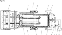
- FIG. 1 a is a baler 1 shown, which has a press ram 2, which is deliverable in the direction of a press room, not shown.
- a press ram 2 By the ram 2 isolated individual cargo, such as cardboard, grass or the like to be compressed to a compact bale to require a small footprint in their disposal or storage.
- the ram 2 is delivered by two pairs I and II of a total of four printing cylinders 3, 4, 5 and 6.
- the first pair I of the impression cylinders 3 and 4 are aligned parallel to one another and arranged between a frame 10 of the baler 1 and a carriage 11 movably mounted in the baling press 1.
- Each of the printing cylinder 3, 4, 5 and 6 consists of a telescopically extendable piston 9, the direction of movement is indicated by the reference numeral 22.
- the pistons 9 of the respective impression cylinders 3, 4, 5 and 6 are thus moved back and forth in synchronism with one another so that, on the one hand, the carriage 11 and, on the other hand, the ram 2 are moved back and forth in the feed direction 22.
- a medium 15 is provided, for example air, hydraulic or a gas mixture which is mounted in a container 23.
- a medium 15 is provided, for example air, hydraulic or a gas mixture which is mounted in a container 23.
- the pump 14 is driven by means of a motor 13.
- These drive means are identified by the reference numeral 12; for the expert it is of course, to replace the presented drive means 12 by other mechanical or electrical drive means to convey the medium 15 through the conduits 16.
- the medium 15 is thus pressed out of the container 23 through the lines 16 in the press ram 2 opposite pressure chambers 7 of the respective impression cylinder 3, 4, 5 and 6, so that thereby, as will be explained in detail below, the piston 9 is pressed in the direction of the pressing space.
- the lines 16, which open into the pressure chamber 7 of the respective pressure cylinder 3, 4, 5 and 6, form a first delivery circuit A.
- a second return circuit B which opens into the pressure chambers 8 of the respective pressure cylinders 3, 4, 5 and 6.
- the inlet openings in the pressure chambers 7 of the respective pressure cylinder 3, 4, 5 and 6 are marked with the letter A and a natural number, in such a way that the number used represents the order of the delivery cycle A. This therefore means that the medium 15 is first pressed by the pump 13 into the inlet opening A1 of the first pressure cylinder 3 of the first pair I.
- the piston 9 is designed as a tube.
- the outwardly projecting free end of the piston 9 is closed, so that the medium 15 flows through the inlet opening A1 and moves the piston 9 in the direction of the ram 2.
- an outlet opening A2 located in the region of the free end of the piston 9, which is connected via one of the lines 16 to the inlet opening A3 of the second pressure cylinder 4 of the first pair I.
- the medium 15 flows into the pressure chamber 7 of the second pressure cylinder 4 a.
- the piston 9 used there has, in the region of the pressure chamber 7, a plate 17, through which the inner tube piece of the piston 9 is closed in the direction of the pressure chamber 7.
- FIG. 1 a is also apparent that the first pressure cylinder 3 of the first pair I is connected via a further line 16 with inlet openings A3 and A4 of the pressure cylinder 5 and 6 of the second pair II, so that all of the four provided pressure cylinder 3, by the inflowing medium 15, 4, 5 and 6 are filled and is moved synchronously by the resulting pressure in the space 7 overpressure of the piston 9 from the impression cylinder 3, 4, 5 and 6.
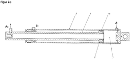
- the return circuit B is provided.
- FIG. 2a shows that between the outer circumference of the piston 9 and the inner wall of the printing cylinder 3, an annular air gap is present, which is used as a pressure chamber 8.
- the medium 15 is first filled into an opening into the pressure chamber 8 inlet opening B1, so that the piston 9 is moved in the direction of the pressure chamber 7.
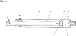
- FIG. 2b It is shown that the printing cylinder 4 constructed essentially identically can be filled with the medium 15 through an inlet opening B2. Moreover, the piston 9 in the region of the plate 17 has a plurality of bores 19, through which the medium 15 flows into the interior of the piston 9 and flows out of an area opposite the plate 17 through an outlet opening B3.
- the outlet port B3 is connected to the inlet ports B4 and B5 of the pressure cylinders 5 and 6 of the second pair II by two lines 16, so that the pistons 9 of the pressure cylinders 5 and 6 are moved back simultaneously with the piston 9 of the pressure cylinders 3 and 4.
- the lines 16 are firmly connected to the respective pressure cylinders 3, 4, 5 and 6, so that between the lines 16 the pressure cylinders, 3, 4, 5 and 6, no relative movement takes place.
- the blocking or opening of the lines 16 for the delivery circuit A and the return hollow circuit B are switched by means of control valves 24.
- the return circuit B for the passage of the medium 15 is closed in the pressure chambers 8; however, the medium 15 present in the pressure chambers 8 can flow back out of these via the lines 16 into the container 23 and through the control valves 24 opened in this direction.
- the delivery circuit A is closed by means of the control valves 24 and the medium 15 is pressed into the return circuit B by means of the pump 13.
- the present in the pressure chambers 7 medium 15 passes through the control valves 24 in the container 23. Consequently, an uncomplicated and fast operation of the baler 1 is reached.
- the space of the baler 1 and their available stroke are not affected by the constructive measures to promote the medium 15.
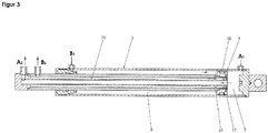
- the impression cylinder 3 is according to FIG. 3 constructed so that the inlet opening A1 opens into the pressure chamber 7, however, the piston 9 is configured zwewandig, so that the filled medium 15 first flows from the pressure chamber 7 through the interior of the piston 9 in the direction of the free outwardly projecting end and from a in the piston 9 incorporated outlet opening A2 flows out.
- the outlet port A2 is connected to the inlet port A3 of the second pressure cylinder 5 via one of the conduits 16.
- an inlet opening B1 is first provided in the first pressure cylinder 3, which opens into an annular gap extending between the inner wall of the pressure cylinder 3 and the outer wall of the piston 9 and accordingly Pressure chamber 8 forms.
- the pressure chamber 8 is separated from the pressure chamber 7 by means of one of the seals 18.
- a through hole 21 is incorporated, which opens into a passageway 20 which extends between the outer and the inner wall of the piston 9.
- an outlet opening B2 is present, which is connected to one of the lines 16 with the inlet opening B3 of the second pressure cylinder 5.
- both two pressure cylinders 3 and 5 arranged one behind the other as well as the conveying of the medium 15 can be accomplished by two pairs I, II of four pressure cylinders 3, 4, 5 and 6.
- Each of the impression cylinders 3, 4, 5 and 6 explained FIGS. 1a to 3 can have any length and cross-sectional shape.
- the geometric relationships of the printing cylinders 3, 4, 5 and 6 depend essentially on the pressure forces that are necessary to compress the filled in the press room cargo.
Landscapes
- Engineering & Computer Science (AREA)
- Mechanical Engineering (AREA)
- Physics & Mathematics (AREA)
- Fluid Mechanics (AREA)
- General Engineering & Computer Science (AREA)
- Inking, Control Or Cleaning Of Printing Machines (AREA)
- Auxiliary Devices For And Details Of Packaging Control (AREA)
Priority Applications (2)
| Application Number | Priority Date | Filing Date | Title |
|---|---|---|---|
| PL13184233T PL2848397T3 (pl) | 2013-09-13 | 2013-09-13 | Prasa do belowania |
| EP13184233.8A EP2848397B1 (de) | 2013-09-13 | 2013-09-13 | Ballenpresse |
Applications Claiming Priority (1)
| Application Number | Priority Date | Filing Date | Title |
|---|---|---|---|
| EP13184233.8A EP2848397B1 (de) | 2013-09-13 | 2013-09-13 | Ballenpresse |
Publications (2)
| Publication Number | Publication Date |
|---|---|
| EP2848397A1 EP2848397A1 (de) | 2015-03-18 |
| EP2848397B1 true EP2848397B1 (de) | 2017-05-10 |
Family
ID=49209239
Family Applications (1)
| Application Number | Title | Priority Date | Filing Date |
|---|---|---|---|
| EP13184233.8A Not-in-force EP2848397B1 (de) | 2013-09-13 | 2013-09-13 | Ballenpresse |
Country Status (2)
| Country | Link |
|---|---|
| EP (1) | EP2848397B1 (pl) |
| PL (1) | PL2848397T3 (pl) |
Cited By (2)
| Publication number | Priority date | Publication date | Assignee | Title |
|---|---|---|---|---|
| EP3620296A1 (de) | 2018-09-10 | 2020-03-11 | Maschinenfabrik Bermatingen GmbH & Co. KG | Ballenpresse sowie steuerverfahren für eine solche |
| DE102024123686A1 (de) * | 2024-08-20 | 2026-02-26 | Herbert Kannegiesser Gmbh | Entwässerungspresse zum Entwässern von Wäsche |
Families Citing this family (2)
| Publication number | Priority date | Publication date | Assignee | Title |
|---|---|---|---|---|
| CN109664538A (zh) * | 2019-02-15 | 2019-04-23 | 南通海利特橡塑机械有限公司 | 一种新型四柱液压压力机 |
| EP4349582A1 (de) * | 2022-10-07 | 2024-04-10 | HSM GmbH + Co. KG | Ballenpresse und verfahren zum betrieb einer solchen |
Family Cites Families (10)
| Publication number | Priority date | Publication date | Assignee | Title |
|---|---|---|---|---|
| GB1064061A (en) * | 1962-12-19 | 1967-04-05 | Fletcer And Stewart Ltd | Baling press |
| US3384007A (en) * | 1967-08-09 | 1968-05-21 | Compactor Corp | Waster compacting device |
| DE2115353A1 (de) * | 1971-03-30 | 1972-12-07 | Jacobs, Max, 5650 Solingen-Wald | Hydraulische Vorrichtung zum Heben und Senken von Lasten |
| US3802337A (en) * | 1971-10-06 | 1974-04-09 | Gen Compactor Of Quebec Ltd | Refuse compactor |
| DE2237453A1 (de) * | 1972-07-29 | 1974-02-07 | Karl Heinz Stein | Teleskopzylinder mit hydraulisch bewirktem vor- und rueckschub fuer kranausleger u. dgl |
| US3802336A (en) * | 1972-11-24 | 1974-04-09 | Carrier Corp | Refuse compacting device |
| DE8717589U1 (de) * | 1987-10-13 | 1989-05-03 | Maschinenfabrik Bermatingen GmbH & Co, 7775 Bermatingen | Ballenpresse |
| DE9301899U1 (de) * | 1993-02-11 | 1993-07-29 | Langerbein-Scharf GmbH & Co. KG, 4700 Hamm | Hydraulische Betätigungsvorrichtung mit zumindest zwei gekoppelten Betätigungselementen |
| FR2725250B1 (fr) * | 1994-09-29 | 1996-12-20 | Fdi Sambron | Dispositif comprenant au moins trois elements mobiles en coulissement et actionnes par des verins |
| DE102009053134C5 (de) | 2009-11-05 | 2018-01-25 | Maschinenfabrik Bermatingen Gmbh & Co. Kg | Ballenpresse |
-
2013
- 2013-09-13 EP EP13184233.8A patent/EP2848397B1/de not_active Not-in-force
- 2013-09-13 PL PL13184233T patent/PL2848397T3/pl unknown
Cited By (2)
| Publication number | Priority date | Publication date | Assignee | Title |
|---|---|---|---|---|
| EP3620296A1 (de) | 2018-09-10 | 2020-03-11 | Maschinenfabrik Bermatingen GmbH & Co. KG | Ballenpresse sowie steuerverfahren für eine solche |
| DE102024123686A1 (de) * | 2024-08-20 | 2026-02-26 | Herbert Kannegiesser Gmbh | Entwässerungspresse zum Entwässern von Wäsche |
Also Published As
| Publication number | Publication date |
|---|---|
| EP2848397A1 (de) | 2015-03-18 |
| PL2848397T3 (pl) | 2017-09-29 |
Similar Documents
| Publication | Publication Date | Title |
|---|---|---|
| EP3620296B1 (de) | Ballenpresse sowie steuerverfahren für eine solche | |
| EP2848397B1 (de) | Ballenpresse | |
| EP2773471B1 (de) | Strang- und rohrpresse bzw. metallstrangpresse | |
| DE3834610C2 (pl) | ||
| DE102010013107A1 (de) | Ventil zum alternierenden Befüllen zweier Arbeitsräume eines Kolben-Zylinder-Systems einer Pumpe | |
| DE102019204874A1 (de) | Umschaltvorrichtung und Schmierpumpe | |
| DE2631479A1 (de) | Arbeitskolbenvorrichtung | |
| DE1403973A1 (de) | Dosierungspumpe | |
| DE10354952A1 (de) | Antriebsvorrichtung | |
| DE102011100632A1 (de) | Kolben-Zylinder-Einheit | |
| DE102011114241B4 (de) | Hydraulische Antriebsvorrichtung, Hydraulische Endstufe eines hydraulischen Servo-Regelventils, Servo-Regelventil und Pulverpresse | |
| DE102009037959A1 (de) | Arbeitszylinder mit vier mechanischen Stopppositionen | |
| EP2952800B1 (de) | Schmiermittelpumpe | |
| DE1503334A1 (de) | Hydraulische Vorrichtung zum Erzeugen einer hin- und hergehenden Bewegung | |
| DE3911278C2 (de) | Plunger-Pumpe | |
| DE3642695C2 (de) | Zylinderantrieb | |
| DE102023000817A1 (de) | Verfahren zum Ansteuern eines fluidischen Aktors nebst Vorrichtung zum Durchführen des Verfahrens | |
| DE1016194B (de) | Hydraulische Hubvorrichtung fuer Stapelvorrichtungen mit teleskopartig ausziehbarem Hubmast | |
| EP3601800B1 (de) | Mehrstufiger verdichter | |
| EP0718040B1 (de) | Lackförderpumpe | |
| DE3033739A1 (de) | Druckuebersetzer zur hoechstdruckerzeugung | |
| DE1752761B2 (de) | Überlastsicherung für eine Vorrichtung zur Herstellung nahtloser becherförmiger Behälter durch Ziehen | |
| EP4349582A1 (de) | Ballenpresse und verfahren zum betrieb einer solchen | |
| DE3150976A1 (de) | Druckluftgetriebene doppelmembranpumpe | |
| DE10051042C2 (de) | Antriebszylinder für Stanzen, Prägemaschinen, Pressen und dergleichen |
Legal Events
| Date | Code | Title | Description |
|---|---|---|---|
| PUAI | Public reference made under article 153(3) epc to a published international application that has entered the european phase |
Free format text: ORIGINAL CODE: 0009012 |
|
| 17P | Request for examination filed |
Effective date: 20130913 |
|
| AK | Designated contracting states |
Kind code of ref document: A1 Designated state(s): AL AT BE BG CH CY CZ DE DK EE ES FI FR GB GR HR HU IE IS IT LI LT LU LV MC MK MT NL NO PL PT RO RS SE SI SK SM TR |
|
| AX | Request for extension of the european patent |
Extension state: BA ME |
|
| R17P | Request for examination filed (corrected) |
Effective date: 20150910 |
|
| RBV | Designated contracting states (corrected) |
Designated state(s): AL AT BE BG CH CY CZ DE DK EE ES FI FR GB GR HR HU IE IS IT LI LT LU LV MC MK MT NL NO PL PT RO RS SE SI SK SM TR |
|
| REG | Reference to a national code |
Ref country code: DE Ref legal event code: R079 Ref document number: 502013007201 Country of ref document: DE Free format text: PREVIOUS MAIN CLASS: B30B0001340000 Ipc: F15B0011200000 |
|
| GRAP | Despatch of communication of intention to grant a patent |
Free format text: ORIGINAL CODE: EPIDOSNIGR1 |
|
| RIC1 | Information provided on ipc code assigned before grant |
Ipc: F15B 15/14 20060101ALI20161129BHEP Ipc: B30B 1/34 20060101ALI20161129BHEP Ipc: F15B 11/20 20060101AFI20161129BHEP Ipc: B30B 1/36 20060101ALI20161129BHEP Ipc: B30B 9/30 20060101ALI20161129BHEP |
|
| INTG | Intention to grant announced |
Effective date: 20161222 |
|
| GRAS | Grant fee paid |
Free format text: ORIGINAL CODE: EPIDOSNIGR3 |
|
| GRAA | (expected) grant |
Free format text: ORIGINAL CODE: 0009210 |
|
| AK | Designated contracting states |
Kind code of ref document: B1 Designated state(s): AL AT BE BG CH CY CZ DE DK EE ES FI FR GB GR HR HU IE IS IT LI LT LU LV MC MK MT NL NO PL PT RO RS SE SI SK SM TR |
|
| REG | Reference to a national code |
Ref country code: GB Ref legal event code: FG4D Free format text: NOT ENGLISH |
|
| REG | Reference to a national code |
Ref country code: AT Ref legal event code: REF Ref document number: 892656 Country of ref document: AT Kind code of ref document: T Effective date: 20170515 Ref country code: CH Ref legal event code: EP |
|
| REG | Reference to a national code |
Ref country code: IE Ref legal event code: FG4D Free format text: LANGUAGE OF EP DOCUMENT: GERMAN |
|
| REG | Reference to a national code |
Ref country code: DE Ref legal event code: R096 Ref document number: 502013007201 Country of ref document: DE |
|
| REG | Reference to a national code |
Ref country code: NL Ref legal event code: MP Effective date: 20170510 |
|
| REG | Reference to a national code |
Ref country code: LT Ref legal event code: MG4D Ref country code: FR Ref legal event code: PLFP Year of fee payment: 5 |
|
| PG25 | Lapsed in a contracting state [announced via postgrant information from national office to epo] |
Ref country code: ES Free format text: LAPSE BECAUSE OF FAILURE TO SUBMIT A TRANSLATION OF THE DESCRIPTION OR TO PAY THE FEE WITHIN THE PRESCRIBED TIME-LIMIT Effective date: 20170510 Ref country code: LT Free format text: LAPSE BECAUSE OF FAILURE TO SUBMIT A TRANSLATION OF THE DESCRIPTION OR TO PAY THE FEE WITHIN THE PRESCRIBED TIME-LIMIT Effective date: 20170510 Ref country code: FI Free format text: LAPSE BECAUSE OF FAILURE TO SUBMIT A TRANSLATION OF THE DESCRIPTION OR TO PAY THE FEE WITHIN THE PRESCRIBED TIME-LIMIT Effective date: 20170510 Ref country code: HR Free format text: LAPSE BECAUSE OF FAILURE TO SUBMIT A TRANSLATION OF THE DESCRIPTION OR TO PAY THE FEE WITHIN THE PRESCRIBED TIME-LIMIT Effective date: 20170510 Ref country code: NO Free format text: LAPSE BECAUSE OF FAILURE TO SUBMIT A TRANSLATION OF THE DESCRIPTION OR TO PAY THE FEE WITHIN THE PRESCRIBED TIME-LIMIT Effective date: 20170810 Ref country code: GR Free format text: LAPSE BECAUSE OF FAILURE TO SUBMIT A TRANSLATION OF THE DESCRIPTION OR TO PAY THE FEE WITHIN THE PRESCRIBED TIME-LIMIT Effective date: 20170811 |
|
| PG25 | Lapsed in a contracting state [announced via postgrant information from national office to epo] |
Ref country code: BG Free format text: LAPSE BECAUSE OF FAILURE TO SUBMIT A TRANSLATION OF THE DESCRIPTION OR TO PAY THE FEE WITHIN THE PRESCRIBED TIME-LIMIT Effective date: 20170810 Ref country code: RS Free format text: LAPSE BECAUSE OF FAILURE TO SUBMIT A TRANSLATION OF THE DESCRIPTION OR TO PAY THE FEE WITHIN THE PRESCRIBED TIME-LIMIT Effective date: 20170510 Ref country code: LV Free format text: LAPSE BECAUSE OF FAILURE TO SUBMIT A TRANSLATION OF THE DESCRIPTION OR TO PAY THE FEE WITHIN THE PRESCRIBED TIME-LIMIT Effective date: 20170510 Ref country code: NL Free format text: LAPSE BECAUSE OF FAILURE TO SUBMIT A TRANSLATION OF THE DESCRIPTION OR TO PAY THE FEE WITHIN THE PRESCRIBED TIME-LIMIT Effective date: 20170510 Ref country code: IS Free format text: LAPSE BECAUSE OF FAILURE TO SUBMIT A TRANSLATION OF THE DESCRIPTION OR TO PAY THE FEE WITHIN THE PRESCRIBED TIME-LIMIT Effective date: 20170910 Ref country code: SE Free format text: LAPSE BECAUSE OF FAILURE TO SUBMIT A TRANSLATION OF THE DESCRIPTION OR TO PAY THE FEE WITHIN THE PRESCRIBED TIME-LIMIT Effective date: 20170510 |
|
| PG25 | Lapsed in a contracting state [announced via postgrant information from national office to epo] |
Ref country code: CZ Free format text: LAPSE BECAUSE OF FAILURE TO SUBMIT A TRANSLATION OF THE DESCRIPTION OR TO PAY THE FEE WITHIN THE PRESCRIBED TIME-LIMIT Effective date: 20170510 Ref country code: DK Free format text: LAPSE BECAUSE OF FAILURE TO SUBMIT A TRANSLATION OF THE DESCRIPTION OR TO PAY THE FEE WITHIN THE PRESCRIBED TIME-LIMIT Effective date: 20170510 Ref country code: EE Free format text: LAPSE BECAUSE OF FAILURE TO SUBMIT A TRANSLATION OF THE DESCRIPTION OR TO PAY THE FEE WITHIN THE PRESCRIBED TIME-LIMIT Effective date: 20170510 Ref country code: RO Free format text: LAPSE BECAUSE OF FAILURE TO SUBMIT A TRANSLATION OF THE DESCRIPTION OR TO PAY THE FEE WITHIN THE PRESCRIBED TIME-LIMIT Effective date: 20170510 Ref country code: SK Free format text: LAPSE BECAUSE OF FAILURE TO SUBMIT A TRANSLATION OF THE DESCRIPTION OR TO PAY THE FEE WITHIN THE PRESCRIBED TIME-LIMIT Effective date: 20170510 |
|
| REG | Reference to a national code |
Ref country code: DE Ref legal event code: R097 Ref document number: 502013007201 Country of ref document: DE |
|
| PG25 | Lapsed in a contracting state [announced via postgrant information from national office to epo] |
Ref country code: SM Free format text: LAPSE BECAUSE OF FAILURE TO SUBMIT A TRANSLATION OF THE DESCRIPTION OR TO PAY THE FEE WITHIN THE PRESCRIBED TIME-LIMIT Effective date: 20170510 |
|
| PLBE | No opposition filed within time limit |
Free format text: ORIGINAL CODE: 0009261 |
|
| STAA | Information on the status of an ep patent application or granted ep patent |
Free format text: STATUS: NO OPPOSITION FILED WITHIN TIME LIMIT |
|
| 26N | No opposition filed |
Effective date: 20180213 |
|
| REG | Reference to a national code |
Ref country code: CH Ref legal event code: PL |
|
| PG25 | Lapsed in a contracting state [announced via postgrant information from national office to epo] |
Ref country code: MC Free format text: LAPSE BECAUSE OF FAILURE TO SUBMIT A TRANSLATION OF THE DESCRIPTION OR TO PAY THE FEE WITHIN THE PRESCRIBED TIME-LIMIT Effective date: 20170510 Ref country code: SI Free format text: LAPSE BECAUSE OF FAILURE TO SUBMIT A TRANSLATION OF THE DESCRIPTION OR TO PAY THE FEE WITHIN THE PRESCRIBED TIME-LIMIT Effective date: 20170510 |
|
| REG | Reference to a national code |
Ref country code: IE Ref legal event code: MM4A |
|
| REG | Reference to a national code |
Ref country code: BE Ref legal event code: MM Effective date: 20170930 |
|
| PG25 | Lapsed in a contracting state [announced via postgrant information from national office to epo] |
Ref country code: LU Free format text: LAPSE BECAUSE OF NON-PAYMENT OF DUE FEES Effective date: 20170913 |
|
| PG25 | Lapsed in a contracting state [announced via postgrant information from national office to epo] |
Ref country code: LI Free format text: LAPSE BECAUSE OF NON-PAYMENT OF DUE FEES Effective date: 20170930 Ref country code: IE Free format text: LAPSE BECAUSE OF NON-PAYMENT OF DUE FEES Effective date: 20170913 Ref country code: CH Free format text: LAPSE BECAUSE OF NON-PAYMENT OF DUE FEES Effective date: 20170930 |
|
| PG25 | Lapsed in a contracting state [announced via postgrant information from national office to epo] |
Ref country code: BE Free format text: LAPSE BECAUSE OF NON-PAYMENT OF DUE FEES Effective date: 20170930 |
|
| REG | Reference to a national code |
Ref country code: FR Ref legal event code: PLFP Year of fee payment: 6 |
|
| PG25 | Lapsed in a contracting state [announced via postgrant information from national office to epo] |
Ref country code: MT Free format text: LAPSE BECAUSE OF FAILURE TO SUBMIT A TRANSLATION OF THE DESCRIPTION OR TO PAY THE FEE WITHIN THE PRESCRIBED TIME-LIMIT Effective date: 20170510 |
|
| PG25 | Lapsed in a contracting state [announced via postgrant information from national office to epo] |
Ref country code: HU Free format text: LAPSE BECAUSE OF FAILURE TO SUBMIT A TRANSLATION OF THE DESCRIPTION OR TO PAY THE FEE WITHIN THE PRESCRIBED TIME-LIMIT; INVALID AB INITIO Effective date: 20130913 |
|
| PG25 | Lapsed in a contracting state [announced via postgrant information from national office to epo] |
Ref country code: CY Free format text: LAPSE BECAUSE OF FAILURE TO SUBMIT A TRANSLATION OF THE DESCRIPTION OR TO PAY THE FEE WITHIN THE PRESCRIBED TIME-LIMIT Effective date: 20170510 |
|
| PG25 | Lapsed in a contracting state [announced via postgrant information from national office to epo] |
Ref country code: MK Free format text: LAPSE BECAUSE OF FAILURE TO SUBMIT A TRANSLATION OF THE DESCRIPTION OR TO PAY THE FEE WITHIN THE PRESCRIBED TIME-LIMIT Effective date: 20170510 |
|
| PG25 | Lapsed in a contracting state [announced via postgrant information from national office to epo] |
Ref country code: TR Free format text: LAPSE BECAUSE OF FAILURE TO SUBMIT A TRANSLATION OF THE DESCRIPTION OR TO PAY THE FEE WITHIN THE PRESCRIBED TIME-LIMIT Effective date: 20170510 |
|
| PG25 | Lapsed in a contracting state [announced via postgrant information from national office to epo] |
Ref country code: PT Free format text: LAPSE BECAUSE OF FAILURE TO SUBMIT A TRANSLATION OF THE DESCRIPTION OR TO PAY THE FEE WITHIN THE PRESCRIBED TIME-LIMIT Effective date: 20170510 |
|
| PG25 | Lapsed in a contracting state [announced via postgrant information from national office to epo] |
Ref country code: AL Free format text: LAPSE BECAUSE OF FAILURE TO SUBMIT A TRANSLATION OF THE DESCRIPTION OR TO PAY THE FEE WITHIN THE PRESCRIBED TIME-LIMIT Effective date: 20170510 |
|
| REG | Reference to a national code |
Ref country code: DE Ref legal event code: R082 Ref document number: 502013007201 Country of ref document: DE Representative=s name: GEITZ TRUCKENMUELLER LUCHT CHRIST PATENTANWAEL, DE Ref country code: DE Ref legal event code: R082 Ref document number: 502013007201 Country of ref document: DE Representative=s name: WEICKMANN & WEICKMANN PATENT- UND RECHTSANWAEL, DE |
|
| P01 | Opt-out of the competence of the unified patent court (upc) registered |
Effective date: 20230518 |
|
| REG | Reference to a national code |
Ref country code: DE Ref legal event code: R082 Ref document number: 502013007201 Country of ref document: DE Representative=s name: WEICKMANN & WEICKMANN PATENT- UND RECHTSANWAEL, DE Ref country code: DE Ref legal event code: R082 Ref document number: 502013007201 Country of ref document: DE |
|
| REG | Reference to a national code |
Ref country code: DE Ref legal event code: R082 Ref document number: 502013007201 Country of ref document: DE Representative=s name: WEICKMANN & WEICKMANN PATENT- UND RECHTSANWAEL, DE Ref country code: DE Ref legal event code: R081 Ref document number: 502013007201 Country of ref document: DE Owner name: HSM GMBH + CO. KG, DE Free format text: FORMER OWNER: MASCHINENFABRIK BERMATINGEN GMBH & CO. KG, 88697 BERMATINGEN, DE |
|
| PGFP | Annual fee paid to national office [announced via postgrant information from national office to epo] |
Ref country code: GB Payment date: 20230929 Year of fee payment: 11 Ref country code: AT Payment date: 20230927 Year of fee payment: 11 |
|
| PGFP | Annual fee paid to national office [announced via postgrant information from national office to epo] |
Ref country code: FR Payment date: 20230928 Year of fee payment: 11 |
|
| PGFP | Annual fee paid to national office [announced via postgrant information from national office to epo] |
Ref country code: IT Payment date: 20230926 Year of fee payment: 11 Ref country code: DE Payment date: 20230929 Year of fee payment: 11 |
|
| PGFP | Annual fee paid to national office [announced via postgrant information from national office to epo] |
Ref country code: PL Payment date: 20231011 Year of fee payment: 11 |
|
| REG | Reference to a national code |
Ref country code: DE Ref legal event code: R119 Ref document number: 502013007201 Country of ref document: DE |
|
| REG | Reference to a national code |
Ref country code: AT Ref legal event code: MM01 Ref document number: 892656 Country of ref document: AT Kind code of ref document: T Effective date: 20240913 |
|
| GBPC | Gb: european patent ceased through non-payment of renewal fee |
Effective date: 20240913 |
|
| PG25 | Lapsed in a contracting state [announced via postgrant information from national office to epo] |
Ref country code: DE Free format text: LAPSE BECAUSE OF NON-PAYMENT OF DUE FEES Effective date: 20250401 |
|
| PG25 | Lapsed in a contracting state [announced via postgrant information from national office to epo] |
Ref country code: GB Free format text: LAPSE BECAUSE OF NON-PAYMENT OF DUE FEES Effective date: 20240913 |
|
| PG25 | Lapsed in a contracting state [announced via postgrant information from national office to epo] |
Ref country code: IT Free format text: LAPSE BECAUSE OF NON-PAYMENT OF DUE FEES Effective date: 20240913 |
|
| PG25 | Lapsed in a contracting state [announced via postgrant information from national office to epo] |
Ref country code: FR Free format text: LAPSE BECAUSE OF NON-PAYMENT OF DUE FEES Effective date: 20240930 |
|
| PG25 | Lapsed in a contracting state [announced via postgrant information from national office to epo] |
Ref country code: AT Free format text: LAPSE BECAUSE OF NON-PAYMENT OF DUE FEES Effective date: 20240913 |
|
| PG25 | Lapsed in a contracting state [announced via postgrant information from national office to epo] |
Ref country code: PL Free format text: LAPSE BECAUSE OF NON-PAYMENT OF DUE FEES Effective date: 20240913 |