EP2848397B1 - Baling press - Google Patents
Baling press Download PDFInfo
- Publication number
- EP2848397B1 EP2848397B1 EP13184233.8A EP13184233A EP2848397B1 EP 2848397 B1 EP2848397 B1 EP 2848397B1 EP 13184233 A EP13184233 A EP 13184233A EP 2848397 B1 EP2848397 B1 EP 2848397B1
- Authority
- EP
- European Patent Office
- Prior art keywords
- pressure
- piston
- pressure cylinder
- cylinders
- space
- Prior art date
- Legal status (The legal status is an assumption and is not a legal conclusion. Google has not performed a legal analysis and makes no representation as to the accuracy of the status listed.)
- Not-in-force
Links
Images

Classifications
-
- B—PERFORMING OPERATIONS; TRANSPORTING
- B30—PRESSES
- B30B—PRESSES IN GENERAL
- B30B9/00—Presses specially adapted for particular purposes
- B30B9/30—Presses specially adapted for particular purposes for baling; Compression boxes therefor
- B30B9/3057—Fluid-driven presses
-
- B—PERFORMING OPERATIONS; TRANSPORTING
- B30—PRESSES
- B30B—PRESSES IN GENERAL
- B30B1/00—Presses, using a press ram, characterised by the features of the drive therefor, pressure being transmitted directly, or through simple thrust or tension members only, to the press ram or platen
- B30B1/32—Presses, using a press ram, characterised by the features of the drive therefor, pressure being transmitted directly, or through simple thrust or tension members only, to the press ram or platen by plungers under fluid pressure
- B30B1/34—Presses, using a press ram, characterised by the features of the drive therefor, pressure being transmitted directly, or through simple thrust or tension members only, to the press ram or platen by plungers under fluid pressure involving a plurality of plungers acting on the platen
-
- B—PERFORMING OPERATIONS; TRANSPORTING
- B30—PRESSES
- B30B—PRESSES IN GENERAL
- B30B1/00—Presses, using a press ram, characterised by the features of the drive therefor, pressure being transmitted directly, or through simple thrust or tension members only, to the press ram or platen
- B30B1/32—Presses, using a press ram, characterised by the features of the drive therefor, pressure being transmitted directly, or through simple thrust or tension members only, to the press ram or platen by plungers under fluid pressure
- B30B1/36—Presses, using a press ram, characterised by the features of the drive therefor, pressure being transmitted directly, or through simple thrust or tension members only, to the press ram or platen by plungers under fluid pressure having telescoping plungers
-
- F—MECHANICAL ENGINEERING; LIGHTING; HEATING; WEAPONS; BLASTING
- F15—FLUID-PRESSURE ACTUATORS; HYDRAULICS OR PNEUMATICS IN GENERAL
- F15B—SYSTEMS ACTING BY MEANS OF FLUIDS IN GENERAL; FLUID-PRESSURE ACTUATORS, e.g. SERVOMOTORS; DETAILS OF FLUID-PRESSURE SYSTEMS, NOT OTHERWISE PROVIDED FOR
- F15B11/00—Servomotor systems without provision for follow-up action; Circuits therefor
- F15B11/16—Servomotor systems without provision for follow-up action; Circuits therefor with two or more servomotors
- F15B11/20—Servomotor systems without provision for follow-up action; Circuits therefor with two or more servomotors controlling several interacting or sequentially-operating members
-
- F—MECHANICAL ENGINEERING; LIGHTING; HEATING; WEAPONS; BLASTING
- F15—FLUID-PRESSURE ACTUATORS; HYDRAULICS OR PNEUMATICS IN GENERAL
- F15B—SYSTEMS ACTING BY MEANS OF FLUIDS IN GENERAL; FLUID-PRESSURE ACTUATORS, e.g. SERVOMOTORS; DETAILS OF FLUID-PRESSURE SYSTEMS, NOT OTHERWISE PROVIDED FOR
- F15B15/00—Fluid-actuated devices for displacing a member from one position to another; Gearing associated therewith
- F15B15/08—Characterised by the construction of the motor unit
- F15B15/14—Characterised by the construction of the motor unit of the straight-cylinder type
- F15B15/1423—Component parts; Constructional details
- F15B15/1457—Piston rods
-
- F—MECHANICAL ENGINEERING; LIGHTING; HEATING; WEAPONS; BLASTING
- F15—FLUID-PRESSURE ACTUATORS; HYDRAULICS OR PNEUMATICS IN GENERAL
- F15B—SYSTEMS ACTING BY MEANS OF FLUIDS IN GENERAL; FLUID-PRESSURE ACTUATORS, e.g. SERVOMOTORS; DETAILS OF FLUID-PRESSURE SYSTEMS, NOT OTHERWISE PROVIDED FOR
- F15B15/00—Fluid-actuated devices for displacing a member from one position to another; Gearing associated therewith
- F15B15/08—Characterised by the construction of the motor unit
- F15B15/14—Characterised by the construction of the motor unit of the straight-cylinder type
- F15B15/149—Fluid interconnections, e.g. fluid connectors, passages
Definitions
- the invention relates to a baler according to the preambles of claims 1 and 8.
- Such a baling press which initially consists of a first pair of pressure cylinders, which are installed between a frame of the baler and a mounted in the baler carriage. Between the carriage and a retractable into the press chamber a second pair of pressure cylinders is arranged so that the axial extent of the baler can be limited to a minimum and the stroke optimally designed by the ram due to the two pairs of pressure cylinders connected in series is because the stroke movement of the ram is increased by the two pairs of pressure cylinders compared with only a pair of pressure cylinders.
- the printing cylinders each consist of a telescopically extendable piston, which is attached to the carriage or the press ram and are separated by the two pressure chambers in the printing cylinder.
- balers have been proven for the pressing of cargo, such as cardboard, grass or the like.
- those for the operation of Pistons of the pressure cylinder necessary media through pipes in the respective pressure chambers of the pressure cylinder to promote reciprocation of the piston.
- These pipes are usually configured flexurally elastic and arranged meandering along the respective pressure cylinders, so that when extending the respective pistons, the pipelines travel along the strokes of the pistons.
- From the DE 2115353 is a hydraulic device for lifting and lowering against loads known. Two pressure cylinders connected in series are connected to each other by means of an integrated piping system.
- Such flexurally elastic lines have multiple disadvantages, because on the one hand, the stroke, the pressure cylinders can cover the necessary lines, limited because the lines can only have a certain predetermined length and on the other hand, the cross sections of the lines used are not sized so large be that a significant volume flow of a medium can be promoted through the lines, because the larger the cross-sections of the lines are sized, the more rigid they are.
- the pressure from the cylinders Provided compressive force acting on the baler of the baler, in comparison with the known balers is at least the same size, that the stroke, put back the pistons of the printing cylinder is identical to the stroke of the known balers and that at the same time the required space
- the baler can be kept constant in comparison with known balers.
- a second conduit system is provided, that the conduit systems are separated from each other and are each connected to the drive means, that the respective conduit system is integrated in the respective pressure cylinder and that the connection between the pressure cylinders takes place through the lines which are fixedly connected to the respective pressure cylinders, no relative displacement or movement arises between the lines and the movements of the pressure cylinders.
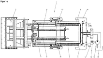
- FIG. 1 a is a baler 1 shown, which has a press ram 2, which is deliverable in the direction of a press room, not shown.
- a press ram 2 By the ram 2 isolated individual cargo, such as cardboard, grass or the like to be compressed to a compact bale to require a small footprint in their disposal or storage.
- the ram 2 is delivered by two pairs I and II of a total of four printing cylinders 3, 4, 5 and 6.
- the first pair I of the impression cylinders 3 and 4 are aligned parallel to one another and arranged between a frame 10 of the baler 1 and a carriage 11 movably mounted in the baling press 1.
- Each of the printing cylinder 3, 4, 5 and 6 consists of a telescopically extendable piston 9, the direction of movement is indicated by the reference numeral 22.
- the pistons 9 of the respective impression cylinders 3, 4, 5 and 6 are thus moved back and forth in synchronism with one another so that, on the one hand, the carriage 11 and, on the other hand, the ram 2 are moved back and forth in the feed direction 22.
- a medium 15 is provided, for example air, hydraulic or a gas mixture which is mounted in a container 23.
- a medium 15 is provided, for example air, hydraulic or a gas mixture which is mounted in a container 23.
- the pump 14 is driven by means of a motor 13.
- These drive means are identified by the reference numeral 12; for the expert it is of course, to replace the presented drive means 12 by other mechanical or electrical drive means to convey the medium 15 through the conduits 16.
- the medium 15 is thus pressed out of the container 23 through the lines 16 in the press ram 2 opposite pressure chambers 7 of the respective impression cylinder 3, 4, 5 and 6, so that thereby, as will be explained in detail below, the piston 9 is pressed in the direction of the pressing space.
- the lines 16, which open into the pressure chamber 7 of the respective pressure cylinder 3, 4, 5 and 6, form a first delivery circuit A.
- a second return circuit B which opens into the pressure chambers 8 of the respective pressure cylinders 3, 4, 5 and 6.
- the inlet openings in the pressure chambers 7 of the respective pressure cylinder 3, 4, 5 and 6 are marked with the letter A and a natural number, in such a way that the number used represents the order of the delivery cycle A. This therefore means that the medium 15 is first pressed by the pump 13 into the inlet opening A1 of the first pressure cylinder 3 of the first pair I.
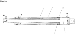
- the piston 9 is designed as a tube.
- the outwardly projecting free end of the piston 9 is closed, so that the medium 15 flows through the inlet opening A1 and moves the piston 9 in the direction of the ram 2.
- an outlet opening A2 located in the region of the free end of the piston 9, which is connected via one of the lines 16 to the inlet opening A3 of the second pressure cylinder 4 of the first pair I.
- the medium 15 flows into the pressure chamber 7 of the second pressure cylinder 4 a.
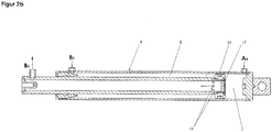
- the piston 9 used there has, in the region of the pressure chamber 7, a plate 17, through which the inner tube piece of the piston 9 is closed in the direction of the pressure chamber 7.
- FIG. 1 a is also apparent that the first pressure cylinder 3 of the first pair I is connected via a further line 16 with inlet openings A3 and A4 of the pressure cylinder 5 and 6 of the second pair II, so that all of the four provided pressure cylinder 3, by the inflowing medium 15, 4, 5 and 6 are filled and is moved synchronously by the resulting pressure in the space 7 overpressure of the piston 9 from the impression cylinder 3, 4, 5 and 6.
- the return circuit B is provided.
- FIG. 2a shows that between the outer circumference of the piston 9 and the inner wall of the printing cylinder 3, an annular air gap is present, which is used as a pressure chamber 8.
- the medium 15 is first filled into an opening into the pressure chamber 8 inlet opening B1, so that the piston 9 is moved in the direction of the pressure chamber 7.
- FIG. 2b It is shown that the printing cylinder 4 constructed essentially identically can be filled with the medium 15 through an inlet opening B2. Moreover, the piston 9 in the region of the plate 17 has a plurality of bores 19, through which the medium 15 flows into the interior of the piston 9 and flows out of an area opposite the plate 17 through an outlet opening B3.
- the outlet port B3 is connected to the inlet ports B4 and B5 of the pressure cylinders 5 and 6 of the second pair II by two lines 16, so that the pistons 9 of the pressure cylinders 5 and 6 are moved back simultaneously with the piston 9 of the pressure cylinders 3 and 4.
- the lines 16 are firmly connected to the respective pressure cylinders 3, 4, 5 and 6, so that between the lines 16 the pressure cylinders, 3, 4, 5 and 6, no relative movement takes place.
- the blocking or opening of the lines 16 for the delivery circuit A and the return hollow circuit B are switched by means of control valves 24.
- the return circuit B for the passage of the medium 15 is closed in the pressure chambers 8; however, the medium 15 present in the pressure chambers 8 can flow back out of these via the lines 16 into the container 23 and through the control valves 24 opened in this direction.
- the delivery circuit A is closed by means of the control valves 24 and the medium 15 is pressed into the return circuit B by means of the pump 13.
- the present in the pressure chambers 7 medium 15 passes through the control valves 24 in the container 23. Consequently, an uncomplicated and fast operation of the baler 1 is reached.
- the space of the baler 1 and their available stroke are not affected by the constructive measures to promote the medium 15.
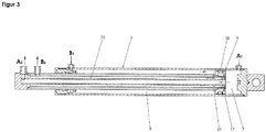
- the impression cylinder 3 is according to FIG. 3 constructed so that the inlet opening A1 opens into the pressure chamber 7, however, the piston 9 is configured zwewandig, so that the filled medium 15 first flows from the pressure chamber 7 through the interior of the piston 9 in the direction of the free outwardly projecting end and from a in the piston 9 incorporated outlet opening A2 flows out.
- the outlet port A2 is connected to the inlet port A3 of the second pressure cylinder 5 via one of the conduits 16.
- an inlet opening B1 is first provided in the first pressure cylinder 3, which opens into an annular gap extending between the inner wall of the pressure cylinder 3 and the outer wall of the piston 9 and accordingly Pressure chamber 8 forms.
- the pressure chamber 8 is separated from the pressure chamber 7 by means of one of the seals 18.
- a through hole 21 is incorporated, which opens into a passageway 20 which extends between the outer and the inner wall of the piston 9.
- an outlet opening B2 is present, which is connected to one of the lines 16 with the inlet opening B3 of the second pressure cylinder 5.
- both two pressure cylinders 3 and 5 arranged one behind the other as well as the conveying of the medium 15 can be accomplished by two pairs I, II of four pressure cylinders 3, 4, 5 and 6.
- Each of the impression cylinders 3, 4, 5 and 6 explained FIGS. 1a to 3 can have any length and cross-sectional shape.
- the geometric relationships of the printing cylinders 3, 4, 5 and 6 depend essentially on the pressure forces that are necessary to compress the filled in the press room cargo.
Landscapes
- Engineering & Computer Science (AREA)
- Mechanical Engineering (AREA)
- Physics & Mathematics (AREA)
- Fluid Mechanics (AREA)
- General Engineering & Computer Science (AREA)
- Auxiliary Devices For And Details Of Packaging Control (AREA)
- Inking, Control Or Cleaning Of Printing Machines (AREA)
Description
Die Erfindung bezieht sich auf eine Ballenpresse nach den Oberbegriffen der Patentansprüche 1 und 8.The invention relates to a baler according to the preambles of
Aus der
Durch die
Solche Ballenpressen haben sich zur Verpressung von Stückgut, beispielsweise Kartonage, Gras oder dgl., in der Praxis bewährt. Allerdings sind die zur Betätigung der Kolben der Druckzylinder notwendigen Medien durch Rohrleitungen in die jeweiligen Druckräume der Druckzylinder zur Hin- und Herbewegung der Kolben zu fördern. Diese Rohrleitungen sind üblicherweise biegeelastisch ausgestaltet und mäanderförmig entlang den jeweiligen Druckzylindern angeordnet, so dass beim Ausfahren der jeweilige Kolben die Rohrleitungen die Hubbewegungen der Kolben mitfahren. Aus der
Solche biegeelastischen Leitungen weisen mehrfache Nachteile auf, denn zum einen ist der Hubweg, den die Druckzylinder zurücklegen können durch die notwendigen Leitungen, begrenzt, da die Leitungen lediglich eine gewisse vorgegebene Länge aufweisen können und zum anderen können die Querschnitte der verwendeten Leitungen nicht derart groß bemessen werden, dass ein erheblicher Volumenstrom eines Mediums durch die Leitungen gefördert werden kann, denn je größer die Querschnitte der Leitungen bemessen sind, desto starrer werden diese.Such flexurally elastic lines have multiple disadvantages, because on the one hand, the stroke, the pressure cylinders can cover the necessary lines, limited because the lines can only have a certain predetermined length and on the other hand, the cross sections of the lines used are not sized so large be that a significant volume flow of a medium can be promoted through the lines, because the larger the cross-sections of the lines are sized, the more rigid they are.
Darüber hinaus hat sich gezeigt, dass zwischen der Schnittstelle der Anschlüsse der Leitungen an den jeweiligen Druckzylindern erhebliche Biegemomente oder Scherkräfte auftreten, da die Leitungen in diesem Bereich während der Hubbewegung des Kolbens mit entsprechenden Kräften und Biegemomenten belastet sind, so dass diese Anschlüsse oder die Leitungen im Bereich der Anschlüsse brechen und somit undicht sind.In addition, it has been found that significant bending moments or shear forces occur between the interface of the terminals of the lines to the respective printing cylinders, since the lines are loaded in this area during the lifting movement of the piston with corresponding forces and bending moments, so that these connections or lines break in the area of the connections and are therefore leaking.
Es ist daher Aufgabe der Erfindung, eine Ballenpresse der eingangs genannten Gattung derart weiterzubilden, dass zwischen den Druckzylindern bzw. deren Kolben und den zur Förderung des Mediums erforderlichen Leitungen keine Relativbewegung stattfindet und dass die Leitungen einen beliebig groß bemessenen Querschnitt aufweisen können, um ein ausreichendes Volumen für die Zustell- und Rückholbewegungen der Kolben ohne erhebliche Reibungsverluste eingepresst werden können. Darüber hinaus soll gewährleistet sein, dass die von den Druckzylindern zur Verfügung gestellte Druckkraft, die auf den Pressstempel der Ballenpresse einwirkt, im Vergleich mit den bekannten Ballenpressen mindestens gleich groß bemessen ist, dass der Hubweg, den die Kolben der Druckzylinder zurück legen, identisch ist mit dem Hubweg der bekannten Ballenpressen und dass gleichzeitig der benötigte Bauraum der Ballenpresse im Vergleich mit bekannten Ballenpressen konstant gehalten werden kann.It is therefore an object of the invention to develop a baler of the type mentioned in such a way that between the printing cylinders and their pistons and the necessary to promote the medium lines no relative movement takes place and that the lines may have a size of any size sized to a sufficient Volume for the delivery and return movements of the piston can be pressed without significant friction losses. In addition, it should be ensured that the pressure from the cylinders Provided compressive force acting on the baler of the baler, in comparison with the known balers is at least the same size, that the stroke, put back the pistons of the printing cylinder is identical to the stroke of the known balers and that at the same time the required space The baler can be kept constant in comparison with known balers.
Diese Aufgaben sind erfindungsgemäß durch eine Ballenpresse mit den Merkmalen des Anspruchs 1 oder des Anspruchs 8 gelöst.These objects are achieved by a baler with the features of claim 1 or claim 8.
Weitere vorteilhafte Weiterbildungen der Erfindung ergeben sich aus den Unteransprüchen.Further advantageous developments of the invention will become apparent from the dependent claims.
Dadurch, dass für die Zustellbewegung der beiden hintereinander angeordneten Druckzylinder ein erstes Leitungssystem und für die Rückholung der Druckzylinder ein zweites Leitungssystem vorgesehen ist, dass die Leitungssysteme voneinander getrennt sind und jeweils mit dem Antriebsmittel verbunden sind, dass das jeweilige Leitungssystem in dem jeweiligen Druckzylinder integriert ist und dass die Verbindung zwischen den Druckzylindern durch die Leitungen erfolgt, die fest mit den jeweiligen Druckzylindern verbunden sind, entsteht zwischen den Leitungen und den Bewegungen der Druckzylinder keine Relativverschiebung bzw. -bewegung.Characterized in that for the feed movement of the two successively arranged printing cylinder, a first conduit system and for retrieving the pressure cylinder, a second conduit system is provided, that the conduit systems are separated from each other and are each connected to the drive means, that the respective conduit system is integrated in the respective pressure cylinder and that the connection between the pressure cylinders takes place through the lines which are fixedly connected to the respective pressure cylinders, no relative displacement or movement arises between the lines and the movements of the pressure cylinders.
Folglich können Leitungen mit einem belieb groß bemessenen Querschnitt eingesetzt werden, so dass eine ausreichende Förderung des Mediums erzielt werden kann.Consequently, lines with an arbitrarily sized cross-section can be used, so that a sufficient delivery of the medium can be achieved.
Der Bauraum der Ballenpresse und deren Hubbewegung sind durch diese konstruktiven Maßnahmen nicht betroffen, so dass die bekannten Ballenpressen in ihrer Baugröße und in ihrer Hubbewegung verwendet werden können.The space of the baler and its lifting movement are not affected by these constructive measures, so that the known balers can be used in their size and in their stroke movement.
In der Zeichnung sind zwei erfindungsgemäße Ausführungsbeispiele einer Ballenpresse dargestellt, die nachfolgend näher erläutert sind. Im Einzelnen zeigt:
- Figur 1a
- ein erstes Ausführungsbeispiel einer Ballenpresse, bestehend aus zwei Paaren von Druckzylindern, die hintereinander angeordnet sind und durch die der Pressstempel in Richtung eines Pressraums zustellbar und zurückholbar ist,
- Figur 1b
- ein zweites Ausführungsbeispiel einer Ballenpresse mit zwei hintereinander angeordneten Druckzylindern, durch die ein Pressstempel in Richtung eines Pressraums bewegbar und zurückholbar ist,
- Figur 2a
- einen ersten der Druckzylinder des ersten Paares gemäß
Figur 1a , im Schnitt, - Figur 2b
- einen zweiten der Druckzylinder des ersten Paares gemäß
Figur 1a , im Schnitt und - Figur 3
- den ersten Druckzylinder der Ballenpresse gemäß
Figur 1b , im Schnitt.
- FIG. 1a
- a first embodiment of a baler, consisting of two pairs of printing cylinders, which are arranged one behind the other and by means of which the pressing ram can be delivered and retrieved in the direction of a pressing space,
- FIG. 1b
- a second embodiment of a baler with two pressure cylinders arranged one behind the other, by means of which a pressing ram is movable and retrievable in the direction of a pressing space,
- FIG. 2a
- a first of the pressure cylinder of the first pair according to
FIG. 1a , on average, - FIG. 2b
- a second of the pressure cylinder of the first pair according to
FIG. 1a , on average and - FIG. 3
- the first impression cylinder of the baler according to
FIG. 1b , on average.
In
Der Pressstempel 2 wird durch zwei Paare I und II von insgesamt vier Druckzylindern 3, 4, 5 und 6 zugestellt. Das erste Paar I der Druckzylinder 3 und 4 ist parallel zueinander ausgerichtet und zwischen einem Rahmengestell 10 der Ballenpresse 1 und einem in der Ballenpresse 1 verfahrbar gelagerten Wagen 11 angeordnet.The ram 2 is delivered by two pairs I and II of a total of four printing cylinders 3, 4, 5 and 6. The first pair I of the impression cylinders 3 and 4 are aligned parallel to one another and arranged between a
An dem Wagen 11 sind die beiden anderen Druckzylinder 5, 6 des zweiten Paares II befestigt, deren jeweiliges freie Ende mit dem Pressstempel 2 verbunden ist.On the carriage 11, the other two pressure cylinders 5, 6 of the second pair II are fixed, whose respective free end is connected to the ram 2.
Jeder der Druckzylinder 3, 4, 5 und 6 besteht aus einem teleskopartig ausfahrbaren Kolben 9, dessen Bewegungsrichtung mit der Bezugsziffer 22 gekennzeichnet ist. Die Kolben 9 der jeweiligen Druckzylinder 3, 4, 5 und 6 werden demnach synchron zueinander hin- und her bewegt so dass zum einen der Wagen 11 und zum anderen der Pressstempel 2 in Zustellrichtung 22 hin und her verfahren ist.Each of the printing cylinder 3, 4, 5 and 6 consists of a telescopically extendable piston 9, the direction of movement is indicated by the reference numeral 22. The pistons 9 of the respective impression cylinders 3, 4, 5 and 6 are thus moved back and forth in synchronism with one another so that, on the one hand, the carriage 11 and, on the other hand, the ram 2 are moved back and forth in the feed direction 22.
Um die Bewegungen der Kolben 9 durchführen zu können, ist ein Medium 15 vorgesehen, beispielsweise Luft, Hydraulik oder ein Gasgemisch, das in einem Behälter 23 gelagert ist. In den Behälter 23 münden zwei Leitungen 16 ein, die mit einer Pumpe 14 verbunden sind. Die Pumpe 14 wird mit Hilfe eines Motors 13 angetrieben. Diese Antriebsmittel sind mit der Bezugsziffer 12 gekennzeichnet; für den Fachmann ist es selbstverständlich, die vorgestellten Antriebsmittel 12 durch andere mechanische oder elektrische Antriebsmittel zu ersetzen, um das Medium 15 durch die Leitungen 16 zu fördern.In order to perform the movements of the piston 9, a
Für die Zustellung der Kolben 9 der vier Druckzylinder 3, 4, 5 und 6 wird demnach das Medium 15 aus dem Behälter 23 durch die Leitungen 16 in die den Pressstempel 2 entgegengesetzt angeordneten Druckräume 7 der jeweiligen Druckzylinder 3, 4, 5 und 6 gepresst, so dass dadurch, wie dies nachfolgend im Einzelnen erläutert ist, der Kolben 9 in Richtung des Pressraumes gedrückt ist. Die Leitungen 16, die in den Druckraum 7 der jeweiligen Druckzylinder 3, 4, 5 und 6 münden, bilden einen ersten Zustellkreislauf A.For the delivery of the piston 9 of the four pressure cylinders 3, 4, 5 and 6, the
Um die Kolben 9 in ihre Ausgangsstellung zurückzubewegen, ist ein zweiter Rückholkreislauf B vorzusehen, der in die Druckräume 8 der jeweiligen Druckzylinder 3, 4, 5 und 6 mündet. Die Einlassöffnungen in die Druckräume 7 der jeweiligen Druckzylinder 3, 4, 5 und 6 sind mit dem Buchstaben A und einer natürlichen Zahl gekennzeichnet, und zwar derart, dass die verwendete Zahl die Reihenfolge des Zustellkreislaufes A wiedergibt. Dies bedeutet folglich, dass das Medium 15 durch die Pumpe 13 zunächst in die Einlassöffnung A1 des ersten Druckzylinders 3 des ersten Paares I eingepresst ist.In order to move the pistons 9 back to their starting position, a second return circuit B is to be provided which opens into the
Gemäß
Gemäß
Aus
Um die Kolben 9 in ihre Ausgangsstellung zurückzuholen, ist der Rückholkreislauf B vorgesehen.To retrieve the piston 9 in its initial position, the return circuit B is provided.
Aus
In
Die Leitungen 16 sind fest mit den jeweiligen Druckzylindern 3, 4, 5 und 6 verbunden, so dass zwischen den Leitungen 16 den Druckzylindern, 3, 4, 5 und 6 keine Relativbewegung stattfindet.The
Die Absperrung bzw. Öffnung der Leitungen 16 für den Zustellkreislauf A und den Rückhohlkreislauf B werden mittels Steuerventilen 24 geschaltet. Beim Einpressen des Mediums 15 in den Zustellkreislauf A ist demnach der Rückholkreislauf B für den Durchtritt des Mediums 15 in die Druckräume 8 geschlossen; jedoch kann das in den Druckräumen 8 vorhandene Medium 15 aus diesen über die Leitungen 16 in den Behälter 23 und durch die in diese Richtung geöffneten Steuerventile 24 zurückströmen. Sobald die Kolben 9 in ihre Ausgangsstellung zurückgefahren werden sollen, wird der Zustellkreislauf A mittels den Steuerventilen 24 geschlossen und das Medium 15 wird mittels der Pumpe 13 in den Rückholkreislauf B eingepresst. Das in den Druckräumen 7 vorhandene Medium 15 gelangt durch die Steuerventile 24 in den Behälter 23. Folglich ist eine unkomplizierte und schnelle Betriebsweise der Ballenpresse 1 erreicht. Der Bauraum der Ballenpresse 1 und deren zur Verfügung stehender Hubweg sind durch die konstruktiven Maßnahmen zur Förderung des Mediums 15 nicht beeinflusst.The blocking or opening of the
In den
Der Druckzylinder 3 ist gemäß
Um den Kolben 9 der beiden Druckzylinder 3 und 5 in die Ausgangsstellung zurückzudrücken, ist in dem ersten Druckzylinder 3 zunächst eine Einlassöffnung B1 vorgesehen, die in einen Ringspalt mündet, der zwischen der Innenwand des Druckzylinders 3 und der Außenwand des Kolben 9 verläuft und demnach den Druckraum 8 bildet. Der Druckraum 8 ist mittels einer der Dichtungen 18 von dem Druckraum 7 getrennt. In die äußere Wand des Kolben 9 ist eine Durchgangsöffnung 21 eingearbeitet, die in einen Durchlasskanal 20 mündet, der zwischen der äußeren und der inneren Wand des Kolbens 9 verläuft. Im Bereich des freien nach außen ragenden Ende des Kolbens 9 ist eine Auslassöffnung B2 vorhanden, die mit einer der Leitungen 16 mit der Einlassöffnung B3 des zweiten Druckzylinders 5 verbunden ist.In order to push back the piston 9 of the two pressure cylinders 3 and 5 into the starting position, an inlet opening B1 is first provided in the first pressure cylinder 3, which opens into an annular gap extending between the inner wall of the pressure cylinder 3 and the outer wall of the piston 9 and accordingly Pressure
Aus den
Jeder der Druckzylinder 3, 4, 5 und 6 der erläuterten
Claims (12)
- A bale press (1) by means of which bulk material, especially cardboard boxes, grass or the like, filled into a pressing space of the bale press is compressed by means of a pressing punch (2), consisting of- at least two pressure cylinders (3, 4, 5, 6) arranged one after the other, each of which has two pressure spaces (7, 8) separated from one another and a piston (9) that can be extended in a telescoping movement,
in which the first pressure cylinder (3, 4) is arranged between a frame (10) of the bale press (1) and a carriage (11) mounted in a movable arrangement in the bale press (1), and the second pressure cylinder (5, 6) is arranged between the carriage (11) and the pressing punch (2),- a driving means (12, 13, 14) such as a pump (14) by means of which a medium (15) passes through a plurality of lines (16) and alternately fills the particular pressure spaces (7 or 8) of the first and second pressure cylinders (3, 4, 5, 6) so as to move them forwards towards the press frame and back to their initial position,characterised in that,
in which a first line system (A) is provided for the advance movement of the two pressure cylinders (3, 4, 5, 6) arranged one after the other, and a second line system (B) is provided for the return movement of the pressure cylinders (3, 4 or 5, 6), with the line systems (A, B) being separated from one another and each connected to the driving means (12, 13, 14),
the particular line system (A, B) is integrated into the particular pressure cylinder (3, 4, 5, 6) and that the connection between the pressure spaces (7 or 8) is made by means of the lines (16) which are firmly connected to the particular pressure cylinders (3, 4, 5, 6) and that two pairs (I, II) of pressure cylinders (3, 4 or 5, 6) are connected one after the other, that one of the pressure cylinders (3) of the first pair (I) features the line system (A) for moving the pressure cylinders (3, 4, 5, 6) forwards towards the pressing space and that the other pressure cylinder (5, 6) of the first pair (I) features the line system (B) for moving the two pairs (I, II) of pressure cylinders (3, 4, 5, 6) back to their initial position. - The bale press in accordance with Claim 1,
characterised in that,
an inlet opening (A1) which emerges in the first pressure space (7) is provided in the pressure cylinder (3) of the first line system (A), that the piston (9) of the pressure cylinder (3) is configured as a tube and that an outlet opening (A2) for the outflow of the medium (15) is provided on the outer free end of the piston (9). - The bale press in accordance with Claim 2,
characterised in that,
the outlet opening (A2) of the first pressure cylinder (3) is connected by means of one of the rigid lines (16) to the two pressure cylinders (5, 6) which form the second pair (II). - The bale press in accordance with Claim 3,
characterised in that,
one of the lines (16) is arranged between the two pressure cylinders (5, 6) forming the second pair (II), and this line (16) connects the first pressure spaces (7) of the second pressure cylinders (5, 6) together. - The bale press in accordance with one of the aforementioned claims,
characterised in that,
an inlet opening (A5) emerging in the first pressure space (7) of the second pressure cylinder (4) of the first pair (I) is provided and that the first pressure space (7) of the second pressure cylinder (4) is separated from the second pressure space (8) by the piston (9). - The bale press in accordance with Claim 5,
characterised in that,
the piston (9) of the second pressure cylinder (4) is sealed by a plate (17) against its first pressure space (7), that a ring-shaped gap exists between the inside wall of the pressure cylinder (4) and the outside of the piston (9) and this gap chiefly extends along the entire length of the pressure cylinder (4), is sealed by a seal (18) against the first pressure space (7) and is used as a second pressure space (8) into which an inlet opening (B2) emerges, that at least one hole (19) is worked into the piston (9) in a circumferential direction through which the medium (15) flows from the pressure space (8) into the inside of the piston (9), and that an outlet opening (B3) is worked into the free end of the piston (9) which projects outwards. - The bale press in accordance with Claim 6,
characterised in that,
the outlet opening (B3) of the second pressure cylinder (4) of the first pair (I) is connected to the two other pressure spaces (8) of the second pairs (II) of pressure cylinders (5, 6) by means of one of the lines (16). - The bale press (1), by means of which by means of which bulk material, especially cardboard boxes, grass or the like, filled into a pressing space of the bale press is compressed by means of a pressing punch (2), consisting of- at least two pressure cylinders (3, 4, 5, 6) arranged one after the other, each of which has two pressure spaces (7, 8) separated from one another and a piston (9) that can be extended in a telescoping movement,
in which the first pressure cylinder (3, 4) is arranged between a frame (10) of the bale press (1) and a carriage (11) mounted in a movable arrangement in the bale press (1), and the second pressure cylinder (5, 6) is arranged between the carriage (11) and the pressing punch (2),- a driving means (12, 13, 14) such as a pump (14) by means of which a medium (15) passes through a plurality of lines (16) and alternately fills the particular pressure spaces (7 or 8) of the first and second pressure cylinders (3, 4, 5, 6) so as to move them forwards towards the press frame and back to their initial position,characterised in that,
in which a first line system (A) is provided for the advance movement of the two pressure cylinders (3, 4, 5, 6) arranged one after the other, and a second line system (B) is provided for the return movement of the pressure cylinders (3, 4 or 5, 6), with the line systems (A, B) being separated from one another and each connected to the driving means (12,13,14),
the particular line system (A, B) is integrated into the particular pressure cylinder (3, 4, 5, 6) and that the connection between the pressure spaces (7 or 8) is made by means of the lines (16) which are firmly connected to the particular pressure cylinders (3, 4, 5, 6) and that with two pressure cylinders (3, 5) arranged one after the other, the first pressure cylinder (3) features an inlet opening (A1) assigned to the first pressure space (7) and an inlet opening (B1) assigned to the second pressure space (8), that the second inlet opening (B1) emerges in a ring gap which functions as a pressure space (8) with the ring gap extending between the inside wall of the pressure cylinder (3) and the outside of the piston (9), that the piston (9) has a passage channel (20) which emerges in the first pressure space (7) and that the outlet opening (A2) of the first pressure cylinder (3) is connected to an inlet opening (A3) in the pressure space (7) of the second pressure cylinder (5) by means of a line (16) in a fixed arrangement. - The bale press in accordance with Claim 8,
characterised in that,
the outward-pointing end of the piston (9) has an outlet opening (A2) worked into it which emerges in the passage channel (20) and that the outlet opening (A2) is connected to the first pressure space of the second pressure cylinder by means of a line. - The bale press in accordance with Claim 8 or 9,
characterised in that,
a seal (18) is provided between the pressure space (8) of the first pressure cylinder (3) and its first pressure space (7), and that at least one passage opening (21) arranged in the area of the first pressure space (7) is provided between the pressure space (8) and the passage channel (20). - The bale press in accordance with Claims 8 to 10,
characterised in that,
the second pressure cylinder (5) features inlet openings (B3) which are connected to the outlet opening (B2) of the first pressure cylinder (3) by means of one of the lines (16) in a fixed arrangement. - The bale press in accordance with Claims 8 to 11,
characterised in that,
the second pressure cylinder (5) is moved back and forth by means of the different pressure levels in the first pressure cylinder (3).
Priority Applications (2)
| Application Number | Priority Date | Filing Date | Title |
|---|---|---|---|
| EP13184233.8A EP2848397B1 (en) | 2013-09-13 | 2013-09-13 | Baling press |
| PL13184233T PL2848397T3 (en) | 2013-09-13 | 2013-09-13 | Baling press |
Applications Claiming Priority (1)
| Application Number | Priority Date | Filing Date | Title |
|---|---|---|---|
| EP13184233.8A EP2848397B1 (en) | 2013-09-13 | 2013-09-13 | Baling press |
Publications (2)
| Publication Number | Publication Date |
|---|---|
| EP2848397A1 EP2848397A1 (en) | 2015-03-18 |
| EP2848397B1 true EP2848397B1 (en) | 2017-05-10 |
Family
ID=49209239
Family Applications (1)
| Application Number | Title | Priority Date | Filing Date |
|---|---|---|---|
| EP13184233.8A Not-in-force EP2848397B1 (en) | 2013-09-13 | 2013-09-13 | Baling press |
Country Status (2)
| Country | Link |
|---|---|
| EP (1) | EP2848397B1 (en) |
| PL (1) | PL2848397T3 (en) |
Cited By (2)
| Publication number | Priority date | Publication date | Assignee | Title |
|---|---|---|---|---|
| EP3620296A1 (en) | 2018-09-10 | 2020-03-11 | Maschinenfabrik Bermatingen GmbH & Co. KG | Baling press and method for controlling same |
| DE102024123686A1 (en) * | 2024-08-20 | 2026-02-26 | Herbert Kannegiesser Gmbh | Dewatering press for dewatering laundry |
Families Citing this family (2)
| Publication number | Priority date | Publication date | Assignee | Title |
|---|---|---|---|---|
| CN109664538A (en) * | 2019-02-15 | 2019-04-23 | 南通海利特橡塑机械有限公司 | A kind of novel four columns hydraulic press |
| EP4349582A1 (en) * | 2022-10-07 | 2024-04-10 | HSM GmbH + Co. KG | Baling press and method for operating same |
Family Cites Families (10)
| Publication number | Priority date | Publication date | Assignee | Title |
|---|---|---|---|---|
| GB1064061A (en) * | 1962-12-19 | 1967-04-05 | Fletcer And Stewart Ltd | Baling press |
| US3384007A (en) * | 1967-08-09 | 1968-05-21 | Compactor Corp | Waster compacting device |
| DE2115353A1 (en) * | 1971-03-30 | 1972-12-07 | Jacobs, Max, 5650 Solingen-Wald | Hydraulic device for lifting and lowering loads |
| US3802337A (en) * | 1971-10-06 | 1974-04-09 | Gen Compactor Of Quebec Ltd | Refuse compactor |
| DE2237453A1 (en) * | 1972-07-29 | 1974-02-07 | Karl Heinz Stein | TELESCOPIC CYLINDER WITH HYDRAULICALLY ACTUATED FORWARD AND REVERSE THRUST FOR CRANE JIBS AND THE LIKE |
| US3802336A (en) * | 1972-11-24 | 1974-04-09 | Carrier Corp | Refuse compacting device |
| DE3734555A1 (en) * | 1987-10-13 | 1989-04-27 | Bermatingen Maschf | Baling press |
| DE9301899U1 (en) * | 1993-02-11 | 1993-07-29 | Langerbein-Scharf GmbH & Co. KG, 4700 Hamm | Hydraulic actuating device with at least two coupled actuating elements |
| FR2725250B1 (en) * | 1994-09-29 | 1996-12-20 | Fdi Sambron | DEVICE COMPRISING AT LEAST THREE MOBILE SLIDING ELEMENTS AND ACTUATED BY JACKS |
| DE102009053134C5 (en) | 2009-11-05 | 2018-01-25 | Maschinenfabrik Bermatingen Gmbh & Co. Kg | baler |
-
2013
- 2013-09-13 PL PL13184233T patent/PL2848397T3/en unknown
- 2013-09-13 EP EP13184233.8A patent/EP2848397B1/en not_active Not-in-force
Cited By (2)
| Publication number | Priority date | Publication date | Assignee | Title |
|---|---|---|---|---|
| EP3620296A1 (en) | 2018-09-10 | 2020-03-11 | Maschinenfabrik Bermatingen GmbH & Co. KG | Baling press and method for controlling same |
| DE102024123686A1 (en) * | 2024-08-20 | 2026-02-26 | Herbert Kannegiesser Gmbh | Dewatering press for dewatering laundry |
Also Published As
| Publication number | Publication date |
|---|---|
| PL2848397T3 (en) | 2017-09-29 |
| EP2848397A1 (en) | 2015-03-18 |
Similar Documents
| Publication | Publication Date | Title |
|---|---|---|
| EP3620296B1 (en) | Baling press and method for controlling same | |
| DE3834610C2 (en) | ||
| DE102010013107A1 (en) | Valve for alternately filling two working spaces of a piston-cylinder system of a pump | |
| WO2013064251A1 (en) | Extruder and tube extruder or metal extrusion press | |
| DE102019204874A1 (en) | Switching device and lubrication pump | |
| DE2631479A1 (en) | WORKING PISTON DEVICE | |
| EP2848397A1 (en) | Baling press | |
| DE1403973A1 (en) | Dosing pump | |
| DE10354952A1 (en) | driving device | |
| DE102011100632A1 (en) | Piston-cylinder unit for drive system of telescopic boom, has cylinder and piston movable in cylinder, where piston divides interior of cylinder in cylinder spaces | |
| DE102011114241B4 (en) | Hydraulic drive device, hydraulic output stage of a hydraulic servo-control valve, servo-control valve and powder press | |
| DE102009053134A1 (en) | Baling press for compacting cardboard boxes and similar waste products to rectangular bales, comprises press housing, pressing stamp, and swiveling press door for removing pressed bales | |
| DE102009037959A1 (en) | Working cylinder e.g. pneumatic working cylinder, has middle opening running coaxially towards cylindrical main axis in axial direction, where boundary surfaces of middle opening limit stroke of outer piston in axial direction | |
| EP2952800B1 (en) | Lubrication pump | |
| DE1503334A1 (en) | Hydraulic device for generating a reciprocating movement | |
| DE102021116843A1 (en) | Drainage device with drum follower peristaltic pump and method for its operation | |
| DE1293031B (en) | Multi-stage hydraulic adjusting device | |
| DE3911278C2 (en) | Plunger pump | |
| DE3642695C2 (en) | Cylinder drive | |
| DE102023000817A1 (en) | Method for controlling a fluidic actuator and device for carrying out the method | |
| DE1016194B (en) | Hydraulic lifting device for stacking devices with telescopically extendable mast | |
| EP3601800B1 (en) | Multistage compressor | |
| EP0718040B1 (en) | Paint pump | |
| DE3033739A1 (en) | Pressure booster for high pressure generator - has pressure switches for low pressure fluid feed, actuated by low pressure piston | |
| DE1752761B2 (en) | Overload protection for a device for producing seamless cup-shaped containers by pulling |
Legal Events
| Date | Code | Title | Description |
|---|---|---|---|
| PUAI | Public reference made under article 153(3) epc to a published international application that has entered the european phase |
Free format text: ORIGINAL CODE: 0009012 |
|
| 17P | Request for examination filed |
Effective date: 20130913 |
|
| AK | Designated contracting states |
Kind code of ref document: A1 Designated state(s): AL AT BE BG CH CY CZ DE DK EE ES FI FR GB GR HR HU IE IS IT LI LT LU LV MC MK MT NL NO PL PT RO RS SE SI SK SM TR |
|
| AX | Request for extension of the european patent |
Extension state: BA ME |
|
| R17P | Request for examination filed (corrected) |
Effective date: 20150910 |
|
| RBV | Designated contracting states (corrected) |
Designated state(s): AL AT BE BG CH CY CZ DE DK EE ES FI FR GB GR HR HU IE IS IT LI LT LU LV MC MK MT NL NO PL PT RO RS SE SI SK SM TR |
|
| REG | Reference to a national code |
Ref country code: DE Ref legal event code: R079 Ref document number: 502013007201 Country of ref document: DE Free format text: PREVIOUS MAIN CLASS: B30B0001340000 Ipc: F15B0011200000 |
|
| GRAP | Despatch of communication of intention to grant a patent |
Free format text: ORIGINAL CODE: EPIDOSNIGR1 |
|
| RIC1 | Information provided on ipc code assigned before grant |
Ipc: F15B 15/14 20060101ALI20161129BHEP Ipc: B30B 1/34 20060101ALI20161129BHEP Ipc: F15B 11/20 20060101AFI20161129BHEP Ipc: B30B 1/36 20060101ALI20161129BHEP Ipc: B30B 9/30 20060101ALI20161129BHEP |
|
| INTG | Intention to grant announced |
Effective date: 20161222 |
|
| GRAS | Grant fee paid |
Free format text: ORIGINAL CODE: EPIDOSNIGR3 |
|
| GRAA | (expected) grant |
Free format text: ORIGINAL CODE: 0009210 |
|
| AK | Designated contracting states |
Kind code of ref document: B1 Designated state(s): AL AT BE BG CH CY CZ DE DK EE ES FI FR GB GR HR HU IE IS IT LI LT LU LV MC MK MT NL NO PL PT RO RS SE SI SK SM TR |
|
| REG | Reference to a national code |
Ref country code: GB Ref legal event code: FG4D Free format text: NOT ENGLISH |
|
| REG | Reference to a national code |
Ref country code: AT Ref legal event code: REF Ref document number: 892656 Country of ref document: AT Kind code of ref document: T Effective date: 20170515 Ref country code: CH Ref legal event code: EP |
|
| REG | Reference to a national code |
Ref country code: IE Ref legal event code: FG4D Free format text: LANGUAGE OF EP DOCUMENT: GERMAN |
|
| REG | Reference to a national code |
Ref country code: DE Ref legal event code: R096 Ref document number: 502013007201 Country of ref document: DE |
|
| REG | Reference to a national code |
Ref country code: NL Ref legal event code: MP Effective date: 20170510 |
|
| REG | Reference to a national code |
Ref country code: LT Ref legal event code: MG4D Ref country code: FR Ref legal event code: PLFP Year of fee payment: 5 |
|
| PG25 | Lapsed in a contracting state [announced via postgrant information from national office to epo] |
Ref country code: ES Free format text: LAPSE BECAUSE OF FAILURE TO SUBMIT A TRANSLATION OF THE DESCRIPTION OR TO PAY THE FEE WITHIN THE PRESCRIBED TIME-LIMIT Effective date: 20170510 Ref country code: LT Free format text: LAPSE BECAUSE OF FAILURE TO SUBMIT A TRANSLATION OF THE DESCRIPTION OR TO PAY THE FEE WITHIN THE PRESCRIBED TIME-LIMIT Effective date: 20170510 Ref country code: FI Free format text: LAPSE BECAUSE OF FAILURE TO SUBMIT A TRANSLATION OF THE DESCRIPTION OR TO PAY THE FEE WITHIN THE PRESCRIBED TIME-LIMIT Effective date: 20170510 Ref country code: HR Free format text: LAPSE BECAUSE OF FAILURE TO SUBMIT A TRANSLATION OF THE DESCRIPTION OR TO PAY THE FEE WITHIN THE PRESCRIBED TIME-LIMIT Effective date: 20170510 Ref country code: NO Free format text: LAPSE BECAUSE OF FAILURE TO SUBMIT A TRANSLATION OF THE DESCRIPTION OR TO PAY THE FEE WITHIN THE PRESCRIBED TIME-LIMIT Effective date: 20170810 Ref country code: GR Free format text: LAPSE BECAUSE OF FAILURE TO SUBMIT A TRANSLATION OF THE DESCRIPTION OR TO PAY THE FEE WITHIN THE PRESCRIBED TIME-LIMIT Effective date: 20170811 |
|
| PG25 | Lapsed in a contracting state [announced via postgrant information from national office to epo] |
Ref country code: BG Free format text: LAPSE BECAUSE OF FAILURE TO SUBMIT A TRANSLATION OF THE DESCRIPTION OR TO PAY THE FEE WITHIN THE PRESCRIBED TIME-LIMIT Effective date: 20170810 Ref country code: RS Free format text: LAPSE BECAUSE OF FAILURE TO SUBMIT A TRANSLATION OF THE DESCRIPTION OR TO PAY THE FEE WITHIN THE PRESCRIBED TIME-LIMIT Effective date: 20170510 Ref country code: LV Free format text: LAPSE BECAUSE OF FAILURE TO SUBMIT A TRANSLATION OF THE DESCRIPTION OR TO PAY THE FEE WITHIN THE PRESCRIBED TIME-LIMIT Effective date: 20170510 Ref country code: NL Free format text: LAPSE BECAUSE OF FAILURE TO SUBMIT A TRANSLATION OF THE DESCRIPTION OR TO PAY THE FEE WITHIN THE PRESCRIBED TIME-LIMIT Effective date: 20170510 Ref country code: IS Free format text: LAPSE BECAUSE OF FAILURE TO SUBMIT A TRANSLATION OF THE DESCRIPTION OR TO PAY THE FEE WITHIN THE PRESCRIBED TIME-LIMIT Effective date: 20170910 Ref country code: SE Free format text: LAPSE BECAUSE OF FAILURE TO SUBMIT A TRANSLATION OF THE DESCRIPTION OR TO PAY THE FEE WITHIN THE PRESCRIBED TIME-LIMIT Effective date: 20170510 |
|
| PG25 | Lapsed in a contracting state [announced via postgrant information from national office to epo] |
Ref country code: CZ Free format text: LAPSE BECAUSE OF FAILURE TO SUBMIT A TRANSLATION OF THE DESCRIPTION OR TO PAY THE FEE WITHIN THE PRESCRIBED TIME-LIMIT Effective date: 20170510 Ref country code: DK Free format text: LAPSE BECAUSE OF FAILURE TO SUBMIT A TRANSLATION OF THE DESCRIPTION OR TO PAY THE FEE WITHIN THE PRESCRIBED TIME-LIMIT Effective date: 20170510 Ref country code: EE Free format text: LAPSE BECAUSE OF FAILURE TO SUBMIT A TRANSLATION OF THE DESCRIPTION OR TO PAY THE FEE WITHIN THE PRESCRIBED TIME-LIMIT Effective date: 20170510 Ref country code: RO Free format text: LAPSE BECAUSE OF FAILURE TO SUBMIT A TRANSLATION OF THE DESCRIPTION OR TO PAY THE FEE WITHIN THE PRESCRIBED TIME-LIMIT Effective date: 20170510 Ref country code: SK Free format text: LAPSE BECAUSE OF FAILURE TO SUBMIT A TRANSLATION OF THE DESCRIPTION OR TO PAY THE FEE WITHIN THE PRESCRIBED TIME-LIMIT Effective date: 20170510 |
|
| REG | Reference to a national code |
Ref country code: DE Ref legal event code: R097 Ref document number: 502013007201 Country of ref document: DE |
|
| PG25 | Lapsed in a contracting state [announced via postgrant information from national office to epo] |
Ref country code: SM Free format text: LAPSE BECAUSE OF FAILURE TO SUBMIT A TRANSLATION OF THE DESCRIPTION OR TO PAY THE FEE WITHIN THE PRESCRIBED TIME-LIMIT Effective date: 20170510 |
|
| PLBE | No opposition filed within time limit |
Free format text: ORIGINAL CODE: 0009261 |
|
| STAA | Information on the status of an ep patent application or granted ep patent |
Free format text: STATUS: NO OPPOSITION FILED WITHIN TIME LIMIT |
|
| 26N | No opposition filed |
Effective date: 20180213 |
|
| REG | Reference to a national code |
Ref country code: CH Ref legal event code: PL |
|
| PG25 | Lapsed in a contracting state [announced via postgrant information from national office to epo] |
Ref country code: MC Free format text: LAPSE BECAUSE OF FAILURE TO SUBMIT A TRANSLATION OF THE DESCRIPTION OR TO PAY THE FEE WITHIN THE PRESCRIBED TIME-LIMIT Effective date: 20170510 Ref country code: SI Free format text: LAPSE BECAUSE OF FAILURE TO SUBMIT A TRANSLATION OF THE DESCRIPTION OR TO PAY THE FEE WITHIN THE PRESCRIBED TIME-LIMIT Effective date: 20170510 |
|
| REG | Reference to a national code |
Ref country code: IE Ref legal event code: MM4A |
|
| REG | Reference to a national code |
Ref country code: BE Ref legal event code: MM Effective date: 20170930 |
|
| PG25 | Lapsed in a contracting state [announced via postgrant information from national office to epo] |
Ref country code: LU Free format text: LAPSE BECAUSE OF NON-PAYMENT OF DUE FEES Effective date: 20170913 |
|
| PG25 | Lapsed in a contracting state [announced via postgrant information from national office to epo] |
Ref country code: LI Free format text: LAPSE BECAUSE OF NON-PAYMENT OF DUE FEES Effective date: 20170930 Ref country code: IE Free format text: LAPSE BECAUSE OF NON-PAYMENT OF DUE FEES Effective date: 20170913 Ref country code: CH Free format text: LAPSE BECAUSE OF NON-PAYMENT OF DUE FEES Effective date: 20170930 |
|
| PG25 | Lapsed in a contracting state [announced via postgrant information from national office to epo] |
Ref country code: BE Free format text: LAPSE BECAUSE OF NON-PAYMENT OF DUE FEES Effective date: 20170930 |
|
| REG | Reference to a national code |
Ref country code: FR Ref legal event code: PLFP Year of fee payment: 6 |
|
| PG25 | Lapsed in a contracting state [announced via postgrant information from national office to epo] |
Ref country code: MT Free format text: LAPSE BECAUSE OF FAILURE TO SUBMIT A TRANSLATION OF THE DESCRIPTION OR TO PAY THE FEE WITHIN THE PRESCRIBED TIME-LIMIT Effective date: 20170510 |
|
| PG25 | Lapsed in a contracting state [announced via postgrant information from national office to epo] |
Ref country code: HU Free format text: LAPSE BECAUSE OF FAILURE TO SUBMIT A TRANSLATION OF THE DESCRIPTION OR TO PAY THE FEE WITHIN THE PRESCRIBED TIME-LIMIT; INVALID AB INITIO Effective date: 20130913 |
|
| PG25 | Lapsed in a contracting state [announced via postgrant information from national office to epo] |
Ref country code: CY Free format text: LAPSE BECAUSE OF FAILURE TO SUBMIT A TRANSLATION OF THE DESCRIPTION OR TO PAY THE FEE WITHIN THE PRESCRIBED TIME-LIMIT Effective date: 20170510 |
|
| PG25 | Lapsed in a contracting state [announced via postgrant information from national office to epo] |
Ref country code: MK Free format text: LAPSE BECAUSE OF FAILURE TO SUBMIT A TRANSLATION OF THE DESCRIPTION OR TO PAY THE FEE WITHIN THE PRESCRIBED TIME-LIMIT Effective date: 20170510 |
|
| PG25 | Lapsed in a contracting state [announced via postgrant information from national office to epo] |
Ref country code: TR Free format text: LAPSE BECAUSE OF FAILURE TO SUBMIT A TRANSLATION OF THE DESCRIPTION OR TO PAY THE FEE WITHIN THE PRESCRIBED TIME-LIMIT Effective date: 20170510 |
|
| PG25 | Lapsed in a contracting state [announced via postgrant information from national office to epo] |
Ref country code: PT Free format text: LAPSE BECAUSE OF FAILURE TO SUBMIT A TRANSLATION OF THE DESCRIPTION OR TO PAY THE FEE WITHIN THE PRESCRIBED TIME-LIMIT Effective date: 20170510 |
|
| PG25 | Lapsed in a contracting state [announced via postgrant information from national office to epo] |
Ref country code: AL Free format text: LAPSE BECAUSE OF FAILURE TO SUBMIT A TRANSLATION OF THE DESCRIPTION OR TO PAY THE FEE WITHIN THE PRESCRIBED TIME-LIMIT Effective date: 20170510 |
|
| REG | Reference to a national code |
Ref country code: DE Ref legal event code: R082 Ref document number: 502013007201 Country of ref document: DE Representative=s name: GEITZ TRUCKENMUELLER LUCHT CHRIST PATENTANWAEL, DE Ref country code: DE Ref legal event code: R082 Ref document number: 502013007201 Country of ref document: DE Representative=s name: WEICKMANN & WEICKMANN PATENT- UND RECHTSANWAEL, DE |
|
| P01 | Opt-out of the competence of the unified patent court (upc) registered |
Effective date: 20230518 |
|
| REG | Reference to a national code |
Ref country code: DE Ref legal event code: R082 Ref document number: 502013007201 Country of ref document: DE Representative=s name: WEICKMANN & WEICKMANN PATENT- UND RECHTSANWAEL, DE Ref country code: DE Ref legal event code: R082 Ref document number: 502013007201 Country of ref document: DE |
|
| REG | Reference to a national code |
Ref country code: DE Ref legal event code: R082 Ref document number: 502013007201 Country of ref document: DE Representative=s name: WEICKMANN & WEICKMANN PATENT- UND RECHTSANWAEL, DE Ref country code: DE Ref legal event code: R081 Ref document number: 502013007201 Country of ref document: DE Owner name: HSM GMBH + CO. KG, DE Free format text: FORMER OWNER: MASCHINENFABRIK BERMATINGEN GMBH & CO. KG, 88697 BERMATINGEN, DE |
|
| PGFP | Annual fee paid to national office [announced via postgrant information from national office to epo] |
Ref country code: GB Payment date: 20230929 Year of fee payment: 11 Ref country code: AT Payment date: 20230927 Year of fee payment: 11 |
|
| PGFP | Annual fee paid to national office [announced via postgrant information from national office to epo] |
Ref country code: FR Payment date: 20230928 Year of fee payment: 11 |
|
| PGFP | Annual fee paid to national office [announced via postgrant information from national office to epo] |
Ref country code: IT Payment date: 20230926 Year of fee payment: 11 Ref country code: DE Payment date: 20230929 Year of fee payment: 11 |
|
| PGFP | Annual fee paid to national office [announced via postgrant information from national office to epo] |
Ref country code: PL Payment date: 20231011 Year of fee payment: 11 |
|
| REG | Reference to a national code |
Ref country code: DE Ref legal event code: R119 Ref document number: 502013007201 Country of ref document: DE |
|
| REG | Reference to a national code |
Ref country code: AT Ref legal event code: MM01 Ref document number: 892656 Country of ref document: AT Kind code of ref document: T Effective date: 20240913 |
|
| GBPC | Gb: european patent ceased through non-payment of renewal fee |
Effective date: 20240913 |
|
| PG25 | Lapsed in a contracting state [announced via postgrant information from national office to epo] |
Ref country code: DE Free format text: LAPSE BECAUSE OF NON-PAYMENT OF DUE FEES Effective date: 20250401 |
|
| PG25 | Lapsed in a contracting state [announced via postgrant information from national office to epo] |
Ref country code: GB Free format text: LAPSE BECAUSE OF NON-PAYMENT OF DUE FEES Effective date: 20240913 |
|
| PG25 | Lapsed in a contracting state [announced via postgrant information from national office to epo] |
Ref country code: IT Free format text: LAPSE BECAUSE OF NON-PAYMENT OF DUE FEES Effective date: 20240913 |
|
| PG25 | Lapsed in a contracting state [announced via postgrant information from national office to epo] |
Ref country code: FR Free format text: LAPSE BECAUSE OF NON-PAYMENT OF DUE FEES Effective date: 20240930 |
|
| PG25 | Lapsed in a contracting state [announced via postgrant information from national office to epo] |
Ref country code: AT Free format text: LAPSE BECAUSE OF NON-PAYMENT OF DUE FEES Effective date: 20240913 |
|
| PG25 | Lapsed in a contracting state [announced via postgrant information from national office to epo] |
Ref country code: PL Free format text: LAPSE BECAUSE OF NON-PAYMENT OF DUE FEES Effective date: 20240913 |