EP2845835B1 - Dispositif élévateur - Google Patents
Dispositif élévateur Download PDFInfo
- Publication number
- EP2845835B1 EP2845835B1 EP14183611.4A EP14183611A EP2845835B1 EP 2845835 B1 EP2845835 B1 EP 2845835B1 EP 14183611 A EP14183611 A EP 14183611A EP 2845835 B1 EP2845835 B1 EP 2845835B1
- Authority
- EP
- European Patent Office
- Prior art keywords
- platform
- pylon
- pulley
- transmission means
- level
- Prior art date
- Legal status (The legal status is an assumption and is not a legal conclusion. Google has not performed a legal analysis and makes no representation as to the accuracy of the status listed.)
- Not-in-force
Links
Images

Classifications
-
- B—PERFORMING OPERATIONS; TRANSPORTING
- B66—HOISTING; LIFTING; HAULING
- B66F—HOISTING, LIFTING, HAULING OR PUSHING, NOT OTHERWISE PROVIDED FOR, e.g. DEVICES WHICH APPLY A LIFTING OR PUSHING FORCE DIRECTLY TO THE SURFACE OF A LOAD
- B66F7/00—Lifting frames, e.g. for lifting vehicles; Platform lifts
- B66F7/02—Lifting frames, e.g. for lifting vehicles; Platform lifts with platforms suspended from ropes, cables, or chains or screws and movable along pillars
-
- B—PERFORMING OPERATIONS; TRANSPORTING
- B63—SHIPS OR OTHER WATERBORNE VESSELS; RELATED EQUIPMENT
- B63C—LAUNCHING, HAULING-OUT, OR DRY-DOCKING OF VESSELS; LIFE-SAVING IN WATER; EQUIPMENT FOR DWELLING OR WORKING UNDER WATER; MEANS FOR SALVAGING OR SEARCHING FOR UNDERWATER OBJECTS
- B63C3/00—Launching or hauling-out by landborne slipways; Slipways
- B63C3/06—Launching or hauling-out by landborne slipways; Slipways by vertical movement of vessel, i.e. by crane
-
- B—PERFORMING OPERATIONS; TRANSPORTING
- B66—HOISTING; LIFTING; HAULING
- B66F—HOISTING, LIFTING, HAULING OR PUSHING, NOT OTHERWISE PROVIDED FOR, e.g. DEVICES WHICH APPLY A LIFTING OR PUSHING FORCE DIRECTLY TO THE SURFACE OF A LOAD
- B66F17/00—Safety devices, e.g. for limiting or indicating lifting force
-
- B—PERFORMING OPERATIONS; TRANSPORTING
- B66—HOISTING; LIFTING; HAULING
- B66F—HOISTING, LIFTING, HAULING OR PUSHING, NOT OTHERWISE PROVIDED FOR, e.g. DEVICES WHICH APPLY A LIFTING OR PUSHING FORCE DIRECTLY TO THE SURFACE OF A LOAD
- B66F9/00—Devices for lifting or lowering bulky or heavy goods for loading or unloading purposes
- B66F9/02—Stationary loaders or unloaders, e.g. for sacks
-
- B—PERFORMING OPERATIONS; TRANSPORTING
- B66—HOISTING; LIFTING; HAULING
- B66F—HOISTING, LIFTING, HAULING OR PUSHING, NOT OTHERWISE PROVIDED FOR, e.g. DEVICES WHICH APPLY A LIFTING OR PUSHING FORCE DIRECTLY TO THE SURFACE OF A LOAD
- B66F9/00—Devices for lifting or lowering bulky or heavy goods for loading or unloading purposes
- B66F9/06—Devices for lifting or lowering bulky or heavy goods for loading or unloading purposes movable, with their loads, on wheels or the like, e.g. fork-lift trucks
- B66F9/075—Constructional features or details
- B66F9/0755—Position control; Position detectors
Definitions
- the present invention relates to a lifting device comprising at least one pylon, having a leading end and a foot end, a first transmission means, and a movable platform having an apical face and a basal face opposite one another. other, said platform being mounted on said pylon and arranged to move between said foot end and said head end of said at least one pylon, said pylon supporting at a first level a first pulley arranged to be rotated by an engine and to drive the first transmission means engaged with the first pulley and having a first end connected to said apical face of said platform, said first transmission means being arranged to move said platform between said head end and said foot end by rotation of said first pulley.
- this device is used to load and unload transport vehicles such as boats, freight wagons or truck trailers.
- Such a device is known for example from the document US5971108A which discloses a lifting device comprising a pair of vertical pylons parallel to each other, each pylon comprising a leading end and a foot end.
- the elevator device further comprises a mobile platform arranged to move between the leading end and the foot end of each tower.
- Each pylon supports on its end end a toothed pulley connected by a motor transmission arm arranged to rotate the toothed pulley at a speed of rotation about a first fixed axis of rotation through the transmission arm, the toothed pulley the first pylon facing the toothed pulley of the second pylon.
- Each pulley causing a chain engaged with the toothed pulley, which chain is connected to the apical face of the platform mobile and which, when the toothed pulley is rotated by the action of the motor, is driven by the latter inducing a movement of the platform between a loading level and a discharge level of the latter.
- This constraint requires the repetitive adjustment of the position of the platform for each back and forth of the latter between, for example, the loading level of the boat and a loading level of the platform from a loading platform on the platform when loading goods from the dock to the boat.
- Adjustment can also be made when unloading goods from the boat to the dock, between the unloading level of the boat and a platform unloading level on the platform of the dock.
- This adjustment is generally tedious and time consuming because it requires the vigilance of the operator who must ensure control of the engine while keeping attention to the movement of descent or rise of the mobile platform.
- this adjustment is achieved by performing a descent movement of the platform which is adjusted by jerk to avoid any collision between the mobile platform and the boat.
- a jerky movement of the platform can be the source of constraints that are generated in response to jolts and that act directly on the chain.
- constraints can also act on the merchandise loaded on the platform and which can also be damaged.
- these constraints can also act on the merchandise loaded on the platform and which can also be damaged.
- these jolts are too large amplitude, there may be tilting of the goods, which also constitutes a non-negligible risk of accident.
- a lifting device as described at the beginning, characterized in that it comprises a first control means connected to a regulator of a rotational speed of said first pulley and a first mounted mobile sensor on one of the pylons and free to move along the pylon between said head end and said foot end of said pylon, said first sensor being arranged to, firstly, determine a first position of said mobile platform in space three-dimensional, said first position of said movable platform being defined at a third level located between a first level corresponding to a low position of said mobile platform at the foot end of said at least one pylon and a second level corresponding to a position high of said mobile platform located at the head end of said at least one pylon, and secondly to code the adite first position in a first signal to be sent to said control means, said first control means being arranged to input process said first signal, calculate a second reference position being remote from said first position of said mobile platform at a second predetermined threshold height defined between said first position and said second reference position
- the elevator device makes it possible to adapt in real time the speed of descent of the platform and to modulate this speed when the platform approaches the level of loading or unloading of the boat, that is to say when the distance between the platform and the first position, which first position corresponds to the level of loading or unloading of the boat, corresponds to a height equal to or less than the second predetermined threshold height.
- the device according to the invention is characterized in that said pylon supports, at a second level located below said first level, a second pulley, in free rotation, to form a first pair of pulleys interconnected by said first transmission means, said transmission means having a second end connected to said base face of said platform which closes said first transmission means, said first transmission means being arranged to move said platform and drive said second pulley when said first pulley is rotated.
- the first pulley when the first pulley is rotated, for example in the direction of clockwise, it exerts a pull down on the transmission means and a voltage proportional to the speed of rotation. rotation of the pulley facing the second pulley is generated from the second end of the transmission means connected to the basal face of the platform. This tension initiates the descent of the platform which is translational movement downward.
- the downward movement of the movable platform is then governed by rotating the first pulley at a rotational speed and more by gravity alone.
- Another advantage of the lifting device according to the invention is that it allows the fine control of the displacement of the platform, that is to say a control to instantly adapt the speed of movement of the platform when the lifting device is in operation, thus allowing for example to slow down the platform when it approaches a level of loading or unloading of the vehicle and thus reduce the risk of collisions between the latter and said platform.
- the device comprises a second pylon for forming with said first pylon a pair of pylons, said second pylon supporting a first pulley at a first level and a second pulley at a second level located below said first level, said pulleys being interconnected by a second transmission means, said transmission means comprising a first end connected to said apical face of said platform and a second end connected to said base face of said platform, said second transmission means being arranged to drive said second pulley when said first pulley is rotated so as to move said platform between a high position and a low position.
- the presence of a second tower makes it possible, on the one hand, to distribute the load carried by the platform on an additional support that is said second tower, thus stabilizing said lifting device, and, on the other hand, the presence of a first Additional rotary pulley mounted on the second pylon makes it possible to distribute the traction work on two pulleys instead of one and thus to increase by at least a factor the load on the platform with equal work exerted by each pulley.
- said first pulley is placed at the head end of said pylon so that if the device is placed at the end of the waterway dock, said first rotary pulley is sufficiently far from the water level to avoid any contact with the water in case of example of flood, this first pulley being in particular intended to be connected to a motor.
- the first and second pylons of said pair of pylons are interconnected at their head end by a rotating axle around which said first pulleys of each of the pylons are placed. in rotation synchronously.
- this axle makes it possible, on the one hand, to stabilize the two pylons by making them integral with each other and, on the other hand, to ensure the synchronous rotation of the first pulleys so that each transmission means causes the platform to move in translation synchronously.
- At least one pylon is provided with a guide rail and wherein said platform comprises at least one first bearing arranged to be placed in said rail.
- said second pylon is provided with a guide rail and wherein said platform comprises at least one second bearing arranged to be placed in said second rail.
- the lifting device according to the invention is intended to be placed at the end of the wharf of waterways or railways.
- the height of 7 meters is the minimum desirable height to avoid a collision between a boat heading for the platform and the platform at rest, is in the high position of safety, so that it is assured that the latter can not not come in contact with the hull of the boat.
- the lifting device is characterized in that it comprises a first safety system comprising at least a first spring arranged to connect said apical face of the mobile platform to said first end of the transmission means, said first spring being associated with a second spring elongation sensor, said security system comprising a second control means connected to said elongation sensor and an emergency stop module arranged to stop said rotation of said first pulley, said second means of control being arranged to process a third signal sent by said elongation sensor and corresponding to an elongation value measured by said elongation sensor, for comparing said third signal with a second reference signal corresponding to a threshold elongation value and to send a fourth signal to said emergency stop module arranged to translate said fourth signal into a stop of rotation of said first pulley.
- a first safety system comprising at least a first spring arranged to connect said apical face of the mobile platform to said first end of the transmission means, said first spring being associated with a second spring elongation sensor
- said security system comprising
- the first spring connecting the apical face of the platform to the first end of the transmission means undergoes an upward elongation induced by the pulling force of the driven rotation means. by the first rotating pulley.
- This elongation is detected by the elongation sensor and translated by stopping the rotation of the first pulley when the elongation value is greater than a threshold elongation value.
- said elevator device is characterized in that said first security system comprises at least one second spring arranged to connect said base face of said mobile platform to said second end of said transmission means, said second spring being associated with a third spring elongation sensor connected to said second control means.
- the second spring connecting the basal face of the platform to the second end of the transmission means undergoes a downward elongation induced by the traction force of the rotation means driven by the first pulley in rotation.
- This elongation is detected by the elongation sensor and translated by stopping the rotation of the first pulley when the elongation value is greater than a threshold elongation value.
- said device according to the invention is characterized in that it comprises a second security system in which said base face of the mobile platform is provided with a fourth contact sensor which is a malleable rod connected to said second control means .
- the contact sensor records a deformation that it transforms into a fifth signal sent to the second control means which processes this signal and controls the shutdown of the device.
- said lifting device is characterized in that at least one pylon, preferably each pylon comprises a series of notches aligned along an edge of a tread of the rail, said notches being included in a fourth plane perpendicular to the first tangent plane of the apical face of said mobile platform, said platform having two opposite lateral faces to each other and arranged to connect said apical face to said basal face of the mobile platform, each of the faces lateral elements having a fifth tangent plane parallel to the fourth plane in which the notches are aligned, each of the faces being further provided with at least one stopper-chute arranged to fit into said notches, said stopper-chute being connected to a jack pneumatic or magnetic arranged to engage said stopp-fall in one of the notches, the jack being connected to said second means of c control arranged to control the cylinder when the rotation of the pulley is stopped.
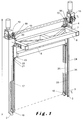
- the figure 1 is a perspective view of the device according to the invention 1 comprising a pair of vertical pylons 2, 3 parallel to each other, each pylon 2, 3 comprising a leading end 4 and a foot end 5.
- the device further comprises a mobile platform 6 arranged to move between the leading end 4 and foot 5 of each pylon, and having an apical face 7 and a basal face 8 opposite to the apical face 7.
- This mobile platform 6 is mounted on each of the towers 2, 3, so that it is placed between them.
- a first plane tangential to the apical face 7 of the mobile platform 6 is oriented perpendicular to an axis A parallel to each pylon 2, 3.
- the lifting device is in particular intended to be placed at the end of platform 9, for example of a waterway such as a river or a river having a water level 10, for loading and unloading boats, and is arranged on the platform 9 so that the first plane tangential to the apical face 7 of the mobile platform 6 is substantially parallel to a second plane passing through a first level 11 corresponding to a lower position of the platform 6 and a third tangent plane passing by a second level 12 corresponding to a high position of the platform 6 and remote from the water level 10 of a first height H1 greater than or equal to 7 meters.
- a waterway such as a river or a river having a water level 10
- the lifting device is in particular intended to be placed at the end of platform 9, for example of a waterway such as a river or a river having a water level 10, for loading and unloading boats, and is arranged on the platform 9 so that the first plane tangential to the apical face 7 of the mobile platform 6 is substantially parallel to a second
- the low position 11 is located at the foot end 5 of each pylon 2, 3 and is distant from the water level by a height of at least 10 centimeters, preferably between 10 and 50 centimeter.
- Each pylon 2, 3 supports, on the one hand, on its leading end 5 a first pulley 13 which is a toothed pulley or a pinion gear, connected by a transmission arm 14 to a motor 15 arranged to rotate the first pulley 13 at a speed of rotation about a first fixed axis of rotation r 1 passing through the transmission arm, the first pulley 13 of the first pylon 2 facing the first pulley 13 of the second pylon 3.
- a first pulley 13 which is a toothed pulley or a pinion gear
- each pylon 2, 3 further supports a second pulley 16 in free rotation around a second fixed axis of rotation r 2 at the foot end 5.
- the second pulley 16 is placed on the pylon 2, 3 so as to be aligned with the first pulley 13 along the axis A parallel to each pylon 2, 3, so that the second pulley 16 of the first pylon 2 faces the second pulley 16 of the second pylon 3.
- the lifting device 1 further comprises a transmission means 17, which is a chain or a toothed belt, arranged to be mounted on the first pulley 13 and the second pulley 16, and to cooperate with them, and which has, on the one hand, a first end 18 connected by means of a first connecting means 19 to a first junction point 20 on the apical face 7 of the mobile platform 6, and on the other hand, a second end 21 connected to the using a second connecting means 22 at a second junction point 23 on the base face 8 of the mobile platform 6, the mobile platform 6, thereby closing said transmission means 16.
- a transmission means 17 which is a chain or a toothed belt, arranged to be mounted on the first pulley 13 and the second pulley 16, and to cooperate with them, and which has, on the one hand, a first end 18 connected by means of a first connecting means 19 to a first junction point 20 on the apical face 7 of the mobile platform 6, and on the other hand, a second end 21 connected to the using a second connecting means 22 at
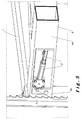
- the second pulley 16 is mounted in a partially closed sealed envelope comprising an opening zone oriented towards the base face 8 of the platform 6 to form an access to the transmission means 17 to the second pulley 16 on which it is mounted.
- the sealed envelope thus makes it possible to protect the gear formed by the transmission means 17 mounted on the second pulley 16 from water and thus to prevent a risk of corrosion of this gear by the rust formation on the latter which can harm to the proper functioning of the device, this risk of corrosion being particularly high when the waterway is seawater.
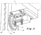
- each pylon 2,3 is preferably a guide rail 24 whose cross section is U-shaped comprising a pair of treads opposite to each other.
- 25, 26 and the platform comprises a pair of freely rotating wheels 27 each wheel of which is arranged to be mounted in the cavity 28 formed by the U-shaped section of each of the rails, as illustrated in FIG. figure 3 .
- A Once mounted in the cavity 28, the tire 29 of each wheel is brought into contact with an inner face of each bearing 25, 26, the inner face facing the tire 29 of the wheel 27, so that when the mobile platform 6 is in motion, the wheel starts to rotate freely along an axis parallel to each tread, thus guiding the movement of the platform along the rail.
- the elevator device further comprises a first control means 30 connected by a first connection means to a regulator 31 of the rotational speed of the first pulley 13 and by a second connection means to a first movable sensor 32 mounted on a towers 2, 3 and free to move along the pylon 2, 3 between the head end 4 and the foot end 5.
- This first sensor 32 is arranged to, on the one hand, determine a first position 33 in the three-dimensional space and, on the other hand, to code this first position 33 into a first signal intended to be sent by the second connection means to the control means 30.
- the preferred type of sensor is a laser position sensor.
- This first position corresponds to a third variable level 33 which can be for example a level of loading or unloading located between the high position 12 and the low position 11 of the mobile platform 6.
- this third variable level 33 may for example correspond at the unloading level of a boat associated for example at the level at which the pontoon of the boat is located or at the upper limit of the hull 34 of a barge.
- the first control means 30 is arranged to process the first signal input, calculate a second reference position 35 distant to a second predetermined threshold height H 2 , for example in a range of values ranging from 0.5 meters to 2 meters, preferably from 0.5 to 1.0 meters, from the position of the third variable level 33 and then code this second reference position into a second signal sent by the first connection means to the regulator 31 arranged to receive this second signal and then translate it for example into a reduction of the speed of rotation of the motor and therefore the speed of movement of the mobile platform 6 when the latter passes through the reference position 35 to approach the position of the third variable level 33.
- This device thus makes it possible to control and systematically adapt the speed of descent of the mobile platform 6 as a function of the level of unloading or loading which continues to descend or rise as the boat is loaded or unloaded.
- the device according to the invention comprises a first security system comprising a first spring 36 arranged to connect the apical face 7 of the mobile platform 6 to the first end 18 of the transmission means 17, this first spring being associated with a second sensor 37 of elongation of the spring.
- the security system comprises a second control means 38 connected to the elongation sensor 37 by a third connection means and to an emergency stop module 39 by a fourth connection means, said emergency stop module. being arranged to stop the rotation of said first pulley 13 and thus the movement of the platform 6, this control means 38 being further arranged to process a third signal sent by said elongation sensor 37 by the third connecting means and corresponding at an elongation value measured by the elongation sensor 37, for comparing this third signal with a second reference signal corresponding to a threshold elongation value and for sending a fourth signal by the fourth connection means to the modulus d emergency stop arranged to translate this fourth signal into a stop of the rotation of the first pulley 13 and therefore the movement of the platform 6 when the elongation value is greater than the threshold elongation value.
- the security system comprises a second spring 40 arranged to connect the basal face 8 of the mobile platform 6 to the second end 21 of the transmission means 17, this second spring being associated with a third sensor 41 of elongation of the spring 40 connected to said second control means 38 by a fifth connection means.
- the device is provided with a second security system consisting in that the basal face 8 of the mobile platform 6 is provided with a fourth contact sensor 42 which is a malleable rod connected by a sixth connection means to the second control means 38.
- the sensor During the descent, if the apical face 7 of the platform 6 approaches for example the upper limit of the hull to a distance such that the malleable rod contacts the shell and is deformed, the sensor The contact card records a deformation which it transforms into a fifth signal sent to the second control means which processes this signal and controls the stopping of the device via the emergency stop module.
- each pylon 2, 3 comprises a series of notches 43 aligned along an edge of a tread of the rail, these notches being included in a fourth plane perpendicular to the first tangential plane of the apical face 7 of the platform mobile 6.
- the platform 6 further has two lateral faces 44, 45 opposite to each other and arranged to connect the apical face 7 to the basal face 8 of the mobile platform 6, each of the lateral faces having a fifth tangent plane parallel to the fourth plane in which the notches 43 are aligned.
- Each of the lateral faces is further provided with a stopper-chute 46 arranged to fit into the notches, said stopper-chute 46 being connected to a pneumatic cylinder 47 or magnetic arranged to engage said stoppe-chute 46 in one of the notches , the cylinder 47 being connected to the second control means 38 arranged to control the cylinder 47 when the rotation of the pulley 13 is stopped.
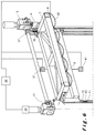
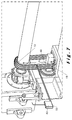
- the device is characterized in that, when the platform 6 empty is in the high position, the first end 18 of said transmission means 17 is at a height H3 of the first pulley 13, this height H3 defines a portion of the transmission means 48 to which is connected a traction / compression sensor 49 integrally connected to a motor support and arranged to be connected to an actuator 50 connected by one of its ends to the part of the transmission means 48.
- the actuator is positioned at a fourth initial level.
- the load by gravity, exerts a force of tension on the transmission means 48 which is stretched from below. This results in an elongation from the bottom of the portion of the transmission means 48 and the first end 18 of the transmission means is spaced from the first pulley 13 of a height H4 greater than the height H3.
- the elongation corresponds to a ⁇ value H which is the difference between the height H3 and H4 height.
- the compression tension sensor converts this ⁇ H elongation value in a measurement of the weight of the load on the feed platform. In this way, the sensor makes it possible to measure the weight of the load both during the loading and during the unloading thereof on the mobile platform 6.
- the motor 15 rotates in a clockwise direction, by means of the rotating arm, the first pulley 13 which pulls down on the means of rotation.
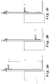
- transmission 17 and a voltage oriented towards the second pulley 16 is generated from the second end of the transmission means 17 connected to the base face 8 of the platform 6 which is empty. This tension initiates the descent of the mobile platform 6 empty along each pylon 2, 3 in a direction from the high position 12 to the low position 11 ( figure 2a ).
- the platform 6 is then slowed down by the control system, controlled by the first control means, as it approaches the third variable level 33 ( figure 2b ) unloading the boat to be loaded.
- the first position is chosen at a predetermined distance preferably between 0.25 and 0.50 meters above the third variable level so that when the boat is unloaded, the pontoon of the boat does not come into contact with the apical face of the platform when raising the level of the pontoon after unloading the goods from the bateu to the platform.
- the platform 6 once loaded is then reassembled.
- the motor 15 rotates counterclockwise, via the rotating arm, the first pulley 13 which then exerts an upward pull on the transmission means 17 and a tension directed towards the first pulley 13 is generated from the first end of the transmission means 17 connected to the apical face 7 of the platform 6.
- This tension initiates the rise of the platform 6 loaded along each pylon 2, 3 in a direction from low position 11 to high position 12.
- the mobile platform 6 is for example stopped at an intermediate position of the third variable level 33 ( Figure 2c ) corresponding to the level of a platform loading platform from which the mobile platform 6 is discharged.
- the engine rotates in a clockwise direction, via the rotating arm, the first pulley 13 which pulls down on the transmission means 17 and a tension directed towards the second pulley 16 is generated from the second end of the transmission means connected to the base face 8 of the platform 6 loaded with the goods.
- This tension initiates the descent of the mobile platform 6 empty along each pylon 2, 3 in a direction from the high position 12 to the low position 11 ( figure 2a ).
- the platform 6 is then slowed down by the control system, controlled by the first control means, as it approaches the third variable level 33 ( figure 2b ) loading the boat to be unloaded.
- the platform 6 once unloaded is then reassembled.
- the motor 15 rotates counterclockwise, via the rotating arm, the first pulley 13 which then exerts an upward pull on the transmission means 17 and a tension directed towards the first pulley 13 is generated from the first end of the transmission means 17 connected to the apical face 7 of the platform 6.
- This tension initiates the rise of the platform 6 discharged along each pylon 2, 3 in a direction from low position 11 to high position 12.
- the mobile platform 6 is for example stopped at an intermediate position of the third variable level 33 ( Figure 2c ) corresponding to the level of an unloading platform of the platform from which the mobile platform is loaded.
Landscapes
- Engineering & Computer Science (AREA)
- Structural Engineering (AREA)
- Mechanical Engineering (AREA)
- Life Sciences & Earth Sciences (AREA)
- Geology (AREA)
- Transportation (AREA)
- Civil Engineering (AREA)
- Ocean & Marine Engineering (AREA)
- Refuge Islands, Traffic Blockers, Or Guard Fence (AREA)
- Advancing Webs (AREA)
- Electrical Discharge Machining, Electrochemical Machining, And Combined Machining (AREA)
- Noodles (AREA)
- Forklifts And Lifting Vehicles (AREA)
Priority Applications (2)
| Application Number | Priority Date | Filing Date | Title |
|---|---|---|---|
| RS20160384A RS54930B1 (sr) | 2013-09-06 | 2014-09-04 | Uređaj za dizanje |
| HRP20160570TT HRP20160570T1 (hr) | 2013-09-06 | 2016-05-27 | Uređaj za podizanje |
Applications Claiming Priority (1)
| Application Number | Priority Date | Filing Date | Title |
|---|---|---|---|
| BE2013/0585A BE1022016B1 (fr) | 2013-09-06 | 2013-09-06 | Dispositif elevateur |
Publications (2)
| Publication Number | Publication Date |
|---|---|
| EP2845835A1 EP2845835A1 (fr) | 2015-03-11 |
| EP2845835B1 true EP2845835B1 (fr) | 2016-03-02 |
Family
ID=49385062
Family Applications (1)
| Application Number | Title | Priority Date | Filing Date |
|---|---|---|---|
| EP14183611.4A Not-in-force EP2845835B1 (fr) | 2013-09-06 | 2014-09-04 | Dispositif élévateur |
Country Status (6)
| Country | Link |
|---|---|
| EP (1) | EP2845835B1 (pl) |
| BE (1) | BE1022016B1 (pl) |
| HR (1) | HRP20160570T1 (pl) |
| HU (1) | HUE028885T2 (pl) |
| PL (1) | PL2845835T3 (pl) |
| RS (1) | RS54930B1 (pl) |
Families Citing this family (5)
| Publication number | Priority date | Publication date | Assignee | Title |
|---|---|---|---|---|
| WO2017165163A1 (en) * | 2016-03-25 | 2017-09-28 | Combs Jerry | Improvements to hand truck and kit thereof |
| DE202017102510U1 (de) * | 2017-04-27 | 2017-06-19 | Hager Sondermaschinenbau Gmbh | Vertikales Achssystem |
| CN109484979A (zh) * | 2017-09-12 | 2019-03-19 | 中国三冶集团有限公司 | 一种建筑工程施工设备及施工方法 |
| CN108975199A (zh) * | 2018-08-22 | 2018-12-11 | 东莞理工学院 | 一种快速运行并高精度定位的自动升降平台及升降机 |
| CN111252708B (zh) * | 2020-03-16 | 2024-10-01 | 诺力智能装备股份有限公司 | 一种适用于agv的机械防撞装置和一种agv |
Family Cites Families (11)
| Publication number | Priority date | Publication date | Assignee | Title |
|---|---|---|---|---|
| JPS60170397U (ja) * | 1984-04-21 | 1985-11-12 | 株式会社 山本製作所 | 簡易型フオ−クリフト |
| DE3738390A1 (de) * | 1987-11-12 | 1989-06-01 | Duerr Gmbh & Co | Hubvorrichtung fuer konsolheber |
| JPH01176798A (ja) * | 1987-12-29 | 1989-07-13 | Sanko Metal Ind Co Ltd | 被昇降物の昇降装置 |
| JPH0639283B2 (ja) * | 1988-11-28 | 1994-05-25 | 小松フォークリフト株式会社 | 棚積機械における過負荷検出装置 |
| JPH0635297U (ja) * | 1992-10-19 | 1994-05-10 | 株式会社タイショー | 穀類収納袋の昇降作業台 |
| JP2536816B2 (ja) * | 1994-02-25 | 1996-09-25 | 光洋自動機株式会社 | 昇降装置 |
| US5971108A (en) * | 1998-01-26 | 1999-10-26 | Yu; Kuo-Liang | Safety device for vertically moving load carrier |
| JP2002047821A (ja) * | 2000-08-07 | 2002-02-15 | Mitsui Miike Mach Co Ltd | 昇降床昇降装置におけるシャッター機構 |
| JP4707166B2 (ja) * | 2001-09-28 | 2011-06-22 | スターテクノ株式会社 | コンテナ昇降装置 |
| JP3761157B2 (ja) * | 2001-10-15 | 2006-03-29 | 株式会社椿本チエイン | 段差解消機 |
| DE102012101949A1 (de) * | 2012-03-08 | 2013-09-12 | Linde Material Handling Gmbh | Hubvorrichtung eines Flurförderzeugs |
-
2013
- 2013-09-06 BE BE2013/0585A patent/BE1022016B1/fr not_active IP Right Cessation
-
2014
- 2014-09-04 EP EP14183611.4A patent/EP2845835B1/fr not_active Not-in-force
- 2014-09-04 HU HUE14183611A patent/HUE028885T2/en unknown
- 2014-09-04 PL PL14183611.4T patent/PL2845835T3/pl unknown
- 2014-09-04 RS RS20160384A patent/RS54930B1/sr unknown
-
2016
- 2016-05-27 HR HRP20160570TT patent/HRP20160570T1/hr unknown
Also Published As
| Publication number | Publication date |
|---|---|
| HRP20160570T1 (hr) | 2016-09-23 |
| PL2845835T3 (pl) | 2016-11-30 |
| BE1022016B1 (fr) | 2016-02-04 |
| EP2845835A1 (fr) | 2015-03-11 |
| RS54930B1 (sr) | 2016-10-31 |
| HUE028885T2 (en) | 2017-01-30 |
Similar Documents
| Publication | Publication Date | Title |
|---|---|---|
| EP2845835A1 (fr) | Dispositif élévateur | |
| EP0384850B1 (fr) | Dispositif automatique d'immobilisation d'un véhicule sur une aire notamment d'un camion devant un quai de chargement | |
| FR2604166A1 (fr) | Dispositif de chargement d'avions | |
| FR2957068A1 (fr) | Dispositif de calage a quai d'un vehicule de transport de marchandises et installation le comportant | |
| EP0061959A1 (fr) | Remorque à plateau mobile et pivotant pour le transport de véhicules divers | |
| CA1074818A (fr) | Procede de transbordement de charges en mer et moyen de mise en oeuvre | |
| EP2781424A1 (fr) | Voiture de véhicule ferroviaire comprenant un système d'accès | |
| WO2006120363A1 (fr) | Dispositif d'élinguage d'une pièce avec compensation d'effort et système de levage le comprenant | |
| EP3209546B1 (fr) | Système de mise a l'eau et de récuperation d'engin marin et sous-marin assisté par des protections inclinables | |
| FR2890951A1 (fr) | Dispositif bloqueur de roue de vehicule | |
| WO2010029181A1 (fr) | Dispositif de calage a quai d'un vehicule de transport en vue de son chargement et dechargement et installation le comportant | |
| KR100761037B1 (ko) | 적재중량에 따라서 제동력이 조절되는 레일 트랜스포터 | |
| CA3196997A1 (fr) | Dispositif et systeme de largage, de maintien en vol et de recuperation d'un aerostat captif | |
| WO2013072596A1 (fr) | Véhicule de remontée mécanique | |
| EP0423029B1 (fr) | Dispositif pour soulever et déplacer des objets et procédé pour sa mise en oeuvre | |
| FR2527155A1 (fr) | Appareil pour la manutention de charges | |
| FR2546836A1 (fr) | Station de telepherique | |
| EP3945005B1 (fr) | Dispositif de protection pour véhicule terrestre | |
| EP3848267A1 (fr) | Véhicule amorti pour le transport de passagers sur une voie de pente variable et installation comprenant ledit véhicule | |
| EP0516511B1 (fr) | Dispositif de remorquage et de manutention d'équipements sous-marins en forme d'aile | |
| FR3087735A1 (fr) | Vehicule ferroviaire pour le transport d’une semi-remorque et procede de chargement d’un tel vehicule ferroviaire | |
| FR2939398A1 (fr) | Dispositif pour securiser la manutention d'une charge roulante sur une plate-forme telle que le pont d'un navire soumis a une mer agitee. | |
| FR3152149A1 (fr) | Méthode d’alerte pour une nacelle élévatrice, notamment une nacelle articulée, et nacelle élévatrice associée | |
| EP0515248B1 (fr) | Dispositif de remorquage et de manutention d'équipements sous-marins | |
| FR3151587A1 (fr) | Système de levage d’un colis, en particulier pour le levage d’un colis en présence d’un mouvement relatif dû à la houle |
Legal Events
| Date | Code | Title | Description |
|---|---|---|---|
| 17P | Request for examination filed |
Effective date: 20140904 |
|
| AK | Designated contracting states |
Kind code of ref document: A1 Designated state(s): AL AT BE BG CH CY CZ DE DK EE ES FI FR GB GR HR HU IE IS IT LI LT LU LV MC MK MT NL NO PL PT RO RS SE SI SK SM TR |
|
| AX | Request for extension of the european patent |
Extension state: BA ME |
|
| PUAI | Public reference made under article 153(3) epc to a published international application that has entered the european phase |
Free format text: ORIGINAL CODE: 0009012 |
|
| GRAP | Despatch of communication of intention to grant a patent |
Free format text: ORIGINAL CODE: EPIDOSNIGR1 |
|
| R17P | Request for examination filed (corrected) |
Effective date: 20150818 |
|
| RBV | Designated contracting states (corrected) |
Designated state(s): AL AT BE BG CH CY CZ DE DK EE ES FI FR GB GR HR HU IE IS IT LI LT LU LV MC MK MT NL NO PL PT RO RS SE SI SK SM TR |
|
| INTG | Intention to grant announced |
Effective date: 20150923 |
|
| GRAS | Grant fee paid |
Free format text: ORIGINAL CODE: EPIDOSNIGR3 |
|
| GRAA | (expected) grant |
Free format text: ORIGINAL CODE: 0009210 |
|
| AK | Designated contracting states |
Kind code of ref document: B1 Designated state(s): AL AT BE BG CH CY CZ DE DK EE ES FI FR GB GR HR HU IE IS IT LI LT LU LV MC MK MT NL NO PL PT RO RS SE SI SK SM TR |
|
| REG | Reference to a national code |
Ref country code: GB Ref legal event code: FG4D Free format text: NOT ENGLISH |
|
| REG | Reference to a national code |
Ref country code: AT Ref legal event code: REF Ref document number: 777884 Country of ref document: AT Kind code of ref document: T Effective date: 20160315 Ref country code: CH Ref legal event code: EP |
|
| REG | Reference to a national code |
Ref country code: IE Ref legal event code: FG4D Free format text: LANGUAGE OF EP DOCUMENT: FRENCH |
|
| REG | Reference to a national code |
Ref country code: DE Ref legal event code: R096 Ref document number: 602014001006 Country of ref document: DE |
|
| REG | Reference to a national code |
Ref country code: HR Ref legal event code: TUEP Ref document number: P20160570 Country of ref document: HR |
|
| REG | Reference to a national code |
Ref country code: RO Ref legal event code: EPE |
|
| REG | Reference to a national code |
Ref country code: NL Ref legal event code: FP |
|
| REG | Reference to a national code |
Ref country code: LT Ref legal event code: MG4D |
|
| PG25 | Lapsed in a contracting state [announced via postgrant information from national office to epo] |
Ref country code: ES Free format text: LAPSE BECAUSE OF FAILURE TO SUBMIT A TRANSLATION OF THE DESCRIPTION OR TO PAY THE FEE WITHIN THE PRESCRIBED TIME-LIMIT Effective date: 20160302 Ref country code: FI Free format text: LAPSE BECAUSE OF FAILURE TO SUBMIT A TRANSLATION OF THE DESCRIPTION OR TO PAY THE FEE WITHIN THE PRESCRIBED TIME-LIMIT Effective date: 20160302 Ref country code: GR Free format text: LAPSE BECAUSE OF FAILURE TO SUBMIT A TRANSLATION OF THE DESCRIPTION OR TO PAY THE FEE WITHIN THE PRESCRIBED TIME-LIMIT Effective date: 20160603 Ref country code: NO Free format text: LAPSE BECAUSE OF FAILURE TO SUBMIT A TRANSLATION OF THE DESCRIPTION OR TO PAY THE FEE WITHIN THE PRESCRIBED TIME-LIMIT Effective date: 20160602 |
|
| PG25 | Lapsed in a contracting state [announced via postgrant information from national office to epo] |
Ref country code: LV Free format text: LAPSE BECAUSE OF FAILURE TO SUBMIT A TRANSLATION OF THE DESCRIPTION OR TO PAY THE FEE WITHIN THE PRESCRIBED TIME-LIMIT Effective date: 20160302 Ref country code: SE Free format text: LAPSE BECAUSE OF FAILURE TO SUBMIT A TRANSLATION OF THE DESCRIPTION OR TO PAY THE FEE WITHIN THE PRESCRIBED TIME-LIMIT Effective date: 20160302 Ref country code: LT Free format text: LAPSE BECAUSE OF FAILURE TO SUBMIT A TRANSLATION OF THE DESCRIPTION OR TO PAY THE FEE WITHIN THE PRESCRIBED TIME-LIMIT Effective date: 20160302 |
|
| REG | Reference to a national code |
Ref country code: FR Ref legal event code: PLFP Year of fee payment: 3 |
|
| REG | Reference to a national code |
Ref country code: HR Ref legal event code: T1PR Ref document number: P20160570 Country of ref document: HR |
|
| PG25 | Lapsed in a contracting state [announced via postgrant information from national office to epo] |
Ref country code: IS Free format text: LAPSE BECAUSE OF FAILURE TO SUBMIT A TRANSLATION OF THE DESCRIPTION OR TO PAY THE FEE WITHIN THE PRESCRIBED TIME-LIMIT Effective date: 20160702 Ref country code: EE Free format text: LAPSE BECAUSE OF FAILURE TO SUBMIT A TRANSLATION OF THE DESCRIPTION OR TO PAY THE FEE WITHIN THE PRESCRIBED TIME-LIMIT Effective date: 20160302 |
|
| PG25 | Lapsed in a contracting state [announced via postgrant information from national office to epo] |
Ref country code: CZ Free format text: LAPSE BECAUSE OF FAILURE TO SUBMIT A TRANSLATION OF THE DESCRIPTION OR TO PAY THE FEE WITHIN THE PRESCRIBED TIME-LIMIT Effective date: 20160302 Ref country code: SM Free format text: LAPSE BECAUSE OF FAILURE TO SUBMIT A TRANSLATION OF THE DESCRIPTION OR TO PAY THE FEE WITHIN THE PRESCRIBED TIME-LIMIT Effective date: 20160302 Ref country code: PT Free format text: LAPSE BECAUSE OF FAILURE TO SUBMIT A TRANSLATION OF THE DESCRIPTION OR TO PAY THE FEE WITHIN THE PRESCRIBED TIME-LIMIT Effective date: 20160704 |
|
| REG | Reference to a national code |
Ref country code: SK Ref legal event code: T3 Ref document number: E 21447 Country of ref document: SK |
|
| REG | Reference to a national code |
Ref country code: DE Ref legal event code: R097 Ref document number: 602014001006 Country of ref document: DE |
|
| PG25 | Lapsed in a contracting state [announced via postgrant information from national office to epo] |
Ref country code: IT Free format text: LAPSE BECAUSE OF FAILURE TO SUBMIT A TRANSLATION OF THE DESCRIPTION OR TO PAY THE FEE WITHIN THE PRESCRIBED TIME-LIMIT Effective date: 20160302 |
|
| PLBE | No opposition filed within time limit |
Free format text: ORIGINAL CODE: 0009261 |
|
| STAA | Information on the status of an ep patent application or granted ep patent |
Free format text: STATUS: NO OPPOSITION FILED WITHIN TIME LIMIT |
|
| REG | Reference to a national code |
Ref country code: HU Ref legal event code: AG4A Ref document number: E028885 Country of ref document: HU |
|
| PG25 | Lapsed in a contracting state [announced via postgrant information from national office to epo] |
Ref country code: DK Free format text: LAPSE BECAUSE OF FAILURE TO SUBMIT A TRANSLATION OF THE DESCRIPTION OR TO PAY THE FEE WITHIN THE PRESCRIBED TIME-LIMIT Effective date: 20160302 |
|
| 26N | No opposition filed |
Effective date: 20161205 |
|
| PG25 | Lapsed in a contracting state [announced via postgrant information from national office to epo] |
Ref country code: SI Free format text: LAPSE BECAUSE OF FAILURE TO SUBMIT A TRANSLATION OF THE DESCRIPTION OR TO PAY THE FEE WITHIN THE PRESCRIBED TIME-LIMIT Effective date: 20160302 |
|
| PG25 | Lapsed in a contracting state [announced via postgrant information from national office to epo] |
Ref country code: MC Free format text: LAPSE BECAUSE OF FAILURE TO SUBMIT A TRANSLATION OF THE DESCRIPTION OR TO PAY THE FEE WITHIN THE PRESCRIBED TIME-LIMIT Effective date: 20160302 |
|
| REG | Reference to a national code |
Ref country code: IE Ref legal event code: MM4A |
|
| PG25 | Lapsed in a contracting state [announced via postgrant information from national office to epo] |
Ref country code: IE Free format text: LAPSE BECAUSE OF NON-PAYMENT OF DUE FEES Effective date: 20160904 |
|
| REG | Reference to a national code |
Ref country code: FR Ref legal event code: PLFP Year of fee payment: 4 |
|
| PG25 | Lapsed in a contracting state [announced via postgrant information from national office to epo] |
Ref country code: LU Free format text: LAPSE BECAUSE OF NON-PAYMENT OF DUE FEES Effective date: 20160904 |
|
| REG | Reference to a national code |
Ref country code: AT Ref legal event code: UEP Ref document number: 777884 Country of ref document: AT Kind code of ref document: T Effective date: 20160302 |
|
| PG25 | Lapsed in a contracting state [announced via postgrant information from national office to epo] |
Ref country code: MK Free format text: LAPSE BECAUSE OF FAILURE TO SUBMIT A TRANSLATION OF THE DESCRIPTION OR TO PAY THE FEE WITHIN THE PRESCRIBED TIME-LIMIT Effective date: 20160302 Ref country code: MT Free format text: LAPSE BECAUSE OF FAILURE TO SUBMIT A TRANSLATION OF THE DESCRIPTION OR TO PAY THE FEE WITHIN THE PRESCRIBED TIME-LIMIT Effective date: 20160302 Ref country code: CY Free format text: LAPSE BECAUSE OF FAILURE TO SUBMIT A TRANSLATION OF THE DESCRIPTION OR TO PAY THE FEE WITHIN THE PRESCRIBED TIME-LIMIT Effective date: 20160302 |
|
| REG | Reference to a national code |
Ref country code: HR Ref legal event code: ODRP Ref document number: P20160570 Country of ref document: HR Payment date: 20180903 Year of fee payment: 5 |
|
| REG | Reference to a national code |
Ref country code: FR Ref legal event code: PLFP Year of fee payment: 5 |
|
| PG25 | Lapsed in a contracting state [announced via postgrant information from national office to epo] |
Ref country code: TR Free format text: LAPSE BECAUSE OF FAILURE TO SUBMIT A TRANSLATION OF THE DESCRIPTION OR TO PAY THE FEE WITHIN THE PRESCRIBED TIME-LIMIT Effective date: 20160302 Ref country code: AL Free format text: LAPSE BECAUSE OF FAILURE TO SUBMIT A TRANSLATION OF THE DESCRIPTION OR TO PAY THE FEE WITHIN THE PRESCRIBED TIME-LIMIT Effective date: 20160302 |
|
| PGFP | Annual fee paid to national office [announced via postgrant information from national office to epo] |
Ref country code: SK Payment date: 20180702 Year of fee payment: 13 Ref country code: BG Payment date: 20180927 Year of fee payment: 5 Ref country code: PL Payment date: 20180903 Year of fee payment: 5 Ref country code: HR Payment date: 20180903 Year of fee payment: 5 Ref country code: HU Payment date: 20180914 Year of fee payment: 5 |
|
| GBPC | Gb: european patent ceased through non-payment of renewal fee |
Effective date: 20180904 |
|
| PG25 | Lapsed in a contracting state [announced via postgrant information from national office to epo] |
Ref country code: GB Free format text: LAPSE BECAUSE OF NON-PAYMENT OF DUE FEES Effective date: 20180904 |
|
| PGFP | Annual fee paid to national office [announced via postgrant information from national office to epo] |
Ref country code: AT Payment date: 20190919 Year of fee payment: 6 |
|
| REG | Reference to a national code |
Ref country code: HR Ref legal event code: PBON Ref document number: P20160570 Country of ref document: HR Effective date: 20190904 |
|
| PG25 | Lapsed in a contracting state [announced via postgrant information from national office to epo] |
Ref country code: RO Free format text: LAPSE BECAUSE OF NON-PAYMENT OF DUE FEES Effective date: 20190904 |
|
| PG25 | Lapsed in a contracting state [announced via postgrant information from national office to epo] |
Ref country code: RS Free format text: LAPSE BECAUSE OF NON-PAYMENT OF DUE FEES Effective date: 20200309 |
|
| REG | Reference to a national code |
Ref country code: CH Ref legal event code: PL |
|
| REG | Reference to a national code |
Ref country code: SK Ref legal event code: MM4A Ref document number: E 21447 Country of ref document: SK Effective date: 20190904 |
|
| PG25 | Lapsed in a contracting state [announced via postgrant information from national office to epo] |
Ref country code: LI Free format text: LAPSE BECAUSE OF NON-PAYMENT OF DUE FEES Effective date: 20190930 Ref country code: CH Free format text: LAPSE BECAUSE OF NON-PAYMENT OF DUE FEES Effective date: 20190930 |
|
| PG25 | Lapsed in a contracting state [announced via postgrant information from national office to epo] |
Ref country code: HR Free format text: LAPSE BECAUSE OF NON-PAYMENT OF DUE FEES Effective date: 20190904 Ref country code: HU Free format text: LAPSE BECAUSE OF NON-PAYMENT OF DUE FEES Effective date: 20190905 Ref country code: BG Free format text: LAPSE BECAUSE OF NON-PAYMENT OF DUE FEES Effective date: 20200531 Ref country code: SK Free format text: LAPSE BECAUSE OF NON-PAYMENT OF DUE FEES Effective date: 20190904 |
|
| PGFP | Annual fee paid to national office [announced via postgrant information from national office to epo] |
Ref country code: NL Payment date: 20200923 Year of fee payment: 7 Ref country code: DE Payment date: 20200928 Year of fee payment: 7 Ref country code: FR Payment date: 20200923 Year of fee payment: 7 |
|
| PGFP | Annual fee paid to national office [announced via postgrant information from national office to epo] |
Ref country code: BE Payment date: 20200923 Year of fee payment: 7 |
|
| REG | Reference to a national code |
Ref country code: AT Ref legal event code: MM01 Ref document number: 777884 Country of ref document: AT Kind code of ref document: T Effective date: 20200904 |
|
| PG25 | Lapsed in a contracting state [announced via postgrant information from national office to epo] |
Ref country code: AT Free format text: LAPSE BECAUSE OF NON-PAYMENT OF DUE FEES Effective date: 20200904 |
|
| REG | Reference to a national code |
Ref country code: DE Ref legal event code: R119 Ref document number: 602014001006 Country of ref document: DE |
|
| REG | Reference to a national code |
Ref country code: NL Ref legal event code: MM Effective date: 20211001 |
|
| REG | Reference to a national code |
Ref country code: BE Ref legal event code: MM Effective date: 20210930 |
|
| PG25 | Lapsed in a contracting state [announced via postgrant information from national office to epo] |
Ref country code: PL Free format text: LAPSE BECAUSE OF NON-PAYMENT OF DUE FEES Effective date: 20190904 |
|
| PG25 | Lapsed in a contracting state [announced via postgrant information from national office to epo] |
Ref country code: NL Free format text: LAPSE BECAUSE OF NON-PAYMENT OF DUE FEES Effective date: 20211001 |
|
| PG25 | Lapsed in a contracting state [announced via postgrant information from national office to epo] |
Ref country code: FR Free format text: LAPSE BECAUSE OF NON-PAYMENT OF DUE FEES Effective date: 20210930 Ref country code: DE Free format text: LAPSE BECAUSE OF NON-PAYMENT OF DUE FEES Effective date: 20220401 Ref country code: BE Free format text: LAPSE BECAUSE OF NON-PAYMENT OF DUE FEES Effective date: 20210930 |