EP2845551A1 - Chirurgisches Instrument mit verbessertem Betätigungsgetriebe - Google Patents
Chirurgisches Instrument mit verbessertem Betätigungsgetriebe Download PDFInfo
- Publication number
- EP2845551A1 EP2845551A1 EP14184274.0A EP14184274A EP2845551A1 EP 2845551 A1 EP2845551 A1 EP 2845551A1 EP 14184274 A EP14184274 A EP 14184274A EP 2845551 A1 EP2845551 A1 EP 2845551A1
- Authority
- EP
- European Patent Office
- Prior art keywords
- movement
- instrument according
- operating lever
- blocking
- carriage
- Prior art date
- Legal status (The legal status is an assumption and is not a legal conclusion. Google has not performed a legal analysis and makes no representation as to the accuracy of the status listed.)
- Granted
Links
- 230000033001 locomotion Effects 0.000 claims abstract description 62
- 230000000903 blocking effect Effects 0.000 claims abstract description 44
- 230000007246 mechanism Effects 0.000 claims abstract description 10
- 230000005540 biological transmission Effects 0.000 abstract description 5
- 238000010276 construction Methods 0.000 abstract description 2
- 230000001419 dependent effect Effects 0.000 description 2
- 238000005096 rolling process Methods 0.000 description 2
- 230000004888 barrier function Effects 0.000 description 1
- 230000008859 change Effects 0.000 description 1
- 230000006835 compression Effects 0.000 description 1
- 238000007906 compression Methods 0.000 description 1
- 238000013461 design Methods 0.000 description 1
- 238000005516 engineering process Methods 0.000 description 1
- 239000004744 fabric Substances 0.000 description 1
- 238000000034 method Methods 0.000 description 1
- 230000004048 modification Effects 0.000 description 1
- 238000012986 modification Methods 0.000 description 1
- 229920003023 plastic Polymers 0.000 description 1
- 239000004033 plastic Substances 0.000 description 1
- 230000008569 process Effects 0.000 description 1
- 230000000717 retained effect Effects 0.000 description 1
- 210000002105 tongue Anatomy 0.000 description 1
- 238000012549 training Methods 0.000 description 1
- 238000013519 translation Methods 0.000 description 1
Images

Classifications
-
- A—HUMAN NECESSITIES
- A61—MEDICAL OR VETERINARY SCIENCE; HYGIENE
- A61B—DIAGNOSIS; SURGERY; IDENTIFICATION
- A61B18/00—Surgical instruments, devices or methods for transferring non-mechanical forms of energy to or from the body
- A61B18/04—Surgical instruments, devices or methods for transferring non-mechanical forms of energy to or from the body by heating
- A61B18/12—Surgical instruments, devices or methods for transferring non-mechanical forms of energy to or from the body by heating by passing a current through the tissue to be heated, e.g. high-frequency current
- A61B18/14—Probes or electrodes therefor
- A61B18/1442—Probes having pivoting end effectors, e.g. forceps
- A61B18/1445—Probes having pivoting end effectors, e.g. forceps at the distal end of a shaft, e.g. forceps or scissors at the end of a rigid rod
-
- A—HUMAN NECESSITIES
- A61—MEDICAL OR VETERINARY SCIENCE; HYGIENE
- A61B—DIAGNOSIS; SURGERY; IDENTIFICATION
- A61B17/00—Surgical instruments, devices or methods
- A61B17/28—Surgical forceps
- A61B17/29—Forceps for use in minimally invasive surgery
- A61B17/295—Forceps for use in minimally invasive surgery combined with cutting implements
-
- A—HUMAN NECESSITIES
- A61—MEDICAL OR VETERINARY SCIENCE; HYGIENE
- A61B—DIAGNOSIS; SURGERY; IDENTIFICATION
- A61B17/00—Surgical instruments, devices or methods
- A61B17/00234—Surgical instruments, devices or methods for minimally invasive surgery
- A61B2017/00353—Surgical instruments, devices or methods for minimally invasive surgery one mechanical instrument performing multiple functions, e.g. cutting and grasping
-
- A—HUMAN NECESSITIES
- A61—MEDICAL OR VETERINARY SCIENCE; HYGIENE
- A61B—DIAGNOSIS; SURGERY; IDENTIFICATION
- A61B17/00—Surgical instruments, devices or methods
- A61B17/28—Surgical forceps
- A61B17/29—Forceps for use in minimally invasive surgery
- A61B17/2909—Handles
- A61B2017/2912—Handles transmission of forces to actuating rod or piston
- A61B2017/2913—Handles transmission of forces to actuating rod or piston cams or guiding means
-
- A—HUMAN NECESSITIES
- A61—MEDICAL OR VETERINARY SCIENCE; HYGIENE
- A61B—DIAGNOSIS; SURGERY; IDENTIFICATION
- A61B17/00—Surgical instruments, devices or methods
- A61B17/28—Surgical forceps
- A61B17/29—Forceps for use in minimally invasive surgery
- A61B17/2909—Handles
- A61B2017/2912—Handles transmission of forces to actuating rod or piston
- A61B2017/2913—Handles transmission of forces to actuating rod or piston cams or guiding means
- A61B2017/2916—Handles transmission of forces to actuating rod or piston cams or guiding means pins in guiding slots
-
- A—HUMAN NECESSITIES
- A61—MEDICAL OR VETERINARY SCIENCE; HYGIENE
- A61B—DIAGNOSIS; SURGERY; IDENTIFICATION
- A61B17/00—Surgical instruments, devices or methods
- A61B17/28—Surgical forceps
- A61B17/29—Forceps for use in minimally invasive surgery
- A61B17/2909—Handles
- A61B2017/2912—Handles transmission of forces to actuating rod or piston
- A61B2017/2923—Toothed members, e.g. rack and pinion
-
- A—HUMAN NECESSITIES
- A61—MEDICAL OR VETERINARY SCIENCE; HYGIENE
- A61B—DIAGNOSIS; SURGERY; IDENTIFICATION
- A61B18/00—Surgical instruments, devices or methods for transferring non-mechanical forms of energy to or from the body
- A61B18/04—Surgical instruments, devices or methods for transferring non-mechanical forms of energy to or from the body by heating
- A61B18/12—Surgical instruments, devices or methods for transferring non-mechanical forms of energy to or from the body by heating by passing a current through the tissue to be heated, e.g. high-frequency current
- A61B18/14—Probes or electrodes therefor
- A61B18/1442—Probes having pivoting end effectors, e.g. forceps
- A61B2018/1452—Probes having pivoting end effectors, e.g. forceps including means for cutting
- A61B2018/1455—Probes having pivoting end effectors, e.g. forceps including means for cutting having a moving blade for cutting tissue grasped by the jaws
Definitions
- the invention relates to an instrument, in particular an electrosurgical instrument, with a tool having members which are to be actuated sequentially.
- distal always describes the part of the instrument or component removed by the user
- proximal always describes the closer part of the instrument or component directed towards the user
- Such electrosurgical instruments are for example from the EP 2 371 316 A1 known.
- the tool is there a mouth with two branches, of which at least one is pivotable.
- the industry is moved by a tension element in the closing direction.
- a knife is slidably mounted. When the branches are closed, the knife is activated by moving it distally. To operate the knife is a sliding element.
- the pulling element and the sliding element are connected to an actuating gear, which is arranged in a housing.
- an operating lever is provided which generates the pulling movement for closing the industry on the first part of its movement path and on the second part of its movement path, the sliding movement for advancing the knife.
- the closing movement in the industry is implemented via a toggle mechanism.
- the surgical instrument according to the invention has a slide mechanism for the successive implementation of the movement of the operating lever in a movement of the tension element and in an opposite movement of the sliding element.
- the generation of the movement takes place by means of a link and thus opens up a wide scope for the ratio of the pivotal movement of the operating lever to the closing movement of the branches of a tool.
- the law of motion is not predetermined by a toggle lever arrangement, but can be chosen largely freely by the choice of the shape of the scenery.
- the closing force acting between the two branches can be precisely determined while ensuring that it is maintained under different operating conditions even with different fabric properties.
- the operating lever also has a blocking gate which blocks movement of the knife as long as the branches are not completely closed. This results in a total of a simple and clear design and a secure function under approval of the usual in plastics technology tolerances.
- the sliding gear on a locking element for controlled blocking a movement of the sliding element.
- the locking element can be on the carriage act, which serves the knife operation. As a result, too early or unintentional operation of the knife can be safely excluded.
- FIG. 1 an instrument 10 is schematically illustrated which comprises a housing 11 with a shaft 12 extending therefrom. On the housing 11, a handle 13 is formed, in the vicinity of an operating lever 14 is arranged.
- a tool 15 is arranged, which has two branches 16, 17. From this at least one pivotally mounted, so that the mouth formed between the branches 16, 17 can be opened and closed.
- FIG. 2 illustrates this process schematically.
- the sectors 16, 17 of the tool 15 are supported by suitable, not further illustrated pivot bearing 18, 19 toward each other and away from each other pivotally.
- pivot bearing 18, 19 toward each other and away from each other pivotally.
- pull elements 20, 21 extend, which extend through the shaft 12 into the housing 11.
- a knife 22 which is slidably supported to retract into a straight or curved knife guide groove defined by the branches 16, 17 and to sever tissue caught between the branches 16, 17.
- the knife 22 cuts, for example, with its transversely oriented to the direction of the front edge. It is moved by a sliding element 23, which preferably extends between the tension elements 20, 21 12 through the shaft into the housing 11 inside.
- the arranged in the housing 11 gear 24 for implementing the movement of the operating lever 14 in a pulling movement of the tension members 20, 21 and a pushing movement of the sliding member 23 is in FIG. 3 separately schematically illustrated.
- the operating lever 14 has a gripping opening 25 at the bottom. At its other end, it is engaged with a gear 26, which is rotatably mounted on the operating lever 14 and displaceable in the longitudinal direction of the lever.
- the operating lever 14 has for receiving the axis of the gear 26, for example, a guide for the gear, for example in the form of a slot or a forked end 27.
- the gear 26 is engaged with a stationary on the housing 11 formed rack 28 into engagement. On its opposite side, the gear 26 is connected to a rack 30 of a carriage 29 in connection. This rack forms a slide toothing 30 which extends parallel to the rack 28.
- the carriage 29 is movable parallel to the rack 28 and serves to actuate the blade 22.
- the rack 28, the gear 26 and the rack 30 of the carriage 29 form a rack and pinion.
- a blocking gate 31 is formed, which has two mutually angled sections 32, 33.
- the blocking gate 31 is penetrated by a pin 34 which is fixedly arranged in the housing 11.
- the blocking gate 31 moves with the operating lever 14 so that upon actuation of the branches 16, 17 the pin 34 is located in the first section 32.
- the pin 34 is located in the second section 33.
- a first arm 38 of the lever 37 is pivotally connected to the operating lever 14. Its second arm 39 in turn carries a link 40, which serves to actuate a carriage 41 for the tension elements 20, 21.
- the curved, almost transverse to the second arm 39 extending backdrop 40 leads a link pin 42 which is connected to the carriage 41.
- the carriage 41 is connected via a spring element 43, such as a compression spring, with the indicated by a dashed line tension members 20, 21.
- a locking device 44 is provided. This includes one or more locking lever 45, which is assigned to a formed on the housing 11 stop 46.
- the locking lever 45 can be disengaged from the stop 46 by manual operation to release the blade movement.
- the locking lever 45 then runs against the stop 46 when the operating lever 14 is actuated, when the pin 34 stands between the two sections 32, 33 of the blocking guide 31.
- the instrument 10 operates with reference to the following FIGS. 4 to 6 as follows:
- the operating lever 14 is prevented by the portion 32 of the blocking gate 31 from pivoting significantly with its upper end in the distal direction. He is therefore at the top in the in FIGS. 4 and 5 right position, that is held up in its proximal position while performing a first pivotal movement. He is about the arm 38 to the center of the slide pin 36 as (first, provisional) pivot or pivot point P1 connected.
- the operating lever 14 By the pivotal movement of the operating lever 14, the operating lever 14 is slightly displaced in the vertical direction (i.e., in its longitudinal direction). As a result, the blocking gate 31 reaches the top until the pin 34 is in the angle of the blocking gate 31, that is, between the sections 32, 33. The locking lever 45 runs against the stop 46 and initially blocks any further movement.
- the entire route includes two functions.
- the carriage 41 is moved and the branches 16, 17 are closed.
- the longitudinal movement of the carriage 41 is dependent on the volume of tissue caught between the branches 16, 17.
- the branches 16, 17 are clamped.
- the lengths of the two sections change. If, for example, no tissue is grasped between the sectors 16, 17, the section in which the branches 16, 17 are clamped comprises only the last region of the guide path of the guide 40. If large-volume tissue is caught between the branches 16, 17, the section of the slide path which applies the clamping force can comprise almost the entire slide path.
- the two-armed lever 37, the link 40 and the link pin 42 form a link mechanism.
- the spring element 43 is biased. This ensures that, after the complete link path has passed through, the tissue gripped between the sectors 16, 17 is held with a predefined minimum clamping force.
- the locking device 44 pivots, for example by a suitable lever transmission mechanism 47, the locking lever 45 away from the stop 46, so that a further movement of the operating lever 14 is released on the handle 13 back.
- the gate 40 is in the end stop and thus prevents further pivoting of the two-armed lever 37.
- the blocking gate 31 is also released. Therefore, now the gear 26 moves on the rack 28 rolling in the distal direction. Due to the double circumferential speed of the gear 26 relative to its linear feed speed, the carriage 29 is conveyed in this direction at twice the speed and correspondingly twice the stroke.
- the sliding member 23 is advanced very quickly in this way.
- the laws of motion can be made relatively free by arrangement and training of the involved two scenes 31 and 40 in wide limits.
- By changing the pivot from P1 to P2 can also be in addition to the otherwise existing differences produce additional translation differences between the actuation of the branches 16, 17 and the knife 22. It is thus possible to generate a movement of the branches 16, 17 in a locally and force-controlled manner and a rapid cutting movement of the knife 22.
- FIGS. 7 to 10 a modified embodiment of the instrument 10 according to the invention is illustrated. Structure and function of this instrument 10 is based on the structure and function of the instrument 10 after the FIGS. 1 to 6 , It is based on the same reference numerals and reference is made to the previous description.
- the modification of the instrument 10 after the FIGS. 7 to 10 is located in a locking device 50 to prevent unwanted operation of the blade 20.
- the locking device 50 has at least one locking element 51 and one or more actuators 52 on.
- the locking element 51 is adapted to lock the carriage 29 in its rest position.
- the blocking element 51 may be displaceable or, as shown in the example, pivotally mounted.
- On the blocking element 51 may be provided in the form of a projection, a nose or the like, formed lock 56 which engages in a corresponding recess of the carriage 29 and thereby prevents its longitudinal movement.
- the pivot point of the locking element 51 is preferably arranged in a straight extension of the carriage 29.
- the actuating element 52 is preferably a manual operating element with which the locking element can be selectively transferred from its blocking position, in which it engages with the carriage 29, into a release position.
- the actuating element 52 can be attached to the side of the housing Rockers, levers, push buttons or knobs or the like may be provided.
- the locking device 50 is preferably foreign lockable. To lock the locking device 50 in the locked position, the position of the carriage 41 can be used, which causes the closing of the tool 15.
- an extension 58 may be provided on the blocking element 51, which extension is designed as a cam follower element 53 at its end.
- the cam follower element 53 is associated with a cam 54 which may be mounted laterally projecting on the carriage 41.
- the cam follower element 53 preferably has an inclined surface facing the cam 54 and a blocking surface which bears against the cam 54 when the carriage 41 is in the starting position (FIG. FIG. 7 ) and the blocking element 51 is in the locked position.
- locking means 51 may be associated with a latching means such that it is movable in either of its two positions, i. its blocking position and its release position, remains until it is transferred by sufficient external forces, overcoming a resistance in its other position.
- a locking means can be formed for example by a detent opening 55 in the detent element and an associated detent projection 57, which is arranged on the inside of the housing 11 and over which the locking element 51 must snap to get from one position to its other.
- Other locking means for example in the form of spring-mounted tongues and associated recesses, spring-loaded balls, snap spring arrangements or the like, can be used.
- the instrument 10 is initially in the initial state after FIG. 7 ,
- the operating lever 14 is in the distal position.
- the two carriages 29, 41 are in rest position.
- the blocking element 51 is in the blocking position, in which the catch 56 engages in a corresponding recess of the carriage 29 and thus locks it.
- the cam follower element 53 lies with its locking surface on the cam 54.
- the locking element 51 is thereby locked in its blocking position. A user may as much as he actuate the actuator 52, no unlocking of the carriage 29 and thus cause no operation of the knife.
- the carriage 29 When moved towards the handle 13, the carriage 29 initially remains in its back-related proximal, ie non-active position.
- the section 32 of the blocking gate 31 initially prevents the operating lever 14 from pivoting significantly with its upper end in the distal direction.
- this first movement of the operating lever 14 leads as in connection with the FIGS. 1 to 6 described that the carriage 41 is moved in the proximal direction.
- the operating lever 14 and thus the blocking gate 31 slides in this first movement phase along the first portion 32 on the pin 34 to the gear 26 back.
- the blocking element 51 initially further prevents movement of the carriage 29.
- the blocking element 51 blocks a distal movement of the carriage 29 via the latching projection 54 also the gear 26 and the upper end of the Operating lever 14 is blocked in their movement.
- the operating lever 14 can not be moved further in the direction of the handle 13.
- FIG. 8 illustrates the instrument 10 at the end of this first movement section, in which the branches of the tool 15 are closed.
- FIG. 9 shows the unlocked locking member 51 of the instrument 10, but before operation of the operating lever fourteenth
- FIG. 10 illustrates the instrument 10 at the end of the second movement section during which the knife has been extended.
- the carriage 41 again moves into its distal rest position.
- the cam 54 runs against the inclined surface of the cam follower element 53 facing it and urges the extension 58 upwards.
- the locking element 51 is thereby transferred, overcoming its tendency to lock in the locked position, in which the lock 56 engages in the recess of the carriage 29.
- the carriage 29 is thus blocked again in the rest position.
- the blocking element 51 can also be returned to its starting position via a spring. For example, it can snap upwards even after the carriage 29 has been moved back.
- the blocking element By means of corresponding contours on the carriage 29 and on the blocking element 51, the blocking element must be held in the release position during the blade movement in this case. Locking positions are dispensable in this case. In such solutions, however, the actuator 52 must be retained at the beginning of the movement of the knife.
- An instrument 10 according to the invention has a slotted link mechanism with a blocking slotted guide 31 and a guide 40 serving for force transmission and control, in order firstly to generate a pulling movement on tension elements 20, 21 and then a sliding movement on a sliding element 23.
- the concept allows a tolerance-insensitive, functionally reliable construction.
Landscapes
- Health & Medical Sciences (AREA)
- Surgery (AREA)
- Life Sciences & Earth Sciences (AREA)
- Engineering & Computer Science (AREA)
- Biomedical Technology (AREA)
- Public Health (AREA)
- Nuclear Medicine, Radiotherapy & Molecular Imaging (AREA)
- Veterinary Medicine (AREA)
- General Health & Medical Sciences (AREA)
- Heart & Thoracic Surgery (AREA)
- Medical Informatics (AREA)
- Molecular Biology (AREA)
- Animal Behavior & Ethology (AREA)
- Physics & Mathematics (AREA)
- Otolaryngology (AREA)
- Plasma & Fusion (AREA)
- Ophthalmology & Optometry (AREA)
- Surgical Instruments (AREA)
Abstract
Description
- Die Erfindung betrifft ein Instrument, insbesondere ein elektrochirurgisches Instrument, mit einem Werkzeug, das Glieder aufweist, die nacheinander zu betätigen sind.
- Im Folgenden beschreibt der Begriff "distal" stets den vom Anwender entfernten Teil des Instruments oder Bauteils, der Begriff "proximal" beschreibt stets den zum Anwender hin gerichteten näher liegenden Teil des Instruments oder Bauteils.
- Solche elektrochirurgischen Instrumente sind beispielsweise aus der
EP 2 371 316 A1 bekannt. Das Werkzeug ist dort ein Maul mit zwei Branchen, von denen wenigstens eine schwenkbeweglich ist. Die Branche wird durch ein Zugelement in Schließrichtung bewegt. Zwischen den Branchen ist ein Messer verschiebbar gelagert. Sind die Branchen geschlossen, wird das Messer aktiviert, indem es in distaler Richtung verschoben wird. Zur Betätigung des Messers dient ein Schiebeelement. - Das Zugelement und das Schiebeelement sind mit einem Betätigungsgetriebe verbunden, das in einem Gehäuse angeordnet ist. Als Antrieb ist ein Bedienhebel vorgesehen, der auf dem ersten Teil seines Bewegungswegs die Zugbewegung zum Schließen der Branche und auf dem zweiten Teil seines Bewegungswegs die Schiebebewegung zum Vorschieben des Messers erzeugt. Die Schließbewegung in der Branche wird dabei über ein Kniehebelgetriebe umgesetzt.
- Es besteht der Wunsch nach verbesserter Kontrolle der Schließbewegung und der auf das Gewebe einwirkenden Kraft.
- Diese Aufgabe wird mit dem chirurgischen Instrument nach Anspruch 1 erzielt.
- Das erfindungsgemäße chirurgische Instrument weist ein Kulissengetriebe zur aufeinanderfolgenden Umsetzung der Bewegung des Bedienhebels in eine Bewegung des Zugelements und in eine entgegengesetzte Bewegung des Schiebeelements auf. Die Erzeugung der Bewegung erfolgt mittels einer Kulisse und eröffnet damit einen weiten Gestaltungsspielraum hinsichtlich des Verhältnisses der Schwenkbewegung des Bedienhebels zur Schließbewegung der Branchen eines Werkzeugs. Das Bewegungsgesetz ist nicht durch eine Kniehebelanordnung vorgegeben, sondern kann durch die Wahl der Form der Kulisse weitgehend frei gewählt werden. In Verbindung mit einer Federanordnung zwischen dem Getriebe und dem einen oder mehreren Zugelementen zur Betätigung einer oder beiden Branchen kann die zwischen beiden Branchen wirkende Schließkraft genau festgelegt und dabei sichergestellt werden, dass sie unter verschiedenen Betriebsbedingungen auch mit unterschiedlichen Gewebeeigenschaften eingehalten wird.
- Der Betätigungshebel weist außerdem eine Sperrkulisse auf, die eine Bewegung des Messers so lange sperrt, wie die Branchen nicht vollständig geschlossen sind. Dies ergibt insgesamt einen einfachen und übersichtlichen Aufbau und eine sichere Funktion unter Zulassung der in der Kunststofftechnik üblichen Toleranzen.
- Vorzugsweise weist das Kulissengetriebe ein Sperrelement zur gesteuerten Blockierung einer Bewegung des Schiebeelements auf. Das Sperrelement kann auf den Schlitten wirken, der der Messerbetätigung dient. Dadurch kann eine zu frühe oder unbeabsichtigte Betätigung des Messers sicher ausgeschlossen werden.
- Einzelheiten vorteilhafter Ausführungsformen der Erfindung ergeben sich aus Unteransprüchen, der Beschreibung und/oder der Zeichnung. Es zeigen:
-
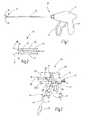
Figur 1 das erfindungsgemäße Instrument in einer Gesamtansicht in Prinzipdarstellung, -
Figur 2 das Werkzeug des Instruments nachFigur 1 , in schematisierter Prinzipdarstellung, -
Figur 3 das Getriebe des Instruments nachFigur 1 , in schematisierter Prinzipdarstellung, -
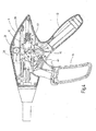
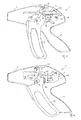
Figur 4 das Instrument nachFigur 1 mit geöffnetem Gehäuse, in Ausgangsposition, -
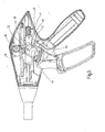
Figur 5 das Instrument nachFigur 4 in der Betätigungsposition für das geschlossene Werkzeug vor Betätigung des Messers, -
Figur 6 das Instrument nachFigur 4 und5 bei betätigtem Messer -
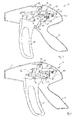
Figur 7 ein Instrument in abgewandelter Ausführungsform mit geöffnetem Gehäuse, in Ausgangsposition, -
Figur 8 das Instrument nachFigur 7 in Betätigungsposition bei geschlossenem Werkzeug und verriegeltem Messer, -
Figur 9 das Instrument nachFigur 7 in Betätigungsposition bei geschlossenem Werkzeug und entriegeltem Messer und -
Figur 10 das Instrument nachFigur 7 in Betätigungsposition bei geschlossenem Werkzeug und betätigtem Messer. - In
Figur 1 ist ein Instrument 10 schematisch veranschaulicht, das ein Gehäuse 11 mit einem sich von diesem wegerstreckenden Schaft 12 aufweist. An dem Gehäuse 11 ist ein Handgriff 13 ausgebildet, in dessen Nachbarschaft ein Bedienhebel 14 angeordnet ist. - An dem distalen Ende des Schafts 12 ist ein Werkzeug 15 angeordnet, das zwei Branchen 16, 17 aufweist. Von diesem ist mindestens eine schwenkbeweglich gelagert, so dass das zwischen den Branchen 16, 17 gebildete Maul geöffnet und geschlossen werden kann.
-
Figur 2 veranschaulicht diesen Vorgang schematisch. Die Branchen 16, 17 des Werkzeugs 15 sind durch geeignete, nicht weiter veranschaulichte Schwenklager 18, 19 aufeinander zu und voneinander weg schwenkbeweglich gelagert. Zur Betätigung setzen an den proximalen Enden der Branchen 16, 17 Zugelemente 20, 21 an, die sich durch den Schaft 12 hindurch bis in das Gehäuse 11 hinein erstrecken. - Zu dem Werkzeug 15 gehört außerdem ein Messer 22 das schiebebeweglich gelagert ist, um in eine von den Branchen 16, 17 festgelegte gerade oder gekrümmte Messerführungsnut einzufahren und zwischen den Branchen 16, 17 gefasstes Gewebe zu durchtrennen. Das Messer 22 schneidet dabei zum Beispiel mit seiner quer zur Bewegungsrichtung orientierten Stirnkante. Es wird durch ein Schiebeelement 23 bewegt, das sich vorzugsweise zwischen den Zugelementen 20, 21 12 durch den Schaft bis in das Gehäuse 11 hinein erstreckt.
- Das in dem Gehäuse 11 angeordnete Getriebe 24 zur Umsetzung der Bewegung des Bedienhebels 14 in eine Zugbewegung der Zugelemente 20, 21 und eine Schubbewegung des Schiebeelements 23 ist in
Figur 3 gesondert schematisch veranschaulicht. Der Bedienhebel 14 weist unten eine Greiföffnung 25 auf. An seinem anderen Ende steht er mit einem Zahnrad 26 in Eingriff, das an dem Bedienhebel 14 drehbar und in Hebellängsrichtung verschiebbar gelagert ist. Der Bedienhebel 14 weist zur Aufnahme der Achse des Zahnrads 26 beispielsweise eine Führung für das Zahnrad beispielsweise in Form eines Langlochs oder eines gegabelten Endes 27 auf. - Das Zahnrad 26 steht mit einer an dem Gehäuse 11 ortsfest ausgebildeten Zahnstange 28 in Eingriff. An seiner gegenüberliegenden Seite steht das Zahnrad 26 mit einer Zahnstange 30 eines Schlittens 29 in Verbindung. Diese Zahnstange bildet eine Schlittenverzahnung 30, die sich parallel zu der Zahnstange 28 erstreckt. Der Schlitten 29 ist parallel zu der Zahnstange 28 bewegbar und dient zur Betätigung des Messers 22. Die Zahnstange 28, das Zahnrad 26 und die Zahnstange 30 des Schlittens 29 bilden ein Zahnstangengetriebe.
- An den Bedienhebel 14 ist außerdem eine Sperrkulisse 31 ausgebildet, die zwei im Winkel zueinander stehende Abschnitte 32, 33 aufweist. Die Sperrkulisse 31 ist von einem Stift 34 durchgriffen, der in dem Gehäuse 11 ortsfest angeordnet ist. Die Sperrkulisse 31 bewegt sich mit dem Bedienhebel 14 so, dass sich bei der Betätigung der Branchen 16, 17 der Stift 34 in dem ersten Abschnitt 32 befindet. Bei der Messerbetätigung befindet sich der Stift 34 in dem zweiten Abschnitt 33.
- Ein erster Arm 38 des Hebels 37 ist gelenkig mit dem Bedienhebel 14 verbunden. Sein zweiter Arm 39 trägt wiederum eine Kulisse 40, die zur Betätigung eines Schlittens 41 für die Zugelemente 20, 21 dient. Die gebogene, sich quasi quer zu dem zweiten Arm 39 erstreckende Kulisse 40 führt einen Kulissenzapfen 42, der mit dem Schlitten 41 verbunden ist. Der Schlitten 41 ist über ein Federelement 43, wie beispielsweise eine Druckfeder, mit den durch eine gestrichelte Linie angedeuteten Zugelementen 20, 21 verbunden.
- Zur Vermeidung einer unerwünschten Betätigung des Messers 22 ist eine Sperreinrichtung 44 vorgesehen. Zu dieser gehören ein oder mehrere Sperrhebel 45, denen ein an dem Gehäuse 11 ausgebildeter Anschlag 46 zugeordnet ist. Der Sperrhebel 45 kann durch Handbetätigung mit dem Anschlag 46 außer Eingriff gebracht werden, um die Messerbewegung freizugeben. Vorzugsweise läuft der Sperrhebel 45 bei einer Betätigung des Bedienhebels 14 dann gegen den Anschlag 46, wenn der Stift 34 zwischen den beiden Abschnitten 32, 33 der Sperrkulisse 31 steht.
- Das Instrument 10 arbeitet unter nachfolgender Bezugnahme auf die
Figuren 4 bis 6 wie folgt: - Im Ausgangszustand ist der Bedienhebel 14 in distaler, das heißt in
Figur 4 , linker Position. Er steht dabei so, dass die Sperrkulisse 31 den Stift 34 mit dem oberen Ende ihres Abschnitts 32 aufnimmt. Beide Schlitten 29, 41 befinden sich in Ruheposition. - Wird der Bedienhebel 14 nun auf den Handgriff 13 hin bewegt, wird der Bedienhebel 14 durch den Abschnitt 32 der Sperrkulisse 31 daran gehindert, mit seinem oberen Ende merklich in distaler Richtung zu schwenken. Er wird deswegen am oberen Ende in der in den
Figuren 4 und5 rechten Position, das heißt oben in seiner Proximalposition festgehalten, während er eine erste Schwenkbewegung vollführt. Dabei ist er über den Arm 38 an das Zentrum des Kulissenzapfens 36 als (erster, vorläufiger) Schwenk- oder Drehpunkt P1 angebunden. - Durch die Schwenkbewegung des Bedienhebels 14 wird der Bedienhebel 14 etwas in Vertikalrichtung (d.h. in seiner Längsrichtung) verstellt. Dadurch gelangt die Sperrkulisse 31 nach oben, bis der Stift 34 in den Winkel der Sperrkulisse 31, das heißt zwischen den Abschnitten 32, 33 steht. Der Sperrhebel 45 läuft dabei an dem Anschlag 46 an und blockiert zunächst jede weitere Bewegung.
- Die Schwenkbewegung des Bedienhebels 14 hat bei der oben beschriebenen ersten Etappe der Schwenkbewegung dazu geführt, dass der zweiarmige Hebel 37 geschwenkt und damit die Kulisse 40 entlang ihrer gesamten Länge an dem Kulissenzapfen 42 entlanggelaufen ist. Weil die Anordnung der Führungsbahn der Kulisse 40 entlang ihrer Länge unterschiedliche Abstände zu dem Drehpunkt P1 aufweist, ist dadurch der Schlitten 41 in proximaler Richtung bewegt worden, so dass die Zugelemente 20, 21 eine Zugbewegung auf das Werkzeug 15 übertragen haben. Das Bewegungsgesetz der Schlittenbewegung ergibt sich aus der geeignet festgelegten Form der Kulisse 40.
- Der gesamte Kulissenweg beinhaltet zwei Funktionen. Im ersten Abschnitt wird der Schlitten 41 bewegt und die Branchen 16, 17 geschlossen. Die Längsbewegung des Schlittens 41 ist abhängig von dem Volumen des zwischen den Branchen 16, 17 gefassten Gewebes. Im zweiten Abschnitt des Kulissenwegs werden die Branchen 16, 17 geklemmt. Abhängig von dem Volumen des zwischen den Branchen 16, 17 gefassten Gewebes ändern sich die Längen der beiden Abschnitte (Verfahr- bzw. Klemmabschnitt). Wird beispielsweise zwischen den Branchen 16, 17 kein Gewebe gefasst, umfasst der Abschnitt, in dem die Branchen 16, 17 geklemmt werden, lediglich den letzten Bereich des Kulissenwegs der Kulisse 40. Wird großvolumiges Gewebe zwischen den Branchen 16, 17 gefasst, kann der Abschnitt des Kulissenwegs, der die Klemmkraft aufbringt, nahezu den gesamten Kulissenweg umfassen. Der zweiarmige Hebel 37, die Kulisse 40 und der Kulissenzapfen 42 bilden ein Kulissengetriebe. Das Federelement 43 ist vorgespannt. Dadurch wird sichergestellt, dass, nachdem der komplette Kulissenweg durchlaufen ist, das zwischen den Branchen 16, 17 gefasste Gewebe mit einer vordefinierten Mindestklemmkraft gehalten ist.
- Will der Anwender nun das Messer 22 betätigen, muss er die Sperreinrichtung 44 lösen. Dazu schwenkt er beispielsweise durch einen geeigneten Hebelübertragungsmechanismus 47 den Sperrhebel 45 von dem Anschlag 46 weg, so dass eine weitere Bewegung des Bedienhebels 14 auf den Handgriff 13 hin freigegeben ist.
- Die Kulisse 40 steht im Endanschlag und verhindert so ein weiteres Verschwenken des zweiarmigen Hebels 37. Damit wird nun der Verbindungspunkt zwischen dem ersten Arm 38 des Hebels 37 und dem Bedienhebel 14 zum neuen Drehpunkt P2. Die Sperrkulisse 31 ist ebenfalls freigegeben. Deswegen fährt nun das Zahnrad 26 an der Zahnstange 28 abrollend in distaler Richtung. Aufgrund der doppelten Umfangsgeschwindigkeit des Zahnrads 26 im Verhältnis zu dessen linearer Vorschubgeschwindigkeit wird der Schlitten 29 mit doppelter Geschwindigkeit und dementsprechend doppeltem Hub in diese Richtung befördert. Das Schiebeelement 23 wird auf diese Weise sehr schnell vorgeschoben.
- Bei dem vorgestellten Kulissengetriebe lassen sich die Bewegungsgesetze durch Anordnung und Ausbildung der beteiligten zwei Kulissen 31 und 40 in weiten Grenzen relativ frei gestalten. Durch den Wechsel des Drehpunkts von P1 nach P2 lassen sich außerdem zusätzlich zu den sonst vorhandenen Unterschieden zusätzliche Übersetzungsunterschiede zwischen der Betätigung der Branchen 16, 17 und des Messers 22 erzeugen. Es kann so eine örtlich und kräftemäßig gut kontrollierte Bewegung der Branchen 16, 17 und eine schnelle Schneidebewegung des Messers 22 erzeugt werden.
- In den
Figuren 7 bis 10 ist eine abgewandelte Ausführungsform des erfindungsgemäßen Instruments 10 veranschaulicht. Aufbau und Funktion dieses Instruments 10 beruht auf dem Aufbau und der Funktion des Instruments 10 nach denFiguren 1 bis 6 . Es werden gleiche Bezugszeichen zugrunde gelegt und es wird auf die vorige Beschreibung verwiesen. - Die Abwandlung des Instruments 10 nach den
Figuren 7 bis 10 liegt in einer Sperreinrichtung 50 zur Vermeidung einer unerwünschten Betätigung des Messers 20. Die Sperreinrichtung 50 weist mindestens ein Sperrelement 51 sowie ein oder mehrere Betätigungselemente 52 auf. Das Sperrelement 51 ist dazu eingerichtet, den Schlitten 29 in seine Ruheposition zu arretieren. Dazu kann das Sperrelement 51 verschiebbar oder, wie im Beispiel dargestellt, schwenkbar gelagert sein. An dem Sperrelement 51 kann eine in Form eines Vorsprungs, einer Nase oder dergleichen, ausgebildete Sperre 56 vorgesehen sein, die in eine entsprechende Ausnehmung des Schlittens 29 greift und dadurch dessen Längsbewegung verhindert. Der Drehpunkt des Sperrelements 51 ist vorzugsweise in gerader Verlängerung des Schlittens 29 angeordnet. - Das Betätigungselement 52 ist vorzugsweise ein Handbetätigungselement, mit dem das Sperrelement gezielt aus seiner Sperrstellung, in der es mit dem Schlitten 29 in Eingriff steht in eine Freigabestellung überführbar ist. Zur Handbetätigung können seitlich am Gehäuse angebrachte Wippen, Hebel, Druck- oder Drehknöpfe oder dergleichen, vorgesehen sein.
- Die Sperreinrichtung 50 ist vorzugsweise fremdarretierbar. Zur Arretierung der Sperreinrichtung 50 in Sperrposition kann die Position des Schlittens 41 genutzt werden, der das Schließen des Werkzeugs 15 bewirkt. Dazu kann an dem Sperrelement 51 ein Fortsatz 58 vorgesehen sein, der an seinem Ende als Kurvenfolgerelement 53 ausgebildet ist. Dem Kurvenfolgerelement 53 ist ein Nocken 54 zugeordnet, der an dem Schlitten 41 seitlich wegstehend angebracht sein kann. Das Kurvenfolgerelement 53 weist vorzugsweise eine dem Nocken 54 zugewandte Schrägfläche und eine Sperrfläche auf, die an dem Nocken 54 anliegt, wenn der Schlitten 41 in Ausgangposition (
Figur 7 ) und das Sperrelement 51 in Sperrposition ist. - Außerdem kann dem Sperrelement 51 ein Rastmittel zugeordnet sein, so dass es in jeder seiner beiden Stellungen, d.h. seiner Sperrstellung und seiner Freigabestellung, so lange verbleibt bis es durch ausreichende äußere Kräfte unter Überwindung eines Widerstands in seine jeweils andere Position überführt wird. Ein solches Rastmittel kann beispielsweise durch eine Rastöffnung 55 in dem Rastelement und einen zugeordneten Rastvorsprung 57 gebildet werden, der an der Innenseite des Gehäuses 11 angeordnet ist und über den das Sperrelement 51 schnappen muss, um von einer Position in seine andere zu gelangen. Andere Rastmittel beispielsweise in Gestalt federnd gelagerter Zungen und zugehöriger Ausnehmungen, federgelagerter Kugeln, Schnappfederanordnungen oder dergleichen, können zur Anwendung kommen.
- Unter Voraussetzung der vorigen Funktionsbeschreibung arbeitet das Instrument 10 nach den
Figuren 7 bis 10 wie folgt: - Das Instrument 10 befindet sich zunächst im Ausgangszustand nach
Figur 7 . Der Bedienhebel 14 steht in distaler Position. Die beiden Schlitten 29, 41 stehen in Ruheposition. Das Sperrelement 51 steht in Sperrstellung, in der die Sperre 56 in eine entsprechende Ausnehmung des Schlittens 29 greift und diesen somit arretiert. Das Kurvenfolgerelement 53 liegt mit seiner Sperrfläche auf dem Nocken 54. Das Sperrelement 51 ist dadurch in seiner Sperrstellung verriegelt. Ein Anwender kann so sehr er das Betätigungselement 52 auch betätigen mag, keine Entriegelung des Schlittens 29 und somit keine Betätigung des Messers herbeiführen. - Wird der Bedienhebel 14 nun gemäß
Figur 8 auf den Handgriff 13 hin bewegt, bleibt der Schlitten 29 zunächst nach wie vor in seiner rückbezogenen proximalen, d.h. nicht aktiven Stellung. Der Abschnitt 32 der Sperrkulisse 31 hindert den Bedienhebel 14 zunächst daran, mit seinem oberen Ende merklich in distaler Richtung zu schwenken. Diese erste Bewegung des Bedienhebels 14 führt aber wie im Zusammenhang mit denFiguren 1 bis 6 beschrieben dazu, dass der Schlitten 41 in proximaler Richtung bewegt wird. Über die Zugelemente 20, 21 wird somit das Werkzeug geschlossen. Der Bedienhebel 14 und damit die Sperrkulisse 31 gleitet in dieser ersten Bewegungsphase entlang des ersten Abschnitts 32 an dem Stift 34 zu dem Zahnrad 26 hin. - Gelangt der Stift 34 an die Stelle der Sperrkulisse 31, an der sich die Abschnitte 32, 33 treffen, verhindert das Sperrelement 51 zunächst weiterhin eine Bewegung des Schlittens 29. Das Sperrelement 51 blockiert über den Rastvorsprung 54 eine distale Bewegung des Schlittens 29. Damit sind auch das Zahnrad 26 und das obere Ende des Bedienhebels 14 in ihrer Bewegung blockiert. Der Bedienhebel 14 kann nicht weiter in Richtung auf den Handgriff 13 bewegt werden.
-
Figur 8 veranschaulicht das Instrument 10 am Ende dieses ersten Bewegungsabschnitts, bei dem die Branchen des Werkzeugs 15 geschlossen sind. - Der Bediener kann nun die weitere Bewegung des Handgriffs 14 und somit die Betätigung des Messers freigeben, indem er unter Nutzung des Betätigungselements 52 das Sperrelement 51 aus der Sperrstellung in eine Freigabestellung schwenkt, die in
Figur 9 veranschaulicht ist. Das Sperrelement 51 fährt dabei mit seiner Rastöffnung 55 auf den Rastvorsprung 57 und rastet in Freigabeposition ein. Das Sperrelement 51 verharrt nun in dieser Position. Dadurch wird eine distale Bewegung des Schlittens 29 freigegeben. Durch eine weitere Bewegung des Bedienhebels 14, die nun gleichfalls freigegeben ist, in Richtung Handgriff 13 fährt das Zahnrad 26 an der Zahnstange 28 abrollend in distaler Richtung. Der Schlitten 29 läuft dementsprechend mit doppeltem Hub in diese Richtung.Figur 9 zeigt das entsperrte Sperrelement 51 des Instruments 10, jedoch vor Betätigung des Bedienhebels 14.Figur 10 veranschaulicht das Instrument 10 am Ende des zweiten Bewegungsabschnitts, währenddessen das Messer ausgefahren worden ist. - Wird der Bedienhebel 14 nun vom Anwender wieder freigegeben, fährt zunächst das Zahnrad 26 und der Schlitten 29 federunterstützt in seine proximale Ausgangsposition zurück. Das System befindet sich nun wieder in der Situation wie in
Figur 9 , d.h. das Sperrelement 51 befindet sich noch in Freigabeposition. Ein weiterer Schnitt kann ausgeführt werden. - Wird der Bedienhebel 14 hingegen vom Anwender aktiv weiter in distaler Richtung bewegt und somit das Werkzeug 15 geöffnet, läuft der Schlitten 41 wieder in seine distale Ruheposition. Dabei läuft der Nocken 54 an der ihm zugewandten Schrägfläche des Kurvenfolgerelements 53 an und drängt den Fortsatz 58 nach oben. Das Sperrelement 51 wird dadurch unter Überwindung seiner Rastneigung in Sperrposition überführt, in der die Sperre 56 in die Ausnehmung des Schlittens 29 greift. Der Schlitten 29 ist somit wieder in Ruheposition blockiert. Alternativ zu der dargestellten Lösung kann das Sperrelement 51 auch über eine Feder in seine Ausgangsstellung zurückgebracht werden. Es kann zum Beispiel auch schon nach Zurückfahren des Schlittens 29 nach oben schnappen. Über entsprechende Konturen an dem Schlitten 29 und an dem Sperrelement 51 muss in diesem Fall das Sperrelement während der Messerbewegung in Freigabeposition gehalten werden. Rastpositionen sind in diesem Fall entbehrlich. Bei solchen Lösungen muss jedoch das Betätigungselement 52 zu Beginn der Bewegung des Messers festgehalten werden.
- Ein erfindungsgemäßes Instrument 10 weist ein Kulissengetriebe mit einer Sperrkulisse 31 und eine zur Kraftübertragung und Steuerung dienenden Kulisse 40 auf, um nacheinander zunächst eine Zugbewegung an Zugelementen 20, 21 und dann eine Schiebebewegung an einem Schiebeelement 23 zu erzeugen. Das Konzept gestattet einen toleranzunempfindlichen funktionssicheren Aufbau.
-
- 10
- Instrument
- 11
- Gehäuse
- 12
- Schaft
- 13
- Handgriff
- 14
- Bedienhebel
- 15
- Werkzeug
- 16, 17
- Branchen
- 18, 19
- Schwenklager
- 20, 21
- Zugelemente
- 22
- Messer
- 23
- Schiebeelement
- 24
- Getriebe
- 25
- Greiföffnung
- 26
- Zahnrad
- 27
- gegabeltes Ende
- 28
- Zahnstange am Gehäuse 11
- 29
- Schlitten
- 30
- Schlittenverzahnung
- 31
- Sperrkulisse
- 32, 33
- Abschnitte der Sperrkulisse 31
- 34
- Stift
- 36
- Kulissenzapfen
- 37
- zweiarmiger Hebel
- 38
- erster Arm des Hebels 37
- 39
- zweiter Arm des Hebel 37
- 40
- Kulisse
- 41
- Schlitten
- 42
- Kulissenzapfen
- 43
- Federelement
- 44
- Sperreinrichtung
- 45
- Sperrhebel
- 46
- Anschlag
- 47
- Hebelübertragungsmechanismus
- P1
- erster temporärer Drehpunkt für Branchenbewegung
- P2
- zweiter temporärer Drehpunkt für Messerbewegung
- 50
- Sperreinrichtung
- 51
- Sperrelement
- 52
- Betätigungselement
- 53
- Kurvenfolgerelement
- 54
- Nocken
- 55
- Rastöffnung
- 56
- Sperre
- 57
- Rastvorsprung
- 58
- Fortsatz
Claims (15)
- Chirurgisches Instrument (10),
mit einem Werkzeug (15), das mindestens eine bewegliche Branche (16, 17) und mindestens ein linear bewegliches Messer (22) aufweist,
mit einem Schaft (12), der an seinem distalen Ende das Werkzeug (15) trägt und durch den sich mindestens ein Zugelement (20, 21) zur Betätigung der Branche (16, 17) und ein Schiebeelement (23) zur Betätigung des Messers (22) erstrecken,
mit einem Gehäuse (11), das mit einem anderen, proximalen Ende des Schafts (12) verbunden ist,
mit einem Bedienhebel (14) zur Betätigung sowohl des Zugelements (20, 21) als auch des Schiebeelements (23),
mit einer Sperrkulisse (31) zum Sperren einer Bewegung des Schiebeelements (23) bei Schwenkung des Bedienhebels (14) um einen ersten Hebeldrehpunkt (P1) während des Schließens des Werkzeugs (15) sowie zur Freigabe einer Bewegung des Schiebeelements (23) bei weiterer Schwenkung des Bedienhebels (14) nach Schließen des Werkzeugs (15) zur Betätigung des Messers (22),
mit einem Kulissengetriebe (37, 40, 42) zur Umsetzung der Bewegung des Bedienhebels (14) in eine Zugbewegung des Zugelements (20, 21). - Instrument nach Anspruch 1, dadurch gekennzeichnet, dass ein Zahnstangengetriebe (28, 26, 30) vorgesehen ist, das zur Umsetzung einer Schwenkbewegung des Bedienhebels (14) in eine Schiebebewegung des Schiebeelements (23) eingerichtet ist.
- Instrument nach einem der vorigen Ansprüche, dadurch gekennzeichnet, dass die Sperrkulisse (31) durch einen in dem Bedienhebel (14) ausgebildeten Schlitz mit zwei in einem Winkel zueinander stehenden Abschnitten (32, 33) gebildet ist, wobei der Schlitz von einem bezüglich des Gehäuses (11) ortsfesten Stift (34) durchgriffen ist.
- Instrument nach einem der vorigen Ansprüche, dadurch gekennzeichnet, dass zu dem Kulissengetriebe (37, 40, 42) ein zweiarmiger Hebel (37) gehört, der um ein bezüglich des Gehäuses (11) ortsfestes Lager schwenkbar ist, das einen Drehpunkt (P1) festlegt.
- Instrument nach einem der vorigen Ansprüche, dadurch gekennzeichnet, dass der Bedienhebel (14) endseitig mit einem Zahnrad (26) in Verbindung steht, das mit einer bezüglich des Gehäuses (11) ortsfesten Zahnstange (28) in Eingriff steht.
- Instrument nach Anspruch 5, dadurch gekennzeichnet, dass das Zahnrad (26) mit einer linearen Schlittenverzahnung (30) in Eingriff steht, die parallel zu der Zahnstange (28) verläuft und an einem parallel zu der Zahnstange (28) verschiebbar angeordneten Schlitten (29) ausgebildet ist.
- Instrument nach Anspruch 4, dadurch gekennzeichnet, dass der zweiarmige Hebel (37) einen ersten Arm (38) aufweist, der mit dem Bedienhebel (14) gelenkig verbunden ist.
- Instrument nach Anspruch 4, dadurch gekennzeichnet, dass der zweiarmige Hebel (37) einen zweiten Arm (39) aufweist, in dem eine Kulisse (40) ausgebildet ist.
- Instrument nach Anspruch 8, dadurch gekennzeichnet, dass die Kulisse (40) mit einem den Branchen (16, 17) zugeordneten Schlitten (41) in Verbindung steht.
- Instrument nach Anspruch 9, dadurch gekennzeichnet, dass durch die Anordnung der Kulisse (40) der Betätigungshub des den Branchen (16, 17) zugeordneten Schlittens (41) begrenzt ist.
- Instrument nach Anspruch 9 oder 10, dadurch gekennzeichnet, dass der den Branchen (16, 17) zugeordnete Schlitten (41) über ein Federelement (43) mit den Zugelementen (20, 21) verbunden ist.
- Instrument nach einem der vorigen Ansprüche, dadurch gekennzeichnet, dass dem Bedienhebel (14) einer Sperreinrichtung (44) zugeordnet ist, die einen Sperrpunkt festlegt, um die Betätigungsbewegung auf einen Teilweg zu begrenzen.
- Instrument nach Anspruch 3 und 12, dadurch gekennzeichnet, dass der Sperrpunkt mit dem Punkt der Bewegung des Bedienhebels (14) übereinstimmend festgelegt ist, an dem der Stift (34) in der Sperrkulisse (31) zwischen beiden Abschnitten (32, 33) der Sperrkulisse 31 steht.
- Instrument nach einem der vorigen Ansprüche, dadurch gekennzeichnet, dass das Kulissengetriebe (37, 40, 42) dem Bedienhebel (14) zwei unterschiedliche temporäre Drehpunke (P1, P2) zuordnend ausgebildet ist, wobei ein Drehpunkt (P1) der Bewegung der Branchen (16, 17) und der andere Drehpunkt (P2) der Bewegung des Messers (22) zugeordnet ist.
- Instrument nach einem der vorigen Ansprüche, dadurch gekennzeichnet, dass das Kulissengetriebe (37, 40, 42) ein Sperrelement (51) zur gesteuerten Blockierung einer Bewegung des Schiebeelements (23) aufweist.
Priority Applications (1)
| Application Number | Priority Date | Filing Date | Title |
|---|---|---|---|
| EP14184274.0A EP2845551B1 (de) | 2013-09-10 | 2014-09-10 | Chirurgisches Instrument mit verbessertem Betätigungsgetriebe |
Applications Claiming Priority (3)
| Application Number | Priority Date | Filing Date | Title |
|---|---|---|---|
| EP13183639 | 2013-09-10 | ||
| EP13184190.0A EP2845549B1 (de) | 2013-09-10 | 2013-09-12 | Chirurgisches Instrument mit verbessertem Betätigungsgetriebe |
| EP14184274.0A EP2845551B1 (de) | 2013-09-10 | 2014-09-10 | Chirurgisches Instrument mit verbessertem Betätigungsgetriebe |
Publications (2)
| Publication Number | Publication Date |
|---|---|
| EP2845551A1 true EP2845551A1 (de) | 2015-03-11 |
| EP2845551B1 EP2845551B1 (de) | 2016-08-17 |
Family
ID=49118412
Family Applications (2)
| Application Number | Title | Priority Date | Filing Date |
|---|---|---|---|
| EP13184190.0A Not-in-force EP2845549B1 (de) | 2013-09-10 | 2013-09-12 | Chirurgisches Instrument mit verbessertem Betätigungsgetriebe |
| EP14184274.0A Not-in-force EP2845551B1 (de) | 2013-09-10 | 2014-09-10 | Chirurgisches Instrument mit verbessertem Betätigungsgetriebe |
Family Applications Before (1)
| Application Number | Title | Priority Date | Filing Date |
|---|---|---|---|
| EP13184190.0A Not-in-force EP2845549B1 (de) | 2013-09-10 | 2013-09-12 | Chirurgisches Instrument mit verbessertem Betätigungsgetriebe |
Country Status (8)
| Country | Link |
|---|---|
| US (1) | US10123834B2 (de) |
| EP (2) | EP2845549B1 (de) |
| JP (1) | JP5997223B2 (de) |
| KR (1) | KR101692512B1 (de) |
| CN (1) | CN104414740B (de) |
| BR (1) | BR102014022283B1 (de) |
| PL (2) | PL2845549T3 (de) |
| RU (1) | RU2578863C1 (de) |
Cited By (1)
| Publication number | Priority date | Publication date | Assignee | Title |
|---|---|---|---|---|
| DE102017104849A1 (de) | 2017-03-08 | 2018-09-13 | Aesculap Ag | Chirurgisches Instrument mit einem Koppelmechanismus zum Antreiben eines Schneidelements |
Families Citing this family (9)
| Publication number | Priority date | Publication date | Assignee | Title |
|---|---|---|---|---|
| EP2845549B1 (de) * | 2013-09-10 | 2016-08-31 | Erbe Elektromedizin GmbH | Chirurgisches Instrument mit verbessertem Betätigungsgetriebe |
| US10159471B2 (en) | 2015-05-13 | 2018-12-25 | C.R. Bard, Inc. | Actuation lockout for a surgical instrument |
| GB2552925A (en) * | 2016-05-17 | 2018-02-21 | Creo Medical Ltd | Electrosurgical instrument |
| PL3424446T3 (pl) * | 2017-07-06 | 2020-05-18 | Erbe Elektromedizin Gmbh | Instrument chirurgiczny z dwustopniowym mechanizmem uruchamiającym |
| KR20240158376A (ko) | 2018-10-03 | 2024-11-04 | 콘메드 코포레이션 | 스스로 잠김, 다중-위치, 및 슬라이드 버튼에 의해 선형으로 작동되는 집어넣을 수 있는 블래이드 또는 후크를 갖는 부드러운 조직 절단 도구 |
| EP3824836B1 (de) * | 2019-11-22 | 2025-02-12 | Erbe Elektromedizin GmbH | Sonde |
| US11819230B2 (en) * | 2021-02-26 | 2023-11-21 | Olympus Medical Systems Corp. | Surgical tool with reduced actuation force |
| US20230058253A1 (en) * | 2021-08-20 | 2023-02-23 | Olympus Medical Systems Corp. | Treatment instrument |
| DE102023136224A1 (de) * | 2023-12-21 | 2025-06-26 | Aesculap Ag | Betätigungseinrichtung für ein medizinisches Instrument und medizinisches Instrument umfassend eine solche Betätigungseinrichtung |
Citations (7)
| Publication number | Priority date | Publication date | Assignee | Title |
|---|---|---|---|---|
| DE4421822C1 (de) * | 1994-06-22 | 1995-10-26 | Karlsruhe Forschzent | Endoskopisches, bipolares HF-Koagulationsgerät mit integrierter Schneideeinrichtung |
| WO2002080783A1 (en) * | 2001-04-06 | 2002-10-17 | Sherwood Services Ag | Vessel sealer and divider |
| US20110087218A1 (en) * | 2009-10-09 | 2011-04-14 | Ethicon Endo-Surgery, Inc. | Surgical instrument comprising first and second drive systems actuatable by a common trigger mechanism |
| EP2371316A1 (de) | 2010-04-01 | 2011-10-05 | Erbe Elektromedizin GmbH | Chirurgisches Instrument, insbesondere elektrochirurgisches Instrument |
| US20110276049A1 (en) * | 2010-05-04 | 2011-11-10 | Tyco Healthcare Group Lp | Pinion Blade Drive Mechanism for a Laparoscopic Vessel Dissector |
| US20110290854A1 (en) * | 2007-06-04 | 2011-12-01 | Ethicon Endo-Surgery, Inc. | Robotically-controlled shaft based rotary drive systems for surgical instruments |
| US20120184990A1 (en) * | 2011-01-14 | 2012-07-19 | Tyco Healthcare Group Lp | Trigger Lockout and Kickback Mechanism for Surgical Instruments |
Family Cites Families (23)
| Publication number | Priority date | Publication date | Assignee | Title |
|---|---|---|---|---|
| US5542949A (en) * | 1987-05-14 | 1996-08-06 | Yoon; Inbae | Multifunctional clip applier instrument |
| US5922001A (en) * | 1989-12-05 | 1999-07-13 | Yoon; Inbae | Surgical instrument with jaws and a movable internal blade member and method for use thereof |
| US5830598A (en) * | 1996-08-15 | 1998-11-03 | Ericsson Inc. | Battery pack incorporating battery pack contact assembly and method |
| US6109500A (en) * | 1996-10-04 | 2000-08-29 | United States Surgical Corporation | Lockout mechanism for a surgical stapler |
| US6315184B1 (en) * | 1999-06-02 | 2001-11-13 | Powermed, Inc. | Stapling device for use with an electromechanical driver device for use with anastomosing, stapling, and resecting instruments |
| JP4086621B2 (ja) * | 2002-10-28 | 2008-05-14 | 株式会社トップ | 外科用器具のハンドル構造 |
| US7044352B2 (en) * | 2003-05-20 | 2006-05-16 | Ethicon Endo-Surgery, Inc. | Surgical stapling instrument having a single lockout mechanism for prevention of firing |
| US7232440B2 (en) | 2003-11-17 | 2007-06-19 | Sherwood Services Ag | Bipolar forceps having monopolar extension |
| US7367485B2 (en) * | 2004-06-30 | 2008-05-06 | Ethicon Endo-Surgery, Inc. | Surgical stapling instrument incorporating a multistroke firing mechanism having a rotary transmission |
| US7789878B2 (en) * | 2005-09-30 | 2010-09-07 | Covidien Ag | In-line vessel sealer and divider |
| US7766910B2 (en) * | 2006-01-24 | 2010-08-03 | Tyco Healthcare Group Lp | Vessel sealer and divider for large tissue structures |
| US7845537B2 (en) * | 2006-01-31 | 2010-12-07 | Ethicon Endo-Surgery, Inc. | Surgical instrument having recording capabilities |
| US7905380B2 (en) * | 2007-06-04 | 2011-03-15 | Ethicon Endo-Surgery, Inc. | Surgical instrument having a multiple rate directional switching mechanism |
| US8308040B2 (en) * | 2007-06-22 | 2012-11-13 | Ethicon Endo-Surgery, Inc. | Surgical stapling instrument with an articulatable end effector |
| US7753245B2 (en) * | 2007-06-22 | 2010-07-13 | Ethicon Endo-Surgery, Inc. | Surgical stapling instruments |
| US8398673B2 (en) | 2008-02-15 | 2013-03-19 | Surgical Innovations V.O.F. | Surgical instrument for grasping and cutting tissue |
| US8747404B2 (en) * | 2009-10-09 | 2014-06-10 | Ethicon Endo-Surgery, Inc. | Surgical instrument for transmitting energy to tissue comprising non-conductive grasping portions |
| EP2679175A1 (de) | 2009-10-09 | 2014-01-01 | Ethicon Endo-Surgery, Inc. | Chirurgisches Instrument |
| US8474677B2 (en) * | 2010-09-30 | 2013-07-02 | Ethicon Endo-Surgery, Inc. | Fastener system comprising a retention matrix and a cover |
| US8893949B2 (en) * | 2010-09-30 | 2014-11-25 | Ethicon Endo-Surgery, Inc. | Surgical stapler with floating anvil |
| EP2675374B1 (de) | 2011-02-14 | 2015-09-09 | The Board of Trustees of The Leland Stanford Junior University | Vorformungsvorrichtungen und -systeme für die laparoskopische chirurgie |
| US9386984B2 (en) * | 2013-02-08 | 2016-07-12 | Ethicon Endo-Surgery, Llc | Staple cartridge comprising a releasable cover |
| EP2845549B1 (de) * | 2013-09-10 | 2016-08-31 | Erbe Elektromedizin GmbH | Chirurgisches Instrument mit verbessertem Betätigungsgetriebe |
-
2013
- 2013-09-12 EP EP13184190.0A patent/EP2845549B1/de not_active Not-in-force
- 2013-09-12 PL PL13184190.0T patent/PL2845549T3/pl unknown
-
2014
- 2014-09-04 KR KR1020140117653A patent/KR101692512B1/ko not_active Expired - Fee Related
- 2014-09-08 JP JP2014182187A patent/JP5997223B2/ja not_active Expired - Fee Related
- 2014-09-09 RU RU2014136539/14A patent/RU2578863C1/ru active
- 2014-09-09 BR BR102014022283-9A patent/BR102014022283B1/pt active IP Right Grant
- 2014-09-10 PL PL14184274.0T patent/PL2845551T3/pl unknown
- 2014-09-10 EP EP14184274.0A patent/EP2845551B1/de not_active Not-in-force
- 2014-09-10 US US14/482,901 patent/US10123834B2/en active Active
- 2014-09-10 CN CN201410457116.8A patent/CN104414740B/zh not_active Expired - Fee Related
Patent Citations (7)
| Publication number | Priority date | Publication date | Assignee | Title |
|---|---|---|---|---|
| DE4421822C1 (de) * | 1994-06-22 | 1995-10-26 | Karlsruhe Forschzent | Endoskopisches, bipolares HF-Koagulationsgerät mit integrierter Schneideeinrichtung |
| WO2002080783A1 (en) * | 2001-04-06 | 2002-10-17 | Sherwood Services Ag | Vessel sealer and divider |
| US20110290854A1 (en) * | 2007-06-04 | 2011-12-01 | Ethicon Endo-Surgery, Inc. | Robotically-controlled shaft based rotary drive systems for surgical instruments |
| US20110087218A1 (en) * | 2009-10-09 | 2011-04-14 | Ethicon Endo-Surgery, Inc. | Surgical instrument comprising first and second drive systems actuatable by a common trigger mechanism |
| EP2371316A1 (de) | 2010-04-01 | 2011-10-05 | Erbe Elektromedizin GmbH | Chirurgisches Instrument, insbesondere elektrochirurgisches Instrument |
| US20110276049A1 (en) * | 2010-05-04 | 2011-11-10 | Tyco Healthcare Group Lp | Pinion Blade Drive Mechanism for a Laparoscopic Vessel Dissector |
| US20120184990A1 (en) * | 2011-01-14 | 2012-07-19 | Tyco Healthcare Group Lp | Trigger Lockout and Kickback Mechanism for Surgical Instruments |
Cited By (3)
| Publication number | Priority date | Publication date | Assignee | Title |
|---|---|---|---|---|
| DE102017104849A1 (de) | 2017-03-08 | 2018-09-13 | Aesculap Ag | Chirurgisches Instrument mit einem Koppelmechanismus zum Antreiben eines Schneidelements |
| WO2018162569A1 (de) | 2017-03-08 | 2018-09-13 | Aesculap Ag | Chirurgisches instrument mit einem koppelmechanismus zum antreiben eines schneidelements |
| US11090076B2 (en) | 2017-03-08 | 2021-08-17 | Aesculap Ag | Surgical instrument with a coupling mechanism for driving a cutting element |
Also Published As
| Publication number | Publication date |
|---|---|
| RU2578863C1 (ru) | 2016-03-27 |
| JP2015054242A (ja) | 2015-03-23 |
| US10123834B2 (en) | 2018-11-13 |
| BR102014022283A2 (pt) | 2015-09-15 |
| BR102014022283B1 (pt) | 2022-03-08 |
| CN104414740A (zh) | 2015-03-18 |
| JP5997223B2 (ja) | 2016-09-28 |
| EP2845549B1 (de) | 2016-08-31 |
| KR20150029566A (ko) | 2015-03-18 |
| PL2845549T3 (pl) | 2016-12-30 |
| KR101692512B1 (ko) | 2017-01-17 |
| EP2845551B1 (de) | 2016-08-17 |
| EP2845549A1 (de) | 2015-03-11 |
| US20150073394A1 (en) | 2015-03-12 |
| PL2845551T3 (pl) | 2016-12-30 |
| CN104414740B (zh) | 2017-04-12 |
Similar Documents
| Publication | Publication Date | Title |
|---|---|---|
| EP2845551B1 (de) | Chirurgisches Instrument mit verbessertem Betätigungsgetriebe | |
| EP2371316B1 (de) | Chirurgisches Instrument, insbesondere elektrochirurgisches Instrument | |
| DE102010006846B4 (de) | Chirurgisches Instrument | |
| DE102011013826B4 (de) | Schiebedachsystem, insbesondere für Kraftfahrzeug | |
| DE102013112706A1 (de) | System aus einem Türgriff und einer Betätigungseinrichtung für den Türgriff | |
| EP2578171A1 (de) | Chirurgisches Instrument | |
| EP2979538B1 (de) | Baumschere | |
| EP3424446A1 (de) | Chirurgisches instrument mit zweistufigem betätigungsgetriebe | |
| DE102006010755A1 (de) | Verstellvorrichtung für einen Schiebedachdeckel an einem Fahrzeug | |
| DE102013114557A1 (de) | Medizinisches Instrument mit flexiblem Zahnriemen | |
| DE102007024181A1 (de) | Stechvorrichtung für die Blutentnahme mit einer Schenkelfeder | |
| EP2904977B1 (de) | Chirurgisches Instrument und Handhabe für selbiges | |
| DE202007007327U1 (de) | Handgriff für ein chirurgisches Instrument | |
| DE102006050430A1 (de) | Handgeführtes Arbeitsgerät | |
| EP1767737A2 (de) | Torantrieb mit Aufschubsicherung | |
| DE10160096C1 (de) | Verschluss zum gegenseitigen Verriegeln zweier Bauteile | |
| DE102007023960B4 (de) | Handgriff für ein chirurgisches Instrument | |
| EP2926746B1 (de) | Chirurgisches instrument | |
| DE102009052685A1 (de) | Fahrzeugtür | |
| DE9307621U1 (de) | Chirurgisches Stanzinstrument | |
| DE102014004247B4 (de) | Arretierungseinrichtung mit einer Mehrzahl von Haltepositonen | |
| EP3498942A1 (de) | Schloss | |
| DE202009009562U1 (de) | Chirurgisches Schiebeschaft-Instrument | |
| DE202008004849U1 (de) | Handbetätigendes Zangenwerkzeug | |
| EP3372176B1 (de) | Medizinisches instrument |
Legal Events
| Date | Code | Title | Description |
|---|---|---|---|
| 17P | Request for examination filed |
Effective date: 20140910 |
|
| AK | Designated contracting states |
Kind code of ref document: A1 Designated state(s): AL AT BE BG CH CY CZ DE DK EE ES FI FR GB GR HR HU IE IS IT LI LT LU LV MC MK MT NL NO PL PT RO RS SE SI SK SM TR |
|
| AX | Request for extension of the european patent |
Extension state: BA ME |
|
| PUAI | Public reference made under article 153(3) epc to a published international application that has entered the european phase |
Free format text: ORIGINAL CODE: 0009012 |
|
| R17P | Request for examination filed (corrected) |
Effective date: 20150327 |
|
| RBV | Designated contracting states (corrected) |
Designated state(s): AL AT BE BG CH CY CZ DE DK EE ES FI FR GB GR HR HU IE IS IT LI LT LU LV MC MK MT NL NO PL PT RO RS SE SI SK SM TR |
|
| 17Q | First examination report despatched |
Effective date: 20150810 |
|
| GRAP | Despatch of communication of intention to grant a patent |
Free format text: ORIGINAL CODE: EPIDOSNIGR1 |
|
| INTG | Intention to grant announced |
Effective date: 20160119 |
|
| GRAS | Grant fee paid |
Free format text: ORIGINAL CODE: EPIDOSNIGR3 |
|
| GRAA | (expected) grant |
Free format text: ORIGINAL CODE: 0009210 |
|
| AK | Designated contracting states |
Kind code of ref document: B1 Designated state(s): AL AT BE BG CH CY CZ DE DK EE ES FI FR GB GR HR HU IE IS IT LI LT LU LV MC MK MT NL NO PL PT RO RS SE SI SK SM TR |
|
| REG | Reference to a national code |
Ref country code: GB Ref legal event code: FG4D Free format text: NOT ENGLISH |
|
| REG | Reference to a national code |
Ref country code: CH Ref legal event code: EP |
|
| REG | Reference to a national code |
Ref country code: IE Ref legal event code: FG4D Free format text: LANGUAGE OF EP DOCUMENT: GERMAN |
|
| REG | Reference to a national code |
Ref country code: AT Ref legal event code: REF Ref document number: 820285 Country of ref document: AT Kind code of ref document: T Effective date: 20160915 |
|
| REG | Reference to a national code |
Ref country code: FR Ref legal event code: PLFP Year of fee payment: 3 |
|
| REG | Reference to a national code |
Ref country code: DE Ref legal event code: R096 Ref document number: 502014001258 Country of ref document: DE |
|
| REG | Reference to a national code |
Ref country code: NL Ref legal event code: MP Effective date: 20160817 |
|
| REG | Reference to a national code |
Ref country code: LT Ref legal event code: MG4D |
|
| RAP2 | Party data changed (patent owner data changed or rights of a patent transferred) |
Owner name: ERBE ELEKTROMEDIZIN GMBH |
|
| PG25 | Lapsed in a contracting state [announced via postgrant information from national office to epo] |
Ref country code: FI Free format text: LAPSE BECAUSE OF FAILURE TO SUBMIT A TRANSLATION OF THE DESCRIPTION OR TO PAY THE FEE WITHIN THE PRESCRIBED TIME-LIMIT Effective date: 20160817 Ref country code: NL Free format text: LAPSE BECAUSE OF FAILURE TO SUBMIT A TRANSLATION OF THE DESCRIPTION OR TO PAY THE FEE WITHIN THE PRESCRIBED TIME-LIMIT Effective date: 20160817 Ref country code: LT Free format text: LAPSE BECAUSE OF FAILURE TO SUBMIT A TRANSLATION OF THE DESCRIPTION OR TO PAY THE FEE WITHIN THE PRESCRIBED TIME-LIMIT Effective date: 20160817 Ref country code: RS Free format text: LAPSE BECAUSE OF FAILURE TO SUBMIT A TRANSLATION OF THE DESCRIPTION OR TO PAY THE FEE WITHIN THE PRESCRIBED TIME-LIMIT Effective date: 20160817 Ref country code: HR Free format text: LAPSE BECAUSE OF FAILURE TO SUBMIT A TRANSLATION OF THE DESCRIPTION OR TO PAY THE FEE WITHIN THE PRESCRIBED TIME-LIMIT Effective date: 20160817 Ref country code: NO Free format text: LAPSE BECAUSE OF FAILURE TO SUBMIT A TRANSLATION OF THE DESCRIPTION OR TO PAY THE FEE WITHIN THE PRESCRIBED TIME-LIMIT Effective date: 20161117 |
|
| PG25 | Lapsed in a contracting state [announced via postgrant information from national office to epo] |
Ref country code: BE Free format text: LAPSE BECAUSE OF NON-PAYMENT OF DUE FEES Effective date: 20160930 Ref country code: GR Free format text: LAPSE BECAUSE OF FAILURE TO SUBMIT A TRANSLATION OF THE DESCRIPTION OR TO PAY THE FEE WITHIN THE PRESCRIBED TIME-LIMIT Effective date: 20161118 Ref country code: SE Free format text: LAPSE BECAUSE OF FAILURE TO SUBMIT A TRANSLATION OF THE DESCRIPTION OR TO PAY THE FEE WITHIN THE PRESCRIBED TIME-LIMIT Effective date: 20160817 Ref country code: LV Free format text: LAPSE BECAUSE OF FAILURE TO SUBMIT A TRANSLATION OF THE DESCRIPTION OR TO PAY THE FEE WITHIN THE PRESCRIBED TIME-LIMIT Effective date: 20160817 Ref country code: PT Free format text: LAPSE BECAUSE OF FAILURE TO SUBMIT A TRANSLATION OF THE DESCRIPTION OR TO PAY THE FEE WITHIN THE PRESCRIBED TIME-LIMIT Effective date: 20161219 Ref country code: ES Free format text: LAPSE BECAUSE OF FAILURE TO SUBMIT A TRANSLATION OF THE DESCRIPTION OR TO PAY THE FEE WITHIN THE PRESCRIBED TIME-LIMIT Effective date: 20160817 |
|
| PG25 | Lapsed in a contracting state [announced via postgrant information from national office to epo] |
Ref country code: RO Free format text: LAPSE BECAUSE OF FAILURE TO SUBMIT A TRANSLATION OF THE DESCRIPTION OR TO PAY THE FEE WITHIN THE PRESCRIBED TIME-LIMIT Effective date: 20160817 Ref country code: EE Free format text: LAPSE BECAUSE OF FAILURE TO SUBMIT A TRANSLATION OF THE DESCRIPTION OR TO PAY THE FEE WITHIN THE PRESCRIBED TIME-LIMIT Effective date: 20160817 |
|
| REG | Reference to a national code |
Ref country code: DE Ref legal event code: R097 Ref document number: 502014001258 Country of ref document: DE |
|
| PG25 | Lapsed in a contracting state [announced via postgrant information from national office to epo] |
Ref country code: SK Free format text: LAPSE BECAUSE OF FAILURE TO SUBMIT A TRANSLATION OF THE DESCRIPTION OR TO PAY THE FEE WITHIN THE PRESCRIBED TIME-LIMIT Effective date: 20160817 Ref country code: DK Free format text: LAPSE BECAUSE OF FAILURE TO SUBMIT A TRANSLATION OF THE DESCRIPTION OR TO PAY THE FEE WITHIN THE PRESCRIBED TIME-LIMIT Effective date: 20160817 Ref country code: BG Free format text: LAPSE BECAUSE OF FAILURE TO SUBMIT A TRANSLATION OF THE DESCRIPTION OR TO PAY THE FEE WITHIN THE PRESCRIBED TIME-LIMIT Effective date: 20161117 Ref country code: CZ Free format text: LAPSE BECAUSE OF FAILURE TO SUBMIT A TRANSLATION OF THE DESCRIPTION OR TO PAY THE FEE WITHIN THE PRESCRIBED TIME-LIMIT Effective date: 20160817 Ref country code: SM Free format text: LAPSE BECAUSE OF FAILURE TO SUBMIT A TRANSLATION OF THE DESCRIPTION OR TO PAY THE FEE WITHIN THE PRESCRIBED TIME-LIMIT Effective date: 20160817 |
|
| PLBE | No opposition filed within time limit |
Free format text: ORIGINAL CODE: 0009261 |
|
| STAA | Information on the status of an ep patent application or granted ep patent |
Free format text: STATUS: NO OPPOSITION FILED WITHIN TIME LIMIT |
|
| REG | Reference to a national code |
Ref country code: IE Ref legal event code: MM4A |
|
| PG25 | Lapsed in a contracting state [announced via postgrant information from national office to epo] |
Ref country code: MC Free format text: LAPSE BECAUSE OF FAILURE TO SUBMIT A TRANSLATION OF THE DESCRIPTION OR TO PAY THE FEE WITHIN THE PRESCRIBED TIME-LIMIT Effective date: 20160817 |
|
| 26N | No opposition filed |
Effective date: 20170518 |
|
| PG25 | Lapsed in a contracting state [announced via postgrant information from national office to epo] |
Ref country code: IE Free format text: LAPSE BECAUSE OF NON-PAYMENT OF DUE FEES Effective date: 20160910 |
|
| PG25 | Lapsed in a contracting state [announced via postgrant information from national office to epo] |
Ref country code: SI Free format text: LAPSE BECAUSE OF FAILURE TO SUBMIT A TRANSLATION OF THE DESCRIPTION OR TO PAY THE FEE WITHIN THE PRESCRIBED TIME-LIMIT Effective date: 20160817 Ref country code: LU Free format text: LAPSE BECAUSE OF NON-PAYMENT OF DUE FEES Effective date: 20160910 |
|
| REG | Reference to a national code |
Ref country code: FR Ref legal event code: PLFP Year of fee payment: 4 |
|
| REG | Reference to a national code |
Ref country code: BE Ref legal event code: MM Effective date: 20160930 |
|
| REG | Reference to a national code |
Ref country code: CH Ref legal event code: PL |
|
| PG25 | Lapsed in a contracting state [announced via postgrant information from national office to epo] |
Ref country code: HU Free format text: LAPSE BECAUSE OF FAILURE TO SUBMIT A TRANSLATION OF THE DESCRIPTION OR TO PAY THE FEE WITHIN THE PRESCRIBED TIME-LIMIT; INVALID AB INITIO Effective date: 20140910 |
|
| PG25 | Lapsed in a contracting state [announced via postgrant information from national office to epo] |
Ref country code: MT Free format text: LAPSE BECAUSE OF FAILURE TO SUBMIT A TRANSLATION OF THE DESCRIPTION OR TO PAY THE FEE WITHIN THE PRESCRIBED TIME-LIMIT Effective date: 20160817 Ref country code: IS Free format text: LAPSE BECAUSE OF FAILURE TO SUBMIT A TRANSLATION OF THE DESCRIPTION OR TO PAY THE FEE WITHIN THE PRESCRIBED TIME-LIMIT Effective date: 20160817 Ref country code: MK Free format text: LAPSE BECAUSE OF FAILURE TO SUBMIT A TRANSLATION OF THE DESCRIPTION OR TO PAY THE FEE WITHIN THE PRESCRIBED TIME-LIMIT Effective date: 20160817 Ref country code: CY Free format text: LAPSE BECAUSE OF FAILURE TO SUBMIT A TRANSLATION OF THE DESCRIPTION OR TO PAY THE FEE WITHIN THE PRESCRIBED TIME-LIMIT Effective date: 20160817 |
|
| PG25 | Lapsed in a contracting state [announced via postgrant information from national office to epo] |
Ref country code: LI Free format text: LAPSE BECAUSE OF NON-PAYMENT OF DUE FEES Effective date: 20170930 Ref country code: CH Free format text: LAPSE BECAUSE OF NON-PAYMENT OF DUE FEES Effective date: 20170930 |
|
| REG | Reference to a national code |
Ref country code: FR Ref legal event code: PLFP Year of fee payment: 5 |
|
| PG25 | Lapsed in a contracting state [announced via postgrant information from national office to epo] |
Ref country code: TR Free format text: LAPSE BECAUSE OF FAILURE TO SUBMIT A TRANSLATION OF THE DESCRIPTION OR TO PAY THE FEE WITHIN THE PRESCRIBED TIME-LIMIT Effective date: 20160817 Ref country code: AL Free format text: LAPSE BECAUSE OF FAILURE TO SUBMIT A TRANSLATION OF THE DESCRIPTION OR TO PAY THE FEE WITHIN THE PRESCRIBED TIME-LIMIT Effective date: 20160817 |
|
| REG | Reference to a national code |
Ref country code: AT Ref legal event code: MM01 Ref document number: 820285 Country of ref document: AT Kind code of ref document: T Effective date: 20190910 |
|
| PG25 | Lapsed in a contracting state [announced via postgrant information from national office to epo] |
Ref country code: AT Free format text: LAPSE BECAUSE OF NON-PAYMENT OF DUE FEES Effective date: 20190910 |
|
| PGFP | Annual fee paid to national office [announced via postgrant information from national office to epo] |
Ref country code: FR Payment date: 20210927 Year of fee payment: 8 Ref country code: IT Payment date: 20210922 Year of fee payment: 8 |
|
| PGFP | Annual fee paid to national office [announced via postgrant information from national office to epo] |
Ref country code: PL Payment date: 20210816 Year of fee payment: 8 Ref country code: GB Payment date: 20210927 Year of fee payment: 8 |
|
| PGFP | Annual fee paid to national office [announced via postgrant information from national office to epo] |
Ref country code: DE Payment date: 20211126 Year of fee payment: 8 |
|
| REG | Reference to a national code |
Ref country code: DE Ref legal event code: R119 Ref document number: 502014001258 Country of ref document: DE |
|
| GBPC | Gb: european patent ceased through non-payment of renewal fee |
Effective date: 20220910 |
|
| PG25 | Lapsed in a contracting state [announced via postgrant information from national office to epo] |
Ref country code: FR Free format text: LAPSE BECAUSE OF NON-PAYMENT OF DUE FEES Effective date: 20220930 Ref country code: DE Free format text: LAPSE BECAUSE OF NON-PAYMENT OF DUE FEES Effective date: 20230401 |
|
| PG25 | Lapsed in a contracting state [announced via postgrant information from national office to epo] |
Ref country code: IT Free format text: LAPSE BECAUSE OF NON-PAYMENT OF DUE FEES Effective date: 20220910 Ref country code: GB Free format text: LAPSE BECAUSE OF NON-PAYMENT OF DUE FEES Effective date: 20220910 |
|
| PG25 | Lapsed in a contracting state [announced via postgrant information from national office to epo] |
Ref country code: PL Free format text: LAPSE BECAUSE OF NON-PAYMENT OF DUE FEES Effective date: 20220910 |