EP2842832A1 - Baugruppe zur Abdichtung eines Lenksäulendurchbruches - Google Patents
Baugruppe zur Abdichtung eines Lenksäulendurchbruches Download PDFInfo
- Publication number
- EP2842832A1 EP2842832A1 EP14181630.6A EP14181630A EP2842832A1 EP 2842832 A1 EP2842832 A1 EP 2842832A1 EP 14181630 A EP14181630 A EP 14181630A EP 2842832 A1 EP2842832 A1 EP 2842832A1
- Authority
- EP
- European Patent Office
- Prior art keywords
- steering column
- suspension
- designed
- reducer
- receiving bearing
- Prior art date
- Legal status (The legal status is an assumption and is not a legal conclusion. Google has not performed a legal analysis and makes no representation as to the accuracy of the status listed.)
- Granted
Links
- 239000000725 suspension Substances 0.000 claims abstract description 29
- 239000003638 chemical reducing agent Substances 0.000 claims abstract description 22
- 238000010276 construction Methods 0.000 claims abstract description 22
- 229920001971 elastomer Polymers 0.000 claims abstract description 14
- 239000000806 elastomer Substances 0.000 claims abstract description 14
- 238000013016 damping Methods 0.000 claims abstract description 7
- 238000009434 installation Methods 0.000 claims description 8
- 238000007789 sealing Methods 0.000 claims description 5
- 238000011161 development Methods 0.000 description 5
- 230000018109 developmental process Effects 0.000 description 5
- 238000004519 manufacturing process Methods 0.000 description 4
- 230000006978 adaptation Effects 0.000 description 3
- 230000000712 assembly Effects 0.000 description 3
- 238000000429 assembly Methods 0.000 description 3
- 230000001419 dependent effect Effects 0.000 description 2
- 239000000356 contaminant Substances 0.000 description 1
- 230000005489 elastic deformation Effects 0.000 description 1
- 239000007921 spray Substances 0.000 description 1
- XLYOFNOQVPJJNP-UHFFFAOYSA-N water Substances O XLYOFNOQVPJJNP-UHFFFAOYSA-N 0.000 description 1
Images
Classifications
-
- F—MECHANICAL ENGINEERING; LIGHTING; HEATING; WEAPONS; BLASTING
- F16—ENGINEERING ELEMENTS AND UNITS; GENERAL MEASURES FOR PRODUCING AND MAINTAINING EFFECTIVE FUNCTIONING OF MACHINES OR INSTALLATIONS; THERMAL INSULATION IN GENERAL
- F16J—PISTONS; CYLINDERS; SEALINGS
- F16J15/00—Sealings
- F16J15/50—Sealings between relatively-movable members, by means of a sealing without relatively-moving surfaces, e.g. fluid-tight sealings for transmitting motion through a wall
- F16J15/52—Sealings between relatively-movable members, by means of a sealing without relatively-moving surfaces, e.g. fluid-tight sealings for transmitting motion through a wall by means of sealing bellows or diaphragms
-
- B—PERFORMING OPERATIONS; TRANSPORTING
- B60—VEHICLES IN GENERAL
- B60R—VEHICLES, VEHICLE FITTINGS, OR VEHICLE PARTS, NOT OTHERWISE PROVIDED FOR
- B60R13/00—Elements for body-finishing, identifying, or decorating; Arrangements or adaptations for advertising purposes
- B60R13/08—Insulating elements, e.g. for sound insulation
- B60R13/0846—Insulating elements, e.g. for sound insulation for duct, cable or rod passages, e.g. between engine and passenger compartments
- B60R13/0853—Insulating elements, e.g. for sound insulation for duct, cable or rod passages, e.g. between engine and passenger compartments specially adapted for movable parts, e.g. gears levers, pedals
-
- B—PERFORMING OPERATIONS; TRANSPORTING
- B62—LAND VEHICLES FOR TRAVELLING OTHERWISE THAN ON RAILS
- B62D—MOTOR VEHICLES; TRAILERS
- B62D1/00—Steering controls, i.e. means for initiating a change of direction of the vehicle
- B62D1/02—Steering controls, i.e. means for initiating a change of direction of the vehicle vehicle-mounted
- B62D1/16—Steering columns
-
- E—FIXED CONSTRUCTIONS
- E02—HYDRAULIC ENGINEERING; FOUNDATIONS; SOIL SHIFTING
- E02B—HYDRAULIC ENGINEERING
- E02B17/00—Artificial islands mounted on piles or like supports, e.g. platforms on raisable legs or offshore constructions; Construction methods therefor
- E02B2017/0095—Connections of subsea risers, piping or wiring with the offshore structure
Definitions
- the invention relates to an assembly for sealing the steering column opening in a located between the passenger compartment and engine compartment body panel, consisting of at least one steering column receiving bearing, at least one Karosserieblechflansch and at least one elastomeric suspension, via which the steering column receiving bearing is suspended from the body panel flange.
- the seal is used regularly to protect the engine compartment from the ingress of spray water and contaminants from the interior of the engine compartment out.
- the steering column support bearing ensures the rotatable recording of the steering shaft within the steering column breakthrough.
- the elastomer suspension ensures a radially movable recording of the steering column within the steering column breakthrough.
- the elastomer suspension is also used regularly the acoustic decoupling of a steering column held in the steering column receiving bearing of the held in the steering column opening body flange.
- the invention has for its object to provide an assembly of the type mentioned, whose production costs are reduced.
- the assembly according to the invention is characterized in that the body panel flange is extended like a box to at least one bauserienspezifisch trained reducer, and that the elastomeric suspension is at least partially designed as a construction series independent universal suspension.
- the reducer is adapted to the steering column construction situation of a single or at least less different vehicle series.
- the reducer serves to reduce the oversize formed on the steering column opening across all series of construction series to a fitting dimension adapted to the specific construction series.
- the cabinet-like extension of the reducer results regularly from a series-specific adaptation of the reducer to the construction series independent and thus universally formed elastomeric suspension.
- This advantageously also allows the use of a construction series independently designed steering column receiving bearing, so that the development of further series of construction only the construction of a simple mold for a modified reducer is required. On the construction of complicated forming and joining tools for the production of entire assemblies can be dispensed with advantage.
- At least two damping chambers located between the reducer and the steering column receiving bearing are formed with the elastomer suspension. These are a particularly effective measure for the generation of interference, with which transmitted from the engine compartment in the damping chambers sound waves cancel each other out.
- the elastomer suspension is composed of at least two Faltenbalgmodulen.
- the modular design of the elastomer suspension advantageously allows a simple and therefore cost-effective series-specific adaptation to a modified steering column installation situation, since only for the affected by the change bellows module, the construction of a new mold is required.
- the bellows modules unaffected by the changed steering column installation situation can preferably also be used in the module operating the changed steering column installation situation.
- the modular design of the elastomer suspension allows a particularly simple and cost-effective design of the located between the reducer and the steering column receiving bearing damping chambers, as can be dispensed with more expensive molds for producing double-walled elastomer suspensions.
- At least one of the bellows modules is designed as an axial sleeve which is sealed off on both sides of the steering column receiving bearing and is sealed off axially relative to the reducing piece. Due to the double-sided sealing of the axial sleeve to the steering column receiving bearing, a first preferably independent construction series-independent damping chamber is provided, which is only indirectly indirectly suspended via the reducing piece in the steering column opening of a body panel.
- the bellows module designed as an axial sleeve is preferably a universal part of the elastomer suspension designed as a universal suspension independent of the construction series.
- the bellows module designed as an axial sleeve preferably has a rotationally symmetrical component geometry which can be produced easily. Basically, however, asymmetric component geometries are also conceivable here if an improved series-specific adaptation of the reducer to different steering column installation situations is achieved with them.
- At least one of the bellows modules is designed as a radial sleeve which is sealed on the inside to the steering column receiving bearing and is sealed on the outside for the reducing piece.
- a second damper chamber which is located directly on the first damper chamber but is designed specifically for the specific purpose, is produced, which preferably extends as far as the sealing surfaces of the reducer cooperating with a body panel.
- the bellows module designed as a radial sleeve Since the longitudinal axes of steering columns regularly cross the opening cross-sections of steering column openings at an oblique angle, the bellows module designed as a radial sleeve has an angle geometry adapted to a series-specific steering column installation situation. In principle, however, the bellows module designed as a radial sleeve can also be constructed independent of the construction series, since the modular design of the elastomer suspension favors a cost-effective production of bellows modules whose elastic deformation properties are specially designed for a construction-independent use.
- the Fig. 1 shows the assembly according to the invention for sealing a steering column breakthrough in a located between the passenger compartment and the engine compartment body panel.
- the assembly consists of a steering column receiving bearing 1 with two sliding bushes 2, 3, a Bodscheieblechflansch 4 and an elastomeric suspension 5, via which the steering column receiving bearing 1 is suspended from the body panel flange 4.
- the body panel flange 4 is extended to a bauserienspezifisch trained reducer 6 like a box, so that the elastomeric suspension 5 is partially designed as a construction series independent universal suspension.
- the elastomeric suspension 5 is composed of two bellows modules 7, 8, with which two in the annular gap between the reducer 6 and the steering column receiving bearing 1 successively located damping chambers 9, 10 are formed.
- the bellows module 7 is designed as an axial collar sealed on both sides to the steering column receiving bearing 1 and axially sealed relative to the reducing piece 6
- the other bellows module 8 is designed as a radial sleeve sealed on the inside to the steering column receiving bearing 1 and sealed on the outside for the reducing piece 6.
- the bellows module 7, designed as an axial sleeve is designed as a universal part of the construction series-independent elastomer suspension 5 and has a simple rotationally symmetrical component geometry.
- the bellows module designed as a radial sleeve on the other hand, has an angle geometry adapted to a series-specific steering column installation situation. A such angular geometry also has the construction series specific trained reducer 6.
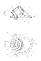
- the Fig. 2 shows an uncut front view of the in Fig. 1 shown assembly.
- This view shows that the bodywork-specific designed reducer 6 housing-like expanded body flange 4 has three fastening tabs 11, 12, 13 for secure mounting of the assembly according to the invention at a steering column opening of a body panel.
- the same components are provided with the same reference numbers.
Abstract
Description
- Die Erfindung betrifft eine Baugruppe zur Abdichtung des Lenksäulendurchbruches in einem zwischen Fahrgastzelle und Motorraum gelegenen Karosserieblech, bestehend aus wenigstens einem Lenksäulenaufnahmelager, wenigstens einem Karosserieblechflansch und wenigstens einer Elastomeraufhängung, über die das Lenksäulenaufnahmelager am Karosserieblechflansch aufgehängt ist.
- Die Abdichtung dient regelmäßig dem Schutz des Motorraumes vor dem Eindringen von Spritzwasser und Verunreinigungen aus dem Inneren des Motorraumes heraus. Dabei gewährleistet das Lenksäulenaufnahmelager die drehbewegliche Aufnahme der Lenkspindel innerhalb des Lenksäulendurchbruches. Die Elastomeraufhängung gewährleistet hingegen eine radialbewegliche Aufnahme der Lenksäule innerhalb des Lenksäulendurchbruches. Außerdem dient die Elastomeraufhängung regelmäßig auch der akustischen Entkopplung einer im Lenksäulenaufnahmelager gehaltenen Lenkspindel von dem im Lenksäulendurchbruch gehaltenen Karosserieblechflansch.
- Da die verschiedenen Fahrzeugmarken, deren Klassen, Typen und Serien eine Vielzahl verschieden ausgebildeter Fahrzeugkarosserien und Lenksäulen hervorbringen, ergibt sich eine ebenso große Anzahl von Lenksäuleneinbausituationen, denen durch die Anfertigung bauserienspezifischer Baugruppen Rechnung getragen wird. Zur Herstellung jeder weiteren bauserienspezifisch ausgebildeten Baugruppe erfordert es jedoch den kostenintensiven Bau weiterer Form- und Fügewerkzeuge, so dass die Herstellungskosten der bekannten Baugruppen nachteilig hoch liegen.
- Der Erfindung liegt die Aufgabe zugrunde, eine Baugruppe der eingangs genannten Gattung aufzuzeigen, deren Herstellungskosten verringert sind.
- Diese Aufgabe ist durch eine Baugruppe mit den Merkmalen des Patentanspruchs 1 gelöst. Vorteilhafte Weiterbildungen sind in den auf den Patentanspruch 1 rückbezogenen Unteransprüchen angegeben.
- Die erfindungsgemäße Baugruppe zeichnet sich dadurch aus, dass der Karosserieblechflansch zu wenigstens einem bauserienspezifisch ausgebildeten Reduzierstück gehäuseartig erweitert ist, und dass die Elastomeraufhängung wenigstens teilweise als bauserienunabhängige Universalaufhängung ausgeführt ist.
- Mit seiner bauserienspezifischen Ausbildung ist das Reduzierstück an die Lenksäulenbausituation einer einzigen oder zumindest weniger verschiedener Fahrzeugserien angepasst. In seiner Funktion als Karosserieblechflansch dient das Reduzierstück einer Reduktion des am Lenksäulendurchbruch bauserienübergreifend ausgebildeten Übermaßes auf ein bauserienspezifisch angepasstes Passmaß. Die gehäuseartige Erweiterung des Reduzierstückes ergibt sich dabei regelmäßig aus einer bauserienspezifischen Anpassung des Reduzierstückes an die bauserienunabhängig und damit universell ausgebildete Elastomeraufhängung. Diese ermöglicht vorteilhaft auch den Einsatz eines bauserienunabhängig ausgebildeten Lenksäulenaufnahmelagers, so dass zur Entwicklung weiterer Bauserien lediglich der Bau eines einfachen Formwerkzeuges für ein verändertes Reduzierstück erforderlich wird. Auf den Bau komplizierter Form- und Fügewerkzeuge für die Herstellung ganzer Baugruppen kann mit Vorteil verzichtet werden.
- Nach einer ersten Weiterbildung der Erfindung sind mit der Elastomeraufhängung wenigstens zwei zwischen dem Reduzierstück und dem Lenksäulenaufnahmelager gelegene Dämpfungskammern ausgebildet. Diese stellen eine besonders wirksame Maßnahme zur Erzeugung von Interferenzen dar, mit denen vom Motorraum in die Dämpfungskammern übertragene Schallwellen einander gegenseitig auslöschen.
- Nach einer nächsten Weiterbildung der Erfindung ist die Elastomeraufhängung aus wenigstens zwei Faltenbalgmodulen zusammengesetzt. Der modulare Aufbau der Elastomeraufhängung ermöglicht vorteilhaft eine einfache und deshalb kostengünstige bauserienspezifische Anpassung an eine veränderte Lenksäuleneinbausituation, da lediglich für das von der Veränderung betroffene Faltenbalgmodul der Bau eines neuen Formwerkzeuges erforderlich ist. Die von der veränderten Lenksäuleneinbausituation unbetroffenen Faltenbalgmodule können vorzugsweise auch in der die veränderte Lenksäuleneinbausituation bedienenden Baugruppe Verwendung finden. Außerdem ermöglicht der modulare Aufbau der Elastomeraufhängung eine besonders einfache und kostengünstige Ausbildung der zwischen dem Reduzierstück und dem Lenksäulenaufnahmelager gelegenen Dämpfungskammern, da auf teurere Formwerkzeuge zur Herstellung doppelwandiger Elastomeraufhängungen verzichtet werden kann.
- Vorzugsweise ist wenigstens eines der Faltenbalgmodule als beidseitig zum Lenksäulenaufnahmelager hin abgedichtete und zwischenliegend zum Reduzierstück hin abgedichtete Axialmanschette ausgebildet. Durch die beidseitige Abdichtung der Axialmanschette zum Lenksäulenaufnahmelager ist eine erste vorzugsweise bauserienunabhängig ausgebildete Dämpfungskammer geschaffen, die über das Reduzierstück im Lenksäulendurchbruch eines Karosseriebleches lediglich mittelbar aufgehängt ist.
- Das als Axialmanschette ausgebildete Faltenbalgmodul ist vorzugsweise ein Universalteil der als Universalaufhängung bauserienunabhängig ausgeführten Elastomeraufhängung. Dazu weist das als Axialmanschette ausgebildete Faltenbalgmodul vorzugsweise eine einfach herstellbare rotationssymmetrische Bauteilgeometrie auf. Grundsätzlich sind hier jedoch auch asymmetrische Bauteilgeometrien denkbar, wenn mit diesen eine verbesserte bauserienspezifische Anpassung des Reduzierstückes an verschiedene Lenksäuleneinbausituationen erreicht ist.
- Nach einer nächsten Weiterbildung der Erfindung ist wenigstens eines der Faltenbalgmodule als innenseitig zum Lenksäulenaufnahmelager hin abgedichtete und außenseitig zum Reduzierstück hin abgedichtete Radialmanschette ausgebildet. Mit der Radialmanschette ist eine unmittelbar an der ersten Dämpfungskammer gelegene zweite jedoch bauserienspezifisch ausgebildete Dämpfungskammer hergestellt, die vorzugsweise bis an die mit einem Karosserieblech zusammenwirkenden Dichtflächen des Reduzierstückes reicht. Zur Befestigung der Radialmanschette am Reduzierstück weist die Radialmanschette mit dem Reduzierstück zusammenwirkende Klemm- oder Raststrukturen auf.
- Da die Längsachsen von Lenksäulen die Öffnungsquerschnitte von Lenksäulendurchbrüchen regelmäßig in einem schiefen Winkel durchlaufen, weist das als Radialmanschette ausgebildete Faltenbalgmodul eine an eine bauserienspezifische Lenksäuleneinbausituation angepasste Winkelgeometrie auf. Grundsätzlich kann das als Radialmanschette ausgebildete Faltenbalgmodul jedoch auch bauserienunabhängig ausgebildet sein, da der modulare Aufbau der Elastomeraufhängung eine kostengünstige Fertigung von Faltenbalgmodulen begünstigt, deren elastische Verformungseigenschaften speziell für einen bauserienunabhängigen Einsatz konzipiert sind.
- Ein Ausführungsbeispiel der Erfindung, aus dem sich weitere erfinderische Merkmale ergeben, ist in der Zeichnung darstellt. Es zeigen:
- Fig. 1
- eine Seitenansicht einer erfindungsgemäßen Baugruppe im Mittelschnitt; und
- Fig. 2
- eine ungeschnittene Vorderansicht der Baugruppe gemäß
Fig. 1 . - Die
Fig. 1 zeigt die erfindungsgemäße Baugruppe zur Abdichtung eines Lenksäulendurchbruches in einem zwischen Fahrgastzelle und Motorraum gelegenen Karosserieblech. Die Baugruppe besteht aus einem Lenksäulenaufnahmelager 1 mit zwei Gleitbuchsen 2, 3, einem Karosserieblechflansch 4 und einer Elastomeraufhängung 5, über die das Lenksäulenaufnahmelager 1 am Karosserieblechflansch 4 aufgehängt ist. Der Karosserieblechflansch 4 ist zu einem bauserienspezifisch ausgebildeten Reduzierstück 6 gehäuseartig erweitert, so dass die Elastomeraufhängung 5 teilweise als bauserienunabhängige Universalaufhängung ausgeführt ist. Dazu ist die Elastomeraufhängung 5 aus zwei Faltenbalgmodulen 7, 8 zusammengesetzt, mit denen zwei im Ringspalt zwischen dem Reduzierstück 6 und dem Lenksäulenaufnahmelager 1 hintereinander gelegene Dämpfungskammern 9, 10 ausgebildet sind. Während das Faltenbalgmodul 7 als beidseitig zum Lenksäulenaufnahmelager 1 hin abgedichtete und zwischenliegend zum Reduzierstück 6 hin abgedichtete Axialmanschette ausgebildet ist, ist das andere Faltenbalgmodul 8 als innenseitig zum Lenksäulenaufnahmelager 1 hin abgedichtete und außenseitig zum Reduzierstück 6 hin abgedichtete Radialmanschette ausgebildet. Das als Axialmanschette ausgebildete Faltenbalgmodul 7 ist als Universalteil der bauserienunabhängig ausgebildeten Elastomeraufhängung 5 ausgeführt und weist eine einfache rotationssymmetrische Bauteilgeometrie auf. Das als Radialmanschette ausgebildete Faltenbalgmodul weist hingegen eine an eine bauserienspezifische Lenksäuleneinbausituation angepasste Winkelgeometrie auf. Eine derartige Winkelgeometrie weist auch das bauserienspezifisch ausgebildete Reduzierstück 6 auf. - Die
Fig. 2 zeigt eine ungeschnittene Vorderansicht der inFig. 1 dargestellten Baugruppe. Diese Ansicht lässt erkennen, dass der zu dem bauserienspezifisch ausgebildeten Reduzierstück 6 gehäuseartig erweiterte Karosserieblechflansch 4 drei Befestigungslaschen 11, 12, 13 zur sicheren Montage der erfindungsgemäßen Baugruppe an einem Lenksäulendurchbruch eines Karosseriebleches aufweist. Gleiche Bauteile sind mit gleichen Bezugszahlen versehen. - Alle in der vorstehenden Beschreibung und in den Ansprüchen genannten Merkmale sind in einer beliebigen Auswahl mit den Merkmalen des unabhängigen Anspruchs kombinierbar. Die Offenbarung der Erfindung ist somit nicht auf die beschriebenen bzw. beanspruchten Merkmalskombinationen beschränkt, vielmehr sind alle im Rahmen der Erfindung sinnvollen Merkmalskombinationen als offenbart zu betrachten.
Claims (8)
- Baugruppe zur Abdichtung des Lenksäulendurchbruches in einem zwischen Fahrgastzelle und Motorraum gelegenen Karosserieblech, bestehend aus wenigstens einem Lenksäulenaufnahmelager, wenigstens einem Karosserieblechflansch und wenigstens einer Elastomeraufhängung, über die das Lenksäulenaufnahmelager am Karosserieblechflansch aufgehängt ist,
dadurch gekennzeichnet,
dass der Karosserieblechflansch (4) zu wenigstens einem bauserienspezifisch ausgebildeten Reduzierstück (6) gehäuseartig erweitert ist, und
dass die Elastomeraufhängung (5) wenigstens teilweise als bauserienunabhängige Universallaufhängung ausgeführt ist. - Baugruppe nach Anspruch 1, dadurch gekennzeichnet, dass mit der Elastomeraufhängung (5) wenigstens zwei zwischen dem Reduzierstück (6) und dem Lenksäulenaufnahmelager (1) gelegene Dämpfungskammern (9, 10) ausgebildet sind.
- Baugruppe nach Anspruch 2, dadurch gekennzeichnet, dass die Elastomeraufhängung (5) aus wenigstens zwei Faltenbalgmodulen (7, 8) zusammengesetzt ist.
- Baugruppe nach Anspruch 3, dadurch gekennzeichnet, dass wenigstens eines der Faltenbalgmodule (7, 8) als beidseitig zum Lenksäulenaufnahmelager (1) hin und zwischenliegend zum Reduzierstück (6) hin abgedichtete Axialmanschette ausgebildet ist.
- Baugruppe nach Anspruch 4, dadurch gekennzeichnet, dass wenigstens das als Axialmanschette ausgebildete Faltenbalgmodul (7) als ein Universalteil der bauserienunabhängigen Universalaufhängung ausgeführt ist.
- Baugruppe nach Anspruch 4 oder 5, dadurch gekennzeichnet, dass das als Axialmanschette ausgebildete Faltenbalgmodul (7) eine rotationssymmetrische Bauteilgeometrie aufweist.
- Baugruppe nach einem der Ansprüche 3 bis 6, dadurch gekennzeichnet, dass wenigstens eines der Faltenbalgmodule (7, 8) als innenseitig zum Lenksäulenaufnahmelager (1) hin und außenseitig zum Reduzierstück (6) hin abgedichtete Radialmanschette ausgebildet ist.
- Baugruppe nach Anspruch 7, dadurch gekennzeichnet, dass das als Radialmanschette ausgebildete Faltenbalgmodul (8) eine an eine bauserienspezifische Lenksäuleneinbausituation angepasste Winkelgeometrie aufweist.
Applications Claiming Priority (1)
| Application Number | Priority Date | Filing Date | Title |
|---|---|---|---|
| DE102013014046.3A DE102013014046A1 (de) | 2013-08-22 | 2013-08-22 | Baugruppe zur Abdichtung eines Lenksäulendurchbruches |
Publications (2)
| Publication Number | Publication Date |
|---|---|
| EP2842832A1 true EP2842832A1 (de) | 2015-03-04 |
| EP2842832B1 EP2842832B1 (de) | 2017-10-18 |
Family
ID=51383611
Family Applications (1)
| Application Number | Title | Priority Date | Filing Date |
|---|---|---|---|
| EP14181630.6A Active EP2842832B1 (de) | 2013-08-22 | 2014-08-20 | Baugruppe zur Abdichtung eines Lenksäulendurchbruches |
Country Status (4)
| Country | Link |
|---|---|
| US (1) | US9644749B2 (de) |
| EP (1) | EP2842832B1 (de) |
| CN (1) | CN104417598B (de) |
| DE (1) | DE102013014046A1 (de) |
Cited By (3)
| Publication number | Priority date | Publication date | Assignee | Title |
|---|---|---|---|---|
| CN111361629A (zh) * | 2020-02-27 | 2020-07-03 | 北汽福田汽车股份有限公司 | 转向管柱的转向轴护罩组件、转向管柱总成及车辆 |
| EP3750780A1 (de) * | 2019-06-12 | 2020-12-16 | Etimex Technical Components GmbH | Lenksäulendurchführung eines lenkbaren fahrzeugs |
| EP4194276A1 (de) * | 2021-12-08 | 2023-06-14 | DAF Trucks N.V. | Lastkraftwagen mit einer formdichtungsvorrichtung und verfahren zur herstellung der formdichtungsvorrichtung |
Families Citing this family (7)
| Publication number | Priority date | Publication date | Assignee | Title |
|---|---|---|---|---|
| KR101878997B1 (ko) * | 2013-11-08 | 2018-07-17 | 주식회사 만도 | 자동차의 조향장치 |
| DE102016206723A1 (de) * | 2016-04-20 | 2017-10-26 | Thyssenkrupp Ag | Dichtungsvorrichtung |
| KR101819143B1 (ko) * | 2016-12-13 | 2018-02-28 | 주식회사 디엠씨 | 베어링이 구비된 일체형 더스트 커버 |
| US10995859B2 (en) * | 2018-04-26 | 2021-05-04 | Honda Motor Co., Ltd. | Thermally actuated grommet |
| WO2021007739A1 (en) * | 2019-07-15 | 2021-01-21 | Psa Automobiles Sa | Mounting of a sealing element of an input shaft of a steering rack in a vehicle |
| JP7351192B2 (ja) | 2019-11-20 | 2023-09-27 | 日本精工株式会社 | ダストカバー |
| US11142237B2 (en) | 2020-01-14 | 2021-10-12 | Honda Motor Co., Ltd. | Tilt steering assembly for a vehicle |
Citations (4)
| Publication number | Priority date | Publication date | Assignee | Title |
|---|---|---|---|---|
| EP1538377A1 (de) * | 2002-09-10 | 2005-06-08 | NSK Ltd. | Lochabdeckung für kraftfahrzeug |
| JP2007022323A (ja) * | 2005-07-15 | 2007-02-01 | Inoac Corp | コラムホールカバー |
| DE102006053265A1 (de) * | 2006-11-11 | 2008-05-15 | Daimler Ag | Dichtungsanordnung zur Abdichtung einer Durchgangsöffnung und Montageverfahren |
| JP2012017059A (ja) * | 2010-07-09 | 2012-01-26 | Kinugawa Rubber Ind Co Ltd | シャフトシールの取付構造 |
Family Cites Families (7)
| Publication number | Priority date | Publication date | Assignee | Title |
|---|---|---|---|---|
| DE3709027C1 (de) * | 1987-03-19 | 1988-01-21 | Daimler Benz Ag | Dichtmanschette |
| US6056297A (en) * | 1998-04-24 | 2000-05-02 | General Motors Corporation | Intermediate shaft dash panel seal |
| DE19857392A1 (de) * | 1998-12-12 | 2000-06-21 | Daimler Chrysler Ag | Dichtungsanordnung |
| US7371181B2 (en) * | 2003-08-01 | 2008-05-13 | Delphi Technologies, Inc. | Sealing system for constant velocity joint |
| CN1910076B (zh) * | 2004-01-15 | 2013-04-24 | 日本精工株式会社 | 转向轴用防尘罩 |
| DE102007052721B4 (de) * | 2007-11-06 | 2013-05-16 | Hübner GmbH | Vorrichtung zur Abdichtung des Übergangs der Lenkwelle zum Fahrerhaus eines Lkws |
| US8469399B2 (en) * | 2011-09-01 | 2013-06-25 | GM Global Technology Operations LLC | Interlocking seal |
-
2013
- 2013-08-22 DE DE102013014046.3A patent/DE102013014046A1/de not_active Withdrawn
-
2014
- 2014-08-20 EP EP14181630.6A patent/EP2842832B1/de active Active
- 2014-08-21 CN CN201410416121.4A patent/CN104417598B/zh active Active
- 2014-08-22 US US14/466,740 patent/US9644749B2/en active Active
Patent Citations (4)
| Publication number | Priority date | Publication date | Assignee | Title |
|---|---|---|---|---|
| EP1538377A1 (de) * | 2002-09-10 | 2005-06-08 | NSK Ltd. | Lochabdeckung für kraftfahrzeug |
| JP2007022323A (ja) * | 2005-07-15 | 2007-02-01 | Inoac Corp | コラムホールカバー |
| DE102006053265A1 (de) * | 2006-11-11 | 2008-05-15 | Daimler Ag | Dichtungsanordnung zur Abdichtung einer Durchgangsöffnung und Montageverfahren |
| JP2012017059A (ja) * | 2010-07-09 | 2012-01-26 | Kinugawa Rubber Ind Co Ltd | シャフトシールの取付構造 |
Cited By (4)
| Publication number | Priority date | Publication date | Assignee | Title |
|---|---|---|---|---|
| EP3750780A1 (de) * | 2019-06-12 | 2020-12-16 | Etimex Technical Components GmbH | Lenksäulendurchführung eines lenkbaren fahrzeugs |
| CN111361629A (zh) * | 2020-02-27 | 2020-07-03 | 北汽福田汽车股份有限公司 | 转向管柱的转向轴护罩组件、转向管柱总成及车辆 |
| EP4194276A1 (de) * | 2021-12-08 | 2023-06-14 | DAF Trucks N.V. | Lastkraftwagen mit einer formdichtungsvorrichtung und verfahren zur herstellung der formdichtungsvorrichtung |
| NL2030072B1 (en) * | 2021-12-08 | 2023-06-22 | Daf Trucks Nv | Moulded sealing device, truck comprising the moulded sealing device, and method for manufacturing the moulded sealing device |
Also Published As
| Publication number | Publication date |
|---|---|
| US20150054231A1 (en) | 2015-02-26 |
| EP2842832B1 (de) | 2017-10-18 |
| CN104417598A (zh) | 2015-03-18 |
| US9644749B2 (en) | 2017-05-09 |
| CN104417598B (zh) | 2018-04-13 |
| DE102013014046A1 (de) | 2015-02-26 |
Similar Documents
| Publication | Publication Date | Title |
|---|---|---|
| EP2842832B1 (de) | Baugruppe zur Abdichtung eines Lenksäulendurchbruches | |
| DE19624886C2 (de) | Flüssigkeitsdämpfungsvorrichtung mit unterschiedlich großen Federsteifigkeitswerten in zwei zueinander senkrechten Richtungen | |
| EP3181390B1 (de) | Fahrzeug mit einem antriebsaggregat und einer aggregatelagerung | |
| DE102007012958A1 (de) | Lagervorrichtung zur schwingungsentkoppelten Drehlagerung einer Zwischenwelle am Motorblock eines Kfz und Verfahren zur schwingungsentkoppelten Drehlagerung einer Zwischenwelle am Motorblock eines Kfz | |
| DE102011056013A1 (de) | Mehrteiliges Führungslager zum Einsatz in einem Kfz-Lagerbock | |
| DE102006035583A1 (de) | Vorrichtung zur Halterung eines elektrischen Gebläse-Antriebsmotors am Gehäuse einer Heiz-, Lüftungs- und/oder Klimaanlage für Fahrzeuge | |
| DE102015204046A1 (de) | Dynamischer Dämpfer | |
| DE102013222727A1 (de) | Federbeinlager | |
| DE102018131998A1 (de) | Aggregate-Befestigungseinrichtung zum schwingfähigen Festlegen eines Aggregats eines elektrischen Antriebs in einem Kraftfahrzeug | |
| DE102016113997A1 (de) | Entkoppler für ein hydraulisches Motorlager | |
| DE102006027806A1 (de) | Federbeinlager | |
| DE102015012928B4 (de) | Schwingungstilger und Achsträger mit demselben | |
| DE202006008365U1 (de) | Wellenlager, insbesondere Gelenkwellenlager | |
| EP0681117A1 (de) | Lageranordnung | |
| DE102014102408B3 (de) | Lenkwelle für ein Kraftfahrzeug | |
| DE102016206013A1 (de) | Dichtungsanordnung eines Radlagers | |
| DE102011004422A1 (de) | Radlagereinheit mit Schutzkappe | |
| DE102012025583B4 (de) | Kraftfahrzeug mit einem Schallerzeugungssystem zur Erzeugung eines künstlichen Motorengeräusches | |
| WO2019166198A1 (de) | Antriebsanordnung für ein schienenfahrzeug | |
| DE102017005503A1 (de) | Wälzlager sowie Kraftfahrzeug | |
| DE102007012070A1 (de) | Lageranordnung für eine Kolbenstange eines Schwingungsdämpfers | |
| DE102014222769B4 (de) | Ausgleichselement zum Ausgleichen von Toleranzen, Baugruppe, Lenkungslager und Fahrzeuglenkung mit einem Ausgleichselement | |
| DE102006053263A1 (de) | Dichtungsmanschette und Dichtungsanordnung | |
| DE102015224149A1 (de) | Hydraulische Lagerbuchse | |
| DE102015208473A1 (de) | Gebläseeinrichtung |
Legal Events
| Date | Code | Title | Description |
|---|---|---|---|
| 17P | Request for examination filed |
Effective date: 20140820 |
|
| AK | Designated contracting states |
Kind code of ref document: A1 Designated state(s): AL AT BE BG CH CY CZ DE DK EE ES FI FR GB GR HR HU IE IS IT LI LT LU LV MC MK MT NL NO PL PT RO RS SE SI SK SM TR |
|
| AX | Request for extension of the european patent |
Extension state: BA ME |
|
| PUAI | Public reference made under article 153(3) epc to a published international application that has entered the european phase |
Free format text: ORIGINAL CODE: 0009012 |
|
| R17P | Request for examination filed (corrected) |
Effective date: 20150729 |
|
| RBV | Designated contracting states (corrected) |
Designated state(s): AL AT BE BG CH CY CZ DE DK EE ES FI FR GB GR HR HU IE IS IT LI LT LU LV MC MK MT NL NO PL PT RO RS SE SI SK SM TR |
|
| RIC1 | Information provided on ipc code assigned before grant |
Ipc: F16J 15/52 20060101ALI20170322BHEP Ipc: B62D 1/16 20060101AFI20170322BHEP |
|
| GRAP | Despatch of communication of intention to grant a patent |
Free format text: ORIGINAL CODE: EPIDOSNIGR1 |
|
| INTG | Intention to grant announced |
Effective date: 20170508 |
|
| GRAS | Grant fee paid |
Free format text: ORIGINAL CODE: EPIDOSNIGR3 |
|
| GRAA | (expected) grant |
Free format text: ORIGINAL CODE: 0009210 |
|
| AK | Designated contracting states |
Kind code of ref document: B1 Designated state(s): AL AT BE BG CH CY CZ DE DK EE ES FI FR GB GR HR HU IE IS IT LI LT LU LV MC MK MT NL NO PL PT RO RS SE SI SK SM TR |
|
| REG | Reference to a national code |
Ref country code: GB Ref legal event code: FG4D Free format text: NOT ENGLISH |
|
| REG | Reference to a national code |
Ref country code: CH Ref legal event code: EP |
|
| REG | Reference to a national code |
Ref country code: AT Ref legal event code: REF Ref document number: 937666 Country of ref document: AT Kind code of ref document: T Effective date: 20171115 Ref country code: IE Ref legal event code: FG4D Free format text: LANGUAGE OF EP DOCUMENT: GERMAN |
|
| REG | Reference to a national code |
Ref country code: DE Ref legal event code: R096 Ref document number: 502014005840 Country of ref document: DE |
|
| REG | Reference to a national code |
Ref country code: NL Ref legal event code: MP Effective date: 20171018 |
|
| REG | Reference to a national code |
Ref country code: LT Ref legal event code: MG4D |
|
| PG25 | Lapsed in a contracting state [announced via postgrant information from national office to epo] |
Ref country code: NL Free format text: LAPSE BECAUSE OF FAILURE TO SUBMIT A TRANSLATION OF THE DESCRIPTION OR TO PAY THE FEE WITHIN THE PRESCRIBED TIME-LIMIT Effective date: 20171018 |
|
| PG25 | Lapsed in a contracting state [announced via postgrant information from national office to epo] |
Ref country code: LT Free format text: LAPSE BECAUSE OF FAILURE TO SUBMIT A TRANSLATION OF THE DESCRIPTION OR TO PAY THE FEE WITHIN THE PRESCRIBED TIME-LIMIT Effective date: 20171018 Ref country code: NO Free format text: LAPSE BECAUSE OF FAILURE TO SUBMIT A TRANSLATION OF THE DESCRIPTION OR TO PAY THE FEE WITHIN THE PRESCRIBED TIME-LIMIT Effective date: 20180118 Ref country code: SE Free format text: LAPSE BECAUSE OF FAILURE TO SUBMIT A TRANSLATION OF THE DESCRIPTION OR TO PAY THE FEE WITHIN THE PRESCRIBED TIME-LIMIT Effective date: 20171018 Ref country code: ES Free format text: LAPSE BECAUSE OF FAILURE TO SUBMIT A TRANSLATION OF THE DESCRIPTION OR TO PAY THE FEE WITHIN THE PRESCRIBED TIME-LIMIT Effective date: 20171018 Ref country code: FI Free format text: LAPSE BECAUSE OF FAILURE TO SUBMIT A TRANSLATION OF THE DESCRIPTION OR TO PAY THE FEE WITHIN THE PRESCRIBED TIME-LIMIT Effective date: 20171018 |
|
| PG25 | Lapsed in a contracting state [announced via postgrant information from national office to epo] |
Ref country code: IS Free format text: LAPSE BECAUSE OF FAILURE TO SUBMIT A TRANSLATION OF THE DESCRIPTION OR TO PAY THE FEE WITHIN THE PRESCRIBED TIME-LIMIT Effective date: 20180218 Ref country code: GR Free format text: LAPSE BECAUSE OF FAILURE TO SUBMIT A TRANSLATION OF THE DESCRIPTION OR TO PAY THE FEE WITHIN THE PRESCRIBED TIME-LIMIT Effective date: 20180119 Ref country code: HR Free format text: LAPSE BECAUSE OF FAILURE TO SUBMIT A TRANSLATION OF THE DESCRIPTION OR TO PAY THE FEE WITHIN THE PRESCRIBED TIME-LIMIT Effective date: 20171018 Ref country code: LV Free format text: LAPSE BECAUSE OF FAILURE TO SUBMIT A TRANSLATION OF THE DESCRIPTION OR TO PAY THE FEE WITHIN THE PRESCRIBED TIME-LIMIT Effective date: 20171018 Ref country code: BG Free format text: LAPSE BECAUSE OF FAILURE TO SUBMIT A TRANSLATION OF THE DESCRIPTION OR TO PAY THE FEE WITHIN THE PRESCRIBED TIME-LIMIT Effective date: 20180118 Ref country code: RS Free format text: LAPSE BECAUSE OF FAILURE TO SUBMIT A TRANSLATION OF THE DESCRIPTION OR TO PAY THE FEE WITHIN THE PRESCRIBED TIME-LIMIT Effective date: 20171018 |
|
| REG | Reference to a national code |
Ref country code: DE Ref legal event code: R097 Ref document number: 502014005840 Country of ref document: DE |
|
| PG25 | Lapsed in a contracting state [announced via postgrant information from national office to epo] |
Ref country code: DK Free format text: LAPSE BECAUSE OF FAILURE TO SUBMIT A TRANSLATION OF THE DESCRIPTION OR TO PAY THE FEE WITHIN THE PRESCRIBED TIME-LIMIT Effective date: 20171018 Ref country code: CZ Free format text: LAPSE BECAUSE OF FAILURE TO SUBMIT A TRANSLATION OF THE DESCRIPTION OR TO PAY THE FEE WITHIN THE PRESCRIBED TIME-LIMIT Effective date: 20171018 Ref country code: SK Free format text: LAPSE BECAUSE OF FAILURE TO SUBMIT A TRANSLATION OF THE DESCRIPTION OR TO PAY THE FEE WITHIN THE PRESCRIBED TIME-LIMIT Effective date: 20171018 Ref country code: EE Free format text: LAPSE BECAUSE OF FAILURE TO SUBMIT A TRANSLATION OF THE DESCRIPTION OR TO PAY THE FEE WITHIN THE PRESCRIBED TIME-LIMIT Effective date: 20171018 |
|
| PLBE | No opposition filed within time limit |
Free format text: ORIGINAL CODE: 0009261 |
|
| STAA | Information on the status of an ep patent application or granted ep patent |
Free format text: STATUS: NO OPPOSITION FILED WITHIN TIME LIMIT |
|
| PG25 | Lapsed in a contracting state [announced via postgrant information from national office to epo] |
Ref country code: PL Free format text: LAPSE BECAUSE OF FAILURE TO SUBMIT A TRANSLATION OF THE DESCRIPTION OR TO PAY THE FEE WITHIN THE PRESCRIBED TIME-LIMIT Effective date: 20171018 Ref country code: RO Free format text: LAPSE BECAUSE OF FAILURE TO SUBMIT A TRANSLATION OF THE DESCRIPTION OR TO PAY THE FEE WITHIN THE PRESCRIBED TIME-LIMIT Effective date: 20171018 Ref country code: SM Free format text: LAPSE BECAUSE OF FAILURE TO SUBMIT A TRANSLATION OF THE DESCRIPTION OR TO PAY THE FEE WITHIN THE PRESCRIBED TIME-LIMIT Effective date: 20171018 Ref country code: IT Free format text: LAPSE BECAUSE OF FAILURE TO SUBMIT A TRANSLATION OF THE DESCRIPTION OR TO PAY THE FEE WITHIN THE PRESCRIBED TIME-LIMIT Effective date: 20171018 |
|
| 26N | No opposition filed |
Effective date: 20180719 |
|
| PG25 | Lapsed in a contracting state [announced via postgrant information from national office to epo] |
Ref country code: MT Free format text: LAPSE BECAUSE OF FAILURE TO SUBMIT A TRANSLATION OF THE DESCRIPTION OR TO PAY THE FEE WITHIN THE PRESCRIBED TIME-LIMIT Effective date: 20171018 |
|
| PG25 | Lapsed in a contracting state [announced via postgrant information from national office to epo] |
Ref country code: SI Free format text: LAPSE BECAUSE OF FAILURE TO SUBMIT A TRANSLATION OF THE DESCRIPTION OR TO PAY THE FEE WITHIN THE PRESCRIBED TIME-LIMIT Effective date: 20171018 |
|
| PG25 | Lapsed in a contracting state [announced via postgrant information from national office to epo] |
Ref country code: MC Free format text: LAPSE BECAUSE OF FAILURE TO SUBMIT A TRANSLATION OF THE DESCRIPTION OR TO PAY THE FEE WITHIN THE PRESCRIBED TIME-LIMIT Effective date: 20171018 |
|
| REG | Reference to a national code |
Ref country code: CH Ref legal event code: PL |
|
| GBPC | Gb: european patent ceased through non-payment of renewal fee |
Effective date: 20180820 |
|
| PG25 | Lapsed in a contracting state [announced via postgrant information from national office to epo] |
Ref country code: LU Free format text: LAPSE BECAUSE OF NON-PAYMENT OF DUE FEES Effective date: 20180820 Ref country code: LI Free format text: LAPSE BECAUSE OF NON-PAYMENT OF DUE FEES Effective date: 20180831 Ref country code: CH Free format text: LAPSE BECAUSE OF NON-PAYMENT OF DUE FEES Effective date: 20180831 |
|
| REG | Reference to a national code |
Ref country code: BE Ref legal event code: MM Effective date: 20180831 |
|
| REG | Reference to a national code |
Ref country code: IE Ref legal event code: MM4A |
|
| PG25 | Lapsed in a contracting state [announced via postgrant information from national office to epo] |
Ref country code: IE Free format text: LAPSE BECAUSE OF NON-PAYMENT OF DUE FEES Effective date: 20180820 |
|
| PG25 | Lapsed in a contracting state [announced via postgrant information from national office to epo] |
Ref country code: BE Free format text: LAPSE BECAUSE OF NON-PAYMENT OF DUE FEES Effective date: 20180831 Ref country code: FR Free format text: LAPSE BECAUSE OF NON-PAYMENT OF DUE FEES Effective date: 20180831 |
|
| PG25 | Lapsed in a contracting state [announced via postgrant information from national office to epo] |
Ref country code: GB Free format text: LAPSE BECAUSE OF NON-PAYMENT OF DUE FEES Effective date: 20180820 |
|
| REG | Reference to a national code |
Ref country code: DE Ref legal event code: R082 Ref document number: 502014005840 Country of ref document: DE Representative=s name: BARDEHLE PAGENBERG PARTNERSCHAFT MBB PATENTANW, DE |
|
| PG25 | Lapsed in a contracting state [announced via postgrant information from national office to epo] |
Ref country code: TR Free format text: LAPSE BECAUSE OF FAILURE TO SUBMIT A TRANSLATION OF THE DESCRIPTION OR TO PAY THE FEE WITHIN THE PRESCRIBED TIME-LIMIT Effective date: 20171018 |
|
| PG25 | Lapsed in a contracting state [announced via postgrant information from national office to epo] |
Ref country code: PT Free format text: LAPSE BECAUSE OF FAILURE TO SUBMIT A TRANSLATION OF THE DESCRIPTION OR TO PAY THE FEE WITHIN THE PRESCRIBED TIME-LIMIT Effective date: 20171018 Ref country code: HU Free format text: LAPSE BECAUSE OF FAILURE TO SUBMIT A TRANSLATION OF THE DESCRIPTION OR TO PAY THE FEE WITHIN THE PRESCRIBED TIME-LIMIT; INVALID AB INITIO Effective date: 20140820 |
|
| PG25 | Lapsed in a contracting state [announced via postgrant information from national office to epo] |
Ref country code: MK Free format text: LAPSE BECAUSE OF NON-PAYMENT OF DUE FEES Effective date: 20171018 Ref country code: CY Free format text: LAPSE BECAUSE OF FAILURE TO SUBMIT A TRANSLATION OF THE DESCRIPTION OR TO PAY THE FEE WITHIN THE PRESCRIBED TIME-LIMIT Effective date: 20171018 |
|
| PG25 | Lapsed in a contracting state [announced via postgrant information from national office to epo] |
Ref country code: AL Free format text: LAPSE BECAUSE OF FAILURE TO SUBMIT A TRANSLATION OF THE DESCRIPTION OR TO PAY THE FEE WITHIN THE PRESCRIBED TIME-LIMIT Effective date: 20171018 |
|
| REG | Reference to a national code |
Ref country code: AT Ref legal event code: MM01 Ref document number: 937666 Country of ref document: AT Kind code of ref document: T Effective date: 20190820 |
|
| PG25 | Lapsed in a contracting state [announced via postgrant information from national office to epo] |
Ref country code: AT Free format text: LAPSE BECAUSE OF NON-PAYMENT OF DUE FEES Effective date: 20190820 |
|
| REG | Reference to a national code |
Ref country code: DE Ref legal event code: R082 Ref document number: 502014005840 Country of ref document: DE Representative=s name: BARDEHLE PAGENBERG PARTNERSCHAFT MBB PATENTANW, DE Ref country code: DE Ref legal event code: R082 Ref document number: 502014005840 Country of ref document: DE |
|
| REG | Reference to a national code |
Ref country code: DE Ref legal event code: R081 Ref document number: 502014005840 Country of ref document: DE Owner name: RUESTER GMBH, DE Free format text: FORMER OWNER: HENNIGES AUTOMOTIVE GMBH & CO. KG, 31547 REHBURG-LOCCUM, DE Ref country code: DE Ref legal event code: R082 Ref document number: 502014005840 Country of ref document: DE Representative=s name: BARDEHLE PAGENBERG PARTNERSCHAFT MBB PATENTANW, DE Ref country code: DE Ref legal event code: R081 Ref document number: 502014005840 Country of ref document: DE Owner name: BAYRAK TECHNIK GMBH, DE Free format text: FORMER OWNER: HENNIGES AUTOMOTIVE GMBH & CO. KG, 31547 REHBURG-LOCCUM, DE |
|
| REG | Reference to a national code |
Ref country code: DE Ref legal event code: R082 Ref document number: 502014005840 Country of ref document: DE Ref country code: DE Ref legal event code: R082 Ref document number: 502014005840 Country of ref document: DE Representative=s name: BARDEHLE PAGENBERG PARTNERSCHAFT MBB PATENTANW, DE |
|
| REG | Reference to a national code |
Ref country code: DE Ref legal event code: R081 Ref document number: 502014005840 Country of ref document: DE Owner name: BAYRAK TECHNIK GMBH, DE Free format text: FORMER OWNER: RUESTER GMBH, 31547 REHBURG-LOCCUM, DE Ref country code: DE Ref legal event code: R082 Ref document number: 502014005840 Country of ref document: DE Representative=s name: BARDEHLE PAGENBERG PARTNERSCHAFT MBB PATENTANW, DE |
|
| PGFP | Annual fee paid to national office [announced via postgrant information from national office to epo] |
Ref country code: DE Payment date: 20230825 Year of fee payment: 10 |