EP2839900A1 - Procédé et dispositif de fabrication d'une section de raccordement pourvue d'une face terminale comme élément d'un outil - Google Patents
Procédé et dispositif de fabrication d'une section de raccordement pourvue d'une face terminale comme élément d'un outil Download PDFInfo
- Publication number
- EP2839900A1 EP2839900A1 EP14161805.8A EP14161805A EP2839900A1 EP 2839900 A1 EP2839900 A1 EP 2839900A1 EP 14161805 A EP14161805 A EP 14161805A EP 2839900 A1 EP2839900 A1 EP 2839900A1
- Authority
- EP
- European Patent Office
- Prior art keywords
- connecting portion
- longitudinal
- face
- drill
- groove
- Prior art date
- Legal status (The legal status is an assumption and is not a legal conclusion. Google has not performed a legal analysis and makes no representation as to the accuracy of the status listed.)
- Granted
Links
- 238000000034 method Methods 0.000 title claims abstract description 44
- 238000004519 manufacturing process Methods 0.000 title claims abstract description 15
- 239000011265 semifinished product Substances 0.000 claims abstract description 13
- 238000004049 embossing Methods 0.000 claims description 13
- 239000000463 material Substances 0.000 claims description 6
- 238000001125 extrusion Methods 0.000 claims description 5
- 230000002093 peripheral effect Effects 0.000 claims description 4
- 239000000945 filler Substances 0.000 claims description 3
- 230000015572 biosynthetic process Effects 0.000 claims description 2
- 238000005755 formation reaction Methods 0.000 claims description 2
- 238000000465 moulding Methods 0.000 claims description 2
- 238000012856 packing Methods 0.000 claims description 2
- 238000011144 upstream manufacturing Methods 0.000 claims description 2
- 238000007373 indentation Methods 0.000 claims 1
- 239000000543 intermediate Substances 0.000 description 3
- 239000013067 intermediate product Substances 0.000 description 3
- 238000005242 forging Methods 0.000 description 2
- 238000007493 shaping process Methods 0.000 description 2
- 230000007704 transition Effects 0.000 description 2
- 238000006243 chemical reaction Methods 0.000 description 1
- 238000005520 cutting process Methods 0.000 description 1
- 230000007547 defect Effects 0.000 description 1
- 238000005553 drilling Methods 0.000 description 1
- 238000005538 encapsulation Methods 0.000 description 1
- 210000003746 feather Anatomy 0.000 description 1
- 238000010438 heat treatment Methods 0.000 description 1
- 239000002184 metal Substances 0.000 description 1
- 239000002991 molded plastic Substances 0.000 description 1
- 230000035515 penetration Effects 0.000 description 1
- 239000004033 plastic Substances 0.000 description 1
- 239000000047 product Substances 0.000 description 1
- 230000002787 reinforcement Effects 0.000 description 1
Images


Classifications
-
- B—PERFORMING OPERATIONS; TRANSPORTING
- B21—MECHANICAL METAL-WORKING WITHOUT ESSENTIALLY REMOVING MATERIAL; PUNCHING METAL
- B21K—MAKING FORGED OR PRESSED METAL PRODUCTS, e.g. HORSE-SHOES, RIVETS, BOLTS OR WHEELS
- B21K5/00—Making tools or tool parts, e.g. pliers
- B21K5/02—Making tools or tool parts, e.g. pliers drilling-tools or other for making or working on holes
- B21K5/10—Forming drill-bit shanks
-
- B—PERFORMING OPERATIONS; TRANSPORTING
- B21—MECHANICAL METAL-WORKING WITHOUT ESSENTIALLY REMOVING MATERIAL; PUNCHING METAL
- B21J—FORGING; HAMMERING; PRESSING METAL; RIVETING; FORGE FURNACES
- B21J5/00—Methods for forging, hammering, or pressing; Special equipment or accessories therefor
- B21J5/06—Methods for forging, hammering, or pressing; Special equipment or accessories therefor for performing particular operations
- B21J5/12—Forming profiles on internal or external surfaces
Definitions
- the invention relates to a method for producing a connection area provided with an end face by embossing as part of a tool, in particular a drill or bit axially movably mounted in the tool holder of a hammer drill, or as part of a connecting rod, wherein the connecting portion has at least one longitudinal groove or longitudinal surface, of which at least one is at least partially closed to the end face of the connecting portion.
- the invention further relates to a semi-tool, a drill, a chisel or a rod with a connecting portion and / or a front working portion.
- the invention further relates to a rod for absorbing axial tensile and compressive forces and torques.
- the invention further relates to a device for producing a connecting portion as part of a tool, in particular an axially movably mounted in the tool holder of a hammer drill or chisel by imprinting.
- the invention also relates to a combination of dies for the production of connecting portions for half tools, drills, chisels and rods with at least two longitudinal grooves or longitudinal surfaces, at least one of which is at least partially closed to the end surface of the connecting portion.
- the object of the invention is therefore to provide an improved method and an improved apparatus for producing connecting sections for bars, drills and chisels.
- the invention includes the recognition that drills and connecting rods are usually manufactured on cutting machine tools, which leads to an increased material consumption due to the resulting chips and also requires relatively long production times. Therefore, there have always been considerations to produce such connection sections by forming.
- a method for producing a rod and a rod is described, which can be used for example as a pendulum support for a chassis in the automotive industry.
- the EP 2 181 783 B1 proposed rod is not suitable for higher axial tensile forces, since the undercut obtained at warmer temperatures is not sufficient resistance to a molded plastic part. Since the transition from the thinner cylindrical part to the compressed thicker section is also continuous, this transition does not provide a clearly delimiting stop. Only the in FIG.
- a drill semi-finished product or a rod with a substantially cylindrical or polygonal, in particular square, circumferential surface is provided in a step a).
- the connecting portion is inserted into a closing die.
- the at least one longitudinal groove is impressed by radial infeed of one or more reshaping bodies movable in the closing die, whereby an elongation of the connecting portion and in the region of the longitudinal groove a cross-sectional area reduction is effected.
- the term "elongation" is to be understood as a change in length, in particular an increase in the length of the drill semi-finished product in a longitudinal direction.
- the cross-sectional area reduction can be understood on the one hand as a reduction of the cross-sectional area in the region of the longitudinal groove transversely to a longitudinal direction of the drill semi-finished product but also as a reduction of the cross-sectional area in the region of the longitudinal groove along the longitudinal direction.
- the material used in the present invention preferably has a strength in a range of 800 to 1000 N / mm 2 inclusive.
- the embossing takes place without preforming the longitudinal groove, in particular without preforming the longitudinal groove in the drill semi-finished product or the rod.
- This is preferably carried out at a degree of deformation in the range of above 20% up to and including 45%, more preferably above 24% up to and including 38%.
- the radially movable forming bodies are guided in recesses of the closing die.
- a stamp which, at the beginning of the stamping operation, has a distance from the end face of the connecting portion which is smaller than the elongation of the connecting portion caused by the stamping, limits unimpeded elongation of the connecting portion.
- a preferred distance of the punch from the end face of the connecting portion before stamping is between 0.2mm and 4.0mm. This result can also be achieved by a spring-loaded punch, which presses on the end face of the connecting portion already at the beginning of the embossing.
- step c) additionally at least one open to the end face of the connecting portion driving groove or surface by radially advancing movable in the closing die forming bodies by means of impressions.
- the impressing of the driving groove is preferably to be understood in such a way that the locking groove closed towards the end surface and the driving groove open towards the end surface are impressed at the same time.
- all longitudinal grooves of the connecting portion are particularly economical and technically easy to manufacture in only one die. This is preferably done at a degree of deformation ranging from above 20% to 45% inclusive, more preferably from 25% to 40% inclusive, even more preferably from 30% to 37% inclusive.
- step c) additionally at least one further driving groove or surface open to the end face of the connecting portion is produced in an upstream forming step by tapering, extruding or other forming methods before step c).
- the conversion for step c) preferably takes place at a degree of deformation in the range from above 20% to and including 35%, more preferably from 23% inclusive to 32% inclusive, even more preferably from 25% to 30% inclusive.
- the closing die has a contour facing the connecting portion, in particular inwardly directed contour which is formed corresponding to the outer contour of the connecting portion present before step c) and wherein the grooves or surfaces open to the end face of the connecting portion corresponding shape of the die or filled by filler.
- step c) at least one driving groove or surface open to the end face of the connecting portion is produced by tapering, impressions or other forming methods in a subsequent forming step and thereby the groove produced first is formed by corresponding shaping of the die or filled by packing.
- the generating of the driving groove open to the end surface of the connecting portion takes place at a degree of deformation of above 15% up to and including 40%, more preferably from above 18% up to and including 37%, even more preferably from 22% up to and including 32%.
- the different degrees of deformation take into account the different cross-sectional shapes of the locking grooves and driving grooves, e.g. Grooves with a round groove bottom oppose the forming bodies significantly greater penetration resistance than grooves with an angular groove bottom.
- step c) the embossing in step c) and or the forming of the further grooves in two or more partial forming steps takes place.
- the forming bodies in step c) have at their edge regions formations, preferably chamfers, which limit the material flow during embossing. As a result, the edge region can be formed exactly.
- the end face of the connecting portion in particular in the region of the laterally open longitudinal grooves to the end surface of the connecting portion, preformed, preferably funnel-shaped, opening to the end face.
- the connecting portions are embossed at both ends of a rod.
- a further aspect of the invention relates to a half tool, drill, bit or rod with a connecting portion and / or a front working portion according to independent claim 13.
- the half tool, the drill bit, chisel or the rod comprises a substantially cylindrical or polygonal, in particular square, peripheral surface, an end surface and at least two longitudinal grooves or longitudinal surfaces in the circumferential surface of which at least one longitudinal or longitudinal surface at least partially closed to the end surface of the connecting portion is, wherein at least one longitudinal groove or longitudinal surface is formed by stamping.
- At least one of the longitudinal grooves or longitudinal surfaces is formed by extrusion or tapering in a die and at least one longitudinal groove or longitudinal surface has been impressed by means of radially movable forming bodies.
- encapsulations formed at least at one of the ends of the rod are provided.
- Another aspect of the invention relates to a device for producing a connecting portion as part of a tool, in particular a drill bit or bit axially movably mounted in the tool holder of a hammer drill, or as part of a rod according to independent claim 16.
- the connecting portion has an end surface and a substantially cylindrical or polygonal, in particular square, peripheral surface.
- the device further comprises a closing die with at least one, at least radially movable and arranged in recesses of the closing die forming body, by means of which at least one locking groove is formed by impressing.
- the device according to the invention comprises a closing die, by means of which locking grooves and longitudinal grooves or surfaces open to the end face can be formed by impressing with forming bodies arranged at least radially movable and arranged in recesses of the closing die.
- the device according to the invention comprises a die, by means of which at least one longitudinal or longitudinal surface in the peripheral surface by extrusion or tapering is malleable, and a closing die with at least radially movable UmformMechn, by means of which at least one locking groove is formed by impressing.
- a punch protrudes into the closing die in the longitudinal direction of the drill semi-finished product or rod, said punch being adjustable at the beginning of the embossing operation at a distance from the end face of the connecting portion which is smaller than the elongation caused by the embossing of the connecting portion or as a spring-loaded punch presses on the end face of the connecting portion.
- the forming bodies of the closing die are moved radially by conical, wedge-shaped or cam-shaped actuating members.
- Fig. 1 shows an intermediate product of a connecting portion 100, which is manufactured according to an embodiment of the method according to the invention.
- the connecting portion 100 forms a part of a drill semi-finished product 102 having a cylindrical circumferential surface 104.
- the connecting portion 100 has an end surface 106.
- Fig. 1 shows the inventively manufactured connecting portion 100 in a raw state 110 before the stamping of longitudinal grooves.
- the raw state 110 in the form of the drill semi-finished product 102 is provided in a method step a) of the method according to the invention for producing a connection section 100 provided with an end face 106.
- FIGS. 2 and 4-7 show the in Fig. 1 shown connecting portion 100 as an intermediate product 120, after in a process step b) the connecting portion 100 in a closing die 128, as shown in the Figures 12 and 13 is shown, and after in a process step c) a longitudinal groove 122 has been impressed.
- the embossing takes place without preforming the longitudinal groove 122 in the drill semi-finished product 102.
- the embossed longitudinal groove 122 is closed to the end face 106 of the connecting portion 100 and forms a locking groove 124th
- FIGS. 1 . 2 and 4-7 show the in the FIGS. 1 . 2 and 4-7 shown connecting portion 100 as an intermediate product 160, after in a further process step, a longitudinal groove 162 has been impressed.
- the embossed longitudinal groove 162 is open toward the end face 106 of the connection section 100 and forms a rotational drive groove 164.
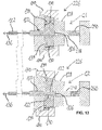
- the impressing according to method step c) can be achieved by means of a device 126, as shown in FIG Fig. 12 in a first embodiment, or by means of a device 226 as shown in FIG FIG. 13 is shown in a second embodiment, take place.
- the FIG. 12 13 shows the device 126 or 226 in a first state C1 before the impressing and a second state C2 during or after the impressing.
- FIG. 12 shows the device 126 in a sectional view in the two states C1 and C2, in the viewing direction above before the impressing and below during or after the stamping.
- the device 126 comprises a closing die 128, which has recesses 130.
- movable in a radial direction 132 Umform stresses 134 are arranged.
- Umform stresses 134 are arranged in the recesses 130.
- these forming bodies 134 are delivered radially inward, locking grooves 124 are formed in the connecting portion 100.
- elongation of the connecting portion 100 in a longitudinal direction 136 is effected.
- the end surface 106 abuts against a punch 138, which before embossing has a distance depending on the elongation of the connecting portion 100 by the embossing to the end surface 106.
- the Umform stresses 134 are delivered radially when the actuators 140 move in the longitudinal direction 136.
- Fig. 13 shows the device 226 as a second embodiment.
- the device 226 is similar to that in FIG Fig. 12 constructed device 126 constructed.
- the same and functionally identical elements are provided with the same reference numerals.
- the device 226 has a punch 238, which is spring-mounted by means of a spring 250 in the longitudinal direction 136.
Landscapes
- Engineering & Computer Science (AREA)
- Mechanical Engineering (AREA)
- Forging (AREA)
- Punching Or Piercing (AREA)
Applications Claiming Priority (1)
| Application Number | Priority Date | Filing Date | Title |
|---|---|---|---|
| DE102013010495.5A DE102013010495A1 (de) | 2013-06-25 | 2013-06-25 | Vefahren und Vorrichtung zur Herstellung eines mit einer Endfläche versehenen Verbindungsabschnitts als Teil eines Werkzeuges |
Publications (2)
| Publication Number | Publication Date |
|---|---|
| EP2839900A1 true EP2839900A1 (fr) | 2015-02-25 |
| EP2839900B1 EP2839900B1 (fr) | 2017-07-12 |
Family
ID=50349531
Family Applications (1)
| Application Number | Title | Priority Date | Filing Date |
|---|---|---|---|
| EP14161805.8A Active EP2839900B1 (fr) | 2013-06-25 | 2014-03-26 | Procédé et dispositif de fabrication d'une section de raccordement pourvue d'une face terminale comme élément d'un outil |
Country Status (3)
| Country | Link |
|---|---|
| EP (1) | EP2839900B1 (fr) |
| CN (1) | CN104249129B (fr) |
| DE (1) | DE102013010495A1 (fr) |
Cited By (3)
| Publication number | Priority date | Publication date | Assignee | Title |
|---|---|---|---|---|
| EP3639947A1 (fr) | 2018-10-19 | 2020-04-22 | Mac Panther GmbH | Procédé et dispositif de fabrication d'un élément de raccordement |
| EP3639946A1 (fr) | 2018-10-19 | 2020-04-22 | Mac Panther GmbH | Élément de raccordement, son procédé et son dispositif de fabrication |
| DE102020007945A1 (de) | 2020-12-24 | 2022-06-30 | Mac Panther Gmbh | Verbindungsabschnitt mit einseitig offener Verriegelungsnut |
Citations (7)
| Publication number | Priority date | Publication date | Assignee | Title |
|---|---|---|---|---|
| DE8433275U1 (de) | 1984-11-14 | 1986-03-27 | Hawera Probst Gmbh + Co, 7980 Ravensburg | Bohrwerkzeug |
| DE3015893C2 (fr) * | 1980-04-24 | 1991-10-02 | Hilti Ag, Schaan, Li | |
| DE19915303A1 (de) | 1998-04-03 | 1999-10-14 | Hawera Probst Gmbh | Bohrwerkzeug und Verfahren zu seiner Herstellung |
| DE19604279B4 (de) * | 1996-02-07 | 2005-04-28 | Bosch Gmbh Robert | Einsatzwerkzeuge für Bohrhämmer und Verfahren zu seiner Herstellung |
| EP2361702A1 (fr) | 2010-02-22 | 2011-08-31 | HILTI Aktiengesellschaft | Procédé de fabrication pour une extrémité enfichable |
| EP2181783B1 (fr) | 2008-11-03 | 2011-10-26 | Südsta AG | Tige cannelée avec rebord d'extrêmité roulé et son procédé de fabrication |
| DE102010018791A1 (de) * | 2010-04-29 | 2011-11-03 | Illinois Tool Works Inc. | Verfahren zur Herstellung eines länglichen Werkzeugs mit einem Arbeitsabschnitt und einem Einsteckabschnitt |
Family Cites Families (7)
| Publication number | Priority date | Publication date | Assignee | Title |
|---|---|---|---|---|
| DE19915305C2 (de) * | 1999-04-03 | 2003-11-20 | Hawera Probst Gmbh | Bohrwerkzeug |
| ATE332780T1 (de) * | 2002-02-28 | 2006-08-15 | Bosch Gmbh Robert | Verfahren zur herstellung eines bohrers oder fräsers |
| JP4879878B2 (ja) * | 2005-01-31 | 2012-02-22 | 昭和電工株式会社 | 据え込み加工方法及び据え込み加工装置 |
| DE102009028020B4 (de) * | 2009-07-27 | 2011-07-28 | Hilti Aktiengesellschaft | Bohrer und Herstellungsverfahren |
| DE102010028474A1 (de) * | 2010-05-03 | 2011-11-03 | Hilti Aktiengesellschaft | Hohlbohrer und Herstellungsverfahren |
| DE102010061905A1 (de) | 2010-11-24 | 2012-05-24 | Mac Panther Gmbh | Verfahren zur Herstellung des Einsteckendes eines Bohrers |
| DE102012204609A1 (de) | 2012-03-22 | 2013-09-26 | Mac Panther Gmbh | Verfahren und Vorrichtung zur Herstellung eines Verbindungsabschnitts als Teil eines Werkzeugs |
-
2013
- 2013-06-25 DE DE102013010495.5A patent/DE102013010495A1/de not_active Withdrawn
-
2014
- 2014-03-26 EP EP14161805.8A patent/EP2839900B1/fr active Active
- 2014-06-25 CN CN201410291375.8A patent/CN104249129B/zh not_active Expired - Fee Related
Patent Citations (7)
| Publication number | Priority date | Publication date | Assignee | Title |
|---|---|---|---|---|
| DE3015893C2 (fr) * | 1980-04-24 | 1991-10-02 | Hilti Ag, Schaan, Li | |
| DE8433275U1 (de) | 1984-11-14 | 1986-03-27 | Hawera Probst Gmbh + Co, 7980 Ravensburg | Bohrwerkzeug |
| DE19604279B4 (de) * | 1996-02-07 | 2005-04-28 | Bosch Gmbh Robert | Einsatzwerkzeuge für Bohrhämmer und Verfahren zu seiner Herstellung |
| DE19915303A1 (de) | 1998-04-03 | 1999-10-14 | Hawera Probst Gmbh | Bohrwerkzeug und Verfahren zu seiner Herstellung |
| EP2181783B1 (fr) | 2008-11-03 | 2011-10-26 | Südsta AG | Tige cannelée avec rebord d'extrêmité roulé et son procédé de fabrication |
| EP2361702A1 (fr) | 2010-02-22 | 2011-08-31 | HILTI Aktiengesellschaft | Procédé de fabrication pour une extrémité enfichable |
| DE102010018791A1 (de) * | 2010-04-29 | 2011-11-03 | Illinois Tool Works Inc. | Verfahren zur Herstellung eines länglichen Werkzeugs mit einem Arbeitsabschnitt und einem Einsteckabschnitt |
Cited By (8)
| Publication number | Priority date | Publication date | Assignee | Title |
|---|---|---|---|---|
| EP3639947A1 (fr) | 2018-10-19 | 2020-04-22 | Mac Panther GmbH | Procédé et dispositif de fabrication d'un élément de raccordement |
| EP3639946A1 (fr) | 2018-10-19 | 2020-04-22 | Mac Panther GmbH | Élément de raccordement, son procédé et son dispositif de fabrication |
| DE102018126086A1 (de) | 2018-10-19 | 2020-04-23 | Mac Panther Gmbh | Verbindungselement, Verfahren und Vorrichtung zu seiner Herstellung |
| DE102018126093A1 (de) | 2018-10-19 | 2020-04-23 | Mac Panther Gmbh | Verfahren und Vorrichtung zur Herstellung eines Verbindungselementes |
| US11027327B2 (en) | 2018-10-19 | 2021-06-08 | Mac Panther Gmbh | Method and apparatus for producing a connecting element |
| US11565306B2 (en) | 2018-10-19 | 2023-01-31 | Mac Panther Gmbh | Connecting element, method and apparatus for its production |
| DE102018126086B4 (de) | 2018-10-19 | 2023-10-12 | Mac Panther Gmbh | Verbindungselement, Verfahren und Vorrichtung zu seiner Herstellung |
| DE102020007945A1 (de) | 2020-12-24 | 2022-06-30 | Mac Panther Gmbh | Verbindungsabschnitt mit einseitig offener Verriegelungsnut |
Also Published As
| Publication number | Publication date |
|---|---|
| CN104249129B (zh) | 2018-07-20 |
| EP2839900B1 (fr) | 2017-07-12 |
| DE102013010495A1 (de) | 2015-01-08 |
| CN104249129A (zh) | 2014-12-31 |
Similar Documents
| Publication | Publication Date | Title |
|---|---|---|
| EP2641673B1 (fr) | Procédé et dispositif de fabrication d'une section de raccordement comme élément d'un outil | |
| EP2440341B1 (fr) | Procédé et dispositif de fabrication de pièces allongées en métal pourvues de rainures hélicoïdales, en particulier des forets hélicoïdaux ou des vis sans fin | |
| EP2484462B1 (fr) | Procédé de production d'une préforme forgée et dispositif de déformage ou dispositif de refoulment chaud | |
| EP2458131B1 (fr) | Procédé pour la fabrication de l'extrémité enfichable d'un foret | |
| EP2839900B1 (fr) | Procédé et dispositif de fabrication d'une section de raccordement pourvue d'une face terminale comme élément d'un outil | |
| DE4401674A1 (de) | Verfahren sowie Vorrichtung zum Lochen von Werkstücken | |
| EP1252947B1 (fr) | Procédé de fabrication d'un élément d'essieu pour un véhicule automobile | |
| DE102010011711B4 (de) | Verfahren und Vorrichtung zur spanlosen Herstellung von Verbindungs-, Befestigungs- oder Verschlusselementen aus Metall mit Außengewinde | |
| DE102009052879B4 (de) | Stanz-Prägeniet | |
| DE102008023696A1 (de) | Verfahren zur Herstellung von Hohlwellengrundkörpern sowie nach dem Verfahren hergestellte Hohlwellengrundkörper | |
| DE102007046788B3 (de) | Verfahren zum Herstellen eines Schließringbolzens und Schließringbolzen | |
| DE102010041164B4 (de) | Verfahren zum Herstellen eines Bohrers | |
| EP3639947B1 (fr) | Procédé et dispositif de fabrication d'un élément de raccordement | |
| EP2722116B1 (fr) | Procédé et paire de mâchoires de pincement destinés à la fabrication d'une vis de forage, et vis ou rivet de forage ou foreur | |
| DE102014116786A1 (de) | Verfahren zur Herstellung eines rotationssymmetrischen Formkörpers | |
| DE3614619C1 (de) | Verfahren und Vorrichtung zur Herstellung von Zahnraedern | |
| DE102007005886B4 (de) | Verfahren zur Herstellung eines Nutzfahrzeug-Achsschenkels | |
| DE102018126086A1 (de) | Verbindungselement, Verfahren und Vorrichtung zu seiner Herstellung | |
| DE102019002187B4 (de) | Verfahren und Vorrichtung zum Herstellen eines Bauteils mit Gewinde | |
| DE102018217822B3 (de) | Verfahren zur Herstellung mindestens einer Verzahnung an einem Bauteil und Werkzeug zur Durchführung des Verfahrens | |
| DE102008054687A1 (de) | Verfahren zur Herstellung einer Zahnstange für ein Lenkgetriebe | |
| DE10344706B4 (de) | Verfahren zum Trennen eines Hohlprofils | |
| DE926337C (de) | Verfahren und Vorrichtung zum Herstellen von Boizen mit angestauchtem Kopf, insbesondere Schraubenbolzen | |
| DE946941C (de) | Verfahren zum Herstellen eines Vielkant-, insbesondere Sechskantkopfes an einem zylindrischen Ausgangswerkstueck | |
| WO2012024805A1 (fr) | Procédé de formage d'un tronçon d'extrémité passant d'un matériau en barre |
Legal Events
| Date | Code | Title | Description |
|---|---|---|---|
| PUAI | Public reference made under article 153(3) epc to a published international application that has entered the european phase |
Free format text: ORIGINAL CODE: 0009012 |
|
| 17P | Request for examination filed |
Effective date: 20140326 |
|
| AK | Designated contracting states |
Kind code of ref document: A1 Designated state(s): AL AT BE BG CH CY CZ DE DK EE ES FI FR GB GR HR HU IE IS IT LI LT LU LV MC MK MT NL NO PL PT RO RS SE SI SK SM TR |
|
| AX | Request for extension of the european patent |
Extension state: BA ME |
|
| R17P | Request for examination filed (corrected) |
Effective date: 20150825 |
|
| RBV | Designated contracting states (corrected) |
Designated state(s): AL AT BE BG CH CY CZ DE DK EE ES FI FR GB GR HR HU IE IS IT LI LT LU LV MC MK MT NL NO PL PT RO RS SE SI SK SM TR |
|
| 17Q | First examination report despatched |
Effective date: 20160210 |
|
| GRAP | Despatch of communication of intention to grant a patent |
Free format text: ORIGINAL CODE: EPIDOSNIGR1 |
|
| RIC1 | Information provided on ipc code assigned before grant |
Ipc: B23B 31/00 20060101ALI20170126BHEP Ipc: B21J 5/12 20060101ALN20170126BHEP Ipc: B21K 5/10 20060101AFI20170126BHEP |
|
| INTG | Intention to grant announced |
Effective date: 20170209 |
|
| GRAS | Grant fee paid |
Free format text: ORIGINAL CODE: EPIDOSNIGR3 |
|
| GRAA | (expected) grant |
Free format text: ORIGINAL CODE: 0009210 |
|
| AK | Designated contracting states |
Kind code of ref document: B1 Designated state(s): AL AT BE BG CH CY CZ DE DK EE ES FI FR GB GR HR HU IE IS IT LI LT LU LV MC MK MT NL NO PL PT RO RS SE SI SK SM TR |
|
| REG | Reference to a national code |
Ref country code: GB Ref legal event code: FG4D Free format text: NOT ENGLISH |
|
| REG | Reference to a national code |
Ref country code: CH Ref legal event code: EP Ref country code: CH Ref legal event code: NV Representative=s name: NOVAGRAAF INTERNATIONAL SA, CH |
|
| REG | Reference to a national code |
Ref country code: AT Ref legal event code: REF Ref document number: 907857 Country of ref document: AT Kind code of ref document: T Effective date: 20170715 |
|
| REG | Reference to a national code |
Ref country code: IE Ref legal event code: FG4D Free format text: LANGUAGE OF EP DOCUMENT: GERMAN |
|
| REG | Reference to a national code |
Ref country code: DE Ref legal event code: R096 Ref document number: 502014004521 Country of ref document: DE |
|
| REG | Reference to a national code |
Ref country code: NL Ref legal event code: MP Effective date: 20170712 |
|
| REG | Reference to a national code |
Ref country code: LT Ref legal event code: MG4D |
|
| PG25 | Lapsed in a contracting state [announced via postgrant information from national office to epo] |
Ref country code: SE Free format text: LAPSE BECAUSE OF FAILURE TO SUBMIT A TRANSLATION OF THE DESCRIPTION OR TO PAY THE FEE WITHIN THE PRESCRIBED TIME-LIMIT Effective date: 20170712 Ref country code: FI Free format text: LAPSE BECAUSE OF FAILURE TO SUBMIT A TRANSLATION OF THE DESCRIPTION OR TO PAY THE FEE WITHIN THE PRESCRIBED TIME-LIMIT Effective date: 20170712 Ref country code: LT Free format text: LAPSE BECAUSE OF FAILURE TO SUBMIT A TRANSLATION OF THE DESCRIPTION OR TO PAY THE FEE WITHIN THE PRESCRIBED TIME-LIMIT Effective date: 20170712 Ref country code: HR Free format text: LAPSE BECAUSE OF FAILURE TO SUBMIT A TRANSLATION OF THE DESCRIPTION OR TO PAY THE FEE WITHIN THE PRESCRIBED TIME-LIMIT Effective date: 20170712 Ref country code: NL Free format text: LAPSE BECAUSE OF FAILURE TO SUBMIT A TRANSLATION OF THE DESCRIPTION OR TO PAY THE FEE WITHIN THE PRESCRIBED TIME-LIMIT Effective date: 20170712 Ref country code: NO Free format text: LAPSE BECAUSE OF FAILURE TO SUBMIT A TRANSLATION OF THE DESCRIPTION OR TO PAY THE FEE WITHIN THE PRESCRIBED TIME-LIMIT Effective date: 20171012 |
|
| PG25 | Lapsed in a contracting state [announced via postgrant information from national office to epo] |
Ref country code: ES Free format text: LAPSE BECAUSE OF FAILURE TO SUBMIT A TRANSLATION OF THE DESCRIPTION OR TO PAY THE FEE WITHIN THE PRESCRIBED TIME-LIMIT Effective date: 20170712 Ref country code: PL Free format text: LAPSE BECAUSE OF FAILURE TO SUBMIT A TRANSLATION OF THE DESCRIPTION OR TO PAY THE FEE WITHIN THE PRESCRIBED TIME-LIMIT Effective date: 20170712 Ref country code: IS Free format text: LAPSE BECAUSE OF FAILURE TO SUBMIT A TRANSLATION OF THE DESCRIPTION OR TO PAY THE FEE WITHIN THE PRESCRIBED TIME-LIMIT Effective date: 20171112 Ref country code: GR Free format text: LAPSE BECAUSE OF FAILURE TO SUBMIT A TRANSLATION OF THE DESCRIPTION OR TO PAY THE FEE WITHIN THE PRESCRIBED TIME-LIMIT Effective date: 20171013 Ref country code: RS Free format text: LAPSE BECAUSE OF FAILURE TO SUBMIT A TRANSLATION OF THE DESCRIPTION OR TO PAY THE FEE WITHIN THE PRESCRIBED TIME-LIMIT Effective date: 20170712 Ref country code: BG Free format text: LAPSE BECAUSE OF FAILURE TO SUBMIT A TRANSLATION OF THE DESCRIPTION OR TO PAY THE FEE WITHIN THE PRESCRIBED TIME-LIMIT Effective date: 20171012 Ref country code: LV Free format text: LAPSE BECAUSE OF FAILURE TO SUBMIT A TRANSLATION OF THE DESCRIPTION OR TO PAY THE FEE WITHIN THE PRESCRIBED TIME-LIMIT Effective date: 20170712 |
|
| REG | Reference to a national code |
Ref country code: FR Ref legal event code: PLFP Year of fee payment: 5 |
|
| REG | Reference to a national code |
Ref country code: DE Ref legal event code: R097 Ref document number: 502014004521 Country of ref document: DE |
|
| PG25 | Lapsed in a contracting state [announced via postgrant information from national office to epo] |
Ref country code: RO Free format text: LAPSE BECAUSE OF FAILURE TO SUBMIT A TRANSLATION OF THE DESCRIPTION OR TO PAY THE FEE WITHIN THE PRESCRIBED TIME-LIMIT Effective date: 20170712 Ref country code: DK Free format text: LAPSE BECAUSE OF FAILURE TO SUBMIT A TRANSLATION OF THE DESCRIPTION OR TO PAY THE FEE WITHIN THE PRESCRIBED TIME-LIMIT Effective date: 20170712 Ref country code: CZ Free format text: LAPSE BECAUSE OF FAILURE TO SUBMIT A TRANSLATION OF THE DESCRIPTION OR TO PAY THE FEE WITHIN THE PRESCRIBED TIME-LIMIT Effective date: 20170712 |
|
| PLBE | No opposition filed within time limit |
Free format text: ORIGINAL CODE: 0009261 |
|
| STAA | Information on the status of an ep patent application or granted ep patent |
Free format text: STATUS: NO OPPOSITION FILED WITHIN TIME LIMIT |
|
| PG25 | Lapsed in a contracting state [announced via postgrant information from national office to epo] |
Ref country code: SM Free format text: LAPSE BECAUSE OF FAILURE TO SUBMIT A TRANSLATION OF THE DESCRIPTION OR TO PAY THE FEE WITHIN THE PRESCRIBED TIME-LIMIT Effective date: 20170712 Ref country code: EE Free format text: LAPSE BECAUSE OF FAILURE TO SUBMIT A TRANSLATION OF THE DESCRIPTION OR TO PAY THE FEE WITHIN THE PRESCRIBED TIME-LIMIT Effective date: 20170712 Ref country code: IT Free format text: LAPSE BECAUSE OF FAILURE TO SUBMIT A TRANSLATION OF THE DESCRIPTION OR TO PAY THE FEE WITHIN THE PRESCRIBED TIME-LIMIT Effective date: 20170712 Ref country code: SK Free format text: LAPSE BECAUSE OF FAILURE TO SUBMIT A TRANSLATION OF THE DESCRIPTION OR TO PAY THE FEE WITHIN THE PRESCRIBED TIME-LIMIT Effective date: 20170712 |
|
| 26N | No opposition filed |
Effective date: 20180413 |
|
| PG25 | Lapsed in a contracting state [announced via postgrant information from national office to epo] |
Ref country code: SI Free format text: LAPSE BECAUSE OF FAILURE TO SUBMIT A TRANSLATION OF THE DESCRIPTION OR TO PAY THE FEE WITHIN THE PRESCRIBED TIME-LIMIT Effective date: 20170712 |
|
| PG25 | Lapsed in a contracting state [announced via postgrant information from national office to epo] |
Ref country code: MT Free format text: LAPSE BECAUSE OF FAILURE TO SUBMIT A TRANSLATION OF THE DESCRIPTION OR TO PAY THE FEE WITHIN THE PRESCRIBED TIME-LIMIT Effective date: 20170712 |
|
| GBPC | Gb: european patent ceased through non-payment of renewal fee |
Effective date: 20180326 |
|
| PG25 | Lapsed in a contracting state [announced via postgrant information from national office to epo] |
Ref country code: MC Free format text: LAPSE BECAUSE OF FAILURE TO SUBMIT A TRANSLATION OF THE DESCRIPTION OR TO PAY THE FEE WITHIN THE PRESCRIBED TIME-LIMIT Effective date: 20170712 |
|
| REG | Reference to a national code |
Ref country code: BE Ref legal event code: MM Effective date: 20180331 |
|
| REG | Reference to a national code |
Ref country code: IE Ref legal event code: MM4A |
|
| PG25 | Lapsed in a contracting state [announced via postgrant information from national office to epo] |
Ref country code: LU Free format text: LAPSE BECAUSE OF NON-PAYMENT OF DUE FEES Effective date: 20180326 |
|
| PG25 | Lapsed in a contracting state [announced via postgrant information from national office to epo] |
Ref country code: IE Free format text: LAPSE BECAUSE OF NON-PAYMENT OF DUE FEES Effective date: 20180326 |
|
| PG25 | Lapsed in a contracting state [announced via postgrant information from national office to epo] |
Ref country code: GB Free format text: LAPSE BECAUSE OF NON-PAYMENT OF DUE FEES Effective date: 20180326 Ref country code: BE Free format text: LAPSE BECAUSE OF NON-PAYMENT OF DUE FEES Effective date: 20180331 |
|
| PGFP | Annual fee paid to national office [announced via postgrant information from national office to epo] |
Ref country code: FR Payment date: 20190326 Year of fee payment: 6 |
|
| PGFP | Annual fee paid to national office [announced via postgrant information from national office to epo] |
Ref country code: AT Payment date: 20190319 Year of fee payment: 6 |
|
| PG25 | Lapsed in a contracting state [announced via postgrant information from national office to epo] |
Ref country code: TR Free format text: LAPSE BECAUSE OF FAILURE TO SUBMIT A TRANSLATION OF THE DESCRIPTION OR TO PAY THE FEE WITHIN THE PRESCRIBED TIME-LIMIT Effective date: 20170712 |
|
| PG25 | Lapsed in a contracting state [announced via postgrant information from national office to epo] |
Ref country code: PT Free format text: LAPSE BECAUSE OF FAILURE TO SUBMIT A TRANSLATION OF THE DESCRIPTION OR TO PAY THE FEE WITHIN THE PRESCRIBED TIME-LIMIT Effective date: 20170712 |
|
| PGFP | Annual fee paid to national office [announced via postgrant information from national office to epo] |
Ref country code: CH Payment date: 20200325 Year of fee payment: 7 |
|
| PG25 | Lapsed in a contracting state [announced via postgrant information from national office to epo] |
Ref country code: CY Free format text: LAPSE BECAUSE OF FAILURE TO SUBMIT A TRANSLATION OF THE DESCRIPTION OR TO PAY THE FEE WITHIN THE PRESCRIBED TIME-LIMIT Effective date: 20170712 Ref country code: MK Free format text: LAPSE BECAUSE OF NON-PAYMENT OF DUE FEES Effective date: 20170712 Ref country code: HU Free format text: LAPSE BECAUSE OF FAILURE TO SUBMIT A TRANSLATION OF THE DESCRIPTION OR TO PAY THE FEE WITHIN THE PRESCRIBED TIME-LIMIT; INVALID AB INITIO Effective date: 20140326 |
|
| PG25 | Lapsed in a contracting state [announced via postgrant information from national office to epo] |
Ref country code: AL Free format text: LAPSE BECAUSE OF FAILURE TO SUBMIT A TRANSLATION OF THE DESCRIPTION OR TO PAY THE FEE WITHIN THE PRESCRIBED TIME-LIMIT Effective date: 20170712 |
|
| REG | Reference to a national code |
Ref country code: AT Ref legal event code: MM01 Ref document number: 907857 Country of ref document: AT Kind code of ref document: T Effective date: 20200326 |
|
| PG25 | Lapsed in a contracting state [announced via postgrant information from national office to epo] |
Ref country code: FR Free format text: LAPSE BECAUSE OF NON-PAYMENT OF DUE FEES Effective date: 20200331 Ref country code: AT Free format text: LAPSE BECAUSE OF NON-PAYMENT OF DUE FEES Effective date: 20200326 |
|
| REG | Reference to a national code |
Ref country code: CH Ref legal event code: PL |
|
| PG25 | Lapsed in a contracting state [announced via postgrant information from national office to epo] |
Ref country code: LI Free format text: LAPSE BECAUSE OF NON-PAYMENT OF DUE FEES Effective date: 20210331 Ref country code: CH Free format text: LAPSE BECAUSE OF NON-PAYMENT OF DUE FEES Effective date: 20210331 |
|
| PGFP | Annual fee paid to national office [announced via postgrant information from national office to epo] |
Ref country code: DE Payment date: 20240412 Year of fee payment: 11 |