EP2837527A1 - Blockierbarer Klappsitz - Google Patents
Blockierbarer Klappsitz Download PDFInfo
- Publication number
- EP2837527A1 EP2837527A1 EP13180366.0A EP13180366A EP2837527A1 EP 2837527 A1 EP2837527 A1 EP 2837527A1 EP 13180366 A EP13180366 A EP 13180366A EP 2837527 A1 EP2837527 A1 EP 2837527A1
- Authority
- EP
- European Patent Office
- Prior art keywords
- seat
- locking
- locking element
- seat surface
- passenger seat
- Prior art date
- Legal status (The legal status is an assumption and is not a legal conclusion. Google has not performed a legal analysis and makes no representation as to the accuracy of the status listed.)
- Granted
Links
- 230000000903 blocking effect Effects 0.000 claims description 29
- 230000001960 triggered effect Effects 0.000 description 2
- 238000010276 construction Methods 0.000 description 1
- 238000009434 installation Methods 0.000 description 1
Images

Classifications
-
- B—PERFORMING OPERATIONS; TRANSPORTING
- B60—VEHICLES IN GENERAL
- B60N—SEATS SPECIALLY ADAPTED FOR VEHICLES; VEHICLE PASSENGER ACCOMMODATION NOT OTHERWISE PROVIDED FOR
- B60N2/00—Seats specially adapted for vehicles; Arrangement or mounting of seats in vehicles
- B60N2/24—Seats specially adapted for vehicles; Arrangement or mounting of seats in vehicles for particular purposes or particular vehicles
- B60N2/242—Bus seats
-
- B—PERFORMING OPERATIONS; TRANSPORTING
- B60—VEHICLES IN GENERAL
- B60N—SEATS SPECIALLY ADAPTED FOR VEHICLES; VEHICLE PASSENGER ACCOMMODATION NOT OTHERWISE PROVIDED FOR
- B60N2/00—Seats specially adapted for vehicles; Arrangement or mounting of seats in vehicles
- B60N2/24—Seats specially adapted for vehicles; Arrangement or mounting of seats in vehicles for particular purposes or particular vehicles
- B60N2/30—Non-dismountable or dismountable seats storable in a non-use position, e.g. foldable spare seats
- B60N2/3038—Cushion movements
- B60N2/304—Cushion movements by rotation only
- B60N2/3045—Cushion movements by rotation only about transversal axis
- B60N2/305—Cushion movements by rotation only about transversal axis the cushion being hinged on the vehicle frame
Definitions
- the invention relates to a passenger seat with a backrest and a seat according to the closer defined in the preamble of claim 1.
- the present invention controllable from a remote from the passenger seat position locking device with which the seat can be locked in its vertical rest position, it is for example a driver of a bus possible from his driver's seat certain or possibly also to lock all passenger seats that are located in the bus, so that a use of these passenger seats is no longer possible.
- the solution according to the invention considerably simplifies the locking of the seat surface of the passenger seat in its vertical rest position and thereby offers the possibility of blocking certain passenger seats for use in order to create more space in the interior of the vehicle and thereby ultimately be able to accommodate more passengers.
- the electrical actuating device is designed as an electromagnet. Through the use of an electromagnet for moving the locking element is given a very reliable in practice execution of the electrical actuator.
- the locking element is retractable into an opening of a component which is at least indirectly connected to the seat surface, resulting in a construction with little effort for the locking of the seat surface.
- the seat can still be tilted in its vertical rest position in which it is locked by means of the locking device, nevertheless, by a certain amount, for example, one between the seat and To be able to remove the object clamped backrest by slightly tilting the seat in the direction of its horizontal use position. Furthermore, it is ensured in this way that even in the case in which there is an object between the seat surface and the backrest and the seat surface can not completely assume its vertical rest position, a locking of the seat surface takes place. From the above-explained locking of the seat in its vertical rest position is therefore also includes a state in which the seat can be tilted starting from its vertical rest position by a certain, determined by the length of the slot angle in the direction of its horizontal use position.
- a blocking element can be provided which is arranged in the use position of the seat surface relative to the locking element in such a way that it blocks the movement of the locking element.
- the blocking element prevents the locking element from moving into its end position, so that when the seat surface is in its horizontal use position, the movement of the locking element is blocked. In this way, the locking element is prevented from moving into its end position when the component connected to the seat surface is not yet in the position in which the opening is located in the same in front of the locking element.
- the blocking element In order to hold the blocking element reliably and by simple means in its blocking position the blocking element, may further be provided that the blocking element is held by a spring element in its blocking the movement of the locking element position.
- Another very advantageous embodiment of the invention may consist in that the component connected to the seat surface is arranged opposite to the blocking element, that the blocking element is moved by the movement of the component connected to the seat in a position releasing the movement of the locking element.
- the locking element no longer blocks the locking element as soon as the opening of the component connected to the seat is in front of the locking element, whereby despite the above-described blocking of the locking element in the horizontal position of the seat a secure locking the same in their vertical position is given.
- It is a forced control of the blocking element which can be dispensed with a complex electronic control of the same.
- a very simple to implement in practice embodiment of this forced control of the locking element by means of the seat connected to the component arises when a driver for moving the locking element is mounted in its the movement of the locking element releasing position on the component connected to the seat.
- a display device for indicating the locked position of the seat surface can furthermore be provided.
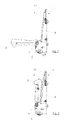
- Fig. 1 shows a side view of a designed as a lockable folding seat passenger seat 1, which has a backrest 2 and a seat 3 in a conventional manner.
- the backrest 2 is rigidly attached to a seat frame 4.
- the seat 3 is between a in Fig. 1 shown use position in which the seat surface 3 is oriented substantially horizontally, and a in Fig. 2 illustrated rest position in which the seat surface 3 is oriented substantially vertically, about a mounted on the seat frame 4 axis of rotation 5 hinged.
- the seat 3 is designed in the present case, that after the passenger leaves the passenger seat 1, it automatically goes from the horizontal use position to the vertical rest position.
- suitable spring elements may be provided, which may be embodied in a manner known per se, for example as torsion springs.
- the passenger seat 1 is for installation in a means of transport, such as a bus, in particular a city bus, provided, wherein the in Fig. 2 shown rest position of the seat 3 serves to increase the usable area within the means of transport to accommodate more passengers can.
- a means of transport such as a bus, in particular a city bus, provided, wherein the in Fig. 2 shown rest position of the seat 3 serves to increase the usable area within the means of transport to accommodate more passengers can.
- a locking device 6 is provided, which in the Figures 1 and 2 only hinted at.
- the locking device 6 is controllable from a position remote from the passenger seat 1, in particular from a driver's seat, not shown, of the means of transport in which a plurality of the passenger seats 1 are located.
- This control of the locking device 6 can in the FIGS. 3 to 6 represented locking element 7 of the locking device 6 are brought into a seat 3, the locking position in its rest position.
- the connection of a control device, not shown, to which the driver of the means of transport has access, with the locking device 6 may be wireless or wired.
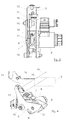
- Fig. 3 shows a more detailed view of the locking device 6 in its the seat 3 in its rest position locking position.
- the locking device 6 has an electrical actuating device 8, which serves to move the locking element 7 between the seat 3 releasing and the seat surface 3 in its rest position locking position.
- the direction of movement of the locking element 7 denoted by "x" runs parallel to the axis of rotation 5 of the seat surface 3.
- the electrical actuating device 8, which in the present case is designed as an electromagnet, is attached to a frame element 9 which receives or engages further parts of the locking device 6 the other components of the locking device 6 are mounted.
- the electrical actuator 8 of the locking device 6 is thus connected to a rigid part of the passenger seat 1.
- the locking device 6 has a component 10 which is at least indirectly connected to the seat surface 3 and which is in the FIGS. 4 to 6 is more clearly recognizable and its movement due to the connection with the seat surface 3 is coupled to the movement of the seat surface 3.
- the connection of the component 10 with the seat surface 3 takes place in the present case via a in the FIGS. 4 to 6 illustrated, a part of the seat frame 4 performing frame tube 4a.
- the component 10 has an opening 11, which is formed in the present case as a slot and in which the locking element 7 retracts to lock the seat 3 in its rest position. In Fig. 3 the opening 11 in the component 10 is not recognizable, but merely indicated by the reference numeral 11.
- Fig. 4 shows the indicated only by dashed lines seat 3 in its use position in which both the seat surface 3 and the component 10 are aligned substantially horizontally, wherein the component 10 relative to the seat surface 3, however, is offset by 180 °.
- Fig. 5 the seat 3 in its rest position, in which both the seat surface 3 and the component 10 are aligned substantially vertically. While the seat 3 is directed upward, the component 10 is directed downward and is in a position in which the opening 11 is located in front of the locking element 7, so that the locking element 7 retracts when opening in the opening 11 and the component 10 and thus ultimately locked the seat 3.
- the electric actuator 8 In order to lock the seat 3 in its vertical rest position, so the electric actuator 8 must be actuated to retract the locking member 7 in the opening 11 of the seat 3 connected to the component 10. Since the opening 11, as described above, is formed as a slot, in this position, the seat 3 can again be pivoted slightly forward until the locking member 7 abuts the opposite end of the opening 11 and thus limits the movement of the seat surface 3. As a result, may be between the seat 3 and the backrest 2 trapped objects, such as jackets and the like, easily be removed. Furthermore, an excessive clamping of these objects during the pivoting of the seat 3 is prevented in this way upwards.
- a blocking element 12 is provided whose function with reference to the FIGS. 4 and 5 will be described in more detail below.
- Fig. 4 illustrated blocking the locking element 12 in the use position of the seat 3, the movement of the locking element 7, in which the locking element 12 is disposed in this position in front of the locking element 7 and thus prevents the same to the complete extension.
- a spring element 13 designed as a tension spring in the present case is attached to the same. The spring element 13 thus holds the blocking element 12 in its blocking the movement of the locking element 7 position.
- this has a recess 14 which in the state of Fig. 4 is not aligned with the locking element 7 in order to achieve the blocking of the movement of the locking element 7 described above.
- the component 10 connected to the seat surface 3 when caused by the movement of the seat surface 3, ensures that the locking element 12 is rotated against the force applied by the spring element 13 according to the arrow A about an axis of rotation 15 and thus into motion of the locking element 7 releasing position is moved, which in Fig. 5 is shown.
- a driver 16 which abuts in a certain position during the rotational movement of the component 10 on the locking element 12 and this, as mentioned above, entrains and against the force of the spring element 13 in the position of Fig. 5 brings.
- the driver 16 is formed in the present case as a bolt which is bolted to the component 10. In this position, both the recess 14 in the locking element 12 and the opening 11 in the component 10 are aligned with the direction of movement of the locking element 7, so that this can drive through both the recess 14 and through the opening 11, thereby the component 10 in the in Fig. 5 locked position to lock.
- In the frame member 9 is also a bore, not shown in the figures, in which the locking element 7 retracts in its end position, so that a very high stability of the locking element 7 is achieved in its locking position.
- a slight pivoting of the seat 3 for example, by an angle of about 15 ° possible.
- this position is referred to as the locked position of the seat 3 in its vertical rest position.
- the opening 11 in the component 10 could also be designed as a circular bore if the possibility of moving the seat 3 in its actually locked state would be dispensed with.
- the blocking element 12 makes it possible for a locking device 6 to actuate the position, for example the driver of the means of transport with which the passenger seat 1 is equipped, to actuate the locking device 6 even when the seat surface 3 is still in the horizontal use position.
- the locking element 7 abuts on the blocking element 12 and can its in Fig. 3 Do not reach the end position shown. This is possible only when the blocking element 12 is brought by the movement of the component 10 or by the movement of the seat surface 3 in a position in which the recess 14 in the locking element 12 is aligned with the direction of movement of the locking element 7.
- the locking element 7 only extend when the seat 3 is in its vertical rest position.
- sensors could be provided to interrogate the position of the seat surface 3 or of the component 10 connected to the seat surface 3 and pass it on to a corresponding control device controlling the extension of the locking element 7.
- the passenger seat 1 furthermore has a display element 17 which is attached to the backrest 2 in the exemplary embodiment shown and which serves to indicate the locked position of the seat surface 3.
- the display device 17 is formed as a lighting element, but it would also be possible to additionally or alternatively provide an acoustic display element.
- the display device 17 can be triggered when the locking device 6 has been triggered, but it is also possible to trigger the display device 17 only when the seat surface 3 is in its vertical rest position and was locked there by means of the locking device 6.
Landscapes
- Engineering & Computer Science (AREA)
- Aviation & Aerospace Engineering (AREA)
- Transportation (AREA)
- Mechanical Engineering (AREA)
- Seats For Vehicles (AREA)
Abstract
Description
- Die Erfindung betrifft einen Fahrgastsitz mit einer Rückenlehne und einer Sitzfläche nach der im Oberbegriff von Anspruch 1 näher definierten Art.
- Gattungsgemäße Fahrgastsitze sind aus dem allgemeinen Stand der Technik bekannt. Meist werden die zum Verriegeln der Sitzfläche dieser Fahrgastsitze dienenden Verriegelungseinrichtungen manuell bedient, um eine Nutzung des entsprechenden Fahrgastsitzes zu verhindern, da auf diese Weise zum Beispiel in öffentlichen Verkehrsmitteln eine größere Anzahl an Fahrgästen aufgenommen werden kann. Bei großen Bussen stellt diese manuelle Verriegelung der Sitzfläche in ihrer vertikalen Ruhestellung, in der die Sitzfläche nach oben geklappt ist, einen sehr großen Aufwand dar, der unter anderem aufgrund der Notwendigkeit, den Fahrplan einzuhalten, vom Fahrer eines Busses nicht erbracht werden kann.
- Es ist daher Aufgabe der vorliegenden Erfindung, einen Fahrgastsitz mit einer Rückenlehne und einer gegenüber der Rückenlehne klappbaren Sitzfläche zu schaffen, der eine einfachere Verriegelung der Sitzfläche in ihrer vertikalen Ruhestellung aufweist.
- Erfindungsgemäß wird diese Aufgabe durch die in Anspruch 1 genannten Merkmale gelöst.
- Durch die erfindungsgemäß von einer von dem Fahrgastsitz entfernten Position steuerbare Verriegelungseinrichtung, mit welcher die Sitzfläche in ihrer vertikalen Ruhestellung verriegelt werden kann, ist es beispielsweise einem Fahrer eines Busses möglich, von seinem Fahrersitz aus bestimmte oder gegebenenfalls auch sämtliche Fahrgastsitze, die sich in dem Bus befinden, zu verriegeln, so dass eine Nutzung dieser Fahrgastsitze nicht mehr möglich ist.
- Dabei ist eine Verriegelung der Sitzfläche in ihrer Ruhestellung mittels des Verriegelungselements nur dann möglich, wenn sich die Sitzfläche bereits in ihrer Ruhestellung befindet. Sollte sich die Sitzfläche dagegen in ihrer horizontalen Nutzstellung befinden, was insbesondere dann der Fall ist, wenn sich ein Fahrgast auf dem jeweiligen Fahrgastsitz befindet, so wird die Sitzfläche nicht automatisch in ihre vertikale Ruhestellung gebracht. Vielmehr findet die Verriegelung der Sitzfläche in ihrer vertikalen Ruhestellung in einem solchen Fall erst dann statt, wenn der Fahrgast den jeweiligen Sitz verlässt und die Sitzfläche sich dann selbsttätig von ihrer horizontalen Nutzstellung in ihre vertikale Ruhestellung bewegt.
- Die erfindungsgemäße Lösung vereinfacht die Verriegelung der Sitzfläche des Fahrgastsitzes in ihrer vertikalen Ruhestellung erheblich und bietet dadurch die Möglichkeit, bestimmte Fahrgastsitze für eine Nutzung zu sperren, um auf diese Weise mehr Platz im Innenraum des Verkehrsmittels zu schaffen und dadurch letztendlich mehr Fahrgäste aufnehmen zu können.
- Eine gleichermaßen einfache und zuverlässige Ansteuerung des Verriegelungselements ergibt sich, wenn in einer sehr vorteilhaften Weiterbildung der Erfindung das Verriegelungselement mittels einer elektrischen Betätigungseinrichtung in seine die Sitzfläche in ihrer Ruhestellung verriegelnde Position beweglich ist.
- Dabei kann vorgesehen sein, dass die elektrische Betätigungseinrichtung als Elektromagnet ausgebildet ist. Durch die Verwendung eines Elektromagneten zur Bewegung des Verriegelungselements ist eine in der Praxis sehr zuverlässige Ausführung der elektrischen Betätigungseinrichtung gegeben.
- Des Weiteren kann vorgesehen sein, dass das Verriegelungselement in eine Öffnung eines mit der Sitzfläche zumindest mittelbar verbundenen Bauteils einfahrbar ist, wodurch sich eine mit geringem Aufwand zu realisierende Konstruktion für die Verriegelung der Sitzfläche ergibt.
- Wenn dabei die in dem mit der Sitzfläche verbundenen Bauteil vorgesehene Öffnung als Langloch ausgebildet ist, so kann die Sitzfläche in ihrer vertikalen Ruhestellung, in der sie mittels der Verriegelungseinrichtung verriegelt wird, dennoch um einen gewissen Betrag gekippt werden, beispielsweise um einen zwischen der Sitzfläche und der Rückenlehne eingeklemmten Gegenstand durch leichtes Neigen der Sitzfläche in Richtung ihrer horizontalen Nutzstellung entfernen zu können. Des Weiteren ist auf diese Weise sichergestellt, dass auch in dem Fall, in dem sich zwischen der Sitzfläche und der Rückenlehne ein Gegenstand befindet und die Sitzfläche dadurch ihre vertikale Ruhestellung nicht vollständig einnehmen kann, eine Verriegelung der Sitzfläche stattfindet. Von der oben erläuterten Verriegelung der Sitzfläche in ihrer vertikalen Ruhestellung ist demnach auch ein Zustand umfasst, in dem die Sitzfläche ausgehend von ihrer vertikalen Ruhestellung um einen bestimmten, durch die Länge des Langlochs festgelegten Winkel in Richtung ihrer horizontalen Nutzstellung gekippt werden kann.
- Des Weiteren kann in einer vorteilhaften Weiterbildung der Erfindung ein Sperrelement vorgesehen sein, das in der Nutzstellung der Sitzfläche so gegenüber dem Verriegelungselement angeordnet ist, dass es die Bewegung des Verriegelungselements blockiert. Durch das Sperrelement wird das Verriegelungselement daran gehindert, sich in seine Endstellung zu bewegen, so dass, wenn sich die Sitzfläche in ihrer horizontalen Nutzstellung befindet, die Bewegung des Verriegelungselements blockiert wird. Auf diese Weise wird verhindert, dass das Verriegelungselement sich in seine Endstellung bewegt, wenn das mit der Sitzfläche verbundene Bauteil noch nicht in der Position ist, in der sich die Öffnung in demselben vor dem Verriegelungselement befindet.
- Um das Sperrelement zuverlässig und mit einfachen Mitteln in seiner das Verriegelungselement blockierenden Stellung zu halten, kann des Weiteren vorgesehen sein, dass das Sperrelement durch ein Federelement in seiner die Bewegung des Verriegelungselements blockierenden Stellung gehalten ist.
- Eine weitere sehr vorteilhafte Ausgestaltung der Erfindung kann darin bestehen, dass das mit der Sitzfläche verbundene Bauteil so gegenüber dem Sperrelement angeordnet ist, dass das Sperrelement durch die Bewegung des mit der Sitzfläche verbundenen Bauteils in eine die Bewegung des Verriegelungselements freigebende Stellung bewegt wird. Auf diese Weise wird sichergestellt, dass das Sperrelement das Verriegelungselement nicht mehr blockiert, sobald die Öffnung des mit der Sitzfläche verbundenen Bauteils sich vor dem Verriegelungselement befindet, wodurch trotz der oben beschriebenen Blockierung des Verriegelungselements in der horizontalen Stellung der Sitzfläche ein sicheres Verriegeln derselben in ihrer vertikalen Stellung gegeben ist. Dabei handelt es sich um eine Zwangssteuerung des Sperrelements, wodurch auf eine aufwändige elektronische Steuerung desselben verzichtet werden kann.
- Eine in der Praxis sehr einfach zu realisierende Ausführungsform dieser Zwangssteuerung des Sperrelements mittels des mit der Sitzfläche verbundenen Bauteils ergibt sich, wenn an dem mit der Sitzfläche verbundenen Bauteil ein Mitnehmer zur Bewegung des Sperrelements in seine die Bewegung des Verriegelungselements freigebende Stellung angebracht ist.
- Um den Fahrgästen zu signalisieren, dass der Fahrgastsitz nicht benutzt werden kann, kann des Weiteren eine Anzeigeeinrichtung zur Anzeige der verriegelten Position der Sitzfläche vorgesehen sein.
- Nachfolgend ist ein Ausführungsbeispiel der Erfindung anhand der Zeichnung prinzipmäßig dargestellt.
- Es zeigt:
- Fig. 1
- einen erfindungsgemäßen Fahrgastsitz mit der Sitzfläche in ihrer horizontalen Nutzstellung;
- Fig. 2
- den Fahrgastsitz aus
Fig. 1 mit der Sitzfläche in ihrer vertikalen Ruhestellung; - Fig. 3
- eine Ansicht der Verriegelungseinrichtung des erfindungsgemäßen Fahrgastsitzes gemäß dem Pfeil III aus
Fig. 2 ; - Fig. 4
- eine perspektivische Ansicht der Verriegelungseinrichtung in einer ersten Stellung;
- Fig. 5
- die Verriegelungseinrichtung aus
Fig. 4 in einer zweiten Stellung; und - Fig. 6
- die Verriegelungseinrichtung aus
Fig. 4 in einer dritten Stellung. -
Fig. 1 zeigt eine Seitenansicht eines als blockierbarer Klappsitz ausgebildeten Fahrgastsitzes 1, der in an sich bekannter Weise eine Rückenlehne 2 und eine Sitzfläche 3 aufweist. Die Rückenlehne 2 ist starr an einem Sitzrahmen 4 angebracht. Demgegenüber ist die Sitzfläche 3 zwischen einer inFig. 1 dargestellten Nutzstellung, in dem die Sitzfläche 3 im Wesentlichen horizontal ausgerichtet ist, und einer inFig. 2 dargestellten Ruhestellung, in der die Sitzfläche 3 im Wesentlichen vertikal ausgerichtet ist, um eine an dem Sitzrahmen 4 angebrachte Drehachse 5 klappbar. Die Sitzfläche 3 ist im vorliegenden Fall so ausgelegt, dass sie, nachdem der Fahrgast den Fahrgastsitz 1 verlässt, selbsttätig von der horizontalen Nutzstellung in die vertikale Ruhestellung geht. Hierzu können geeignete Federelemente vorgesehen sein, die in an sich bekannter Weise zum Beispiel als Torsionsfedern ausgeführt sein können. - Der Fahrgastsitz 1 ist zum Einbau in ein Verkehrsmittel, wie beispielsweise einen Bus, insbesondere einen Stadtbus, vorgesehen, wobei die in
Fig. 2 dargestellte Ruhestellung der Sitzfläche 3 dazu dient, die nutzbare Fläche innerhalb des Verkehrsmittels zu vergrößern, um mehr Fahrgäste aufnehmen zu können. - Um die Sitzfläche 3 in ihrer Ruhestellung verriegeln zu können, ist eine Verriegelungseinrichtung 6 vorgesehen, die in den
Figuren 1 und 2 nur angedeutet ist. Die Verriegelungseinrichtung 6 ist von einer von dem Fahrgastsitz 1 entfernten Position, insbesondere von einem nicht dargestellten Fahrersitz des Verkehrsmittels, in dem sich mehrere der Fahrgastsitze 1 befinden, steuerbar. Mittels dieser Steuerung der Verriegelungseinrichtung 6 kann ein in denFiguren 3 bis 6 dargestelltes Verriegelungselement 7 der Verriegelungseinrichtung 6 in eine die Sitzfläche 3 in ihrer Ruhestellung verriegelnde Position gebracht werden. Die Verbindung einer nicht dargestellten Steuereinrichtung, auf die der Fahrer des Verkehrsmittels Zugriff hat, mit der Verriegelungseinrichtung 6 kann kabellos oder kabelgebunden sein. -
Fig. 3 zeigt eine detailliertere Ansicht der Verriegelungseinrichtung 6 in ihrer die Sitzfläche 3 in ihrer Ruhestellung verriegelnden Position. Die Verriegelungseinrichtung 6 weist eine elektrische Betätigungseinrichtung 8 auf, die dazu dient, das Verriegelungselement 7 zwischen der die Sitzfläche 3 freigebenden und die Sitzfläche 3 in ihrer Ruhestellung verriegelnden Position zu bewegen. Die inFig. 3 mit "x" bezeichnete Bewegungsrichtung des Verriegelungselements 7 verläuft parallel zu der Drehachse 5 der Sitzfläche 3. Die elektrische Betätigungseinrichtung 8, die im vorliegenden Fall als Elektromagnet ausgebildet ist, ist an einem Rahmenelement 9 angebracht, das weitere Teile der Verriegelungseinrichtung 6 aufnimmt bzw. an dem weitere Bauteile der Verriegelungseinrichtung 6 gelagert sind. Die elektrische Betätigungseinrichtung 8 der Verriegelungseinrichtung 6 ist also mit einem starren Teil des Fahrgastsitzes 1 verbunden. - Die Verriegelungseinrichtung 6 weist ein mit der Sitzfläche 3 zumindest mittelbar verbundenes Bauteil 10 auf, das in den
Figuren 4 bis 6 deutlicher erkennbar ist und dessen Bewegung aufgrund der Verbindung mit der Sitzfläche 3 an die Bewegung der Sitzfläche 3 gekoppelt ist. Die Verbindung des Bauteils 10 mit der Sitzfläche 3 erfolgt im vorliegenden Fall über ein in denFiguren 4 bis 6 dargestelltes, einen Teil des Sitzrahmens 4 darstellendes Rahmenrohr 4a. Bei der Bewegung der Sitzfläche 3 wird das mit derselben verbundene Bauteil 10 entsprechend bewegt, wie aus einem Vergleich derFiguren 4 bis 6 untereinander erkennbar ist. Das Bauteil 10 weist eine Öffnung 11 auf, die im vorliegenden Fall als Langloch ausgebildet ist und in die das Verriegelungselement 7 zum Verriegeln der Sitzfläche 3 in ihrer Ruhestellung einfährt. InFig. 3 ist die Öffnung 11 in dem Bauteil 10 nicht erkennbar, sondern lediglich mit dem Bezugszeichen 11 angedeutet. -
Fig. 4 zeigt die nur mittels gestrichelter Linien angedeutete Sitzfläche 3 in ihrer Nutzstellung, in der sowohl die Sitzfläche 3 als auch das Bauteil 10 im Wesentlichen horizontal ausgerichtet sind, wobei das Bauteil 10 gegenüber der Sitzfläche 3 jedoch um 180° versetzt ist. Dagegen zeigtFig. 5 die Sitzfläche 3 in ihrer Ruhestellung, in der sowohl die Sitzfläche 3 als auch das Bauteil 10 im Wesentlichen vertikal ausgerichtet sind. Während die Sitzfläche 3 nach oben gerichtet ist, ist das Bauteil 10 nach unten gerichtet und befindet sich in einer Position, in der die Öffnung 11 vor dem Verriegelungselement 7 liegt, sodass das Verriegelungselement 7 beim Ausfahren in die Öffnung 11 einfährt und das Bauteil 10 und somit letztendlich die Sitzfläche 3 verriegelt. - Um die Sitzfläche 3 in ihrer vertikalen Ruhestellung zu verriegeln, muss also die elektrische Betätigungseinrichtung 8 betätigt werden, um das Verriegelungselement 7 in die Öffnung 11 des mit der Sitzfläche 3 verbundenen Bauteils 10 einzufahren. Da die Öffnung 11, wie oben beschrieben, als Langloch ausgebildet ist, kann in dieser Position die Sitzfläche 3 wieder geringfügig nach vorne geschwenkt werden, bis das Verriegelungselement 7 am gegenüberliegenden Ende der Öffnung 11 anschlägt und somit die Bewegung der Sitzfläche 3 begrenzt. Dadurch können eventuell zwischen der Sitzfläche 3 und der Rückenlehne 2 eingeklemmte Gegenstände, wie beispielsweise Jacken und dergleichen, leicht entfernt werden. Des Weiteren wird auf diese Weise ein zu starkes Einklemmen dieser Gegenstände bei der Verschwenkung der Sitzfläche 3 nach oben verhindert.
- Um ein vollständiges Ausfahren des Verriegelungselements 7 in einem Zustand zu verhindern, in dem die Öffnung 11 des Bauteils 10 noch nicht vor dem Verriegelungselement 7 angeordnet ist, ist ein Sperrelement 12 vorgesehen, dessen Funktion unter Bezugnahme auf die
Figuren 4 und5 nachfolgend näher beschrieben wird. Wie inFig. 4 dargestellt, blockiert das Sperrelement 12 in der Nutzstellung der Sitzfläche 3 die Bewegung des Verriegelungselements 7, in dem das Sperrelement 12 in dieser Stellung vor dem Verriegelungselement 7 angeordnet ist und somit das vollständige Ausfahren desselben verhindert. Um das Sperrelement 12 in dieser Position zu halten, ist an demselben ein im vorliegenden Fall als Zugfeder ausgebildetes Federelement 13 angebracht. Das Federelement 13 hält also das Sperrelement 12 in seiner die Bewegung des Verriegelungselements 7 blockierenden Stellung. Um dem Verriegelungselement 7 das Durchfahren durch das Sperrelement 12 zu erlauben, weist dieses eine Ausnehmung 14 auf, die in dem Zustand vonFig. 4 nicht mit dem Verriegelungselement 7 ausgerichtet ist, um die oben beschriebene Blockierung der Bewegung des Verriegelungselements 7 zu erreichen. - Wie aus einem Vergleich der
Figuren 4 und5 hervorgeht, sorgt das mit der Sitzfläche 3 verbundene Bauteil 10 bei seiner durch die Bewegung der Sitzfläche 3 hervorgerufenen Bewegung dafür, dass das Sperrelement 12 entgegen der durch das Federelement 13 aufgebrachten Kraft gemäß dem Pfeil A um eine Drehachse 15 gedreht und damit in eine die Bewegung des Verriegelungselements 7 freigebende Stellung bewegt wird, die inFig. 5 dargestellt ist. Um diese Bewegung des Sperrelements 12 durch die Bewegung des Bauteils 10 hervorzurufen, weist das Bauteil 10 im dargestellten Ausführungsbeispiel einen Mitnehmer 16 auf, der in einer bestimmten Position bei der Drehbewegung des Bauteils 10 an dem Sperrelement 12 anschlägt und dieses, wie oben erwähnt, mitnimmt und gegen die Kraft des Federelements 13 in die Position vonFig. 5 bringt. Der Mitnehmer 16 ist im vorliegenden Fall als Bolzen ausgebildet, der mit dem Bauteil 10 verschraubt ist. In dieser Position sind sowohl die Ausnehmung 14 in dem Sperrelement 12 als auch die Öffnung 11 in dem Bauteil 10 mit der Bewegungsrichtung des Verriegelungselements 7 ausgerichtet, so dass dieses sowohl durch die Ausnehmung 14 als auch durch die Öffnung 11 fahren kann, um dadurch das Bauteil 10 in der inFig. 5 dargestellten Position zu verriegeln. In dem Rahmenelement 9 befindet sich ebenfalls eine in den Figuren nicht dargestellte Bohrung, in welche das Verriegelungselement 7 in seiner Endstellung einfährt, so dass eine sehr hohe Stabilität des Verriegelungselements 7 in seiner Verriegelungsstellung erreicht wird. Wie bereits oben erwähnt, ist aufgrund der Ausführung der Öffnung 11 als Langloch in der verriegelten Position gemäßFig. 5 ein geringfügiges Verschwenken der Sitzfläche 3, beispielsweise um einen Winkel von ca. 15°, möglich. Dennoch wird diese Position als die verriegelte Position der Sitzfläche 3 in ihrer vertikalen Ruhestellung bezeichnet. Gegebenenfalls könnte die Öffnung 11 in dem Bauteil 10 auch als kreisrunde Bohrung ausgeführt werden, wenn auf die Möglichkeit des Bewegens der Sitzfläche 3 in ihrem eigentlich verriegelten Zustand verzichtet würde. - Durch das Sperrelement 12 wird ermöglicht, dass eine die Verriegelungseinrichtung 6 betätigende Position, beispielsweise der Fahrer des Verkehrsmittels, mit dem der Fahrgastsitz 1 ausgestattet ist, die Verriegelungseinrichtung 6 auch dann betätigen kann, wenn sich die Sitzfläche 3 noch in der horizontalen Nutzstellung befindet. In diesem Fall schlägt nach der Betätigung der Verriegelungseinrichtung 6 das Verriegelungselement 7 an dem Sperrelement 12 an und kann seine in
Fig. 3 dargestellte Endstellung nicht erreichen. Dies ist erst dann möglich, wenn das Sperrelement 12 durch die Bewegung des Bauteils 10 bzw. durch die Bewegung der Sitzfläche 3 in eine Position gebracht wird, in der die Ausnehmung 14 in dem Sperrelement 12 mit der Bewegungsrichtung des Verriegelungselements 7 fluchtet. - Grundsätzlich wäre es auch möglich, auf das Sperrelement 12 zu verzichten und nach Betätigung der elektrischen Betätigungseinrichtung 8 das Verriegelungselement 7 erst dann auszufahren, wenn sich die Sitzfläche 3 in ihrer vertikalen Ruhestellung befindet. In diesem Fall könnten zum Beispiel Sensoren vorgesehen sein, um die Position der Sitzfläche 3 bzw. des mit der Sitzfläche 3 verbundenen Bauteils 10 abzufragen und an eine entsprechende, das Ausfahren des Verriegelungselements 7 steuernde Steuereinrichtung weitergeben.
- Der Fahrgastsitz 1 weist des Weiteren ein im dargestellten Ausführungsbeispiel an der Rückenlehne 2 angebrachtes Anzeigeelement 17 auf, das zur Anzeige der verriegelten Position der Sitzfläche 3 dient. Im vorliegenden Fall ist die Anzeigeeinrichtung 17 als Leuchtelement ausgebildet, es wäre jedoch auch möglich, zusätzlich oder alternativ ein akustisches Anzeigeelement vorzusehen.
- Die Anzeigeeinrichtung 17 kann ausgelöst werden, wenn die Verriegelungseinrichtung 6 ausgelöst wurde, es ist jedoch auch möglich, die Anzeigeeinrichtung 17 erst dann auszulösen, wenn sich die Sitzfläche 3 in ihrer vertikalen Ruhestellung befindet und dort mittels der Verriegelungseinrichtung 6 verriegelt wurde.
Claims (10)
- Fahrgastsitz mit einer Rückenlehne, einer gegenüber der Rückenlehne zwischen einer im Wesentlichen horizontalen Nutzstellung und einer im Wesentlichen vertikalen Ruhestellung um eine Drehachse klappbaren Sitzfläche und mit einer Verriegelungseinrichtung, die ein Verriegelungselement zum Verriegeln der Sitzfläche in ihrer Ruhestellung aufweist,
dadurch gekennzeichnet, dass die Verriegelungseinrichtung (6) von einer von dem Fahrgastsitz (1) entfernten Position steuerbar ist, um das Verriegelungselement (7) in seine die Sitzfläche (3) in ihrer Ruhestellung verriegelnden Position zu bringen. - Fahrgastsitz nach Anspruch 1,
dadurch gekennzeichnet, dass das Verriegelungselement (7) mittels einer elektrischen Betätigungseinrichtung (8) in seine die Sitzfläche (3) in ihrer Ruhestellung verriegelnde Position beweglich ist. - Fahrgastsitz nach Anspruch 2,
dadurch gekennzeichnet, dass die elektrische Betätigungseinrichtung (8) als Elektromagnet ausgebildet ist. - Fahrgastsitz nach Anspruch 1, 2 oder 3,
dadurch gekennzeichnet, dass das Verriegelungselement (7) in eine Öffnung (11) eines mit der Sitzfläche (3) zumindest mittelbar verbundenen Bauteils (10) einfahrbar ist. - Fahrgastsitz nach Anspruch 4,
dadurch gekennzeichnet, dass die in dem mit der Sitzfläche (3) verbundenen Bauteil (10) vorgesehene Öffnung (11) als Langloch ausgebildet ist. - Fahrgastsitz nach einem der Ansprüche 4 oder 5,
gekennzeichnet durch
ein Sperrelement (12), das in der Nutzstellung der Sitzfläche (3) so gegenüber dem Verriegelungselement (7) angeordnet ist, dass es die Bewegung des Verriegelungselements (7) blockiert. - Fahrgastsitz nach Anspruch 6,
dadurch gekennzeichnet, dass das Sperrelement (12) durch ein Federelement (13) in seiner die Bewegung des Verriegelungselements (7) blockierenden Stellung gehalten ist. - Fahrgastsitz nach Anspruch 6 oder 7,
dadurch gekennzeichnet, dass das mit der Sitzfläche (3) verbundene Bauteil (10) so gegenüber dem Sperrelement (12) angeordnet ist, dass das Sperrelement (12) durch die Bewegung des mit der Sitzfläche (3) verbundenen Bauteils (10) in eine die Bewegung des Verriegelungselements (7) freigebende Stellung bewegt wird. - Fahrgastsitz nach Anspruch 8,
dadurch gekennzeichnet, dass an dem mit der Sitzfläche (3) verbundenen Bauteil (10) ein Mitnehmer (16) zur Bewegung des Sperrelements (12) in seine die Bewegung des Verriegelungselements (7) freigebende Stellung angebracht ist. - Fahrgastsitz nach einem der Ansprüche 1 bis 9,
gekennzeichnet durch
eine Anzeigeeinrichtung (17) zur Anzeige der verriegelten Position der Sitzfläche (3).
Priority Applications (1)
| Application Number | Priority Date | Filing Date | Title |
|---|---|---|---|
| EP13180366.0A EP2837527B1 (de) | 2013-08-14 | 2013-08-14 | Blockierbarer Klappsitz |
Applications Claiming Priority (1)
| Application Number | Priority Date | Filing Date | Title |
|---|---|---|---|
| EP13180366.0A EP2837527B1 (de) | 2013-08-14 | 2013-08-14 | Blockierbarer Klappsitz |
Publications (2)
| Publication Number | Publication Date |
|---|---|
| EP2837527A1 true EP2837527A1 (de) | 2015-02-18 |
| EP2837527B1 EP2837527B1 (de) | 2018-06-20 |
Family
ID=48998451
Family Applications (1)
| Application Number | Title | Priority Date | Filing Date |
|---|---|---|---|
| EP13180366.0A Not-in-force EP2837527B1 (de) | 2013-08-14 | 2013-08-14 | Blockierbarer Klappsitz |
Country Status (1)
| Country | Link |
|---|---|
| EP (1) | EP2837527B1 (de) |
Cited By (2)
| Publication number | Priority date | Publication date | Assignee | Title |
|---|---|---|---|---|
| WO2019243118A1 (de) * | 2018-06-22 | 2019-12-26 | Bombardier Transportation Gmbh | Ferngesteuerter klappsitz |
| CN116946202A (zh) * | 2023-07-12 | 2023-10-27 | 中车长春轨道客车股份有限公司 | 一种带锁定机构的翻转座椅 |
Citations (3)
| Publication number | Priority date | Publication date | Assignee | Title |
|---|---|---|---|---|
| US4294048A (en) * | 1980-02-04 | 1981-10-13 | Hussey Manufacturing Co., Inc. | Apparatus for supporting pivotally mounted seats |
| DE19849617A1 (de) * | 1997-10-29 | 1999-05-12 | Vehtec Ove Petersson Ab | Verfahren und Vorrichtung zur Rückstellung von verstellbaren Sitzeinheiten |
| US20030038519A1 (en) * | 2001-08-23 | 2003-02-27 | Moffa Michael D. | Stowable swing away flip seat |
-
2013
- 2013-08-14 EP EP13180366.0A patent/EP2837527B1/de not_active Not-in-force
Patent Citations (3)
| Publication number | Priority date | Publication date | Assignee | Title |
|---|---|---|---|---|
| US4294048A (en) * | 1980-02-04 | 1981-10-13 | Hussey Manufacturing Co., Inc. | Apparatus for supporting pivotally mounted seats |
| DE19849617A1 (de) * | 1997-10-29 | 1999-05-12 | Vehtec Ove Petersson Ab | Verfahren und Vorrichtung zur Rückstellung von verstellbaren Sitzeinheiten |
| US20030038519A1 (en) * | 2001-08-23 | 2003-02-27 | Moffa Michael D. | Stowable swing away flip seat |
Cited By (2)
| Publication number | Priority date | Publication date | Assignee | Title |
|---|---|---|---|---|
| WO2019243118A1 (de) * | 2018-06-22 | 2019-12-26 | Bombardier Transportation Gmbh | Ferngesteuerter klappsitz |
| CN116946202A (zh) * | 2023-07-12 | 2023-10-27 | 中车长春轨道客车股份有限公司 | 一种带锁定机构的翻转座椅 |
Also Published As
| Publication number | Publication date |
|---|---|
| EP2837527B1 (de) | 2018-06-20 |
Similar Documents
| Publication | Publication Date | Title |
|---|---|---|
| DE102010023134A1 (de) | Aktive Kopfstütze unter Verwendung von Solenoid-Aktivierung und Gestängegetriebe | |
| WO2020011923A1 (de) | Rückblickvorrichtung und fahrzeug mit einer solchen rückblickvorrichtung | |
| DE102005039540B4 (de) | Vorverlagerbarer Fahrzeugsitz mit einem Untergestell und einer vorklappbaren Rückenlehne | |
| EP1953045A2 (de) | Überrollschutzsystem für Kraftfahrzeuge mit einem aktiv aufstellbaren Überrollkörper | |
| DE102005060750A1 (de) | Vorrichtung zum Aufstellen einer Fahrzeugtür | |
| DE10248420A1 (de) | Verriegelungseinrichtung für eine Tankklappe und Verfahren zur Steuerung einer Verriegelungseinrichtung | |
| DE102014206031A1 (de) | System mit einer schwenkbaren Armlehne und einem Pendelelement | |
| CH716461B1 (de) | Ferngesteuerter Klappsitz. | |
| EP2837527B1 (de) | Blockierbarer Klappsitz | |
| DE102005016488A1 (de) | Vorrichtung zur Festlegung eines ersten Fahrzeugteiles an einem zweiten Fahrzeugteil | |
| DE19806790B4 (de) | Vorrichtung an einem Betätigungsorgan, insbesondere einer Türgriffanordnung an einem Kraftfahrzeug | |
| WO2021032373A1 (de) | Türinnengriffsystem für eine tür eines kraftfahrzeugs | |
| DE102014107814B4 (de) | Nutzfahrzeugsitz | |
| DE102007025359A1 (de) | Betätigungsvorrichtung für ein Türschloss, insbesondere einer Schiebe- oder Schiebeschwenktür | |
| DE19719999C2 (de) | Verschluß für Öffnungseinrichtung in Fahrzeugen | |
| EP2004448B1 (de) | Verstellsystem für einen fahrzeugsitz | |
| EP3092406B1 (de) | Aktuatoreinrichtung für eine rückblickvorrichtung eines kraftfahrzeugs sowie rückblickvorrichtung für ein kraftfahrzeug | |
| EP3710334B1 (de) | Lenksäule für ein kraftfahrzeug | |
| EP3463239B1 (de) | Mobilitätshilfe | |
| DE102022201545B4 (de) | Sitzeinheit und Fahrzeug mit Sitzeinheit | |
| DE102010012526A1 (de) | Klappfach für ein Kraftfahrzeug | |
| DE202005005689U1 (de) | Vorrichtung zur Festlegung eines ersten Fahrzeugteiles an einem zweiten Fahrzeugteil | |
| WO2015062740A1 (de) | Lenkradschloss für eine lenksäule für ein kraftfahrzeug | |
| EP1657385B1 (de) | Stellantrieb in einem Kraftfahrzeug | |
| DE102005050475B4 (de) | Rückenlehnengelenkbeschlag für einen vorklappbaren Kraftfahrzeugsitz |
Legal Events
| Date | Code | Title | Description |
|---|---|---|---|
| 17P | Request for examination filed |
Effective date: 20130814 |
|
| AK | Designated contracting states |
Kind code of ref document: A1 Designated state(s): AL AT BE BG CH CY CZ DE DK EE ES FI FR GB GR HR HU IE IS IT LI LT LU LV MC MK MT NL NO PL PT RO RS SE SI SK SM TR |
|
| AX | Request for extension of the european patent |
Extension state: BA ME |
|
| PUAI | Public reference made under article 153(3) epc to a published international application that has entered the european phase |
Free format text: ORIGINAL CODE: 0009012 |
|
| R17P | Request for examination filed (corrected) |
Effective date: 20150807 |
|
| RBV | Designated contracting states (corrected) |
Designated state(s): AL AT BE BG CH CY CZ DE DK EE ES FI FR GB GR HR HU IE IS IT LI LT LU LV MC MK MT NL NO PL PT RO RS SE SI SK SM TR |
|
| GRAP | Despatch of communication of intention to grant a patent |
Free format text: ORIGINAL CODE: EPIDOSNIGR1 |
|
| INTG | Intention to grant announced |
Effective date: 20180226 |
|
| GRAS | Grant fee paid |
Free format text: ORIGINAL CODE: EPIDOSNIGR3 |
|
| GRAA | (expected) grant |
Free format text: ORIGINAL CODE: 0009210 |
|
| AK | Designated contracting states |
Kind code of ref document: B1 Designated state(s): AL AT BE BG CH CY CZ DE DK EE ES FI FR GB GR HR HU IE IS IT LI LT LU LV MC MK MT NL NO PL PT RO RS SE SI SK SM TR |
|
| REG | Reference to a national code |
Ref country code: GB Ref legal event code: FG4D Free format text: NOT ENGLISH |
|
| REG | Reference to a national code |
Ref country code: IE Ref legal event code: FG4D Free format text: LANGUAGE OF EP DOCUMENT: GERMAN |
|
| REG | Reference to a national code |
Ref country code: AT Ref legal event code: REF Ref document number: 1010340 Country of ref document: AT Kind code of ref document: T Effective date: 20180715 |
|
| REG | Reference to a national code |
Ref country code: DE Ref legal event code: R096 Ref document number: 502013010416 Country of ref document: DE |
|
| REG | Reference to a national code |
Ref country code: NL Ref legal event code: MP Effective date: 20180620 |
|
| PG25 | Lapsed in a contracting state [announced via postgrant information from national office to epo] |
Ref country code: LT Free format text: LAPSE BECAUSE OF FAILURE TO SUBMIT A TRANSLATION OF THE DESCRIPTION OR TO PAY THE FEE WITHIN THE PRESCRIBED TIME-LIMIT Effective date: 20180620 Ref country code: BG Free format text: LAPSE BECAUSE OF FAILURE TO SUBMIT A TRANSLATION OF THE DESCRIPTION OR TO PAY THE FEE WITHIN THE PRESCRIBED TIME-LIMIT Effective date: 20180920 Ref country code: FI Free format text: LAPSE BECAUSE OF FAILURE TO SUBMIT A TRANSLATION OF THE DESCRIPTION OR TO PAY THE FEE WITHIN THE PRESCRIBED TIME-LIMIT Effective date: 20180620 Ref country code: NO Free format text: LAPSE BECAUSE OF FAILURE TO SUBMIT A TRANSLATION OF THE DESCRIPTION OR TO PAY THE FEE WITHIN THE PRESCRIBED TIME-LIMIT Effective date: 20180920 Ref country code: SE Free format text: LAPSE BECAUSE OF FAILURE TO SUBMIT A TRANSLATION OF THE DESCRIPTION OR TO PAY THE FEE WITHIN THE PRESCRIBED TIME-LIMIT Effective date: 20180620 |
|
| REG | Reference to a national code |
Ref country code: LT Ref legal event code: MG4D |
|
| PG25 | Lapsed in a contracting state [announced via postgrant information from national office to epo] |
Ref country code: RS Free format text: LAPSE BECAUSE OF FAILURE TO SUBMIT A TRANSLATION OF THE DESCRIPTION OR TO PAY THE FEE WITHIN THE PRESCRIBED TIME-LIMIT Effective date: 20180620 Ref country code: GR Free format text: LAPSE BECAUSE OF FAILURE TO SUBMIT A TRANSLATION OF THE DESCRIPTION OR TO PAY THE FEE WITHIN THE PRESCRIBED TIME-LIMIT Effective date: 20180921 Ref country code: HR Free format text: LAPSE BECAUSE OF FAILURE TO SUBMIT A TRANSLATION OF THE DESCRIPTION OR TO PAY THE FEE WITHIN THE PRESCRIBED TIME-LIMIT Effective date: 20180620 Ref country code: LV Free format text: LAPSE BECAUSE OF FAILURE TO SUBMIT A TRANSLATION OF THE DESCRIPTION OR TO PAY THE FEE WITHIN THE PRESCRIBED TIME-LIMIT Effective date: 20180620 |
|
| PG25 | Lapsed in a contracting state [announced via postgrant information from national office to epo] |
Ref country code: NL Free format text: LAPSE BECAUSE OF FAILURE TO SUBMIT A TRANSLATION OF THE DESCRIPTION OR TO PAY THE FEE WITHIN THE PRESCRIBED TIME-LIMIT Effective date: 20180620 |
|
| PG25 | Lapsed in a contracting state [announced via postgrant information from national office to epo] |
Ref country code: EE Free format text: LAPSE BECAUSE OF FAILURE TO SUBMIT A TRANSLATION OF THE DESCRIPTION OR TO PAY THE FEE WITHIN THE PRESCRIBED TIME-LIMIT Effective date: 20180620 Ref country code: IS Free format text: LAPSE BECAUSE OF FAILURE TO SUBMIT A TRANSLATION OF THE DESCRIPTION OR TO PAY THE FEE WITHIN THE PRESCRIBED TIME-LIMIT Effective date: 20181020 Ref country code: SK Free format text: LAPSE BECAUSE OF FAILURE TO SUBMIT A TRANSLATION OF THE DESCRIPTION OR TO PAY THE FEE WITHIN THE PRESCRIBED TIME-LIMIT Effective date: 20180620 Ref country code: RO Free format text: LAPSE BECAUSE OF FAILURE TO SUBMIT A TRANSLATION OF THE DESCRIPTION OR TO PAY THE FEE WITHIN THE PRESCRIBED TIME-LIMIT Effective date: 20180620 Ref country code: CZ Free format text: LAPSE BECAUSE OF FAILURE TO SUBMIT A TRANSLATION OF THE DESCRIPTION OR TO PAY THE FEE WITHIN THE PRESCRIBED TIME-LIMIT Effective date: 20180620 Ref country code: PL Free format text: LAPSE BECAUSE OF FAILURE TO SUBMIT A TRANSLATION OF THE DESCRIPTION OR TO PAY THE FEE WITHIN THE PRESCRIBED TIME-LIMIT Effective date: 20180620 |
|
| PG25 | Lapsed in a contracting state [announced via postgrant information from national office to epo] |
Ref country code: IT Free format text: LAPSE BECAUSE OF FAILURE TO SUBMIT A TRANSLATION OF THE DESCRIPTION OR TO PAY THE FEE WITHIN THE PRESCRIBED TIME-LIMIT Effective date: 20180620 Ref country code: SM Free format text: LAPSE BECAUSE OF FAILURE TO SUBMIT A TRANSLATION OF THE DESCRIPTION OR TO PAY THE FEE WITHIN THE PRESCRIBED TIME-LIMIT Effective date: 20180620 Ref country code: ES Free format text: LAPSE BECAUSE OF FAILURE TO SUBMIT A TRANSLATION OF THE DESCRIPTION OR TO PAY THE FEE WITHIN THE PRESCRIBED TIME-LIMIT Effective date: 20180620 |
|
| REG | Reference to a national code |
Ref country code: DE Ref legal event code: R119 Ref document number: 502013010416 Country of ref document: DE |
|
| PG25 | Lapsed in a contracting state [announced via postgrant information from national office to epo] |
Ref country code: MC Free format text: LAPSE BECAUSE OF FAILURE TO SUBMIT A TRANSLATION OF THE DESCRIPTION OR TO PAY THE FEE WITHIN THE PRESCRIBED TIME-LIMIT Effective date: 20180620 |
|
| REG | Reference to a national code |
Ref country code: CH Ref legal event code: PL |
|
| PLBE | No opposition filed within time limit |
Free format text: ORIGINAL CODE: 0009261 |
|
| STAA | Information on the status of an ep patent application or granted ep patent |
Free format text: STATUS: NO OPPOSITION FILED WITHIN TIME LIMIT |
|
| PG25 | Lapsed in a contracting state [announced via postgrant information from national office to epo] |
Ref country code: LU Free format text: LAPSE BECAUSE OF NON-PAYMENT OF DUE FEES Effective date: 20180814 Ref country code: LI Free format text: LAPSE BECAUSE OF NON-PAYMENT OF DUE FEES Effective date: 20180831 Ref country code: CH Free format text: LAPSE BECAUSE OF NON-PAYMENT OF DUE FEES Effective date: 20180831 |
|
| REG | Reference to a national code |
Ref country code: BE Ref legal event code: MM Effective date: 20180831 |
|
| GBPC | Gb: european patent ceased through non-payment of renewal fee |
Effective date: 20180920 |
|
| 26N | No opposition filed |
Effective date: 20190321 |
|
| REG | Reference to a national code |
Ref country code: IE Ref legal event code: MM4A |
|
| PG25 | Lapsed in a contracting state [announced via postgrant information from national office to epo] |
Ref country code: DK Free format text: LAPSE BECAUSE OF FAILURE TO SUBMIT A TRANSLATION OF THE DESCRIPTION OR TO PAY THE FEE WITHIN THE PRESCRIBED TIME-LIMIT Effective date: 20180620 |
|
| PG25 | Lapsed in a contracting state [announced via postgrant information from national office to epo] |
Ref country code: DE Free format text: LAPSE BECAUSE OF NON-PAYMENT OF DUE FEES Effective date: 20190301 Ref country code: IE Free format text: LAPSE BECAUSE OF NON-PAYMENT OF DUE FEES Effective date: 20180814 |
|
| PG25 | Lapsed in a contracting state [announced via postgrant information from national office to epo] |
Ref country code: BE Free format text: LAPSE BECAUSE OF NON-PAYMENT OF DUE FEES Effective date: 20180831 Ref country code: FR Free format text: LAPSE BECAUSE OF NON-PAYMENT OF DUE FEES Effective date: 20180820 Ref country code: SI Free format text: LAPSE BECAUSE OF FAILURE TO SUBMIT A TRANSLATION OF THE DESCRIPTION OR TO PAY THE FEE WITHIN THE PRESCRIBED TIME-LIMIT Effective date: 20180620 |
|
| REG | Reference to a national code |
Ref country code: AT Ref legal event code: MM01 Ref document number: 1010340 Country of ref document: AT Kind code of ref document: T Effective date: 20180814 |
|
| PG25 | Lapsed in a contracting state [announced via postgrant information from national office to epo] |
Ref country code: GB Free format text: LAPSE BECAUSE OF NON-PAYMENT OF DUE FEES Effective date: 20180920 |
|
| PG25 | Lapsed in a contracting state [announced via postgrant information from national office to epo] |
Ref country code: AL Free format text: LAPSE BECAUSE OF FAILURE TO SUBMIT A TRANSLATION OF THE DESCRIPTION OR TO PAY THE FEE WITHIN THE PRESCRIBED TIME-LIMIT Effective date: 20180620 |
|
| PG25 | Lapsed in a contracting state [announced via postgrant information from national office to epo] |
Ref country code: AT Free format text: LAPSE BECAUSE OF NON-PAYMENT OF DUE FEES Effective date: 20180814 |
|
| PG25 | Lapsed in a contracting state [announced via postgrant information from national office to epo] |
Ref country code: MT Free format text: LAPSE BECAUSE OF FAILURE TO SUBMIT A TRANSLATION OF THE DESCRIPTION OR TO PAY THE FEE WITHIN THE PRESCRIBED TIME-LIMIT Effective date: 20180620 |
|
| PG25 | Lapsed in a contracting state [announced via postgrant information from national office to epo] |
Ref country code: TR Free format text: LAPSE BECAUSE OF FAILURE TO SUBMIT A TRANSLATION OF THE DESCRIPTION OR TO PAY THE FEE WITHIN THE PRESCRIBED TIME-LIMIT Effective date: 20180620 |
|
| PG25 | Lapsed in a contracting state [announced via postgrant information from national office to epo] |
Ref country code: PT Free format text: LAPSE BECAUSE OF FAILURE TO SUBMIT A TRANSLATION OF THE DESCRIPTION OR TO PAY THE FEE WITHIN THE PRESCRIBED TIME-LIMIT Effective date: 20180620 Ref country code: HU Free format text: LAPSE BECAUSE OF FAILURE TO SUBMIT A TRANSLATION OF THE DESCRIPTION OR TO PAY THE FEE WITHIN THE PRESCRIBED TIME-LIMIT; INVALID AB INITIO Effective date: 20130814 |
|
| PG25 | Lapsed in a contracting state [announced via postgrant information from national office to epo] |
Ref country code: CY Free format text: LAPSE BECAUSE OF FAILURE TO SUBMIT A TRANSLATION OF THE DESCRIPTION OR TO PAY THE FEE WITHIN THE PRESCRIBED TIME-LIMIT Effective date: 20180620 Ref country code: MK Free format text: LAPSE BECAUSE OF NON-PAYMENT OF DUE FEES Effective date: 20180620 |