EP2836739B1 - Fliehkraftpendeleinrichtung - Google Patents
Fliehkraftpendeleinrichtung Download PDFInfo
- Publication number
- EP2836739B1 EP2836739B1 EP13719437.9A EP13719437A EP2836739B1 EP 2836739 B1 EP2836739 B1 EP 2836739B1 EP 13719437 A EP13719437 A EP 13719437A EP 2836739 B1 EP2836739 B1 EP 2836739B1
- Authority
- EP
- European Patent Office
- Prior art keywords
- pendulum
- pendulum mass
- centrifugal
- spherical roller
- roller
- Prior art date
- Legal status (The legal status is an assumption and is not a legal conclusion. Google has not performed a legal analysis and makes no representation as to the accuracy of the status listed.)
- Not-in-force
Links
- 238000002485 combustion reaction Methods 0.000 claims description 6
- 230000005540 biological transmission Effects 0.000 description 6
- 238000004049 embossing Methods 0.000 description 5
- 230000008878 coupling Effects 0.000 description 1
- 238000010168 coupling process Methods 0.000 description 1
- 238000005859 coupling reaction Methods 0.000 description 1
- 238000013016 damping Methods 0.000 description 1
- 238000006073 displacement reaction Methods 0.000 description 1
- 230000009977 dual effect Effects 0.000 description 1
- 239000002184 metal Substances 0.000 description 1
- 230000000737 periodic effect Effects 0.000 description 1
- 230000002093 peripheral effect Effects 0.000 description 1
Images

Classifications
-
- F—MECHANICAL ENGINEERING; LIGHTING; HEATING; WEAPONS; BLASTING
- F16—ENGINEERING ELEMENTS AND UNITS; GENERAL MEASURES FOR PRODUCING AND MAINTAINING EFFECTIVE FUNCTIONING OF MACHINES OR INSTALLATIONS; THERMAL INSULATION IN GENERAL
- F16F—SPRINGS; SHOCK-ABSORBERS; MEANS FOR DAMPING VIBRATION
- F16F15/00—Suppression of vibrations in systems; Means or arrangements for avoiding or reducing out-of-balance forces, e.g. due to motion
- F16F15/10—Suppression of vibrations in rotating systems by making use of members moving with the system
- F16F15/14—Suppression of vibrations in rotating systems by making use of members moving with the system using masses freely rotating with the system, i.e. uninvolved in transmitting driveline torque, e.g. rotative dynamic dampers
- F16F15/1407—Suppression of vibrations in rotating systems by making use of members moving with the system using masses freely rotating with the system, i.e. uninvolved in transmitting driveline torque, e.g. rotative dynamic dampers the rotation being limited with respect to the driving means
- F16F15/145—Masses mounted with play with respect to driving means thus enabling free movement over a limited range
Definitions
- the invention relates to a centrifugal pendulum device, in particular for a drive train of a motor vehicle motor vehicle, comprising a rotatable about a rotation axis pendulum mass support member, at least one displaceable on the pendulum mass support member under centrifugal force pendulum mass and at least one spherical roller with at least one collar to the pendulum mass support member spaced guiding the at least one pendulum mass along a pendulum roller conveyor.
- a centrifugal pendulum device in the drive train of a motor vehicle for torque transmission between a drive unit, in particular an internal combustion engine, with an output shaft, in particular a crankshaft, and a transmission with at least one transmission input shaft, with a centrifugal pendulum device comprising a plurality of pendulum masses, which by means of rollers on a pendulum mass support device relative attached to this movable, and with at least one coupling device and / or with at least one torsional vibration damping device, characterized in that the rollers each have at least one collar which is arranged under centrifugal force on the pendulum mass in the axial direction between the pendulum mass and the pendulum mass support means to to optimize the torque transmission device, in particular with regard to the noise occurring during operation.
- Another centrifugal pendulum device is from the DE102009050670 known.
- the object of the invention is to structurally and / or functionally improve an aforementioned torque transmission device.
- a centrifugal pendulum device in particular for a drive train of an engine driven motor vehicle, comprising a pendulum mass support member rotatable about a rotation axis, at least one pendulum mass displaceable on the pendulum mass support member and at least one pendulum roller with at least one collar to guide the pendulum mass support member at least one pendulum mass along a spherical roller conveyor, in which the spherical roller conveyor sections, an exemption for the at least one collar.
- the powertrain may include a torsional vibration damper.
- the torsional vibration damper may have a flange part.
- the torsional vibration damper may have an input part and an output part.
- the input part of the torsional vibration damper can be assigned to an internal combustion engine.
- the output part of the torsional vibration damper may be associated with a friction clutch.
- the output part of the torsional vibration damper may have a flange part.
- the torsional vibration damper may be a dual mass flywheel.
- the drive train may have a friction clutch.
- the friction clutch may have a flange part.
- the friction clutch may include a clutch plate.
- the powertrain may include a torque converter.
- the torque converter may have a flange part.
- the flange portion of the friction clutch may be the pendulum mass carrier member.
- the clutch disc of the friction clutch may be the pendulum mass carrier member.
- the flange portion of the torsional vibration damper may be the pendulum mass carrier member.
- the flange part of the output part of the torsional vibration damper may be the pendulum mass carrier part.
- the flange portion of the torque converter may be the pendulum mass carrier member.
- the spherical roller conveyor can be arranged on the pendulum mass carrier part.
- the spherical roller conveyor can be arranged on the at least one pendulum mass.
- At least one pendulum roller track can be provided for the at least one pendulum mass.
- two pendulum roller tracks can be provided.
- the spherical roller conveyor can be formed by means of an opening.
- the breakthrough may have a kidney-like shape.
- the breakthrough may have a peripheral edge with edge portions. An edge portion may form a spherical roller track. An edge section can form a stop.
- the at least one pendulum mass may be displaceable along a predetermined path.
- the at least one pendulum mass can be displaceable between a first end position and a second end position.
- the at least one pendulum mass can be arranged eccentrically to the axis of rotation of the centrifugal pendulum device.
- the centrifugal pendulum device can have several, in particular two, three or four pendulum masses.
- the at least one pendulum mass may have a circular arc-like shape.
- the circular arc-like shape of the at least one pendulum mass can extend over a center angle of approximately 160 ° -190 °, in particular of approximately 180 °.
- the circular arc-like shape of at least a pendulum mass may extend over a center angle of about 100 ° -130 °, in particular of about 120 °.
- the circular arc-like shape of the at least one pendulum mass can extend over a center angle of approximately 70 ° -100 °, in particular of approximately 90 °.
- the at least one pendulum mass may have a single pendulum mass part.
- the at least one pendulum mass may have two pendulum mass parts.
- a pendulum mass portion may have at least one aperture to form a spherical roller track.
- the two pendulum mass parts of the at least one pendulum mass may be arranged opposite each other in the direction of extension of the axis of rotation.
- the two pendulum mass parts of the at least one pendulum mass can be arranged opposite each other on both sides of the pendulum mass carrier part.
- the two pendulum mass parts of the at least one pendulum mass can be arranged in alignment with their spherical roller tracks.
- the two pendulum mass parts of the at least one pendulum mass can be firmly connected to each other.
- the two pendulum mass parts of the at least one pendulum mass can be riveted together.
- the at least one spherical roller can serve for the displaceable arrangement of the at least one pendulum mass on the pendulum mass carrier part.
- the at least one spherical roller may have a cylindrical shape.
- the at least one spherical roller may have an axis of rotation.
- the axis of rotation of the at least one spherical roller can be parallel to the axis of rotation of the centrifugal pendulum device.
- the at least one spherical roller may have two first sections associated with pendulum mass parts of a pendulum mass.
- the at least one spherical roller may have a second portion associated with the pendulum mass carrier member.
- the sections of the at least one spherical roller can be arranged side by side in the direction of extension of the axis of rotation.
- the second section may be arranged between the first sections.
- the at least one spherical roller may have a larger diameter at the second portion than at the first portions.
- the at least one spherical roller may have a stepped bolt-like shape.
- the at least one spherical roller may have the same diameter at the second portion and at the first portions.
- the at least one collar of the spherical roller can be arranged between a first section and the second section.
- the at least one spherical roller can have two coils.
- the at least one spherical roller may have a larger diameter at the at least one collar than at the first section and / or at the second section.
- the at least one collar can serve for centering the at least one pendulum roller.
- the at least one collar may serve to keep the at least one pendulum mass spaced apart from the pendulum mass carrier member upon displacement, to encourage friction reduce.
- the exemption can be a recess.
- the release can serve to accommodate the at least one collar in a misalignment of at least one pendulum roller.
- the centrifugal pendulum device makes it possible to protect the at least one collar and the pendulum mass carrier part even when the at least one spherical roller is tilted.
- the at least one federal government can dive into obliquity of at least one spherical roller without risk of damage in the area of the exemption.
- the at least one collar and the pendulum mass carrier part are protected from collision. Wear of the at least one collar and the pendulum mass carrier part is reduced.
- the spherical roller track may have two end portions, and the clearance may be disposed at the end portions of the spherical roller track. The end portions may be directed in the circumferential direction of the centrifugal pendulum device.
- the spherical roller track may have a radially inner portion, and the clearance may be disposed on the radially inner portion of the spherical roller track.
- the spherical roller conveyor can be arranged with the exemption on the pendulum mass carrier part.
- the spherical roller conveyor can be arranged with the release on the at least one pendulum mass.
- the exemption can be arranged on both sides of the pendulum mass carrier part or on the at least one pendulum mass in the direction of extension of the axis of rotation.
- the exemption can be formed by means of an impression.
- the embossing can be carried out with a bevel, a chamfer or a radius.
- the invention thus provides, inter alia, embossed roller conveyors in the case of a centrifugal pendulum.
- a roller conveyor in the flange can be provided with an embossing at the location where there is a danger of collision, into which a centering board can safely plunge.
- the embossing can be applied only to the track ends or radially inward be.
- the full sheet metal cross section may be present. The impression can be attached to pendulum masses or to a flange.
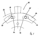
- Fig. 1 shows a centrifugal pendulum device 100 with a pendulum mass support member 102, a two-piece pendulum mass 104 and two spherical rollers 106, 108.
- the pendulum mass support member 102 has a disc-like shape with two side surfaces.
- the pendulum mass carrier part 102 belongs to an output part of a torsional vibration damper.
- the pendulum mass 104 has two pendulum mass parts.
- the pendulum mass parts are arranged on the side surfaces of the pendulum mass support part 102 opposite to each other.
- the pendulum mass parts each have an arcuate shape.
- the pendulum mass parts each have a radially inner edge portion.
- the radially inner edge portion has a circular arc-like shape.
- the pendulum mass parts each have a radially outer edge portion.
- the radially outer edge portion has a circular arc-like shape.
- the pendulum mass parts each have circumferentially facing end portions.
- the pendulum mass parts each have a plate-like shape.
- the pendulum mass parts are arranged congruent with their inner edge portions, their outer edge portions and their end portions to each other.
- the pendulum mass parts are firmly connected.
- the pendulum mass parts are riveted together.
- the pendulum mass support member 102 has for the spherical rollers 106, 108 kidney-like curved openings 110, 112.
- the apertures 110, 112 of the pendulum mass carrier part 102 form spherical roller tracks for the spherical rollers 106, 108.
- the pendulum mass 104 has for the spherical rollers 106, 108 kidney-like curved openings 114, 116.
- the apertures 114, 116 of the pendulum mass 104 form spherical roller tracks for the spherical rollers 106, 108.
- the openings 110, 112 of the pendulum mass support member 102 and the openings 114, 116 of the pendulum mass 104 are bent opposite to each other.
- the pendulum mass 104 is arranged relative to the pendulum mass support member 102 displaceable between two end positions. In the Fig. 1 the pendulum mass 104 is shown in an end position.
- the spherical rollers 106, 108 each have a bolt-like shape with a central portion and two end portions.
- the spherical rollers 106, 108 each have at their central portion and at their end portions to the same diameter.
- the spherical rollers 106, 108 are each arranged with their central portion on the pendulum mass support member 102.
- the pendulum mass parts are arranged at the end portions of the spherical rollers 106, 108.
- the spherical rollers 106, 108 each have a collar.
- the collars each have a larger diameter than the central portion and the end portions.
- Fig. 2 shows a spherical roller track 200 without exemption in plan view.
- Fig. 3 shows a centrifugal pendulum device with a pendulum mass support member 202, a two-piece pendulum mass and a pendulum roller 204 in a straight position in a sectional detail along the in Fig. 2 with AA designated line.
- Fig. 4 shows the centrifugal pendulum device in an inclined position. The pendulum mass is deflected in the representations and is in an end position.
- the spherical roller conveyor 200 is formed by means of an opening 206.
- the aperture 206 is disposed in the pendulum mass support member 202.
- the aperture 206 has a kidney-like shape.
- the opening 206 has a limiting edge 208.
- the edge 208 serves to form the spherical roller track 200.
- the spherical roller track 200 has two end sections 210, 212, a radially outer section 214 and a radially inner section 216.
- the shuttle 204 has a central portion 218 and two end portions 220, 222.
- the shuttle 204 has a collar 224 between the central portion 218 and the end portion 220.
- the shuttle 204 has a collar 226 between the central portion 218 and the end portion 222.
- the shuttle 204 has a cylindrical shape.
- the central portion 218 has a cylindrical surface with which the shuttle 204 runs on a pendulum mass carrier 202.
- the end portion 220 has a cylindrical surface with which the pendulum roller 204 runs on a pendulum mass portion 228 of the pendulum mass.
- the end portion 222 has a cylindrical surface with which the pendulum roller 204 runs on a pendulum mass portion 230 of the pendulum mass.
- the pendulum roller 204 has the same diameter at the central portion 218 and at the end portions 220, 222.
- the collars 224, 226 project beyond the surface of the central portion 218 and the end portions 220, 222.
- an axis of rotation 232 of the pendulum roller 204 is directed parallel to the axis of rotation of the centrifugal pendulum device or the pendulum mass carrier part 202.
- the pendulum mass parts 228, 230 are spaced in the direction of extension of the axis of rotation of the centrifugal pendulum device or the pendulum mass support member 202 of the pendulum mass support member 202 such that the pendulum mass is relatively low friction displaced relative to the pendulum mass support member 202.
- a gap is present, in which the collar 224 engages.
- the collar 226 intervenes.
- the collars 224, 226 serve to space the pendulum mass parts 228, 230 of the pendulum mass carrier 202.
- the pendulum roller 204 may assume an inclined position, as in Fig. 4 shown.
- the axis of rotation 232 of the pendulum roller 204 is then directed obliquely to the axis of rotation of the centrifugal pendulum device or the pendulum mass support member 202.
- the collars 224, 226 may collide with the edge 208 of the aperture 206.
- tilting the spherical roller 204 of the collar 224 dives freely into the opening 206 a.
- tilting of the pendulum roller 204 collides the collar 226 with the edge 208 of the opening 206th FIGS. 2, 3 and 4 refer to the state of the art.
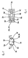
- Fig. 5 shows a spherical roller conveyor 300 with radially inner and end-side exemption 302, 304 in plan view.
- Fig. 6 shows a centrifugal pendulum device with a pendulum mass support member 306, a two-part pendulum mass and a pendulum roller 308 in an oblique position in a sectional detail along the in Fig. 5 with BB designated line.
- the pendulum mass is in Fig. 6 shown deflected and is in an end position.
- the pendulum mass carrier part 306 has two side surfaces 310, 312.
- the release 302 is disposed on the side surface 310.
- the release 304 is disposed on the side surface 312.
- the exemptions 302, 304 are arranged on the radially inner portion 314 and on the end portions 316, 318 of the spherical roller track 300 and the edge 320 of the aperture 322, respectively.
- the exemptions 302, 304 are each designed as an oblique embossing.
- the exemptions 302, 304 form recesses.
- the full strength of the pendulum mass carrier part 306 is present. This ensures a high load capacity. In the in Fig.
- the axis of rotation 324 of the pendulum roller 308 is directed obliquely to the axis of rotation of the centrifugal pendulum device or the pendulum mass carrier part 306.
- the collars 326, 328 of the shuttle roller 308 can dip into the clearances 302, 304 without colliding with the pendulum mass carrier member 306.
- tilting of the pendulum roller 308 of the collar 326 dives freely into the opening 322 a.
- the shuttle 308 immersed the collar 328 freely in the exemption 304 a.
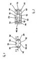
- Fig. 7 shows a spherical roller conveyor 400 with end exemptions 402, 404, 406, 408 in plan view.
- Fig. 8 shows a centrifugal pendulum device with a pendulum mass support member 410, a two-piece pendulum mass and a pendulum roller 412 in an oblique position in a sectional detail along the in Fig. 7 with CC designated line.
- the pendulum mass is in Fig. 8 shown deflected and is in an end position.
- the pendulum mass carrier part 410 has two side surfaces 414, 416.
- the reliefs 402, 404 are disposed on the side surface 414.
- the exemptions 406, 408 are arranged on the side surface 416.
- the exemptions 402, 406 are arranged on the end section 418 of the pendulum roller track 400 or of the edge 420 of the opening 422.
- the exemptions 404, 408 are arranged on the end portion 424 of the spherical roller track 400 and the edge 420 of the opening 422, respectively.
- the exemptions 402, 404, 406, 408 are each designed as an oblique embossing.
- the exemptions 402, 404, 406, 408 form recesses.
- the full strength of the pendulum mass carrier part 410 is present.
- the full strength of the pendulum mass carrier part 410 is present. This ensures a high load capacity.
- the axis of rotation 427 of the pendulum roller 412 is directed obliquely to the axis of rotation of the centrifugal pendulum device or the pendulum mass support member 410.
- the collars 428, 430 of the shuttle roller 412 can be immersed in the exemptions 402, 404, 406, 408 without collision with the pendulum mass support member 410.
Landscapes
- Engineering & Computer Science (AREA)
- General Engineering & Computer Science (AREA)
- Physics & Mathematics (AREA)
- Acoustics & Sound (AREA)
- Aviation & Aerospace Engineering (AREA)
- Mechanical Engineering (AREA)
- Rollers For Roller Conveyors For Transfer (AREA)
- Rolling Contact Bearings (AREA)
- Hybrid Electric Vehicles (AREA)
Description
- Die Erfindung betrifft eine Fliehkraftpendeleinrichtung, insbesondere für einen Antriebsstrang eines brennkraftmaschinengetriebenen Kraftfahrzeugs, aufweisend ein um eine Drehachse drehbares Pendelmassenträgerteil, wenigstens eine an dem Pendelmassenträgerteil unter Fliehkrafteinwirkung verlagerbar angeordnete Pendelmasse und wenigstens eine Pendelrolle mit wenigstens einem Bund zum von dem Pendelmassenträgerteil beabstandeten Führen der wenigstens einen Pendelmasse entlang einer Pendelrollenbahn.
- Aus der
DE 10 2006 028 556 A1 ist Drehmomentübertragungseinrichtung im Antriebsstrang eines Kraftfahrzeugs zur Drehmomentübertragung zwischen einer Antriebseinheit, insbesondere einer Brennkraftmaschine, mit einer Abtriebswelle, insbesondere einer Kurbelwelle, und einem Getriebe mit mindestens einer Getriebeeingangswelle, mit einer Fliehkraftpendeleinrichtung, die mehrere Pendelmassen umfasst, die mit Hilfe von Laufrollen an einer Pendelmassenträgereinrichtung relativ zu dieser bewegbar angebracht sind, und mit mindestens einer Kupplungseinrichtung und/oder mit mindestens einer Drehschwingungsdämpfungseinrichtung, dadurch gekennzeichnet, dass die Laufrollen jeweils mindestens einen Bund aufweisen, der unter Fliehkrafteinwirkung auf die Pendelmasse in axialer Richtung zwischen der Pendelmasse und der Pendelmassenträgereinrichtung angeordnet ist, um die Drehmomentübertragungseinrichtung insbesondere im Hinblick auf die im Betrieb auftretende Geräuschentwicklung zu optimieren. - Eine weitere Fliehkraftpendeleinrichtung ist aus der
DE102009050670 bekannt. - Der Erfindung liegt die Aufgabe zugrunde, eine eingangs genannte Drehmomentübertragungseinrichtung baulich und/oder funktional zu verbessern.
- Die Lösung der Aufgabe erfolgt mit einer Fliehkraftpendeleinrichtung, insbesondere für einen Antriebsstrang eines brennkraftmaschinengetriebenen Kraftfahrzeugs, aufweisend ein um eine Drehachse drehbares Pendelmassenträgerteil, wenigstens eine an dem Pendelmassenträgerteil unter Fliehkrafteinwirkung verlagerbar angeordnete Pendelmasse und wenigstens eine Pendelrolle mit wenigstens einem Bund zum von dem Pendelmassenträgerteil beabstandeten Führen der wenigstens einen Pendelmasse entlang einer Pendelrollenbahn, bei der die Pendelrollenbahn abschnittsweise eine Freistellung für den wenigstens einen Bund aufweist.
- Mithilfe der Fliehkraftpendeleinrichtung kann eine Kompensation von Drehungleichförmigkeiten verbessert sein. Derartige Drehungleichförmigkeiten können insbesondere aufgrund periodisch ablaufender Verbrennungsvorgänge in der Brennkraftmaschine auftreten. Der Antriebsstrang kann einen Drehschwingungsdämpfer aufweisen. Der Drehschwingungsdämpfer kann ein Flanschteil aufweisen. Der Drehschwingungsdämpfer kann ein Eingangsteil und ein Ausgangsteil aufweisen. Das Eingangsteil des Drehschwingungsdämpfers kann einer Brennkraftmaschine zugeordnet sein. Das Ausgangsteil des Drehschwingungsdämpfers kann einer Reibungskupplung zugeordnet sein. Das Ausgangsteil des Drehschwingungsdämpfers kann ein Flanschteil aufweisen. Der Drehschwingungsdämpfer kann ein Zweimassenschwungrad sein. Der Antriebsstrang kann eine Reibungskupplung aufweisen. Die Reibungskupplung kann ein Flanschteil aufweisen. Die Reibungskupplung kann eine Kupplungsscheibe aufweisen. Der Antriebsstrang kann einen Drehmomentwandler aufweisen. Der Drehmomentwandler kann ein Flanschteil aufweisen. Das Flanschteil der Reibungskupplung kann das Pendelmassenträgerteil sein. Die Kupplungsscheibe der Reibungskupplung kann das Pendelmassenträgerteil sein. Das Flanschteil des Drehschwingungsdämpfers kann das Pendelmassenträgerteil sein. Das Flanschteil des Ausgangsteils des Drehschwingungsdämpfers kann das Pendelmassenträgerteil sein. Das Flanschteil des Drehmomentwandlers kann das Pendelmassenträgerteil sein.
- Die Pendelrollenbahn kann an dem Pendelmassenträgerteil angeordnet sein. Die Pendelrollenbahn kann an der wenigstens einen Pendelmasse angeordnet sein. Für die wenigstens eine Pendelmasse kann wenigstens eine Pendelrollenbahn vorgesehen sein. Für die wenigstens eine Pendelmasse können zwei Pendelrollenbahnen vorgesehen sein. Die Pendelrollenbahn kann mithilfe eines Durchbruchs gebildet sein. Der Durchbruch kann eine nierenartige Form aufweisen. Der Durchbruch kann einen umlaufenden Rand mit Randabschnitten aufweisen. Ein Randabschnitt kann eine Pendelrollenbahn bilden. Ein Randabschnitt kann einen Anschlag bilden.
- Die wenigstens eine Pendelmasse kann entlang einer vorgegebenen Bahn verlagerbar sein. Die wenigstens eine Pendelmasse kann zwischen einer ersten Endlage und einer zweiten Endlage verlagerbar sein. Die wenigstens eine Pendelmasse kann zur Drehachse der Fliehkraftpendeleinrichtung exzentrisch angeordnet sein. Die Fliehkraftpendeleinrichtung kann mehrere, insbesondere zwei, drei öder vier Pendelmassen aufweisen. Die wenigstens eine Pendelmasse kann eine kreisringbogenartige Form aufweisen. Die kreisringbogenartige Form der wenigstens einen Pendelmasse kann sich über einen Mittelpunktswinkel von ca. 160°-190°, insbesondere von ca. 180°, erstrecken. Die kreisringbogenartige Form der wenigstens einen Pendelmasse kann sich über einen Mittelpunktswinkel von ca. 100°-130°, insbesondere von ca. 120°, erstrecken. Die kreisringbogenartige Form der wenigstens einen Pendelmasse kann sich über einen Mittelpunktswinkel von ca. 70°-100°, insbesondere von ca. 90°, erstrecken.
- Die wenigstens eine Pendelmasse kann ein einziges Pendelmasseteil aufweisen. Die wenigstens eine Pendelmasse kann zwei Pendelmasseteile aufweisen. Ein Pendelmasseteil kann wenigstens einen Durchbruch zur Bildung einer Pendelrollenbahn aufweisen. Die zwei Pendelmasseteile der wenigstens einen Pendelmasse können einander in Erstreckungsrichtung der Drehachse gegenüberliegend angeordnet sein. Die zwei Pendelmasseteile der wenigstens einen Pendelmasse können einander gegenüberliegend beidseits des Pendelmassenträgerteils angeordnet sein. Die zwei Pendelmasseteile der wenigstens einen Pendelmasse können mit ihren Pendelrollenbahnen fluchtend angeordnet sein. Die zwei Pendelmasseteile der wenigstens einen Pendelmasse können miteinander fest verbunden sein. Die zwei Pendelmasseteile der wenigstens einen Pendelmasse können miteinander vernietet sein.
- Die wenigstens eine Pendelrolle kann zur verlagerbaren Anordnung der wenigstens einen Pendelmasse an dem Pendelmassenträgerteil dienen. Die wenigstens eine Pendelrolle kann eine zylinderartige Form aufweisen. Die wenigstens eine Pendelrolle kann eine Drehachse aufweisen. Die Drehachse der wenigstens einen Pendelrolle kann zur Drehachse der Fliehkraftpendeleinrichtung parallel sein. Die wenigstens eine Pendelrolle kann zwei erste Abschnitte aufweisen, die Pendelmasseteilen einer Pendelmasse zugeordnet sind. Die wenigstens eine Pendelrolle kann einen zweiten Abschnitt aufweisen, der dem Pendelmassenträgerteil zugeordnet ist. Die Abschnitte der wenigstens einen Pendelrolle können in Erstreckungsrichtung der Drehachse nebeneinander angeordnet sein. Der zweite Abschnitt kann zwischen den ersten Abschnitten angeordnet sein. Die wenigstens eine Pendelrolle kann an dem zweiten Abschnitt einen größeren Durchmesser als an den ersten Abschnitten aufweisen. Die wenigstens eine Pendelrolle kann eine stufenbolzenartige Form aufweisen. Die wenigstens eine Pendelrolle kann an dem zweiten Abschnitt und an den ersten Abschnitten gleiche Durchmesser aufweisen. Der wenigstens eine Bund der Pendelrolle kann zwischen einem ersten Abschnitt und dem zweiten Abschnitt angeordnet sein. Die wenigstens eine Pendelrolle kann zwei Bunde aufweisen. Die wenigstens eine Pendelrolle kann an dem wenigstens einen Bund einen größeren Durchmesser als an dem ersten Abschnitt und/oder an dem zweiten Abschnitt aufweisen. Der wenigstens eine Bund kann zum Zentrieren der wenigstens einen Pendelrolle dienen. Der wenigstens eine Bund kann dazu dienen, die wenigstens eine Pendelmasse bei Verlagerung von dem Pendelmassenträgerteil beabstandet zu halten, um eine Reibung zu verringern. Die Freistellung kann eine Ausnehmung sein. Die Freistellung kann zur Aufnahme des wenigstens einen Bunds bei einer Schiefstellung der wenigstens einen Pendelrolle dienen.
- Die erfindungsgemäße Fliehkraftpendeleinrichtung ermöglicht einen Schutz des wenigstens einen Bunds und des Pendelmassenträgerteils auch bei Schiefstellung der wenigstens einen Pendelrolle. Der wenigstens eine Bund kann bei Schiefstellung der wenigstens einen Pendelrolle ohne Beschädigungsgefahr in den Bereich der Freistellung eintauchen. Der wenigstens eine Bund und das Pendelmassenträgerteil sind vor einer Kollision geschützt. Ein Verschleiß des wenigstens einen Bunds und des Pendelmassenträgerteils ist verringert.
- Die Pendelrollenbahn kann zwei Endabschnitte aufweisen und die Freistellung kann an den Endabschnitten der Pendelrollenbahn angeordnet sein. Die Endabschnitte können in Umfangsrichtung der Fliehkraftpendeleinrichtung gerichtet sein. Die Pendelrollenbahn kann einen radial inneren Abschnitt aufweisen und die Freistellung kann an dem radial inneren Abschnitt der Pendelrollenbahn angeordnet sein. Die Pendelrollenbahn kann mit der Freistellung an dem Pendelmassenträgerteil angeordnet sein. Die Pendelrollenbahn kann mit der Freistellung an der wenigstens einen Pendelmasse angeordnet sein. Die Freistellung kann an dem Pendelmassenträgerteil oder an der wenigstens einen Pendelmasse in Erstreckungsrichtung der Drehachse beidseits angeordnet sein. Die Freistellung kann mithilfe einer Anprägung gebildet sein. Die Anprägung kann mit einer Schräge, einer Fase oder einem Radius ausgeführt sein.
- Zusammenfassend und mit anderen Worten dargestellt ergeben sich somit durch die Erfindung unter anderem angeprägte Rollenbahnen bei einem Fliehkraftpendel. Eine Rollenbahn im Flansch kann an der Stelle, an der eine Kollisionsgefahr besteht, mit einer Anprägung versehen sein, in die ein Zentrierbord gefahrlos eintauchen kann Aus Gründen der Flächenpressung zwischen einer Rolle und einer Flanschbahn kann die Anprägung nur an den Bahnenden bzw. radial innen angebracht sein. In einem "normalen" Schwingbereich der Rolle, bzw. im Bereich einer maximalen Flächenpressung kann der volle Blechquerschnitt vorhanden sein. Die Anprägung kann an Pendelmassen oder an einem Flansch angebracht sein.
- Mit "kann" sind insbesondere optionale Merkmale der Erfindung bezeichnet. Demzufolge gibt es jeweils ein Ausführungsbeispiel der Erfindung, das das jeweilige Merkmal oder die jeweiligen Merkmale aufweist.
- Nachfolgend werden Ausführungsbeispiele der Erfindung unter Bezugnahme auf Figuren näher beschrieben. Aus dieser Beschreibung ergeben sich weitere Merkmale und Vorteile. Konkrete Merkmale dieser Ausführungsbeispiele können allgemeine Merkmale der Erfindung darstellen. Mit anderen Merkmalen verbundene Merkmale dieser Ausführungsbeispiele können auch einzelne Merkmale der Erfindung darstellen.
- Es zeigen schematisch und beispielhaft:
- Fig. 1
- eine Fliehkraftpendeleinrichtung mit einem Pendelmassenträgerteil, einer Pendelmasse und zwei Pendelrollen,
- Fig. 2
- eine Pendelrollenbahn ohne Freistellung in Draufsicht,
- Fig. 3
- eine Fliehkraftpendeleinrichtung mit einem Pendelmassenträgerteil, einer zweiteiligen Pendelmasse und einer Pendelrolle in gerader Position in ausschnittsweiser Schnittdarstellung entlang der in
Fig. 2 mit A-A bezeichneten Linie, - Fig. 4
- eine Fliehkraftpendeleinrichtung mit einem Pendelmassenträgerteil, einer zweiteiligen Pendelmasse und einer Pendelrolle in schräger Position in ausschnittsweiser Schnittdarstellung entlang der in
Fig. 2 mit A-A bezeichneten Linie, - Fig. 5
- eine Pendelrollenbahn mit radial innerer und endseitiger Freistellung in Draufsicht,
- Fig. 6
- eine Fliehkraftpendeleinrichtung mit einem Pendelmassenträgerteil, einer zweiteiligen Pendelmasse und einer Pendelrolle in schräger Position in ausschnittsweiser Schnittdarstellung entlang der in
Fig. 5 mit B-B bezeichneten Linie, - Fig. 7
- eine Pendelrollenbahn mit endseitigen Freistellungen in Draufsicht und
- Fig. 8
- eine Fliehkraftpendeleinrichtung mit einem Pendelmassenträgerteil, einer zweiteiligen Pendelmasse und einer Pendelrolle in schräger Position in ausschnittsweiser Schnittdarstellung entlang der in
Fig. 7 mit C-C bezeichneten Linie, -
Fig. 1 zeigt eine Fliehkraftpendeleinrichtung 100 mit einem Pendelmassenträgerteil 102, einer zweiteiligen Pendelmasse 104 und zwei Pendelrollen 106, 108. Das Pendelmassenträgerteil 102 weist eine scheibenartige Form mit zwei Seitenflächen auf. Das Pendelmassenträgerteil 102 gehört zu einem Ausgangsteil eines Drehschwingungsdämpfers. Die Pendelmasse 104 weist zwei Pendelmasseteile auf. Die Pendelmasseteile sind an den Seitenflächen des Pendelmassenträgerteils 102 einander gegenüberliegend angeordnet. Die Pendelmasseteile weisen jeweils eine bogenartige Form auf. Die Pendelmasseteile weisen jeweils einen radial inneren Randabschnitt auf. Der radial innere Randabschnitt weist eine kreisbogenartige Form auf. Die Pendelmasseteile weisen jeweils einen radial äußeren Randabschnitt auf. Der radial äußere Randabschnitt weist eine kreisbogenartige Form auf. Die Pendelmasseteile weisen jeweils in Umfangsrichtung weisende Endabschnitte auf. Die Pendelmasseteile weisen jeweils eine plattenartige Form auf. Die Pendelmasseteile sind mit ihren inneren Randabschnitten, ihren äußeren Randabschnitten und ihren Endabschnitten zueinander deckungsgleich angeordnet. Die Pendelmasseteile sind miteinander fest verbunden. Die Pendelmasseteile sind miteinander vernietet. - Zur verlagerbaren Anordnung der Pendelmasse 104 an dem Pendelmassenträgerteil 102 dienen die zwei Pendelrollen 106, 108. Das Pendelmassenträgerteil 102 weist für die Pendelrollen 106, 108 nierenartig gebogene Durchbrechungen 110, 112 auf. Die Durchbrechungen 110, 112 des Pendelmassenträgerteils 102 bilden Pendelrollenbahnen für die Pendelrollen 106, 108. Die Pendelmasse 104 weist für die Pendelrollen 106, 108 nierenartig gebogene Durchbrechungen 114, 116 auf. Die Durchbrechungen 114, 116 der Pendelmasse 104 bilden Pendelrollenbahnen für die Pendelrollen 106, 108. Die Durchbrechungen 110, 112 des Pendelmassenträgerteils 102 und die Durchbrechungen 114, 116 der Pendelmasse 104 sind einander entgegengesetzt gebogen. Die Pendelmasse 104 ist relativ zu dem Pendelmassenträgerteil 102 zwischen zwei Endlagen verlagerbar angeordnet. In der
Fig. 1 ist die Pendelmasse 104 in einer Endlage gezeigt. - Die Pendelrollen 106, 108 weisen jeweils eine bolzenartige Form mit einem Mittelabschnitt und zwei Endabschnitten auf. Die Pendelrollen 106, 108 weisen jeweils an ihrem Mittelabschnitt und an ihren Endabschnitten gleiche Durchmesser auf. Die Pendelrollen 106, 108 sind jeweils mit ihrem Mittelabschnitt an dem Pendelmassenträgerteil 102 angeordnet. Die Pendelmasseteile sind an den Endabschnitten der Pendelrollen 106, 108 angeordnet. Zwischen den Endabschnitten und dem Mittelabschnitt weisen die Pendelrollen 106, 108 jeweils einen Bund auf. Die Bünde weisen jeweils einen größeren Durchmesser als der Mittelabschnitt und die Endabschnitte auf.
-
Fig. 2 zeigt eine Pendelrollenbahn 200 ohne Freistellung in Draufsicht.Fig. 3 zeigt eine Fliehkraftpendeleinrichtung mit einem Pendelmassenträgerteil 202, einer zweiteiligen Pendelmasse und einer Pendelrolle 204 in gerader Position in ausschnittsweiser Schnittdarstellung entlang der inFig. 2 mit A-A bezeichneten Linie.Fig. 4 zeigt die Fliehkraftpendeleinrichtung in schräger Position. Die Pendelmasse ist in den Darstellungen jeweils ausgelenkt und befindet sich in einer Endlage. - Die Pendelrollenbahn 200 ist mithilfe einer Durchbrechung 206 gebildet. Die Durchbrechung 206 ist in dem Pendelmassenträgerteil 202 angeordnet. Die Durchbrechung 206 weist eine nierenartige Form auf. Die Durchbrechung 206 weist einen begrenzenden Rand 208 auf. Der Rand 208 dient zur Bildung der Pendelrollenbahn 200. Die Pendelrollenbahn 200 weist zwei Endabschnitte 210, 212, einen radial äußeren Abschnitt 214 und einen radial inneren Abschnitt 216 auf.
- Die Pendelrolle 204 weist eine Mittelabschnitt 218 und zwei Endabschnitte 220, 222 auf. Die Pendelrolle 204 weist zwischen dem Mittelabschnitt 218 und dem Endabschnitt 220 einen Bund 224 auf. Die Pendelrolle 204 weist zwischen dem Mittelabschnitt 218 und dem Endabschnitt 222 einen Bund 226 auf. Die Pendelrolle 204 weist eine zylindrische Form auf. Der Mittelabschnitt 218 weist eine zylindrische Oberfläche auf, mit der die Pendelrolle 204 an einem Pendelmasseträgerteil 202 läuft. Der Endabschnitt 220 weist eine zylindrische Oberfläche auf, mit der die Pendelrolle 204 an einem Pendelmasseteil 228 der Pendelmasse läuft. Der Endabschnitt 222 weist eine zylindrische Oberfläche auf, mit der die Pendelrolle 204 an einem Pendelmasseteil 230 der Pendelmasse läuft. Die Pendelrolle 204 weist an dem Mittelabschnitt 218 und an den Endabschnitten 220, 222 gleiche Durchmesser auf. Die Bünde 224, 226 stehen über die Oberfläche des Mittelabschnitts 218 und der Endabschnitte 220, 222 über. In der geraden Position ist eine Drehachse 232 der Pendelrolle 204 zur Drehachse der Fliehkraftpendeleinrichtung bzw. des Pendelmassenträgerteils 202 parallel gerichtet.
- Die Pendelmasseteile 228, 230 sind in Erstreckungsrichtung der Drehachse der Fliehkraftpendeleinrichtung bzw. des Pendelmassenträgerteils 202 von dem Pendelmassenträgerteil 202 derart beabstandet, dass die Pendelmasse relativ zu dem Pendelmassenträgerteil 202 reibungsarm verlagerbar ist. Zwischen dem Pendelmasseteil 228 und dem Pendelmassenträgerteil 202 ist ein Zwischenraum vorhanden, in den der Bund 224 eingreift. Zwischen dem Pendelmasseteil 230 und dem Pendelmassenträgerteil 202 ist ein Zwischenraum vorhanden, in den der Bund 226 eingreift. Die Bünde 224, 226 dienen zur Beabstandung der Pendelmasseteile 228, 230 von dem Pendelmassenträgerteil 202.
- Bei einem Betrieb der Fliehkraftpendeleinrichtung, insbesondere bei einem Start-Stopp-Betrieb einer Brennkraftmaschine, kann die Pendelrolle 204 unter Umständen eine schräge Position einnehmen, wie in
Fig. 4 gezeigt. Die Drehachse 232 der Pendelrolle 204 ist dann zur Drehachse der Fliehkraftpendeleinrichtung bzw. des Pendelmassenträgerteils 202 schräg gerichtet. Die Bünde 224, 226 können mit dem Rand 208 der Durchbrechung 206 kollidieren. Bei der inFig. 4 gezeigten Schrägstellung der Pendelrolle 204 taucht der Bund 224 frei in die Durchbrechung 206 ein. Bei der inFig. 4 gezeigten Schrägstellung der Pendelrolle 204 kollidiert der Bund 226 mit dem Rand 208 der Durchbrechung 206.Fig. 2, Fig. 3 und Fig. 4 beziehen sich auf den Stand der Technik. -
Fig. 5 zeigt eine Pendelrollenbahn 300 mit radial innerer und endseitiger Freistellung 302, 304 in Draufsicht.Fig. 6 zeigt eine Fliehkraftpendeleinrichtung mit einem Pendelmassenträgerteil 306, einer zweiteiligen Pendelmasse und einer Pendelrolle 308 in schräger Position in ausschnittsweiser Schnittdarstellung entlang der inFig. 5 mit B-B bezeichneten Linie. Die Pendelmasse ist inFig. 6 ausgelenkt gezeigt und befindet sich in einer Endlage. Das Pendelmassenträgerteil 306 weist zwei Seitenflächen 310, 312 auf. Die Freistellung 302 ist an der Seitenfläche 310 angeordnet. Die Freistellung 304 ist an der Seitenfläche 312 angeordnet. Die Freistellungen 302, 304 sind an dem radial inneren Abschnitt 314 und an den Endabschnitten 316, 318 der Pendelrollenbahn 300 bzw. des Rands 320 der Durchbrechung 322 angeordnet. Die Freistellungen 302, 304 sind jeweils als schräge Anprägung ausgeführt. Die Freistellungen 302, 304 bilden Ausnehmungen. An dem radial äußeren Abschnitt 323 der Pendelrollenbahn 300 bzw. des Rands 320 der Durchbrechung 322 ist die volle Stärke des Pendelmassenträgerteils 306 vorhanden. Damit ist eine hohe Tragfähigkeit gewährleistet. In der inFig. 6 gezeigten schrägen Position der Pendelrolle 308 ist die Drehachse 324 der Pendelrolle 308 zur Drehachse der Fliehkraftpendeleinrichtung bzw. des Pendelmassenträgerteils 306 schräg gerichtet. Die Bünde 326, 328 der Pendelrolle 308 können ohne Kollision mit dem Pendelmassenträgerteil 306 in die Freistellungen 302, 304 eintauchen. Bei der inFig. 6 gezeigten Schrägstellung der Pendelrolle 308 taucht der Bund 326 frei in die Durchbrechung 322 ein. Bei der inFig. 6 gezeigten Schrägstellung der Pendelrolle 308 taucht der Bund 328 frei in die Freistellung 304 ein. Im Übrigen wird ergänzend insbesondere aufFig. 1 ,Fig. 2, Fig. 3 und Fig. 4 sowie die zugehörige Beschreibung verwiesen. -
Fig. 7 zeigt eine Pendelrollenbahn 400 mit endseitigen Freistellungen 402, 404, 406, 408 in Draufsicht.Fig. 8 zeigt eine Fliehkraftpendeleinrichtung mit einem Pendelmassenträgerteil 410, einer zweiteiligen Pendelmasse und einer Pendelrolle 412 in schräger Position in ausschnittsweiser Schnittdarstellung entlang der inFig. 7 mit C-C bezeichneten Linie. Die Pendelmasse ist inFig. 8 ausgelenkt gezeigt und befindet sich in einer Endlage. Das Pendelmassenträgerteil 410 weist zwei Seitenflächen 414, 416 auf. Die Freistellungen 402, 404 sind an der Seitenfläche 414 angeordnet. Die Freistellungen 406, 408 sind an der Seitenfläche 416 angeordnet. Die Freistellungen 402, 406 sind an dem Endabschnitt 418 der Pendelrollenbahn 400 bzw. des Rands 420 der Durchbrechung 422 angeordnet. Die Freistellungen 404, 408 sind an dem Endabschnitt 424 der Pendelrollenbahn 400 bzw. des Rands 420 der Durchbrechung 422 angeordnet. Die Freistellungen 402, 404, 406, 408 sind jeweils als schräge Anprägung ausgeführt. Die Freistellungen 402, 404, 406, 408 bilden Ausnehmungen. An dem radial inneren Abschnitt 425 der Pendelrollenbahn 400 bzw. des Rands 420 der Durchbrechung 422 ist die volle Stärke des Pendelmassenträgerteils 410 vorhanden. An dem radial äußeren Abschnitt 426 der Pendelrollenbahn 400 bzw. des Rands 420 der Durchbrechung 422 ist die volle Stärke des Pendelmassenträgerteils 410 vorhanden. Damit ist eine hohe Tragfähigkeit gewährleistet. In der inFig. 6 gezeigten schrägen Position der Pendelrolle 412 ist die Drehachse 427 der Pendelrolle 412 zur Drehachse der Fliehkraftpendeleinrichtung bzw. des Pendelmassenträgerteils 410 schräg gerichtet. Die Bünde 428, 430 der Pendelrolle 412 können ohne Kollision mit dem Pendelmassenträgerteil 410 in die Freistellungen 402, 404, 406, 408 eintauchen. Bei der inFig. 6 gezeigten Schrägstellung der Pendelrolle 412 taucht der Bund 428 frei in die Durchbrechung 422 ein. Bei der inFig. 6 gezeigten Schrägstellung der Pendelrolle 412 taucht der Bund 430 frei in die Freistellung 408 ein. Im Übrigen wird ergänzend insbesondere aufFig. 1 ,Fig. 2, Fig. 3 und Fig. 4 sowie die zugehörige Beschreibung verwiesen. -
- 100
- Fliehkraftpendeleinrichtung
- 102
- Pendelmassenträgerteil
- 104
- Pendelmasse
- 106
- Pendelrolle
- 108
- Pendelrolle
- 110
- Durchbrechung
- 112
- Durchbrechung
- 114
- Durchbrechung
- 116
- Durchbrechung
- 200
- Pendelrollenbahn
- 202
- Pendelmassenträgerteil
- 204
- Pendelrolle
- 206
- Durchbrechung
- 208
- Rand
- 210
- Endabschnitt der Pendelrollenbahn
- 212
- Endabschnitt der Pendelrollenbahn
- 214
- radial äußeren Abschnitt
- 216
- radial inneren Abschnitt
- 218
- Mittelabschnitt
- 220
- Endabschnitt der Pendelrolle
- 222
- Endabschnitt der Pendelrolle
- 224
- Bund
- 226
- Bund
- 228
- Pendelmasseteil
- 230
- Pendelmasseteil
- 232
- Drehachse
- 300
- Pendelrollenbahn
- 302
- Freistellung
- 304
- Freistellung
- 306
- Pendelmassenträgerteil
- 308
- Pendelrolle
- 310
- Seitenfläche
- 312
- Seitenfläche
- 314
- radial innerer Abschnitt
- 316
- Endabschnitt der Pendelrollenbahn
- 318
- Endabschnitt der Pendelrollenbahn
- 320
- Rand
- 322
- Durchbrechung
- 323
- radial äußerer Abschnitt
- 324
- Drehachse
- 326
- Bund
- 328
- Bund
- 400
- Pendelrollenbahn
- 402
- Freistellung
- 404
- Freistellung
- 406
- Freistellung
- 408
- Freistellung
- 410
- Pendelmassenträgerteil
- 412
- Pendelrolle
- 414
- Seitenfläche
- 416
- Seitenfläche
- 418
- Endabschnitt der Pendelrollenbahn
- 420
- Rand
- 422
- Durchbrechung
- 424
- Endabschnitt der Pendelrollenbahn
- 425
- radial innerer Abschnitt
- 426
- radial äußerer Abschnitt
- 427
- Drehachse
- 428
- Bund
- 430
- Bund
Claims (8)
- Fliehkraftpendeleinrichtung (100), insbesondere für einen Antriebsstrang eines brennkraftmaschinengetriebenen Kraftfahrzeugs, aufweisend ein um eine Drehachse drehbares Pendelmassenträgerteil (102, 306, 410), wenigstens eine an dem Pendelmassenträgerteil (102, 306, 410) unter Fliehkrafteinwirkung verlagerbar angeordnete Pendelmasse (104) und wenigstens eine Pendelrolle (106, 108, 308, 412) mit wenigstens einem Bund (326, 328, 428, 430) zum von dem Pendelmassenträgerteil (102, 306, 410) beabstandeten Führen der wenigstens einen Pendelmasse (104) entlang einer Pendelrollenbahn (300, 400), dadurch gekennzeichnet, dass die Pendelrollenbahn (300, 400) abschnittsweise eine Freistellung (302, 304, 402, 404, 406, 408) für den wenigstens einen Bund (326, 328, 428, 430) aufweist.
- Fliehkraftpendeleinrichtung (100) nach Anspruch 1, dadurch gekennzeichnet, dass die Pendelrollenbahn (300, 400) zwei Endabschnitte (316, 318, 418, 424) aufweist und die Freistellung (302, 304, 402, 404, 406, 408) an den Endabschnitten (316, 318, 418, 424) der Pendelrollenbahn (300, 400) angeordnet ist.
- Fliehkraftpendeleinrichtung (100) nach einem der vorhergehenden Ansprüche, dadurch gekennzeichnet, dass die Pendelrollenbahn (300) einen radial inneren Abschnitt (314) aufweist und die Freistellung (302, 304) an dem radial inneren Abschnitt (314) der Pendelrollenbahn (300) angeordnet ist.
- Fliehkraftpendeleinrichtung (100) nach einem der vorhergehenden Ansprüche, dadurch gekennzeichnet, dass die Pendelrollenbahn (300, 400) mit der Freistellung (302, 304, 402, 404, 406, 408) an dem Pendelmassenträgerteil (102, 306, 410) angeordnet ist.
- Fliehkraftpendeleinrichtung (100) nach einem der vorhergehenden Ansprüche, dadurch gekennzeichnet, dass die Pendelrollenbahn mit der Freistellung an der wenigstens einen Pendelmasse (104) angeordnet ist.
- Fliehkraftpendeleinrichtung (100) nach einem der vorhergehenden Ansprüche, dadurch gekennzeichnet, dass die Freistellung (302, 304, 402, 404, 406, 408) an dem Pendelmassenträgerteil (102, 306, 410) oder an der wenigstens einen Pendelmasse (104) in Erstreckungsrichtung der Drehachse beidseits angeordnet ist.
- Fliehkraftpendeleinrichtung (100) nach einem der vorhergehenden Ansprüche, dadurch gekennzeichnet, dass die Freistellung (302, 304, 402, 404, 406, 408) mithilfe einer Anprägung gebildet ist.
- Fliehkraftpendeleinrichtung (100) nach Anspruch 7, dadurch gekennzeichnet, dass die Anprägung mit einer Schräge, einer Fase oder einem Radius ausgeführt ist.
Applications Claiming Priority (2)
| Application Number | Priority Date | Filing Date | Title |
|---|---|---|---|
| DE102012206038 | 2012-04-13 | ||
| PCT/EP2013/057165 WO2013152994A1 (de) | 2012-04-13 | 2013-04-05 | Fliehkraftpendeleinrichtung |
Publications (2)
| Publication Number | Publication Date |
|---|---|
| EP2836739A1 EP2836739A1 (de) | 2015-02-18 |
| EP2836739B1 true EP2836739B1 (de) | 2016-03-30 |
Family
ID=48227187
Family Applications (1)
| Application Number | Title | Priority Date | Filing Date |
|---|---|---|---|
| EP13719437.9A Not-in-force EP2836739B1 (de) | 2012-04-13 | 2013-04-05 | Fliehkraftpendeleinrichtung |
Country Status (4)
| Country | Link |
|---|---|
| EP (1) | EP2836739B1 (de) |
| CN (1) | CN104271982B (de) |
| DE (2) | DE112013002026A5 (de) |
| WO (1) | WO2013152994A1 (de) |
Families Citing this family (5)
| Publication number | Priority date | Publication date | Assignee | Title |
|---|---|---|---|---|
| DE102012221956A1 (de) * | 2012-11-30 | 2014-06-05 | Schaeffler Technologies Gmbh & Co. Kg | Drehmomentübertragungseinrichtung und Antriebsstrang mit Drehmomentübertragungseinrichtung |
| DE102014207961A1 (de) * | 2014-04-28 | 2015-10-29 | Zf Friedrichshafen Ag | Tilgerschwingungsdämpfer und Verfahren zum Bereitstellen eines Tilgerschwingungsdämpfers |
| DE102015212180A1 (de) * | 2015-06-30 | 2017-01-05 | Schaeffler Technologies AG & Co. KG | Fliehkraftpendel |
| DE102019101166A1 (de) * | 2019-01-17 | 2020-07-23 | Schaeffler Technologies AG & Co. KG | Fliehkraftpendel |
| DE102020105174A1 (de) | 2020-02-27 | 2021-09-02 | Schaeffler Technologies AG & Co. KG | Fliehkraftpendel mit axial ausgestellter Rollenbahn; sowie Drehmomentübertragungsvorrichtung |
Family Cites Families (7)
| Publication number | Priority date | Publication date | Assignee | Title |
|---|---|---|---|---|
| US1882281A (en) * | 1930-09-23 | 1932-10-11 | Packard Motor Car Co | Internal combustion engine |
| US6719537B2 (en) * | 2001-03-14 | 2004-04-13 | Kabushiki Kaisha Toyota Jidoshokki | Compressor and pulley for compressor |
| NL1023120C2 (nl) * | 2002-04-10 | 2006-04-25 | Luk Lamellen & Kupplungsbau | Werkwijze voor het optimaliseren van schakels van een schakelketting alsmede schakels voor een schakelketting. |
| DE102006028556B4 (de) | 2005-07-11 | 2019-10-10 | Schaeffler Technologies AG & Co. KG | Drehmomentübertragungseinrichtung |
| EP1865222A1 (de) * | 2006-06-10 | 2007-12-12 | LuK Lamellen und Kupplungsbau Beteiligungs KG | Fliehkraftpendeleinrichtung |
| DE102009050670A1 (de) * | 2008-11-18 | 2010-05-20 | Luk Lamellen Und Kupplungsbau Beteiligungs Kg | Einstückiges Pendel |
| DE102010028849A1 (de) * | 2010-05-11 | 2011-11-17 | Zf Friedrichshafen Ag | Schwingungstilger |
-
2013
- 2013-04-05 EP EP13719437.9A patent/EP2836739B1/de not_active Not-in-force
- 2013-04-05 DE DE112013002026.2T patent/DE112013002026A5/de not_active Withdrawn
- 2013-04-05 CN CN201380019726.3A patent/CN104271982B/zh not_active Expired - Fee Related
- 2013-04-05 WO PCT/EP2013/057165 patent/WO2013152994A1/de not_active Ceased
- 2013-04-05 DE DE102013206015A patent/DE102013206015A1/de not_active Withdrawn
Also Published As
| Publication number | Publication date |
|---|---|
| EP2836739A1 (de) | 2015-02-18 |
| WO2013152994A1 (de) | 2013-10-17 |
| CN104271982A (zh) | 2015-01-07 |
| CN104271982B (zh) | 2016-02-24 |
| DE112013002026A5 (de) | 2015-02-05 |
| DE102013206015A1 (de) | 2013-10-17 |
Similar Documents
| Publication | Publication Date | Title |
|---|---|---|
| EP2861889B1 (de) | Fliehkraftpendeleinrichtung mit einer pendelrolle | |
| DE102012204222A1 (de) | Fliehkraftpendeleinrichtung | |
| DE102016222247A1 (de) | Fliehkraftpendeleinrichtung | |
| EP2850337B1 (de) | Pendelrolle für eine fliehkraftpendeleinrichtung und fliehkraftpendeleinrichtung mit einer derartigen pendelrolle | |
| WO2015043587A1 (de) | Fliehkraftpendeleinrichtung | |
| DE102016125380A1 (de) | Fliehkraftpendeleinrichtung und Drehmomentübertragungseinrichtung | |
| DE102016205420A1 (de) | Fliehkraftpendeleinrichtung und Drehmomentübertragungseinrichtung | |
| EP2888505A1 (de) | Drehschwingungsdämpfer | |
| DE102012210575A1 (de) | Fliehkraftpendeleinrichtung undEinsatz für eine Fliehkraftpendeleinrichtung | |
| WO2013152994A1 (de) | Fliehkraftpendeleinrichtung | |
| WO2018010722A1 (de) | Fliehkraftpendel | |
| DE102019110130A1 (de) | Drehschwingungsdämpfer | |
| DE102015205754A1 (de) | Pendelmasse und Fliehkraftpendeleinrichtung | |
| DE102015211772A1 (de) | Pendelrolle und Fliehkraftpendeleinrichtung | |
| DE102015209506A1 (de) | Fliehkraftpendeleinrichtung und Drehmomentübertragungseinrichtung | |
| DE102012220960A1 (de) | Fliehkraftpendeleinrichtung | |
| DE102012212895A1 (de) | Fliehkraftpendeleinrichtung | |
| DE102012208264A1 (de) | Pendelrolle für eine Fliehkraftpendeleinrichtung und Fliehkraftpendeleinrichtung mit einer derartigen Pendelrolle | |
| DE102015213903A1 (de) | Fliehkraftpendeleinrichtung und Drehmomentübertragungseinrichtung | |
| DE102015207738A1 (de) | Fliehkraftpendeleinrichtung und Drehschwingungsdämpfer | |
| DE102018127455A1 (de) | Fliehkraftpendeleinrichtung und Drehmomentübertragungseinrichtung | |
| EP2904289B1 (de) | Drehschwingungsdämpfer | |
| DE102020112663A1 (de) | Fliehkraftpendel | |
| DE102016215145A1 (de) | Fliehkraftpendel | |
| DE102014217471A1 (de) | Laufbahnanordnung, Pendelmasseträgerteil, Pendelmasse und Fliehkraftpendeleinrichtung |
Legal Events
| Date | Code | Title | Description |
|---|---|---|---|
| PUAI | Public reference made under article 153(3) epc to a published international application that has entered the european phase |
Free format text: ORIGINAL CODE: 0009012 |
|
| 17P | Request for examination filed |
Effective date: 20141113 |
|
| AK | Designated contracting states |
Kind code of ref document: A1 Designated state(s): AL AT BE BG CH CY CZ DE DK EE ES FI FR GB GR HR HU IE IS IT LI LT LU LV MC MK MT NL NO PL PT RO RS SE SI SK SM TR |
|
| AX | Request for extension of the european patent |
Extension state: BA ME |
|
| RAP1 | Party data changed (applicant data changed or rights of an application transferred) |
Owner name: SCHAEFFLER TECHNOLOGIES AG & CO. KG |
|
| DAX | Request for extension of the european patent (deleted) | ||
| GRAP | Despatch of communication of intention to grant a patent |
Free format text: ORIGINAL CODE: EPIDOSNIGR1 |
|
| INTG | Intention to grant announced |
Effective date: 20151207 |
|
| GRAS | Grant fee paid |
Free format text: ORIGINAL CODE: EPIDOSNIGR3 |
|
| GRAA | (expected) grant |
Free format text: ORIGINAL CODE: 0009210 |
|
| AK | Designated contracting states |
Kind code of ref document: B1 Designated state(s): AL AT BE BG CH CY CZ DE DK EE ES FI FR GB GR HR HU IE IS IT LI LT LU LV MC MK MT NL NO PL PT RO RS SE SI SK SM TR |
|
| REG | Reference to a national code |
Ref country code: GB Ref legal event code: FG4D Free format text: NOT ENGLISH |
|
| REG | Reference to a national code |
Ref country code: CH Ref legal event code: EP |
|
| REG | Reference to a national code |
Ref country code: AT Ref legal event code: REF Ref document number: 785756 Country of ref document: AT Kind code of ref document: T Effective date: 20160415 |
|
| REG | Reference to a national code |
Ref country code: IE Ref legal event code: FG4D Free format text: LANGUAGE OF EP DOCUMENT: GERMAN |
|
| REG | Reference to a national code |
Ref country code: FR Ref legal event code: PLFP Year of fee payment: 4 |
|
| REG | Reference to a national code |
Ref country code: DE Ref legal event code: R096 Ref document number: 502013002378 Country of ref document: DE |
|
| REG | Reference to a national code |
Ref country code: LT Ref legal event code: MG4D |
|
| PG25 | Lapsed in a contracting state [announced via postgrant information from national office to epo] |
Ref country code: HR Free format text: LAPSE BECAUSE OF FAILURE TO SUBMIT A TRANSLATION OF THE DESCRIPTION OR TO PAY THE FEE WITHIN THE PRESCRIBED TIME-LIMIT Effective date: 20160330 Ref country code: NO Free format text: LAPSE BECAUSE OF FAILURE TO SUBMIT A TRANSLATION OF THE DESCRIPTION OR TO PAY THE FEE WITHIN THE PRESCRIBED TIME-LIMIT Effective date: 20160630 Ref country code: GR Free format text: LAPSE BECAUSE OF FAILURE TO SUBMIT A TRANSLATION OF THE DESCRIPTION OR TO PAY THE FEE WITHIN THE PRESCRIBED TIME-LIMIT Effective date: 20160701 Ref country code: FI Free format text: LAPSE BECAUSE OF FAILURE TO SUBMIT A TRANSLATION OF THE DESCRIPTION OR TO PAY THE FEE WITHIN THE PRESCRIBED TIME-LIMIT Effective date: 20160330 |
|
| REG | Reference to a national code |
Ref country code: NL Ref legal event code: MP Effective date: 20160330 |
|
| PG25 | Lapsed in a contracting state [announced via postgrant information from national office to epo] |
Ref country code: RS Free format text: LAPSE BECAUSE OF FAILURE TO SUBMIT A TRANSLATION OF THE DESCRIPTION OR TO PAY THE FEE WITHIN THE PRESCRIBED TIME-LIMIT Effective date: 20160330 Ref country code: LV Free format text: LAPSE BECAUSE OF FAILURE TO SUBMIT A TRANSLATION OF THE DESCRIPTION OR TO PAY THE FEE WITHIN THE PRESCRIBED TIME-LIMIT Effective date: 20160330 Ref country code: BE Free format text: LAPSE BECAUSE OF NON-PAYMENT OF DUE FEES Effective date: 20160430 Ref country code: LT Free format text: LAPSE BECAUSE OF FAILURE TO SUBMIT A TRANSLATION OF THE DESCRIPTION OR TO PAY THE FEE WITHIN THE PRESCRIBED TIME-LIMIT Effective date: 20160330 Ref country code: SE Free format text: LAPSE BECAUSE OF FAILURE TO SUBMIT A TRANSLATION OF THE DESCRIPTION OR TO PAY THE FEE WITHIN THE PRESCRIBED TIME-LIMIT Effective date: 20160330 |
|
| PG25 | Lapsed in a contracting state [announced via postgrant information from national office to epo] |
Ref country code: NL Free format text: LAPSE BECAUSE OF FAILURE TO SUBMIT A TRANSLATION OF THE DESCRIPTION OR TO PAY THE FEE WITHIN THE PRESCRIBED TIME-LIMIT Effective date: 20160330 |
|
| PG25 | Lapsed in a contracting state [announced via postgrant information from national office to epo] |
Ref country code: IS Free format text: LAPSE BECAUSE OF FAILURE TO SUBMIT A TRANSLATION OF THE DESCRIPTION OR TO PAY THE FEE WITHIN THE PRESCRIBED TIME-LIMIT Effective date: 20160730 Ref country code: PL Free format text: LAPSE BECAUSE OF FAILURE TO SUBMIT A TRANSLATION OF THE DESCRIPTION OR TO PAY THE FEE WITHIN THE PRESCRIBED TIME-LIMIT Effective date: 20160330 Ref country code: EE Free format text: LAPSE BECAUSE OF FAILURE TO SUBMIT A TRANSLATION OF THE DESCRIPTION OR TO PAY THE FEE WITHIN THE PRESCRIBED TIME-LIMIT Effective date: 20160330 |
|
| PG25 | Lapsed in a contracting state [announced via postgrant information from national office to epo] |
Ref country code: PT Free format text: LAPSE BECAUSE OF FAILURE TO SUBMIT A TRANSLATION OF THE DESCRIPTION OR TO PAY THE FEE WITHIN THE PRESCRIBED TIME-LIMIT Effective date: 20160801 Ref country code: CZ Free format text: LAPSE BECAUSE OF FAILURE TO SUBMIT A TRANSLATION OF THE DESCRIPTION OR TO PAY THE FEE WITHIN THE PRESCRIBED TIME-LIMIT Effective date: 20160330 Ref country code: ES Free format text: LAPSE BECAUSE OF FAILURE TO SUBMIT A TRANSLATION OF THE DESCRIPTION OR TO PAY THE FEE WITHIN THE PRESCRIBED TIME-LIMIT Effective date: 20160330 Ref country code: SK Free format text: LAPSE BECAUSE OF FAILURE TO SUBMIT A TRANSLATION OF THE DESCRIPTION OR TO PAY THE FEE WITHIN THE PRESCRIBED TIME-LIMIT Effective date: 20160330 Ref country code: SM Free format text: LAPSE BECAUSE OF FAILURE TO SUBMIT A TRANSLATION OF THE DESCRIPTION OR TO PAY THE FEE WITHIN THE PRESCRIBED TIME-LIMIT Effective date: 20160330 Ref country code: RO Free format text: LAPSE BECAUSE OF FAILURE TO SUBMIT A TRANSLATION OF THE DESCRIPTION OR TO PAY THE FEE WITHIN THE PRESCRIBED TIME-LIMIT Effective date: 20160330 |
|
| REG | Reference to a national code |
Ref country code: CH Ref legal event code: PL |
|
| PG25 | Lapsed in a contracting state [announced via postgrant information from national office to epo] |
Ref country code: IT Free format text: LAPSE BECAUSE OF FAILURE TO SUBMIT A TRANSLATION OF THE DESCRIPTION OR TO PAY THE FEE WITHIN THE PRESCRIBED TIME-LIMIT Effective date: 20160330 |
|
| REG | Reference to a national code |
Ref country code: DE Ref legal event code: R097 Ref document number: 502013002378 Country of ref document: DE |
|
| REG | Reference to a national code |
Ref country code: IE Ref legal event code: MM4A |
|
| PG25 | Lapsed in a contracting state [announced via postgrant information from national office to epo] |
Ref country code: DK Free format text: LAPSE BECAUSE OF FAILURE TO SUBMIT A TRANSLATION OF THE DESCRIPTION OR TO PAY THE FEE WITHIN THE PRESCRIBED TIME-LIMIT Effective date: 20160330 Ref country code: LI Free format text: LAPSE BECAUSE OF NON-PAYMENT OF DUE FEES Effective date: 20160430 Ref country code: CH Free format text: LAPSE BECAUSE OF NON-PAYMENT OF DUE FEES Effective date: 20160430 |
|
| PLBE | No opposition filed within time limit |
Free format text: ORIGINAL CODE: 0009261 |
|
| STAA | Information on the status of an ep patent application or granted ep patent |
Free format text: STATUS: NO OPPOSITION FILED WITHIN TIME LIMIT |
|
| 26N | No opposition filed |
Effective date: 20170103 |
|
| REG | Reference to a national code |
Ref country code: FR Ref legal event code: RU Effective date: 20170329 Ref country code: FR Ref legal event code: PLFP Year of fee payment: 5 |
|
| PG25 | Lapsed in a contracting state [announced via postgrant information from national office to epo] |
Ref country code: IE Free format text: LAPSE BECAUSE OF NON-PAYMENT OF DUE FEES Effective date: 20160405 Ref country code: SI Free format text: LAPSE BECAUSE OF FAILURE TO SUBMIT A TRANSLATION OF THE DESCRIPTION OR TO PAY THE FEE WITHIN THE PRESCRIBED TIME-LIMIT Effective date: 20160330 |
|
| GBPC | Gb: european patent ceased through non-payment of renewal fee |
Effective date: 20170405 |
|
| PG25 | Lapsed in a contracting state [announced via postgrant information from national office to epo] |
Ref country code: GB Free format text: LAPSE BECAUSE OF NON-PAYMENT OF DUE FEES Effective date: 20170405 |
|
| REG | Reference to a national code |
Ref country code: FR Ref legal event code: PLFP Year of fee payment: 6 |
|
| PG25 | Lapsed in a contracting state [announced via postgrant information from national office to epo] |
Ref country code: HU Free format text: LAPSE BECAUSE OF FAILURE TO SUBMIT A TRANSLATION OF THE DESCRIPTION OR TO PAY THE FEE WITHIN THE PRESCRIBED TIME-LIMIT; INVALID AB INITIO Effective date: 20130405 |
|
| PG25 | Lapsed in a contracting state [announced via postgrant information from national office to epo] |
Ref country code: MT Free format text: LAPSE BECAUSE OF FAILURE TO SUBMIT A TRANSLATION OF THE DESCRIPTION OR TO PAY THE FEE WITHIN THE PRESCRIBED TIME-LIMIT Effective date: 20160330 Ref country code: MC Free format text: LAPSE BECAUSE OF FAILURE TO SUBMIT A TRANSLATION OF THE DESCRIPTION OR TO PAY THE FEE WITHIN THE PRESCRIBED TIME-LIMIT Effective date: 20160330 Ref country code: CY Free format text: LAPSE BECAUSE OF FAILURE TO SUBMIT A TRANSLATION OF THE DESCRIPTION OR TO PAY THE FEE WITHIN THE PRESCRIBED TIME-LIMIT Effective date: 20160330 Ref country code: LU Free format text: LAPSE BECAUSE OF NON-PAYMENT OF DUE FEES Effective date: 20160405 Ref country code: MK Free format text: LAPSE BECAUSE OF FAILURE TO SUBMIT A TRANSLATION OF THE DESCRIPTION OR TO PAY THE FEE WITHIN THE PRESCRIBED TIME-LIMIT Effective date: 20160330 |
|
| PG25 | Lapsed in a contracting state [announced via postgrant information from national office to epo] |
Ref country code: BG Free format text: LAPSE BECAUSE OF FAILURE TO SUBMIT A TRANSLATION OF THE DESCRIPTION OR TO PAY THE FEE WITHIN THE PRESCRIBED TIME-LIMIT Effective date: 20160330 |
|
| PG25 | Lapsed in a contracting state [announced via postgrant information from national office to epo] |
Ref country code: AL Free format text: LAPSE BECAUSE OF FAILURE TO SUBMIT A TRANSLATION OF THE DESCRIPTION OR TO PAY THE FEE WITHIN THE PRESCRIBED TIME-LIMIT Effective date: 20160330 Ref country code: TR Free format text: LAPSE BECAUSE OF FAILURE TO SUBMIT A TRANSLATION OF THE DESCRIPTION OR TO PAY THE FEE WITHIN THE PRESCRIBED TIME-LIMIT Effective date: 20160330 |
|
| REG | Reference to a national code |
Ref country code: AT Ref legal event code: MM01 Ref document number: 785756 Country of ref document: AT Kind code of ref document: T Effective date: 20180405 |
|
| PG25 | Lapsed in a contracting state [announced via postgrant information from national office to epo] |
Ref country code: AT Free format text: LAPSE BECAUSE OF NON-PAYMENT OF DUE FEES Effective date: 20180405 |
|
| PGFP | Annual fee paid to national office [announced via postgrant information from national office to epo] |
Ref country code: DE Payment date: 20210618 Year of fee payment: 9 Ref country code: FR Payment date: 20210423 Year of fee payment: 9 |
|
| REG | Reference to a national code |
Ref country code: DE Ref legal event code: R119 Ref document number: 502013002378 Country of ref document: DE |
|
| PG25 | Lapsed in a contracting state [announced via postgrant information from national office to epo] |
Ref country code: FR Free format text: LAPSE BECAUSE OF NON-PAYMENT OF DUE FEES Effective date: 20220430 Ref country code: DE Free format text: LAPSE BECAUSE OF NON-PAYMENT OF DUE FEES Effective date: 20221103 |
|
| P01 | Opt-out of the competence of the unified patent court (upc) registered |
Effective date: 20230523 |