EP2835191B1 - Mold for continuous casting of titanium or titanium alloy ingot, and continuous casting device provided with same - Google Patents
Mold for continuous casting of titanium or titanium alloy ingot, and continuous casting device provided with same Download PDFInfo
- Publication number
- EP2835191B1 EP2835191B1 EP13772966.1A EP13772966A EP2835191B1 EP 2835191 B1 EP2835191 B1 EP 2835191B1 EP 13772966 A EP13772966 A EP 13772966A EP 2835191 B1 EP2835191 B1 EP 2835191B1
- Authority
- EP
- European Patent Office
- Prior art keywords
- mold
- flow channels
- molten metal
- sections
- titanium
- Prior art date
- Legal status (The legal status is an assumption and is not a legal conclusion. Google has not performed a legal analysis and makes no representation as to the accuracy of the status listed.)
- Active
Links
- 238000009749 continuous casting Methods 0.000 title claims description 38
- 239000010936 titanium Substances 0.000 title claims description 35
- RTAQQCXQSZGOHL-UHFFFAOYSA-N Titanium Chemical compound [Ti] RTAQQCXQSZGOHL-UHFFFAOYSA-N 0.000 title claims description 34
- 229910052719 titanium Inorganic materials 0.000 title claims description 34
- 229910001069 Ti alloy Inorganic materials 0.000 title claims description 29
- 229910052751 metal Inorganic materials 0.000 claims description 91
- 239000002184 metal Substances 0.000 claims description 91
- 238000001816 cooling Methods 0.000 claims description 61
- 230000004907 flux Effects 0.000 claims description 59
- 230000002093 peripheral effect Effects 0.000 claims description 32
- 238000010583 slow cooling Methods 0.000 claims description 22
- 239000012809 cooling fluid Substances 0.000 claims description 11
- 230000007547 defect Effects 0.000 description 27
- 239000010949 copper Substances 0.000 description 24
- 239000000498 cooling water Substances 0.000 description 22
- 230000014509 gene expression Effects 0.000 description 21
- RYGMFSIKBFXOCR-UHFFFAOYSA-N Copper Chemical compound [Cu] RYGMFSIKBFXOCR-UHFFFAOYSA-N 0.000 description 12
- 229910052802 copper Inorganic materials 0.000 description 12
- 238000005266 casting Methods 0.000 description 11
- 238000007711 solidification Methods 0.000 description 11
- 230000008023 solidification Effects 0.000 description 11
- 229910000831 Steel Inorganic materials 0.000 description 10
- 239000010959 steel Substances 0.000 description 10
- 238000002844 melting Methods 0.000 description 9
- 230000008018 melting Effects 0.000 description 9
- 230000000694 effects Effects 0.000 description 7
- 238000010438 heat treatment Methods 0.000 description 6
- 239000002994 raw material Substances 0.000 description 6
- 238000005096 rolling process Methods 0.000 description 6
- 238000010894 electron beam technology Methods 0.000 description 5
- 239000011261 inert gas Substances 0.000 description 5
- 239000000463 material Substances 0.000 description 5
- 239000000470 constituent Substances 0.000 description 4
- 238000009826 distribution Methods 0.000 description 4
- 238000000034 method Methods 0.000 description 4
- XLYOFNOQVPJJNP-UHFFFAOYSA-N water Substances O XLYOFNOQVPJJNP-UHFFFAOYSA-N 0.000 description 4
- XKRFYHLGVUSROY-UHFFFAOYSA-N Argon Chemical compound [Ar] XKRFYHLGVUSROY-UHFFFAOYSA-N 0.000 description 2
- XEEYBQQBJWHFJM-UHFFFAOYSA-N Iron Chemical compound [Fe] XEEYBQQBJWHFJM-UHFFFAOYSA-N 0.000 description 2
- 238000005520 cutting process Methods 0.000 description 2
- 238000000605 extraction Methods 0.000 description 2
- 239000007789 gas Substances 0.000 description 2
- 241001466460 Alveolata Species 0.000 description 1
- ZOKXTWBITQBERF-UHFFFAOYSA-N Molybdenum Chemical compound [Mo] ZOKXTWBITQBERF-UHFFFAOYSA-N 0.000 description 1
- 229910052786 argon Inorganic materials 0.000 description 1
- 239000012141 concentrate Substances 0.000 description 1
- 230000003247 decreasing effect Effects 0.000 description 1
- 230000001419 dependent effect Effects 0.000 description 1
- 238000011161 development Methods 0.000 description 1
- 230000018109 developmental process Effects 0.000 description 1
- 230000002708 enhancing effect Effects 0.000 description 1
- 239000001307 helium Substances 0.000 description 1
- 229910052734 helium Inorganic materials 0.000 description 1
- SWQJXJOGLNCZEY-UHFFFAOYSA-N helium atom Chemical compound [He] SWQJXJOGLNCZEY-UHFFFAOYSA-N 0.000 description 1
- 230000006698 induction Effects 0.000 description 1
- 230000002401 inhibitory effect Effects 0.000 description 1
- 229910052742 iron Inorganic materials 0.000 description 1
- 230000000670 limiting effect Effects 0.000 description 1
- 238000004519 manufacturing process Methods 0.000 description 1
- 239000000155 melt Substances 0.000 description 1
- 229910052750 molybdenum Inorganic materials 0.000 description 1
- 239000011733 molybdenum Substances 0.000 description 1
- 230000002829 reductive effect Effects 0.000 description 1
- 229910052715 tantalum Inorganic materials 0.000 description 1
- GUVRBAGPIYLISA-UHFFFAOYSA-N tantalum atom Chemical compound [Ta] GUVRBAGPIYLISA-UHFFFAOYSA-N 0.000 description 1
- WFKWXMTUELFFGS-UHFFFAOYSA-N tungsten Chemical compound [W] WFKWXMTUELFFGS-UHFFFAOYSA-N 0.000 description 1
- 229910052721 tungsten Inorganic materials 0.000 description 1
- 239000010937 tungsten Substances 0.000 description 1
Images


Classifications
-
- B—PERFORMING OPERATIONS; TRANSPORTING
- B22—CASTING; POWDER METALLURGY
- B22D—CASTING OF METALS; CASTING OF OTHER SUBSTANCES BY THE SAME PROCESSES OR DEVICES
- B22D11/00—Continuous casting of metals, i.e. casting in indefinite lengths
-
- B—PERFORMING OPERATIONS; TRANSPORTING
- B22—CASTING; POWDER METALLURGY
- B22D—CASTING OF METALS; CASTING OF OTHER SUBSTANCES BY THE SAME PROCESSES OR DEVICES
- B22D11/00—Continuous casting of metals, i.e. casting in indefinite lengths
- B22D11/001—Continuous casting of metals, i.e. casting in indefinite lengths of specific alloys
-
- B—PERFORMING OPERATIONS; TRANSPORTING
- B22—CASTING; POWDER METALLURGY
- B22D—CASTING OF METALS; CASTING OF OTHER SUBSTANCES BY THE SAME PROCESSES OR DEVICES
- B22D11/00—Continuous casting of metals, i.e. casting in indefinite lengths
- B22D11/04—Continuous casting of metals, i.e. casting in indefinite lengths into open-ended moulds
- B22D11/041—Continuous casting of metals, i.e. casting in indefinite lengths into open-ended moulds for vertical casting
-
- B—PERFORMING OPERATIONS; TRANSPORTING
- B22—CASTING; POWDER METALLURGY
- B22D—CASTING OF METALS; CASTING OF OTHER SUBSTANCES BY THE SAME PROCESSES OR DEVICES
- B22D11/00—Continuous casting of metals, i.e. casting in indefinite lengths
- B22D11/04—Continuous casting of metals, i.e. casting in indefinite lengths into open-ended moulds
- B22D11/055—Cooling the moulds
-
- B—PERFORMING OPERATIONS; TRANSPORTING
- B22—CASTING; POWDER METALLURGY
- B22D—CASTING OF METALS; CASTING OF OTHER SUBSTANCES BY THE SAME PROCESSES OR DEVICES
- B22D11/00—Continuous casting of metals, i.e. casting in indefinite lengths
- B22D11/06—Continuous casting of metals, i.e. casting in indefinite lengths into moulds with travelling walls, e.g. with rolls, plates, belts, caterpillars
-
- B—PERFORMING OPERATIONS; TRANSPORTING
- B22—CASTING; POWDER METALLURGY
- B22D—CASTING OF METALS; CASTING OF OTHER SUBSTANCES BY THE SAME PROCESSES OR DEVICES
- B22D11/00—Continuous casting of metals, i.e. casting in indefinite lengths
- B22D11/07—Lubricating the moulds
-
- B—PERFORMING OPERATIONS; TRANSPORTING
- B22—CASTING; POWDER METALLURGY
- B22D—CASTING OF METALS; CASTING OF OTHER SUBSTANCES BY THE SAME PROCESSES OR DEVICES
- B22D11/00—Continuous casting of metals, i.e. casting in indefinite lengths
- B22D11/10—Supplying or treating molten metal
- B22D11/11—Treating the molten metal
- B22D11/116—Refining the metal
- B22D11/117—Refining the metal by treating with gases
-
- B—PERFORMING OPERATIONS; TRANSPORTING
- B22—CASTING; POWDER METALLURGY
- B22D—CASTING OF METALS; CASTING OF OTHER SUBSTANCES BY THE SAME PROCESSES OR DEVICES
- B22D21/00—Casting non-ferrous metals or metallic compounds so far as their metallurgical properties are of importance for the casting procedure; Selection of compositions therefor
- B22D21/002—Castings of light metals
- B22D21/005—Castings of light metals with high melting point, e.g. Be 1280 degrees C, Ti 1725 degrees C
-
- B—PERFORMING OPERATIONS; TRANSPORTING
- B22—CASTING; POWDER METALLURGY
- B22D—CASTING OF METALS; CASTING OF OTHER SUBSTANCES BY THE SAME PROCESSES OR DEVICES
- B22D27/00—Treating the metal in the mould while it is molten or ductile ; Pressure or vacuum casting
- B22D27/02—Use of electric or magnetic effects
-
- B—PERFORMING OPERATIONS; TRANSPORTING
- B22—CASTING; POWDER METALLURGY
- B22D—CASTING OF METALS; CASTING OF OTHER SUBSTANCES BY THE SAME PROCESSES OR DEVICES
- B22D27/00—Treating the metal in the mould while it is molten or ductile ; Pressure or vacuum casting
- B22D27/04—Influencing the temperature of the metal, e.g. by heating or cooling the mould
-
- F—MECHANICAL ENGINEERING; LIGHTING; HEATING; WEAPONS; BLASTING
- F27—FURNACES; KILNS; OVENS; RETORTS
- F27D—DETAILS OR ACCESSORIES OF FURNACES, KILNS, OVENS, OR RETORTS, IN SO FAR AS THEY ARE OF KINDS OCCURRING IN MORE THAN ONE KIND OF FURNACE
- F27D99/00—Subject matter not provided for in other groups of this subclass
- F27D99/0001—Heating elements or systems
- F27D99/0006—Electric heating elements or system
- F27D2099/0031—Plasma-torch heating
Definitions
- the present invention relates to: a continuous casting device continuously casting an ingot of titanium or titanium alloy; and a mold used for the device according to the preamble of claim 1.
- An ingot is cast continuously by pouring metal melted by vacuum arc melting or electron beam melting into a mold not having a bottom section and extracting the metal downward while the metal is solidified.
- Patent Literature 1 discloses a method for producing a titanium or titanium alloy rolled material.
- a thin-walled slab is produced by continuously casting titanium or titanium alloy melted by plasma in an inert gas atmosphere uninterruptedly in the inert gas atmosphere and a strip is produced by rolling the slab.
- a titanium or titanium alloy rolled material is obtained by rolling the strip.
- Patent Literature 2 discloses a mold for continuous casting of a metal with decreased heat exchange at the corners, by keeping the distance from the inner peripheral surface of the mold to the flow channels at the corner sections larger than that at the face sections.
- Patent literature 3 discloses a crystalliser for continuous steel casting, whereby an alveolate structure is arranged at the corners of the copper mold, in order to locally reduce the heat transfer.
- Patent literature 4 discloses a mold for continuous casting of titanium, whereby the inner corner portions are chamfered in order to provide a uniform heat flux.
- a surface defect of an ingot is caused because a solidified shell grows excessively in the vicinity of the wall surface of a mold and is exposed on a molten metal surface and molten metal covering appears. It is also estimated that a surface defect of an ingot is caused because a solidified shell breaks by a frictional force acting on the interface between a grown solidified shell and a mold when the ingot is extracted from the mold. It is also estimated that a surface defect of an ingot is caused because molten metal flows into a gap formed between a solidified and shrunk solidified shell and a mold and solidifies.
- molten metal at a corner section where two sides touch each other is likely to be cooled more than molten metal at a face section.
- a resultant problem is that the growth rate of a solidified shell is higher at a corner section than at a face section and a surface defect is likely to be caused at the corner section.
- a face section means a section of a mold interposed between two corner sections.
- Patent Literature 3 A generic mold having the features of the preamble of claim 1 is known from Patent Literature 3.
- the object of the present invention is to further develop a mold according to the preamble of claim 1, which is capable of casting an ingot of titanium or titanium alloy having fewer defects on the surface.
- a mold for continuous casting of a titanium or titanium alloy ingot according to the present invention is a mold being used for continuously casting the titanium or titanium alloy ingot and being rectangular in cross-section but not having a bottom section, into which molten metal of titanium or titanium alloy is poured, wherein the mold has a cooling means for making a thermal flux at four corner sections of the mold smaller than a thermal flux at four face sections interposed between the corner sections.
- a thermal flux at four corner sections of a mold is smaller than a thermal flux at four face sections of the mold, it is possible to equalize the cooling rate of molten metal at the corner sections and the cooling rate of the molten metal at the face sections.
- a thermal flux represents a heat quantity per unit area and unit time.
- a cooling means has flow channels embedded at four face sections of the mold respectively, through which a cooling fluid flows.
- molten metal touching the face sections is cooled by a cooling fluid flowing through the flow channels embedded at the four face sections of the mold respectively.
- a thermal flux at the four corner sections of the mold is smaller than a thermal flux at the four face sections of the mold.
- a cooling means has slow-cooling layers being embedded at four corner sections of the mold respectively and having smaller thermal conductivity than the mold.
- a thermal flux at the four corner sections of the mold is smaller than a thermal flux at four face sections of the mold by the slow-cooling layers embedded at the four corner sections of the mold respectively.
- a cooling means may have first flow channels embedded at four corner sections of the mold respectively, through which a cooling fluid flows, and second flow channels embedded at four face sections of the mold respectively, through which the cooling fluid flows; and a distance from the inner peripheral surface of the mold to the first flow channels may be larger than a distance from the inner peripheral surface of the mold to the second flow channels.
- molten metal touching the corner sections is cooled by the cooling fluid flowing through the first flow channels embedded at the four corner sections of the mold respectively.
- molten metal touching the face sections is cooled by the cooling fluid flowing through the second flow channels embedded at the four face sections of the mold respectively.
- first flow channels and second flow channels may be installed extendedly in a horizontal direction; and a cooling means may further have bypass flow channels connecting the first flow channels to the second flow channels.
- a cooling means may further have bypass flow channels connecting the first flow channels to the second flow channels.
- a cooling means may further have slow-cooling layers being embedded at four corner sections of the mold on a side closer to the inner peripheral surface of the mold than first flow channels respectively and having smaller thermal conductivity than the mold.
- a thermal flux at the four corner sections of the mold is smaller than a thermal flux at four face sections of the mold by the slow-cooling layers embedded at the four corner sections of the mold respectively.
- a continuous casting device for a titanium or titanium alloy ingot is characterized by having: a mold stated above; a molten metal pouring device to pour molten metal into the mold; and an extractor to extract an ingot formed by solidifying the molten metal in the mold below the mold.
- a thermal flux at four corner sections of the mold is made smaller than a thermal flux at four face sections of the mold.
- a mold (mold) 2 for continuous casting of a titanium or titanium alloy ingot is installed in a continuous casting device (continuous casting device) 1 for a titanium or titanium alloy ingot.
- the continuous casting device 1 as shown in Fig. 1 as a perspective view and Fig. 2 as a sectional view, has the mold 2, a cold hearth (molten metal pouring device) 3, a raw material charging device 4, a plasma torch 5, a starting block (extractor) 6, and a plasma torch 7.
- the continuous casting device 1 is surrounded by an inert gas atmosphere comprising an argon gas, a helium gas, or the like.
- the raw material charging device 4 charges the raw material of titanium or titanium ally such as sponge titanium or scrap into the cold hearth 3.
- the plasma torch 5 is installed above the cold hearth 3 and melts the raw material in the cold hearth 3 by generating a plasma arc.
- the cold hearth 3 pours molten metal 12 formed by melting the raw material into the mold 2 through a pouring section 3a.
- the mold 2 is made of copper, has no bottom, and is rectangular in cross-section.
- the mold 2 is configured so as to be cooled by water circulating at least in a part of the interior of a wall section constituting the four sides.
- the starting block 6 moves vertically by a drive section not shown in the figures and can block a lower side opening of the mold 2.
- the plasma torch 7 is installed above the mold 2 and heats the surface of the molten metal 12 poured into the mold 2 by a plasma arc.
- the molten metal 12 poured into the mold 2 solidifies from the face touching the mold 2 of a water-cooled type. Then the starting block 6 that has blocked the lower side opening of the mold 2 is pulled downward at a predetermined speed and thereby a slab 11 formed by solidifying the molten metal 12 is cast continuously while being extracted downward.
- an ingot cast continuously is not limited to a slab 11.
- the casting of titanium alloy is not easy because a fine component evaporates.
- plasma arc melting in an inert gas atmosphere it is possible to cast not only pure titanium but also titanium alloy.
- to disperse flux on the surface of molten metal 12 with the aim of slowly cooling the molten metal 12 is a preferable embodiment but, in the electron beam melting in a vacuum atmosphere, it is not easy to charge flux into the molten metal 12 in the mold 2 because the flux scatters.
- the plasma arc melting in an inert gas atmosphere is advantageous on the point that flux can be charged into the molten metal 12 in the mold 2.
- the tip of the solidified shell 13 comes to be lower than the surface of the molten metal 12 and hence the molten metal 12 flows over the solidified shell 13. Then as shown in Fig. 3(d) , the molten metal 12 having flown over the solidified shell 13 solidifies and comes to be the solidified shell 13. In this way, a surface defect is generated in a solidified shell 13 and comes to be a surface defect of a slab 11.
- a defect generated by the breakage of a solidified shell 13 is estimated to exist.
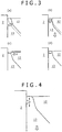
- the mechanism is explained in reference to Fig. 4 .
- a solidified shell 13 having grown in the vicinity of the wall surface of a mold 2 descends by extraction.
- the solidified shell 13 breaks by the frictional force acting at an interface between the grown solidified shell 13 and the mold 2 and the breakage comes to be a surface defect of a slab 11.
- a defect generated by molten metal intrusion caused by the solidification and shrinkage of a solidified shell 13 is estimated to exist.
- the mechanism is explained in reference to Figs. 5(a) to 5(c) .
- Fig. 5(a) an excessively cooled solidified shell 13 solidifies and shrinks and thereby the solidified shell 13 deforms in the direction away from the wall surface of a mold 2.
- molten metal 12 flows into a gap formed between the mold 2 and the solidified shell 13.
- the molten metal 12 having flown into the gap solidifies and comes to be the solidified shell 13. In this way, a surface defect is generated in a solidified shell 13 and comes to be a surface defect of a slab 11.
- a mold 2 is made of copper and is a water-cooled copper mold of a water-cooled type.
- the material of the mold 2 is not limited to copper and a cooling fluid is not limited to water.
- the mold 2 is rectangular in cross-section and the length of the short side is L1 and the length of the long side is L2 as shown in the top view of Fig. 6 .
- the mold 2 includes four corner sections 2a and four face sections 2b.
- each of the face sections 2b is a section interposed between two corner sections 2a and the inner peripheral surfaces and the outer peripheral surfaces of the mold 2 at the face sections 2b are planes.
- the inner peripheral surfaces and the outer peripheral surfaces of the mold 2 at the face sections 2b may somewhat be curved in consideration of thermal deformation.
- the length a of a corner section 2a along a short side and a long side in the horizontal direction is larger than the thickness I of a face section 2b and shorter than a half of the length L1 of the short side of the mold 2 (refer to Fig. 6 ). That is, the length a of a corner section 2a in the horizontal direction, the thickness I of a face section 2b, and the length L1 of the short side of a mold 2 satisfy the relationship represented by the expression I ⁇ a ⁇ L1/2.
- the length of a mold 2 in the vertical direction is 200 to 300 mm.
- the length in the vertical direction of a mold used for continuously casting steel is not less than 600 mm. The reason is that it is unnecessary to increase a cooling range in the vertical direction since titanium or titanium alloy solidifies faster than steel.
- molten metal 12 is likely to be cooled more at a corner section 2a where two sides touch each other than at a face section 2b and hence the growth rate of a solidified shell 13 is larger at the corner section 2a than at the face section 2b. Consequently, by the mechanism explained in reference to Figs. 3(a) to 3(d) and 5(a) to 5(c), a surface defect is likely to be generated more at a corner section 2a. For that reason, in continuous casting of titanium or titanium alloy, it is necessary to reduce a cooling capacity at a corner section 2a and reduce the cooling rate of molten metal 12 touching the corner section 2a. For that reason, as shown in Fig. 6 , a mold 2 has a cooling means 21 for making a thermal flux at four corner sections 2a smaller than a thermal flux at four face sections 2b.
- a thermal flux represents a heat quantity per unit area and unit time.
- a cooling means 21, as shown in Figs. 6 and 7 has first flow channels 22a through which cooling water flows, second flow channels 22b through which cooling water flows, and bypass flow channels 22c connecting the first flow channels 22a to the second flow channels 22b.
- the first flow channels 22a are embedded at four corner sections 2a of a mold 2 and installed extendedly in the horizontal direction respectively.
- the second flow channels 22b are embedded at four face sections 2b of the mold 2 and installed extendedly in the horizontal direction respectively.
- the bypass flow channels 22c are installed extendedly in the horizontal direction.
- Second flow channels 22b may be formed in the range from an upper part to a lower part of a mold 2 as vertically-wide flow channels as shown in Fig. 8(a) that is a sectional view taken on line B-B in Fig. 6 and Fig. 9(a) that is a sectional view taken on line C-C in Fig. 6 . Otherwise, second flow channels 22b may be formed so as to have plural paths at regular intervals in the range from an upper part to a lower part of a mold 2 as shown in Fig. 8(b) that is a sectional view taken on line B-B in Fig. 6 and Fig. 9(b) that is a sectional view taken on line C-C in Fig. 6 .
- the second flow channels 22b may preferably be formed partially at a level equal to the surface of molten metal 12. Then, when a mold 2 is manufactured by fitting an outer frame to the outer periphery of an inner frame on the outer peripheral surface of which grooves are formed, the second flow channels 22b may also be configured so that the grooves of the inner frame may be used as the second flow channels 22b. Further, when a mold 2 is manufactured by casting copper together with a material indissoluble in molten metal of copper, the second flow channels 22b may also be configured so that spaces formed by successively removing the material indissoluble in molten metal of copper may be used as the second flow channels 22b. The same is true for the first flow channels 22a and the bypass flow channels 22c.
- the length of a mold 2 in the vertical direction is shorter than the length of a mold for continuously casting iron or steel.
- the number of the flow channels and the number of pipes each of which connects the outlet of a flow channel to the inlet of another flow channel on the outer peripheral surface of a mold 2 can preferably be reduced further than the case of forming the flow channels in the vertical direction.
- a distance d1 from the inner peripheral surface of a mold 2 to a first flow channel 22a is longer than a distance d2 from the inner peripheral surface of the mold 2 to a second flow channel 22b.
- a thermal flux at the four corner sections 2a of the mold 2 is smaller than a thermal flux at the four face sections 2b of the mold 2.
- a corner of a corner section 2a on the inner peripheral side is set as an original point
- the long side direction is set at the x-axis direction
- the short side direction is set at the y-axis direction
- the distances from the original point to the ends of the corner section 2a in the x-axis and y-axis directions are set at b.
- the thermal conductivity of copper is represented by ⁇ Cu
- a water temperature is represented by Tw
- Ts a surface temperature of a slab 11
- the expression d 1 ⁇ d 2 (a>1) holds.
- a thermal flux at the four corner sections 2a of the mold 2 is smaller than a thermal flux at the four face sections 2b of the mold 2.
- a cooling means 21 has slow-cooling layers 23 embedded at the four corner sections 2a of a mold 2 respectively.
- the slow-cooling layers 23 are embedded on the side closer to the inner peripheral surface of the mold 2 than the first flow channels 22a.
- the slow-cooling layers 23 are air spaces and have smaller thermal conductivity than the mold 2 made of copper. As a result, a thermal flux at the four corner sections 2a of the mold 2 is smaller than a thermal flux at the four face sections 2b of the mold 2.
- the thermal conductivity of copper is represented by ⁇ Cu
- the thermal conductivity of a slow-cooling layer 23 is represented by ⁇ '
- a water temperature is represented by Tw
- the surface temperature of a slab 11 is represented by Ts.
- the distance from the inner peripheral surface of the mold 2 to the slow-cooling layer 23 is represented by d 5
- the thickness of the slow-cooling layer 23 is represented by d 4
- the distance from the slow-cooling layer 23 to a first flow channel 22a is represented by d 3 .
- the expression ⁇ ' ⁇ Cu holds and thus the expression q' ⁇ q holds.
- the thermal flux at the four corner sections 2a where the slow-cooling layers 23 exist is smaller than the thermal flux at the four face sections 2b where no slow-cooling layers 23 exist. Consequently, it is possible to equalize the cooling rate of molten metal 12 at the corner sections 2a and the cooling rate of the molten metal 12 at the face sections 2b.
- the slow-cooling layers 23 are not limited to the air spaces and may also be layers including a metal such as titanium (Ti), tungsten (W), tantalum (Ta), or molybdenum (Mo), each of those having smaller thermal conductivity than copper.
- a metal such as titanium (Ti), tungsten (W), tantalum (Ta), or molybdenum (Mo), each of those having smaller thermal conductivity than copper.
- Figs. 10(a) and 10(b) Successively, two-dimensional heat-transfer and solidification analysis is carried out by using a model shown in Figs. 10(a) and 10(b) .
- Fig.10(a) that is a top view
- the length of the long side of a mold is 1,500 mm
- the length of the short side thereof is 250 mm
- the temperature of a homogeneous heating region 31 is a constant temperature of 2,000°C.
- Fig. 10(b) that is an enlarged view of a substantial part D in Fig. 10(a)
- the length of a corner section in the long side and short side directions is represented by d (mm).
- a heat-transfer coefficient h is set at 1,500 W/m 2 /K and an external temperature is set at 200°C as contact heat-transfer conditions on the outer peripheral surface 32 on the face section side and a heat-transfer coefficient h' is set at ⁇ h and an external temperature is set at 200°C as contact heat-transfer conditions on the outer peripheral surface 33 on the corner section side.
- the expression ⁇ 1 holds.
- a thermal flux at four corner sections 2a of the mold 2 is smaller than a thermal flux at four face sections 2b of the mold 2.
- molten metal 12 touching four corner sections 2a of a mold 2 is cooled by cooling water flowing through first flow channels 22a embedded at the corner sections 2a respectively. Furthermore, molten metal 12 touching four face sections 2b of the mold 2 is cooled by cooling water flowing through second flow channels 22b embedded at the face sections 2b respectively.
- a thermal flux at the four corner sections 2a of the mold 2 is smaller than a thermal flux at the four face sections 2b of the mold 2. As a result, it is possible to equalize the cooling rate of molten metal 12 at the corner sections 2a and the cooling rate of the molten metal 12 at the face sections 2b.
- first flow channels 22a to second flow channels 22b, those being installed extendedly in the horizontal direction, through bypass flow channels 22c, it is possible to make cooling water flow from the first flow channels 22a to the second flow channels 22b. Consequently, it is possible to: reduce the number of the outlets and inlets of the flow channels; and allow the cooling water to flow easily.
- a thermal flux at four corner sections 2a of a mold 2 is smaller than a thermal flux at four face sections 2b of the mold 2 by slow-cooling layers 23 embedded at the four corner sections 2a of the mold 2 respectively.
- a continuous casting device 201 according to the second embodiment of the present invention is explained hereunder.
- a constituent component identical to an aforementioned constituent component is represented by an identical reference numeral and the explanations are omitted.
- the different point of the continuous casting device 201 according to the present embodiment from a continuous casting device 1 according to the first embodiment is that, as shown in Fig. 13 that is a top view, a mold 202 has a cooling means 221 that makes a thermal flux at four corner sections 2a smaller than a thermal flux at four face sections 2b.
- the cooling means 221 has flow channels 222 through which cooling water flows.
- the flow channels 222 are embedded at the four face sections 2b of the mold 202 and installed extendedly in the horizontal direction respectively.
- Inlet passages 223 to introduce cooling water into the flow channels 222 and outlet passages 224 to exhaust the cooling water from the flow channels 222 are connected to the flow channels 222 respectively.
- the cooling means 221 has no flow channels at the four corner sections 2a.
- a thermal flux at the four corner sections 2a of the mold 202 is smaller than a thermal flux at the four face sections 2b of the mold 202.
- the cooling means 221 has slow-cooling layers 23 embedded at the four corner sections 2a respectively in the same manner as the first embodiment.
- molten metal 12 touching four face sections 2b of the mold 202 is cooled by cooling water flowing through flow channels 222 embedded at the face sections 2b respectively.
- a thermal flux at the four corner sections 2a of the mold 202 is smaller than a thermal flux at the four face sections 2b of the mold 202.
- a continuous casting device 301 according to the third embodiment of the present invention is explained hereunder.
- a constituent component identical to an aforementioned constituent component is represented by an identical reference numeral and the explanations are omitted.
- the different point of the continuous casting device 301 according to the present embodiment from a continuous casting device 1 according to the first embodiment is that, as shown in Fig. 14 that is a top view, a mold 302 has a cooling means 321 that makes a thermal flux at four corner sections 2a smaller than a thermal flux at four face sections 2b.
- the cooling means 321 has first flow channels 322a through which cooling water flows and second flow channels 322b through which the cooling water flows.
- the first flow channels 322a are embedded at the four corner sections 2a of the mold 302 and installed extendedly in the horizontal direction respectively.
- the second flow channels 322b are embedded at the four face sections 2b of the mold 302 and installed extendedly in the horizontal direction respectively.
- Inlet passages 323 to introduce the cooling water into the flow channels 322a and 322b are connected to the flow channels 322a and 322b.
- outlet passages 324 to exhaust the cooling water from the flow channels 322a and 322b are connected to the flow channels 322a and 322b.
- the first flow channels 322a do not communicate with the second flow channels 322b.
- a distance d 1 from the inner peripheral surface of the mold 302 to a first flow channel 322a is longer than a distance d 2 from the inner peripheral surface of the mold 302 to a second flow channel 322b.
- a thermal flux at the four corner sections 2a of the mold 302 is smaller than a thermal flux at the four face sections 2b of the mold 302.
- a flow rate of cooling water flowing through the first flow channels 322a is set to be lower than a flow rate of the cooling water flowing through the second flow channels 322b.
- a thermal flux at the four corner sections 2a so as to be smaller than a thermal flux at the four face sections 2b.
- a flow quantity Q of cooling water is constant in the first flow channels 322a and the second flow channels 322b, it is possible to control the flow rate u of the cooling water by adjusting the flow channel diameter e at the corner sections 2a and the face sections 2b.
- the flow channel diameter e is identical at the first flow channels 322a and the second flow channels 322b, it is possible to control the flow rate u of the cooling water by adjusting the flow quantity Q at the corner sections 2a and the face sections 2b.
- a temperature of the cooling water flowing through the first flow channels 322a may be set to be higher than a temperature of the cooling water flowing through the second flow channels 322b.
- the cooling means 321 has slow-cooling layers 23 embedded at the four corner sections 2a respectively in the same manner as the first embodiment.
- a configuration of heating the surface of molten metal 12 by a plasma arc generated from a plasma torch 7 is appropriate but the present invention is not limited to the configuration.
- a configuration of heating the surface of molten metal 12 by an electron beam, a non-consumable electrode type arc, or high-frequency induction heating may be adopted.
- first flow channels 22a, second flow channels 22b, and bypass flow channels 22c according to the first embodiment, flow channels 222 according to the second embodiment, and first flow channels 322a and second flow channels 322b according to the third embodiment are all installed extendedly in the horizontal direction, they may be installed extendedly in the vertical direction.
Landscapes
- Engineering & Computer Science (AREA)
- Mechanical Engineering (AREA)
- Continuous Casting (AREA)
Applications Claiming Priority (2)
| Application Number | Priority Date | Filing Date | Title |
|---|---|---|---|
| JP2012083683A JP5896811B2 (ja) | 2012-04-02 | 2012-04-02 | チタンまたはチタン合金からなる鋳塊の連続鋳造用の鋳型およびこれを備えた連続鋳造装置 |
| PCT/JP2013/060116 WO2013151061A1 (ja) | 2012-04-02 | 2013-04-02 | チタンまたはチタン合金からなる鋳塊の連続鋳造用の鋳型およびこれを備えた連続鋳造装置 |
Publications (3)
| Publication Number | Publication Date |
|---|---|
| EP2835191A1 EP2835191A1 (en) | 2015-02-11 |
| EP2835191A4 EP2835191A4 (en) | 2016-04-06 |
| EP2835191B1 true EP2835191B1 (en) | 2019-06-12 |
Family
ID=49300542
Family Applications (1)
| Application Number | Title | Priority Date | Filing Date |
|---|---|---|---|
| EP13772966.1A Active EP2835191B1 (en) | 2012-04-02 | 2013-04-02 | Mold for continuous casting of titanium or titanium alloy ingot, and continuous casting device provided with same |
Country Status (7)
| Country | Link |
|---|---|
| US (1) | US9156081B2 (ru) |
| EP (1) | EP2835191B1 (ru) |
| JP (1) | JP5896811B2 (ru) |
| KR (1) | KR20140129338A (ru) |
| CN (1) | CN104185519B (ru) |
| EA (1) | EA201491829A1 (ru) |
| WO (1) | WO2013151061A1 (ru) |
Families Citing this family (3)
| Publication number | Priority date | Publication date | Assignee | Title |
|---|---|---|---|---|
| JP6279963B2 (ja) * | 2014-04-15 | 2018-02-14 | 株式会社神戸製鋼所 | チタンまたはチタン合金からなるスラブの連続鋳造装置 |
| WO2018074406A1 (ja) | 2016-10-19 | 2018-04-26 | Jfeスチール株式会社 | 連続鋳造用鋳型及び鋼の連続鋳造方法 |
| JP7471946B2 (ja) | 2020-07-31 | 2024-04-22 | 東邦チタニウム株式会社 | チタン系インゴットの製造方法 |
Family Cites Families (16)
| Publication number | Priority date | Publication date | Assignee | Title |
|---|---|---|---|---|
| US3336973A (en) * | 1964-10-20 | 1967-08-22 | Babcock & Wilcox Co | Continuous casting mold |
| DE2005059A1 (de) * | 1970-02-16 | 1971-08-19 | Ural Sawod Tjyselogo Mash Jeni | Kokille fur Metallstranggießanlage |
| JPH0399752A (ja) * | 1989-09-11 | 1991-04-24 | Kobe Steel Ltd | 高融点且つ活性な金属の連続鋳造用鋳型 |
| US5379828A (en) * | 1990-12-10 | 1995-01-10 | Inland Steel Company | Apparatus and method for continuous casting of molten steel |
| CH685432A5 (de) * | 1992-06-11 | 1995-07-14 | Concast Standard Ag | Kokille zum Stranggiessen von Metall, insbesondere von Stahl in Knüppel- und Vorblockquerschnitte. |
| JPH07116783A (ja) | 1993-10-21 | 1995-05-09 | Sumitomo Metal Ind Ltd | 連続鋳造用鋳型およびこれを用いる鋳片の冷却方法 |
| JPH07118773A (ja) | 1993-10-21 | 1995-05-09 | Nippon Steel Corp | チタンまたはチタン合金圧延材の製造方法 |
| DE69518360T2 (de) * | 1994-06-06 | 2000-12-28 | Danieli Off Mecc | Stranggiesskokille mit verbessertem Wärmeaustausch sowie Verfahren zur Erhöhung des Wärmeaustauschs einer Stranggiesskokille |
| EP0686445B1 (en) * | 1994-06-06 | 2000-08-16 | DANIELI & C. OFFICINE MECCANICHE S.p.A. | Method to control the deformations of the sidewalls of a crystalliser, and continuous-casting crystalliser |
| ATE195450T1 (de) * | 1994-06-06 | 2000-09-15 | Danieli Off Mecc | Stranggiesskokille mit verbessertem wärmeaustausch sowie verfahren zur erhöhung des wärmeaustauschs einer stranggiesskokille |
| JP3389449B2 (ja) | 1997-04-16 | 2003-03-24 | 新日本製鐵株式会社 | 角型ビレットの連続鋳造方法 |
| IT1310518B1 (it) * | 1999-01-13 | 2002-02-18 | Danieli Off Mecc | Dispositivo per colata continua ad alta velocita' e relativoprocedimento |
| ES2242119T3 (es) * | 2003-04-16 | 2005-11-01 | Concast Ag | Lingotera tubular para la colada continua. |
| CN2652559Y (zh) * | 2003-09-05 | 2004-11-03 | 周嘉平 | 一种炼钢连铸用均匀冷却高效结晶器 |
| SG173514A1 (en) * | 2009-02-09 | 2011-09-29 | Toho Titanium Co Ltd | Titanium slab for hot rolling produced by electron-beam melting furnace, process for production thereof, and process for rolling titanium slam for hot rolling |
| CN102151808B (zh) * | 2011-04-22 | 2013-11-20 | 马鞍山马钢表面工程技术有限公司 | 大异型坯连铸结晶器冷却水通道 |
-
2012
- 2012-04-02 JP JP2012083683A patent/JP5896811B2/ja not_active Expired - Fee Related
-
2013
- 2013-04-02 EP EP13772966.1A patent/EP2835191B1/en active Active
- 2013-04-02 EA EA201491829A patent/EA201491829A1/ru unknown
- 2013-04-02 KR KR1020147027392A patent/KR20140129338A/ko active Search and Examination
- 2013-04-02 WO PCT/JP2013/060116 patent/WO2013151061A1/ja active Application Filing
- 2013-04-02 CN CN201380016140.1A patent/CN104185519B/zh not_active Expired - Fee Related
- 2013-04-02 US US14/376,301 patent/US9156081B2/en not_active Expired - Fee Related
Non-Patent Citations (1)
| Title |
|---|
| None * |
Also Published As
| Publication number | Publication date |
|---|---|
| CN104185519B (zh) | 2016-02-10 |
| JP5896811B2 (ja) | 2016-03-30 |
| US9156081B2 (en) | 2015-10-13 |
| EP2835191A1 (en) | 2015-02-11 |
| JP2013212518A (ja) | 2013-10-17 |
| CN104185519A (zh) | 2014-12-03 |
| KR20140129338A (ko) | 2014-11-06 |
| WO2013151061A1 (ja) | 2013-10-10 |
| EA201491829A1 (ru) | 2015-01-30 |
| US20150047801A1 (en) | 2015-02-19 |
| EP2835191A4 (en) | 2016-04-06 |
Similar Documents
| Publication | Publication Date | Title |
|---|---|---|
| CN101602102B (zh) | 外加小温度梯度消除铸件缩孔缩松的凝固过程控制方法 | |
| JP6743034B2 (ja) | 超音波結晶粒微細化 | |
| TWI290071B (en) | Steel continuous casting plant for billet and cogged ingot formats | |
| JP5918572B2 (ja) | チタン鋳塊およびチタン合金鋳塊の連続鋳造装置および連続鋳造方法 | |
| EP2835191B1 (en) | Mold for continuous casting of titanium or titanium alloy ingot, and continuous casting device provided with same | |
| JP5788691B2 (ja) | 金属溶製用溶解炉およびこれを用いた金属の溶製方法 | |
| EP3556487B1 (en) | Casting method for active metal | |
| CN104109760A (zh) | 钢锭的中频感应炉电渣炉双联冶炼系统、冶炼方法及钢锭 | |
| JP2010247202A (ja) | 金属インゴットの溶製装置および同装置を用いた金属インゴットの溶製方法 | |
| EP3192593A1 (en) | Method for continuously casting slab containing titanium or titanium alloy | |
| JPH06263B2 (ja) | 連続鋳造法 | |
| JP5730738B2 (ja) | チタンまたはチタン合金からなるスラブの連続鋳造方法および連続鋳造装置 | |
| JP5774438B2 (ja) | チタンまたはチタン合金からなるスラブの連続鋳造方法および連続鋳造装置 | |
| US6250365B1 (en) | Die casting process | |
| JP5627015B2 (ja) | チタンまたはチタン合金からなるスラブの連続鋳造方法および連続鋳造装置 | |
| Thomas | Continuous casting (metallurgy) | |
| WO2018110370A1 (ja) | 活性金属の鋳造方法 | |
| JP4672203B2 (ja) | 金ボンディングワイヤ用インゴットの製造方法 | |
| EP3225329A1 (en) | Method for continuously casting slab containing titanium or titanium alloy | |
| JPH08132184A (ja) | 丸ビレット鋳片の連続鋳造用鋳型及びその鋳型を用いた連続鋳造方法 | |
| JP5701720B2 (ja) | チタンまたはチタン合金からなる鋳塊の連続鋳造用の鋳型およびこれを備えた連続鋳造装置 | |
| JPH04162954A (ja) | 金属の連続的溶解および鋳造装置 | |
| JPH04316980A (ja) | 凝固したスカルの取出しが容易なコールドウォールルツボ炉とその製造方法 | |
| JPH01166868A (ja) | 連続鋳造装置 | |
| JP2000210757A (ja) | 非鉄金属鋳塊の縦型半連続鋳造用鋳型 |
Legal Events
| Date | Code | Title | Description |
|---|---|---|---|
| PUAI | Public reference made under article 153(3) epc to a published international application that has entered the european phase |
Free format text: ORIGINAL CODE: 0009012 |
|
| 17P | Request for examination filed |
Effective date: 20140806 |
|
| AK | Designated contracting states |
Kind code of ref document: A1 Designated state(s): AL AT BE BG CH CY CZ DE DK EE ES FI FR GB GR HR HU IE IS IT LI LT LU LV MC MK MT NL NO PL PT RO RS SE SI SK SM TR |
|
| AX | Request for extension of the european patent |
Extension state: BA ME |
|
| DAX | Request for extension of the european patent (deleted) | ||
| RA4 | Supplementary search report drawn up and despatched (corrected) |
Effective date: 20160304 |
|
| RIC1 | Information provided on ipc code assigned before grant |
Ipc: B22D 11/055 20060101AFI20160229BHEP |
|
| STAA | Information on the status of an ep patent application or granted ep patent |
Free format text: STATUS: EXAMINATION IS IN PROGRESS |
|
| RIC1 | Information provided on ipc code assigned before grant |
Ipc: B22D 21/00 20060101ALI20170727BHEP Ipc: B22D 11/055 20060101AFI20170727BHEP |
|
| 17Q | First examination report despatched |
Effective date: 20170824 |
|
| GRAP | Despatch of communication of intention to grant a patent |
Free format text: ORIGINAL CODE: EPIDOSNIGR1 |
|
| STAA | Information on the status of an ep patent application or granted ep patent |
Free format text: STATUS: GRANT OF PATENT IS INTENDED |
|
| RIC1 | Information provided on ipc code assigned before grant |
Ipc: B22D 11/055 20060101AFI20180917BHEP Ipc: B22D 21/00 20060101ALI20180917BHEP Ipc: B22D 11/041 20060101ALI20180917BHEP |
|
| INTG | Intention to grant announced |
Effective date: 20181019 |
|
| GRAS | Grant fee paid |
Free format text: ORIGINAL CODE: EPIDOSNIGR3 |
|
| GRAA | (expected) grant |
Free format text: ORIGINAL CODE: 0009210 |
|
| STAA | Information on the status of an ep patent application or granted ep patent |
Free format text: STATUS: THE PATENT HAS BEEN GRANTED |
|
| AK | Designated contracting states |
Kind code of ref document: B1 Designated state(s): AL AT BE BG CH CY CZ DE DK EE ES FI FR GB GR HR HU IE IS IT LI LT LU LV MC MK MT NL NO PL PT RO RS SE SI SK SM TR |
|
| REG | Reference to a national code |
Ref country code: GB Ref legal event code: FG4D |
|
| REG | Reference to a national code |
Ref country code: CH Ref legal event code: EP |
|
| REG | Reference to a national code |
Ref country code: AT Ref legal event code: REF Ref document number: 1141933 Country of ref document: AT Kind code of ref document: T Effective date: 20190615 |
|
| REG | Reference to a national code |
Ref country code: DE Ref legal event code: R096 Ref document number: 602013056550 Country of ref document: DE |
|
| REG | Reference to a national code |
Ref country code: IE Ref legal event code: FG4D |
|
| REG | Reference to a national code |
Ref country code: NL Ref legal event code: MP Effective date: 20190612 |
|
| REG | Reference to a national code |
Ref country code: LT Ref legal event code: MG4D |
|
| PG25 | Lapsed in a contracting state [announced via postgrant information from national office to epo] |
Ref country code: FI Free format text: LAPSE BECAUSE OF FAILURE TO SUBMIT A TRANSLATION OF THE DESCRIPTION OR TO PAY THE FEE WITHIN THE PRESCRIBED TIME-LIMIT Effective date: 20190612 Ref country code: LT Free format text: LAPSE BECAUSE OF FAILURE TO SUBMIT A TRANSLATION OF THE DESCRIPTION OR TO PAY THE FEE WITHIN THE PRESCRIBED TIME-LIMIT Effective date: 20190612 Ref country code: SE Free format text: LAPSE BECAUSE OF FAILURE TO SUBMIT A TRANSLATION OF THE DESCRIPTION OR TO PAY THE FEE WITHIN THE PRESCRIBED TIME-LIMIT Effective date: 20190612 Ref country code: NO Free format text: LAPSE BECAUSE OF FAILURE TO SUBMIT A TRANSLATION OF THE DESCRIPTION OR TO PAY THE FEE WITHIN THE PRESCRIBED TIME-LIMIT Effective date: 20190912 Ref country code: HR Free format text: LAPSE BECAUSE OF FAILURE TO SUBMIT A TRANSLATION OF THE DESCRIPTION OR TO PAY THE FEE WITHIN THE PRESCRIBED TIME-LIMIT Effective date: 20190612 Ref country code: AL Free format text: LAPSE BECAUSE OF FAILURE TO SUBMIT A TRANSLATION OF THE DESCRIPTION OR TO PAY THE FEE WITHIN THE PRESCRIBED TIME-LIMIT Effective date: 20190612 |
|
| PG25 | Lapsed in a contracting state [announced via postgrant information from national office to epo] |
Ref country code: GR Free format text: LAPSE BECAUSE OF FAILURE TO SUBMIT A TRANSLATION OF THE DESCRIPTION OR TO PAY THE FEE WITHIN THE PRESCRIBED TIME-LIMIT Effective date: 20190913 Ref country code: BG Free format text: LAPSE BECAUSE OF FAILURE TO SUBMIT A TRANSLATION OF THE DESCRIPTION OR TO PAY THE FEE WITHIN THE PRESCRIBED TIME-LIMIT Effective date: 20190912 Ref country code: RS Free format text: LAPSE BECAUSE OF FAILURE TO SUBMIT A TRANSLATION OF THE DESCRIPTION OR TO PAY THE FEE WITHIN THE PRESCRIBED TIME-LIMIT Effective date: 20190612 Ref country code: LV Free format text: LAPSE BECAUSE OF FAILURE TO SUBMIT A TRANSLATION OF THE DESCRIPTION OR TO PAY THE FEE WITHIN THE PRESCRIBED TIME-LIMIT Effective date: 20190612 |
|
| REG | Reference to a national code |
Ref country code: AT Ref legal event code: MK05 Ref document number: 1141933 Country of ref document: AT Kind code of ref document: T Effective date: 20190612 |
|
| PG25 | Lapsed in a contracting state [announced via postgrant information from national office to epo] |
Ref country code: EE Free format text: LAPSE BECAUSE OF FAILURE TO SUBMIT A TRANSLATION OF THE DESCRIPTION OR TO PAY THE FEE WITHIN THE PRESCRIBED TIME-LIMIT Effective date: 20190612 Ref country code: SK Free format text: LAPSE BECAUSE OF FAILURE TO SUBMIT A TRANSLATION OF THE DESCRIPTION OR TO PAY THE FEE WITHIN THE PRESCRIBED TIME-LIMIT Effective date: 20190612 Ref country code: PT Free format text: LAPSE BECAUSE OF FAILURE TO SUBMIT A TRANSLATION OF THE DESCRIPTION OR TO PAY THE FEE WITHIN THE PRESCRIBED TIME-LIMIT Effective date: 20191014 Ref country code: AT Free format text: LAPSE BECAUSE OF FAILURE TO SUBMIT A TRANSLATION OF THE DESCRIPTION OR TO PAY THE FEE WITHIN THE PRESCRIBED TIME-LIMIT Effective date: 20190612 Ref country code: NL Free format text: LAPSE BECAUSE OF FAILURE TO SUBMIT A TRANSLATION OF THE DESCRIPTION OR TO PAY THE FEE WITHIN THE PRESCRIBED TIME-LIMIT Effective date: 20190612 Ref country code: RO Free format text: LAPSE BECAUSE OF FAILURE TO SUBMIT A TRANSLATION OF THE DESCRIPTION OR TO PAY THE FEE WITHIN THE PRESCRIBED TIME-LIMIT Effective date: 20190612 Ref country code: CZ Free format text: LAPSE BECAUSE OF FAILURE TO SUBMIT A TRANSLATION OF THE DESCRIPTION OR TO PAY THE FEE WITHIN THE PRESCRIBED TIME-LIMIT Effective date: 20190612 |
|
| PG25 | Lapsed in a contracting state [announced via postgrant information from national office to epo] |
Ref country code: SM Free format text: LAPSE BECAUSE OF FAILURE TO SUBMIT A TRANSLATION OF THE DESCRIPTION OR TO PAY THE FEE WITHIN THE PRESCRIBED TIME-LIMIT Effective date: 20190612 Ref country code: ES Free format text: LAPSE BECAUSE OF FAILURE TO SUBMIT A TRANSLATION OF THE DESCRIPTION OR TO PAY THE FEE WITHIN THE PRESCRIBED TIME-LIMIT Effective date: 20190612 Ref country code: IT Free format text: LAPSE BECAUSE OF FAILURE TO SUBMIT A TRANSLATION OF THE DESCRIPTION OR TO PAY THE FEE WITHIN THE PRESCRIBED TIME-LIMIT Effective date: 20190612 Ref country code: IS Free format text: LAPSE BECAUSE OF FAILURE TO SUBMIT A TRANSLATION OF THE DESCRIPTION OR TO PAY THE FEE WITHIN THE PRESCRIBED TIME-LIMIT Effective date: 20191012 |
|
| REG | Reference to a national code |
Ref country code: DE Ref legal event code: R097 Ref document number: 602013056550 Country of ref document: DE |
|
| PG25 | Lapsed in a contracting state [announced via postgrant information from national office to epo] |
Ref country code: TR Free format text: LAPSE BECAUSE OF FAILURE TO SUBMIT A TRANSLATION OF THE DESCRIPTION OR TO PAY THE FEE WITHIN THE PRESCRIBED TIME-LIMIT Effective date: 20190612 |
|
| PLBE | No opposition filed within time limit |
Free format text: ORIGINAL CODE: 0009261 |
|
| STAA | Information on the status of an ep patent application or granted ep patent |
Free format text: STATUS: NO OPPOSITION FILED WITHIN TIME LIMIT |
|
| PG25 | Lapsed in a contracting state [announced via postgrant information from national office to epo] |
Ref country code: PL Free format text: LAPSE BECAUSE OF FAILURE TO SUBMIT A TRANSLATION OF THE DESCRIPTION OR TO PAY THE FEE WITHIN THE PRESCRIBED TIME-LIMIT Effective date: 20190612 Ref country code: DK Free format text: LAPSE BECAUSE OF FAILURE TO SUBMIT A TRANSLATION OF THE DESCRIPTION OR TO PAY THE FEE WITHIN THE PRESCRIBED TIME-LIMIT Effective date: 20190612 |
|
| 26N | No opposition filed |
Effective date: 20200313 |
|
| PG25 | Lapsed in a contracting state [announced via postgrant information from national office to epo] |
Ref country code: IS Free format text: LAPSE BECAUSE OF FAILURE TO SUBMIT A TRANSLATION OF THE DESCRIPTION OR TO PAY THE FEE WITHIN THE PRESCRIBED TIME-LIMIT Effective date: 20200224 Ref country code: SI Free format text: LAPSE BECAUSE OF FAILURE TO SUBMIT A TRANSLATION OF THE DESCRIPTION OR TO PAY THE FEE WITHIN THE PRESCRIBED TIME-LIMIT Effective date: 20190612 |
|
| PG2D | Information on lapse in contracting state deleted |
Ref country code: IS |
|
| PG25 | Lapsed in a contracting state [announced via postgrant information from national office to epo] |
Ref country code: MC Free format text: LAPSE BECAUSE OF FAILURE TO SUBMIT A TRANSLATION OF THE DESCRIPTION OR TO PAY THE FEE WITHIN THE PRESCRIBED TIME-LIMIT Effective date: 20190612 |
|
| REG | Reference to a national code |
Ref country code: CH Ref legal event code: PL |
|
| PG25 | Lapsed in a contracting state [announced via postgrant information from national office to epo] |
Ref country code: LI Free format text: LAPSE BECAUSE OF NON-PAYMENT OF DUE FEES Effective date: 20200430 Ref country code: CH Free format text: LAPSE BECAUSE OF NON-PAYMENT OF DUE FEES Effective date: 20200430 Ref country code: FR Free format text: LAPSE BECAUSE OF NON-PAYMENT OF DUE FEES Effective date: 20200430 Ref country code: LU Free format text: LAPSE BECAUSE OF NON-PAYMENT OF DUE FEES Effective date: 20200402 |
|
| REG | Reference to a national code |
Ref country code: BE Ref legal event code: MM Effective date: 20200430 |
|
| PG25 | Lapsed in a contracting state [announced via postgrant information from national office to epo] |
Ref country code: BE Free format text: LAPSE BECAUSE OF NON-PAYMENT OF DUE FEES Effective date: 20200430 |
|
| GBPC | Gb: european patent ceased through non-payment of renewal fee |
Effective date: 20200402 |
|
| PG25 | Lapsed in a contracting state [announced via postgrant information from national office to epo] |
Ref country code: IE Free format text: LAPSE BECAUSE OF NON-PAYMENT OF DUE FEES Effective date: 20200402 Ref country code: GB Free format text: LAPSE BECAUSE OF NON-PAYMENT OF DUE FEES Effective date: 20200402 |
|
| PGFP | Annual fee paid to national office [announced via postgrant information from national office to epo] |
Ref country code: DE Payment date: 20210316 Year of fee payment: 9 |
|
| PG25 | Lapsed in a contracting state [announced via postgrant information from national office to epo] |
Ref country code: MT Free format text: LAPSE BECAUSE OF FAILURE TO SUBMIT A TRANSLATION OF THE DESCRIPTION OR TO PAY THE FEE WITHIN THE PRESCRIBED TIME-LIMIT Effective date: 20190612 Ref country code: CY Free format text: LAPSE BECAUSE OF FAILURE TO SUBMIT A TRANSLATION OF THE DESCRIPTION OR TO PAY THE FEE WITHIN THE PRESCRIBED TIME-LIMIT Effective date: 20190612 |
|
| PG25 | Lapsed in a contracting state [announced via postgrant information from national office to epo] |
Ref country code: MK Free format text: LAPSE BECAUSE OF FAILURE TO SUBMIT A TRANSLATION OF THE DESCRIPTION OR TO PAY THE FEE WITHIN THE PRESCRIBED TIME-LIMIT Effective date: 20190612 |
|
| REG | Reference to a national code |
Ref country code: DE Ref legal event code: R119 Ref document number: 602013056550 Country of ref document: DE |
|
| PG25 | Lapsed in a contracting state [announced via postgrant information from national office to epo] |
Ref country code: DE Free format text: LAPSE BECAUSE OF NON-PAYMENT OF DUE FEES Effective date: 20221103 |